electro-hydraulic power steering (ehps) systems in
TRANSCRIPT

www.infineon.com
Electro-Hydraulic Power Steering (EHPS) systems in commercial, construction and agricultural vehicles (CAV) With technology from Infineon
System benefits › Energy/fuel savings and CO2 reduction due to power on demand
› Reduction of accident and insurance costs due to keep lanes assist
› Support truck AD level > 3 due to fail operational steering
› Infineon EHPS know-how due to system offer: MCU, sensor and power

– 2 of 14 –
Contents
1. Trends in CAV market 3
2. The road to autonomy 4
2.1 From constant power to power-on-demand 6
2.2 The system level view 7
3. Infineon – a ‘one stop shop’ for EHPS compnents 8
3.1 Microcontrollers 8
3.2 Safety power supplies 9
3.3 MOSFET gate drivers 10
3.4 Automotive-grade MOSFETs 11
3.5 Connectivity 11
3.6 Sensors 11
4. Conclusion 12
5. References 13
Abstract
While electric cars dominate the headlines, there is a quiet revolution happening in the commercial, construction and agricultural vehicle (CAV) markets. Because of the disproportionate contribution these vehicles make to overall emissions, significant development work is in progress to ‘electrify’ them, which will also deliver benefits in safety, operating costs and energy savings. With the ultimate goal of fully autonomous vehicles in
sight, electrically controlled steering is a critical addition, but there are also advantages to electrifying traditional hydraulic systems to support semi-autonomous driving functions such as lane departure correction. This white paper looks at the e-CAV landscape and some of the components from Infineon that facilitate designs for drives, controllers and sensors in Electro-Hydraulic Power Steering (EHPS).

– 3 of 14 –
1. Trends in CAV market
Increased fuel efficiency, lower emissions, safety and connectivity are major trends in commercial, construction and agricultural vehicles (CAV). The CAV acronym also helpfully stands for ‘Connected Autonomous Vehicles’
and the two converge; the future will be vehicles that are networked and sense their environment with the prospect of complete autonomy in a safe manner, while saving fuel and operating costs (Figure 1).
When more vehicle autonomy is proposed, safety must be the first consideration, so design and component reliability is paramount. Even in the best designs, failures can, and do happen, so system redundancy is necessary with the associated monitoring, to be assured all is working correctly. Autonomy does offer the prospect of additional safety features though, with electronically activated emergency braking for example or alerting the driver if the vehicle drifts out of its lane. It has been estimated that in Germany about 40 percent of accidents attributed to trucks unintentionally leaving a lane could be prevented by the addition of an automated system [1]. Even ‘platooning’ – the aggregation of trucks into convoys – can be seen as a safety benefit, with the platoon acting as one unit rather than multiple independent vehicles with their inherent unpredictability. Cruise control has been around for many years, but full autonomy and even driverless vehicles are the ultimate goal. Combined with cameras and on-board processors, systems today can give comprehensive Lane Departure Warning (LDW) and correction and are capable of meeting the regulatory safety standards for the highest level of automated driving for the future. In fact, in the EU, LDW has been a mandatory feature in new trucks over 3.5 tonnes and buses over 5 tonnes since the end of 2015, to reduce accidents and consequent insurance costs.
Fuel efficiency is also a major driver towards the full electrification of vehicles, a trend that is inevitable in the face of emissions regulations getting tighter. However, there are also advantages to be gained by incorporating electrically powered auxiliary equipment into hybrid and even conventional gasoline-powered vehicles, over conventional belt-driven systems.
Electrification leading to full autonomy is enabled by connectivity within and between vehicles. This will be implemented using CAN bus or Ethernet within the vehicle, and through GPS, 3/4/5G and versions of Wi-Fi for vehicle-to-vehicle and vehicle-to-infrastructure communications. However, data security becomes critical along with guaranteed continuity of infrastructure services and their energy supplies.
The trends outlined all interact and provide a set of multidisciplinary challenges for CAV OEMs. Functional safety is central, requiring fail-safe designs and comprehensive diagnostics. Data security must be ensured with the increasing complexity of electronics and communications, and power levels reaching hundreds of kilowatts must be handled and distributed efficiently within the vehicle.
Figure 1 Trends in commercial, construction and agricultural vehicles
Fuel efficiency
Safety & ADAS Connectivity

What does the human in the driver’s seat have to do?
What do these features do?
Example features
– 4 of 14 –
2. The road to autonomy
In this white paper, we’ll now consider the progress towards autonomy in trucks, which is the main focus of technology development, although the same will eventually apply to construction and agricultural vehicles with different challenges and benefits.
The Society of Automotive Engineers (SAE) has defined levels of driving automation in their document J3016 [2] (Figure 2). At level 0, the driver must be fully in control and
be ready to intervene at all times but some Automated Driving Assistance Systems (ADAS) features are available, such as Automatic Braking Systems (ABS), blind spot warning and LDW. As the levels climb, more features become available such as lane centering and automatic steering. Above level 3 the driver may give complete control to the electronics, with level 4 being typical for a driverless taxi. At level 5 no driver intervention is required anywhere, under any conditions.
Figure 2 Levels of driving automation – source: SAE J3016
SAE J3016™ LEVELS OF DRIVING AUTOMATION
› Automatic emergency braking
› Blind spot warning
› Lane departure warning
› Traffic jam chauffeur
› Lane cen-tering
OR › Adaptive cruise control
› Local driv-erless taxi
› Pedals/ steering wheel may or may not be installed
› Lane cen-tering
AND › Adaptive cruise control at the same time
› Same as level 4, but feature can drive every-where in all conditions
These features are limited to providing warnings and momentary assistance
These features can drive the vehicle under limited conditions and will not operate unless all required conditions are met
These features provide steering OR brake/ acceleration support to the driver
These features provide steering AND brake/acceleration support to the driver
This feature can drive the vehicle under all conditions
You are driving whenever these driver support features are engaged – even if your feet are off the pedals and you are not steering
You are not driving when these automated driving features are engaged – even if you are seated in “the driver’s seat”
you must drive
You must constantly supervise these support features; you must steer, brake or accelerate as needed to maintain safety
When the feature requests,
These automated driving features will not require you to take over driving
SAE Level 0
SAE Level 1
SAE Level 2
SAE Level 3
SAE Level 4
SAE Level 5
These are driver support features These are automated driving features
For a more complete description, please download a free copy of SAE J3016: https://www.sae.org/standards/content/J3016_201806/
– 5 of 14 –
The classification of hazards caused by failure of elements of an automotive control system are defined in ISO 26262 [3], an adaptation of IEC 61508 [4], which defines Safety Integrity Levels (SIL). For the automotive industry, Automotive Safety Integrity Levels (ASIL) apply, ranging from ASIL-A to the most severe ASIL-D. The hazard level allocated depends on the automation level involved. For example, error in failure of the sensor for steering wheel angle in SAE level 2, providing tactile feedback to the driver, is a low-level hazard, perhaps
ASIL-A. In automation level 4 or 5 where steering is entirely automatic, error in the sensor could be catastrophic and justifies ASIL-D. ASIL level is determined by a hazard analysis and risk assessment with the severity of the effect moderated by the likelihood of the effect happening and the degree of control that a driver may have in acting to prevent injury. These are termed Severity (S0 – S3), Exposure (E0 – E4) and Controllability (C0 – C3) classifications. ASIL-D would therefore, for example, be a combination of S3, E4 and C3.
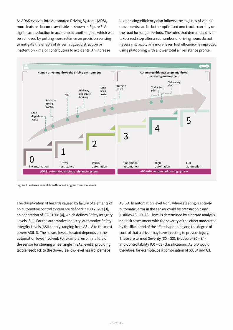
As ADAS evolves into Automated Driving Systems (ADS), more features become available as shown in Figure 5. A significant reduction in accidents is another goal, which will be achieved by putting more reliance on precision sensing to mitigate the effects of driver fatigue, distraction or inattention – major contributors to accidents. An increase
in operating efficiency also follows; the logistics of vehicle movements can be better optimised and trucks can stay on the road for longer periods. The rules that demand a driver take a rest stop after a set number of driving hours do not necessarily apply any more. Even fuel efficiency is improved using platooning with a lower total air resistance profile.
Figure 3 Features available with increasing automation levels
01
23
45
No automationDriverassistance
Partialautomation
Conditionalautomation
Highautomation
Fullautomation
Lanedepartureassist
Adaptivecruisecontrol
ABS
Highwaydeparturebraking
Lanekeepassist
Turning assist
Tra�ic jampilot
Platooningpilot
Human driver monitors the driving environment Automated driving system monitorsthe driving environment
ADAS: automated driving assistance system ADS (AD): automated driving system

– 6 of 14 –
2.1 From constant power to power-on-demand
Vehicles have basically three controls: brakes, accelerator and steering. ABS and cruise controls are mature technologies and can be linked into on-board processors to contribute to autonomous driving. Automated electrical steering however has only recently come into the picture and so far, has only been an add-on to traditional hydraulic systems for power assistance and to give drivers a warning about lane departure through vibration, for example. It has been recognized though that electrical assistance to steering can have immediate benefits in energy and hence fuel savings. A purely mechanical pump for power assisted steering, driven by a belt from a combustion engine, can consume up to 7 kW of power, representing around 0.9 to 1.2 percent fuel usage and 6 to 11 g/km CO2 emissions. Replacing the mechanical pump with Electro-Hydraulic Power Steering (EHPS) entails using typically a three-phase motor driving the hydraulic pump, rated at around 500 W. The motor only provides power on demand to pressurize an accumulator rather than the belt driven pump, which is turning constantly.
On the EHPS, enhancements can be added such as sensors for wheel torque, angle and road speed to give variable assistance levels, but at a higher ASIL classification. At automation level 2, steering becomes part of the vehicle driver assistance and a torque overlaying system needs to be provided on top of the EHPS to prevent lane departure. Adding torque overlay will also increase the functional safety of the steering system and, depending on the type of intervention, it could meet the requirements of ASIL category D. At the ultimate level of automation 3-5 where the EHPS can be effectively piloting the vehicle, the system must be ASIL-D category and also fault-tolerant. The variants of EHPS are summarized in Figure 4. Of course, with fully electric vehicles, there is no option to mechanically drive a hydraulic pump so motor drive is the default.
Figure 4 Possible variants of EHPS for commercial vehicles
System Level Description ASIL of electronic
Reduced CO2
Driverassistance
Automateddriving
Pure hydraulic steering Mechanical pump directly on engineUp to 7 KWatt0-1
1. Basic EHPS 3 ph variable pump + hydraulic valvesusing a 500 Watt motor
ASILB (pressure reservoir)0-1
2. Variable EHPS 3 ph variable pump + additional sensors(torque, angle, vehicle speed) for variable assist
ASILB to ASILD(depends on minimum assistance)0-1
3. EHPS with active lane keep assist EHPS + additional 3 ph motor togenerate torque overlay ASILD2
4. Fail operational steering for automated commercial vehicle
Fail operational EHPS+ fail operational overlay ASILD + fault tolerant3-5

– 7 of 14 –
2.2 The system level view
Figure 5 shows a block diagram of a level 2 EHPS system with active lane following, representing the current level of truck automation. ECU2 controls a three-phase motor, M2, acting directly on the steering wheel shaft to provide the torque overlay for system functions such as lane keep assist, lane centering function or lane keep steering function. ECU1 and the three-phase motor, M1, drive the
hydraulic pump, replacing the traditional belt drive from the engine. Oil pressure is maintained by an accumulator which smooths the peak demand so that the motor M1 needs only a relatively low power rating of about 500 W. Sensors provide data on actual steering wheel position and torque, vehicle speed and data from cameras to the ECU, all connected by CAN bus.
Figure 5 Level 2 Electro-Hydraulic Power Steering (EHPS)
Sensor
M1
Pump
M2
Valve
Hydraulic steering box
Accumulator
Tank
to steering axle
ECU2Active
steering
ECU1Electro-
hydraulic steering
– 8 of 14 –
3. Infineon – a ‘one stop shop’ for EHPS components
3.1 Microcontrollers
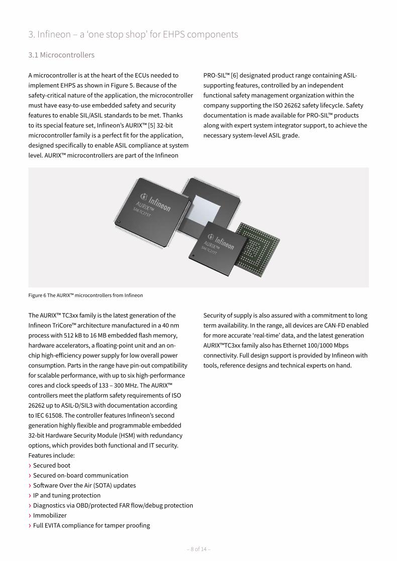
A microcontroller is at the heart of the ECUs needed to implement EHPS as shown in Figure 5. Because of the safety-critical nature of the application, the microcontroller must have easy-to-use embedded safety and security features to enable SIL/ASIL standards to be met. Thanks to its special feature set, Infineon’s AURIX™ [5] 32-bit microcontroller family is a perfect fit for the application, designed specifically to enable ASIL compliance at system level. AURIX™ microcontrollers are part of the Infineon
PRO-SIL™ [6] designated product range containing ASIL-supporting features, controlled by an independent functional safety management organization within the company supporting the ISO 26262 safety lifecycle. Safety documentation is made available for PRO-SIL™ products along with expert system integrator support, to achieve the necessary system-level ASIL grade.
The AURIX™ TC3xx family is the latest generation of the Infineon TriCore™ architecture manufactured in a 40 nm process with 512 kB to 16 MB embedded flash memory, hardware accelerators, a floating-point unit and an on-chip high-efficiency power supply for low overall power consumption. Parts in the range have pin-out compatibility for scalable performance, with up to six high-performance cores and clock speeds of 133 – 300 MHz. The AURIX™ controllers meet the platform safety requirements of ISO 26262 up to ASIL-D/SIL3 with documentation according to IEC 61508. The controller features Infineon’s second generation highly flexible and programmable embedded 32-bit Hardware Security Module (HSM) with redundancy options, which provides both functional and IT security. Features include:
› Secured boot
› Secured on-board communication
› Software Over the Air (SOTA) updates
› IP and tuning protection
› Diagnostics via OBD/protected FAR flow/debug protection
› Immobilizer
› Full EVITA compliance for tamper proofing
Security of supply is also assured with a commitment to long term availability. In the range, all devices are CAN-FD enabled for more accurate ‘real-time’ data, and the latest generation AURIX™TC3xx family also has Ethernet 100/1000 Mbps connectivity. Full design support is provided by Infineon with tools, reference designs and technical experts on hand.
Figure 6 The AURIX™ microcontrollers from Infineon

– 9 of 14 –
3.2 Safety power supplies
A microcontroller is only as safe as its power supply, so Infineon offers the TLF35584 multiple output, system power supply chip, part of the PRO-SIL™ range [7]. The ISO 26262-compliant part enables system design up to ASIL-D with multiple user-protected safety features such as rail monitoring, failure detection with a flexible watchdog concept and a ‘safe state’ controller which provides secondary safety paths. Built-in test is included to ensure that all features are operating correctly. The device has a maximum input of 40 V so a pre-regulator is needed
when powered from a 24 V truck supply which, according to standard LV124, can peak at 60 V. This can be a simple linear, active regulator but efficiency suffers. A better solution is the Infineon low-cost, automotive-qualified TLE6389xx active DC-DC pre-regulator which delivers flexibility and efficiency with a fixed or adjustable output [8]. The device has under-voltage monitoring on input and output and very low quiescent and shutdown current. Figure 7 shows how the TLF35584 and TLE6389xx interface to the AURIX™ microcontroller.
Figure 7 TLF35584 and TLE6389 powering an AURIX™ microcontroller
~60 V
DC-DCTLE6389xx~60 V
40 Vmax
Activeclamping
AURIX™
VEXT
TLF35584
Voltagemonitor
MCU errormonitor
Watchdog
Safestate
controlSMU-FSP
PORST
GPIO or SPI

– 10 of 14 –
3.3 MOSFET gate drivers
In an EHPS system, motors are activated to apply steering torque or to drive a hydraulic pump. The motor drive switches are typically MOSFETs in a three-phase bridge arrangement which interfaces to the ECU microcontroller via a driver. To address the CAV market and a wide range of 24 V applications, Infineon is currently developing automotive-qualified 60 V MOSFETs in small leadless packages.
These will complement existing automotive-qualified products including the Infineon ISO 26262-compliant TLE9180D-31QK, a 3-phase driver that is matched to
the AURIX™ microcontroller with detailed diagnostics and protection features (Figure 8) [9]. Monitoring is included for short circuits, under and over voltage, over-temperature and supply voltage failure. The device can be configured after power-up with an integrated Serial Peripheral Interface (SPI) which can be used to adjust failure behaviour, threshold voltages and filter times for the supervisory functions. Supply rails can be 12, 24 or 48 V nominal with each output channel able to support typically 2 A drive. A ‘limp-home’ mode maintains a minimum functionality in the event of component failure.
Figure 8 The Infineon TLE9180D-31QK three-phase motor driver
PFBx
VS
Diagnostic logicShort circuit UndervoltageOvervoltage
OvertemperatureReset
VCC failure
Input logicShoot-through protection
DeadtimeIHx
Half-bridge driver stage
Short circuit protectionFloating driver stage
Half-bridge driver stage
Short circuit protectionFloating driver stage
Half-bridge driver stage
Short circuit protectionFloating driver stage
VDHx
VCC voltage check
GHx
SHxILx
VRO
ERR
2x/3xcurrent sense
OpAmp
ISPx
ISNx
AGND GND CP_GNDAGNDVOx
INH
ENAVCC
APC
BHxCL1 CH1 CB1 CL2 CH2
Power supplywith diagnostic and safety functions
VDHP
SPI interfaceMOSI
CLK_SPI
CSN
MISO
SOFF
– 11 of 14 –
3.4 Automotive-grade MOSFETs
IInfineon is a global leader in the world of automotive MOSFETs, with more than ten billion MOSFETs sold since 2010 and with 2.3 billion parts shipped in 2018 alone. Quality remains pivotal in the development and manufacturing of products, and as a result the field-return rate for automotive MOSFETs currently lies below 0.1 ppm. Infineon has a wide portfolio of 80 V MOSFETs suitable for EHPS applications, like the OptiMOS™ 5 80 V, automotive-grade IAUS165N08S5N029 or IAUT165N08S5N029 products [10]. The portfolio combines the best-in-class OptiMOS™ 5 frontend technology with a variety of packages for different purposes. For instance, the robust, 10x12 mm2 leadless
TOLL package is ideal for high current applications on FR4 or copper-based IMS boards. And for enhanced board-level reliability, the leaded 10x12 mm2 TOLG package has been designed specifically for aluminum-core IMS boards. Additionally, the 5x6mm2 SSO8 package variant offers an even smaller footprint, providing scalability according to different current and power requirements. To further cater to the CAV market and to address a wider range of 24 V applications, Infineon is also currently developing new, automotive-qualified 60 V MOSFETs in small leadless packages.
3.6 Sensors
In EHPS systems, various parameters must be sensed including current, mechanical angle and torque of the steering wheel and rotor position in motors.Current and torque in an EHPS can be sensed accurately with the ISO 26262-compliant Infineon XENSIV™ TLE499x range of Linear Hall-effect sensors [12]. These devices have built-in redundancy with two channels; ‘main’ and ‘sub’, each with separate signal paths within the chip. Compliance with ASIL-D can be achieved thanks to a high degree of diagnostics coverage and data security, with cyclic redundancy and rolling counter checks on the digital outputs. The devices are in a 3-pin leadless package for mounting in PCB-less modules.Angle sensors in the Infineon TLE5014D and fully-redundant TLE5012BD ranges use the ‘Giant Magneto Resistance’ (GMR) effect with a maximum error of 1.0° over lifetime and temperature (with activated auto-calibration).
The sensors detect magnetic field orientation, sine and cosine angle, to interpret angular position, revolution count and speed parameters. Two channels are incorporated in each device which can be used for redundancy and the parts can be configured and diagnostics/status information retrieved over an SPI-compliant bidirectional communications link. Diagnostics coverage is greater than 97 percent for each channel enabling ASIL-D compliance.Rotor position sensor TLE5309D from Infineon also uses a GMR sensor for 360° coverage along with an Anisotropic Magneto Resistance (AMR) sensor for high precision (180° coverage). The sensors can be combined into a redundant design with the die physically separated in the package and with separate supply pins. The output is analog and the device features low current consumption and fast start-up.
3.5 Connectivity
If the microcontroller is the ‘brain’ of an ECU, the CAN bus is the nerve connection to sensors and actuators, providing communications for control and monitoring. Automotive-qualified CAN bus transceivers are available from Infineon; types TLE7251V, TLE7250V and TLE9251V1 [11]. The parts are CAN FD-compliant and versions are available that are pin-out compatible with older non-compliant types,
allowing for easy upgrade. For new space-constrained designs, a version is available in the tiny TSON-8 package with a ‘lead tip inspection’ feature, enabling automated optical inspection to be used. CAN FD up to 2 Mbit/s is supported and the parts are fully ruggedized with an extended supply range and high immunity to EMI, ESD and automotive transients.
– 12 of 14 –
4. Conclusion
Infineon has a long history in vehicle electronics applications and is at the forefront of developing technologies that will ultimately lead to fully autonomous vehicles. Parts available meet the requirements of today’s markets with a program of development anticipating future needs and specifications. Electro-Hydraulic Power Steering (EHPS) is an example where Infineon offers parts for a complete solution today, from microcontrollers through sensors and communications to motor drivers and power switches, all automotive-qualified and ready to be designed
into the highest ASIL grade systems.Reducing the total cost of ownership (TCO) is becoming vital for the CAV market to ensure greater cost savings in conjunction with greater levels of automation. Infineon focuses on reliable and efficient solutions, not only by offering the largest product portfolio for the CAV market but also by offering complete system solutions to meet all individual requirements, making it a true “one-stop shop” for CAV.
Figures
Figure 1 Trends in commercial, construction 3 agricultural vehicles
Figure 2 Levels of driving automation – 4 source: SAE J3016
Figure 3 Features available with 5 increasing automation levels
Figure 4 Possible variants of EHPS for 6 commercial vehicles
Figure 5 Level 2 Electro-Hydraulic 7 Power Steering (EHPS)
Figure 6 The AURIX™ microcontrollers 8 from Infineon
Figure 7 TLF35584 and TLE6389 powering 9 an AURIX™ microcontroller
Figure 8 The Infineon TLE9180D-31QK 10 three-phase motor driver

– 13 of 14 –
5. References
[1] Advanced driver assistance systems for trucks – benefit estimation from real-life accidents; Kuehn, Hummel and Bende; German Insurers Accident Research. Paper 11-0153
[2] SAE International, 2016. J3016™. Surface vehicle recommended practice – Taxonomy and definitions for terms relating to driving automation systems for on-road motor vehicles
[3] ISO 26262 ‘Road vehicles – Functional safety’[4] IEC 61508 ‘Functional safety of electrical/electronic/programmable electronic safety-related systems’ [5] https://www.infineon.com/dgdl/Infineon-TriCore_Family_BR-BC-v01_00-EN.pdf?fileId=5546d4625d5945ed015dc81f-
47b436c7[6] https://www.infineon.com/cms/en/product/microcontroller/safety-products-pro-sil/[7] https://www.infineon.com/dgdl/Infineon-TLF35584_ProductBrief-PB-v01_00-EN.pdf?fileId=5546d46266f-
85d63016711a0d29f2713[8] https://www.infineon.com/dgdl/Infineon-TLE6389-DS-v02_20-EN.pdf?fileId=5546d46258fc0bc1015969d25b5241c7[9] https://www.infineon.com/dgdl/Infineon-TLE9180D-31QK-DataSheet-v01_00-EN.pdf?fileId=5546d4626afcd350016b2d-
7bab057342[10] https://www.infineon.com/dgdl/Infineon-Productbrief_PowerMOSFET_OptiMOS5_80V_100V-PB-v01_00-EN.pdf?file-
Id=5546d4624b0b249c014b54c00473655e[11] https://www.infineon.com/cms/en/product/transceivers/automotive-transceiver/automotive-can-transceivers/[12] https://www.infineon.com/dgdl/Infineon-Sensor_Solutions_BR-2019_13062019-ProductSelectionGuide-v01_00-EN.
pdf?fileId=5546d462636cc8fb0164229c09f51bbe

Service hotline
Infineon offers its toll-free 0800/4001 service hotline as one central number, available 24/7 in English, Mandarin and German.
› Germany .................... 0800 951 951 951 (German/English)
› China, mainland ....... 4001 200 951 (Mandarin/English)
› India .......................... 000 800 4402 951 (English)
› USA ............................ 1-866 951 9519 (English/German)
› Other countries ......... 00* 800 951 951 951 (English/German)
› Direct access ............. +49 89 234-0 (interconnection fee, German/English)
* Please note: Some countries may require you to dial a code other than “00” to access this international number. Please visit www.infineon.com/service for your country!
Where to buy
Infineon distribution partners and sales offices: www.infineon.com/WhereToBuy
Published by Infineon Technologies AG81726 Munich, Germany
© 2019 Infineon Technologies AG.All rights reserved.
Date: 08 / 2019
Please note!THIS DOCUMENT IS FOR INFORMATION PURPOSES ONLY AND ANY INFORMATION GIVEN HEREIN SHALL IN NO EVENT BE REGARDED AS A WARRANTY, GUARANTEE OR DESCRIPTION OF ANY FUNCTIONALITY, CONDITIONS AND/OR QUALITY OF OUR PRODUCTS OR ANY SUITABILITY FOR A PARTICULAR PURPOSE. WITH REGARD TO THE TECHNICAL SPECIFICATIONS OF OUR PRODUCTS, WE KINDLY ASK YOU TO REFER TO THE RELEVANT PRODUCT DATA SHEETS PROVIDED BY US. OUR CUSTOMERS AND THEIR TECHNICAL DEPARTMENTS ARE REQUIRED TO EVALUATE THE SUITABILITY OF OUR PRODUCTS FOR THE INTENDED APPLICATION.
WE RESERVE THE RIGHT TO CHANGE THIS DOCUMENT AND/OR THE INFORMATION GIVEN HEREIN AT ANY TIME.
Additional informationFor further information on technologies, our products, the application of our products, delivery terms and conditions and/or prices, please contact your nearest Infineon Technologies office (www.infineon.com).
WarningsDue to technical requirements, our products may contain dangerous substances. For information on the types in question, please contact your nearest Infineon Technologies office.
Except as otherwise explicitly approved by us in a written document signed by authorized representatives of Infineon Technologies, our products may not be used in any life- endangering applications, including but not limited to medical, nuclear, military, life-critical or any other applications where a failure of the product or any consequences of the use thereof can result in personal injury.
Mobile product catalogMobile app for iOS and Android.
www.infineon.com