introduction to steering systems - calex uk ltd · introduction to steering systems . 2 ......
TRANSCRIPT

Introduction to Steering Systems

2
Course Objectives
On completion of this course you will be expected to effectively:
• Identify and understand the fundamental principles of steering system
• Identify and understand the main components used in the manual steering system
• Identify and understand the different steering gear systems used
• Identify and understand the operating principles of hydraulic power assisted steering
• Indentify and understand the components used in hydraulic
power assisted steering
• Indentify and understand the operating principles and
benefits of electro/hydraulic power assisted steering
• Identify and understand the benefits of active and
passive steering/suspension systems
• Identify and understand the importance of inspection
and maintenance of the steering system

3
The steering system of a vehicle allows the driver to control the direction of the vehicle through a system
of gears and linkages that connects the steering wheel with the front wheels.
Steering Systems - Introduction
The steering system must perform these functions:
• Change direction of vehicle
• Provide a degree of 'feel' of the road for the driver
• Not transmit excessive shock back to the driver
due to an uneven road
• Not cause excessive tyre wear
Early vehicles used manual steering linkage system,
manual steering boxes or manual racks.
Later systems used the benefits of hydraulic fluid
systems to greatly improve the steering performance.
Today, we now have fully electronically controlled steering systems
for greater and smoother performance and maneuverability.

4
When turning a corner, the driver turns
a steering wheel.
This turning motion is transferred to the
front road wheels.
The direction the front wheels point is
the direction the car will travel, so long
as the wheels do not lose grip.
Steering Systems - Introduction

5
The main purpose of the steering wheel is to provide the driver
with a suitable amount of leverage to turn the steering from
side to side with a minimal amount of effort.
Early designs of steering wheels were primitive in design
and only normally had a horn button mounted in the
centre hub of the wheel.
With the development of safety restraints and additional
driver functionalities for audio control and cruise control.
Steering Systems - Steering Wheel
The steering wheel has become a very sophisticated
and multi-functional assembly.
With an restraints air bag mounted in the centre hub
of the wheel to protect the driver in frontal and
severe impacts and a series of multi-functional
buttons to enable the driver to operate a multitude
of systems without their hands leaving the steering wheel.

6
The steering column is a device intended primarily
for connecting the steering wheel to the steering
mechanism and allows the transfer of the
driver's input torque from the steering wheel.
Steering Systems - Steering Column
In addition to this, the steering column provides a
suitable location for multi-functional switches
either side of the steering wheel.
A location for a steering lock to secure the
steering in a parked position.
Steering Column - Upper Section

7
Also the column can have manual or electronic adjustment
which allows the driver to adjust the height and length of
the column to their preferred comfort position.
• Tilting the column adjusts the angle of
the steering wheel
• Sliding the column in and out adjusts the reach
(the distance of the steering wheel to the driver)
Steering Systems - Steering Column
Steering Column - Upper Section
8
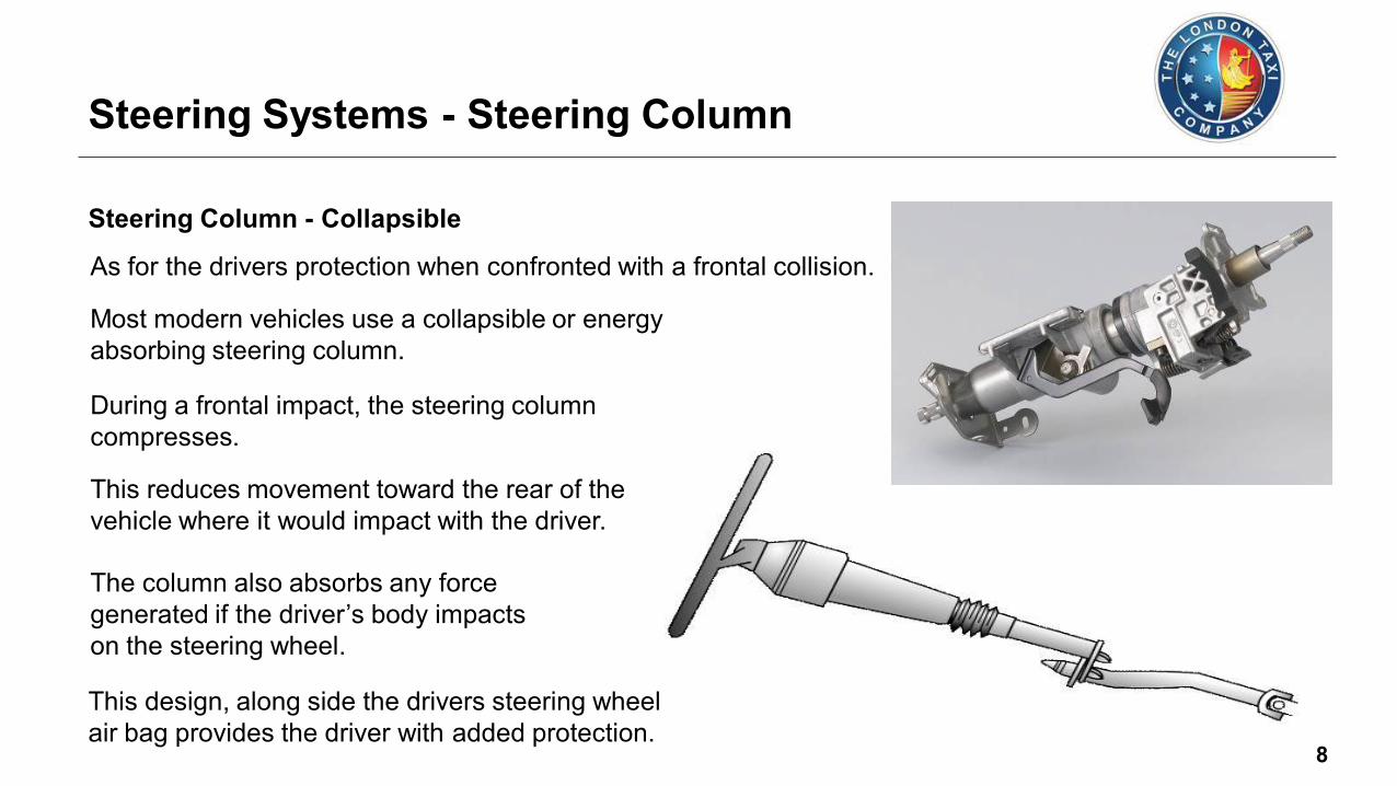
As for the drivers protection when confronted with a frontal collision.
Most modern vehicles use a collapsible or energy
absorbing steering column.
The column also absorbs any force
generated if the driver’s body impacts
on the steering wheel.
During a frontal impact, the steering column
compresses.
This reduces movement toward the rear of the
vehicle where it would impact with the driver.
Steering Systems - Steering Column
This design, along side the drivers steering wheel
air bag provides the driver with added protection.
Steering Column - Collapsible

9
There are three main types of
collapsible steering column:
Universal Joint
Split Column
Telescopic
Steering Systems - Steering Column
Steering Column - Collapsible

10
The lower section of the steering column is
designed to absorb road wheel shock
when driving with using rubber couplings.
Also the lower column will have a universal
joint located in the upper and lower sections.
Steering Systems - Steering Column
This is to allow for the different relationship
between steering rack and column, when
manoeuvring from lock to lock, as well
as allowing the rack to move on impact.
Within the upper section of the assembly
there will be a compression joint that is
designed to collapse on impact.
Steering Column - Lower Section

11
Universal joints allow the steering shaft to change angles.
Most steering columns are designed with a
collapsible section that helps prevent the
forces generated in an accident being
transferred to the driver.
The bottom of the steering shaft
connects to the steering
components
(rack or box).
Universal Joints
Connection to
Steering Components
Collapsible
Section
Lower Steering
Shaft
Steering Wheel
Steering Systems - Steering Column
Steering Column - Lower Section

12
The steering gearbox provides the driver with a lever system to enable them to exert a
large force at the road wheel with the minimum effort, and to control the
direction of vehicle motion accurately.
The overall ratio between the steering wheel
and the road wheel varies from about 18 : 1
to 35 : 1, depending on the load on the
road wheels and the type of steering.
Steering Systems - Steering Gear System
13
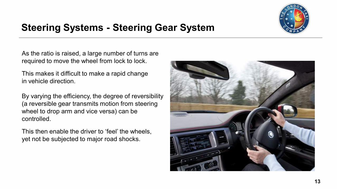
As the ratio is raised, a large number of turns are
required to move the wheel from lock to lock.
This makes it difficult to make a rapid change
in vehicle direction.
Steering Systems - Steering Gear System
By varying the efficiency, the degree of reversibility
(a reversible gear transmits motion from steering
wheel to drop arm and vice versa) can be
controlled.
This then enable the driver to ‘feel’ the wheels,
yet not be subjected to major road shocks.

14
A number of different types of steering gear systems have
been used over the years.
They are classified into two groups. They are as follows:
• Steering box types
• Rack-and-pinion types
Steering Systems - Steering Gear System

15
Sometime identified as the linkage steering system.
Lower Steering
Column Shaft
(With Universal Joints) Steering Box
Pitman Arm
Drag Link
(Centre Link)
Steering Systems - Layouts
Track Rod End
Ball Joint
Track Rod Arm
Idler Arm
Assemblies
The steering column shaft is coupled
through a steering gearbox to a
‘Pitman arm’ that moves to drive
the centre link and wheels,
guided by the idler arms.
Steering Box

16
Hub
Carrier
Rack Housing
Gator (Boot)
Track Rod Arm
Steering Gear
(contains pinion)
Track Rod End
Ball Joint
Steering Systems - Layouts
Rack & Pinion Steering
Compare this with rack and pinion
steering layout, where a pinion
wheel turns on a toothed rack
to move a steering bar
horizontally.

17
The steering box is commonly used in larger vehicles,
such as commercial-type vehicles.
Although some manufacturers of four-wheel drive
vehicles use this system due to its strength.
Steering Systems - Steering Box System
There are a number of different types of steering
box used, which include:
• Worm and Sector
• Screw and Nut
• Recirculating Ball
• Cam and Peg
• Worm and Roller
All of the steering box named above are identified
by their internal mechanical design.
All of them operate by either their mechanical structure or are supported by the
means of a hydraulic fluid system to enhance their performance.

18
The steering box converts
rotation of the steering shaft
into angular movement of the
‘Pitman arm’.
The box is partially filled with
oil to lubricate the steering
mechanism inside.
The steering shaft turns a worm
shaft that runs through a
threaded nut.
The nut has teeth that engage
with the teeth on a sector gear.
Steering
Box Mounting
Points
Chassis
Oil Level
Plug Oil
Worm Shaft
Sector
Gear
Nut
Worm Shaft
Support
Bearing
Steering Shaft
Pitman Arm
Steering Systems - Steering Box Operation

19
In this type of steering box, the end of the shaft
from the steering wheel has a worm gear
attached to it.
It meshes directly with a sector gear (so called,
because it's a section of a full gear wheel).
Steering Systems - Worm & Sector Steering Box
When the steering wheel is turned, the shaft
turns the worm gear, and the
sector gear pivots
around its axis as
its teeth are moved
along the worm gear.

20
The sector gear is mounted on the cross shaft which
passes through the steering box and out the
bottom where it is splined, and the pitman
arm is attached to the splines.
When the sector gear turns, it turns the
cross shaft, which turns the pitman arm,
giving the output motion that is fed into
the mechanical linkage on the track rod.
Steering Systems - Worm & Sector Steering Box
The box itself is sealed and filled with
oil or grease.
Worm
Sector
Connection to
Pitman Arm Shaft
Tapered Roller
Bearing
Tapered Roller
Bearing
Adjusting
Nut
Filler Plug
Steering Shaft
(Input)

21
As the driver turning the steering wheel
it makes the worm shaft turn.
The worm shaft acts as a screw, and
the nut rides up and down as the
screw turns.
This in turn rotates the sector gear shaft,
because the teeth on the nut are meshed
with the teeth on the sector gear.
Worm Shaft
Nut
Sector Gear Shaft
Steering Systems - Worm & Sector Steering Box
The diagram shows the active components
that are present inside the worm and sector
steering box.

22
The screw and nut type mechanism is possibly the basic form
for all the other types of steering gear box mechanisms.
A nut is screwed on a multi-start thread formed
on the inner column.
This design gives much more strength to
the main shaft.
Steering Systems - Screw & Nut Steering Box
When the steering wheel is turned, the splined
end rotates causing the thread section to
rotate too, but because the nut is prevented
from turning the ball joint has to move up
and down with the thread instead.
This movement then causes the rocker
shaft to eventually transmit movement
to the steering linkage and onto the
road wheels.
Screw
Nut
Ball Joint Rocker Shaft
Bearing
Bearing
End Float
(Adjuster)
Steering
Input Shaft

23
In a recirculating ball steering box, the worm
drive has many more turns on it with a
finer pitch.
Steering Systems - Recirculating Ball Steering Box
A box or nut is clamped over the worm drive
that contains dozens of ball bearings.
These loop around the worm drive and then
out into a recirculating channel within the nut
where they are fed back into the worm
drive again.
Rocker Arm
Pitman Arm
Worm Gear
Recirculating
Ball Bearings
Steering
Input Shaft
Ball Nut Rack

24
Steering Systems - Recirculating Ball Steering Box
This system has much less free play or
slack in it than the other designs, hence
why it's used the most.
The example shows the mechanism
with the nut shown in cutaway, so
you can see the ball bearings and
the recirculation channel.

25
Worm Shaft
Sector Gear
Shaft
Balls and
Guides
Ball Nut
Steering Systems - Recirculating Ball Steering Box
As the steering wheel is turned, the worm drive
turns and forces the ball bearings to press
against the channel inside the nut.
This forces the nut to move along the worm drive.
The nut itself has a couple of gear teeth cast
into the outside of it and these mesh with
the teeth on a sector gear which is attached
to the cross shaft just like in the worm and
sector mechanism.

26
Worm Gear Adjuster
The adjuster sets the pre-load on the thrust
bearings that locates the worm shaft.
Worm gear preload is needed to prevent
free play in the steering that would allow
the vehicle to wander.
The lubricant for the steering gear
is kept in place with seals.
Worm Shaft Sector Gear
Sector Gear Shaft
Lip Oil Seal Sector Gear Shaft
Adjustment Screw
The sector gear shaft has ball or roller
bearings to reduce friction.
Steering Systems - Recirculating Ball Steering Box

27
A tapered peg in the rocker arm engages with a
special cam formed on the inner column.
The end-float of the column is controlled by
shims, and an adjusting screw on the side
cover governs the backlash and
end-float of the rocker shaft.
Steering Systems - Cam & Peg Ball Steering Box
A modified form, known as the high
efficiency cam and peg gear, uses
a peg, which is allowed to rotate
in bearings in the rocker arm.

28
Steering Systems - Cam & Peg Ball Steering Box
Adjusting Screw
Lock Nut
Side Plate
Rocker Shaft
Pitman Arm (Drop Arm)
Lock Nut
Peg Cam
Lock Nut
Adjusting Screw
Filler Plug
Input Shaft
Adjuster Lock Nut
Housing
Base Plate
Output Shaft

29
Steering Systems - Worm & Roller Steering Box
The roller is mounted on a roller bearing
shaft and is held captive on the end of
the cross shaft.
The worm and roller steering box is similar in
design to the worm and sector box.
The difference here is that instead of having
a sector gear that meshes with the worm
gear, there is a roller instead.

30
As the worm gear turns, the roller is forced to
move along it but because it is held captive
on the cross shaft, it twists the cross shaft.
Typically in these designs, the worm gear
is actually an hourglass shape so that
it is wider at the ends.
Steering Systems - Worm & Roller Steering Box
Without the hour glass shape, the roller
might disengage from it at the extents
of its travel.
Input Shaft Roller Bearing
Roller Bearing
Housing
Output Shaft
Roller
Worm

31
Rack-and-pinion steering is more precise
and compact than conventional steering
systems, mainly due to the fact it uses
fewer component parts and has a
more direct path to the wheels.
Rack-and-pinion steering systems are the most
common type of steering found on modern
cars and small commercial vehicles.
Steering Systems - Rack & Pinion Steering
The rack is contained in a metal
housing and bolted to the vehicle
body frame or sub-frame using
either U-shaped brackets or
bolt-through brackets on
the housing.

32
Rack
Pinion Shaft Housing
Pinion
Steering Systems - Rack & Pinion Steering
At the base of the steering column there is a
short pinion shaft (gear wheel) located within
the steering rack housing.
The pinion gear teeth mesh with a
series of teeth that are located on
a long shaft which is located
longitudinally within the
housing and is known
as the rack.

33
Pinion Gear
Rack
Steering Systems - Rack & Pinion Steering
The pinion gear meshes very closely
to the teeth of the rack.
This helps minimises any backlash
within the gear mechanism, minimises
any wear and provides the driver with
very precise steering feel.
Changing a rotary motion of the pinion
gear into linear motion of the rack.
Moving the steering wheel from side to
side rotates the pinion shaft and in
turn moves the rack shaft.
34
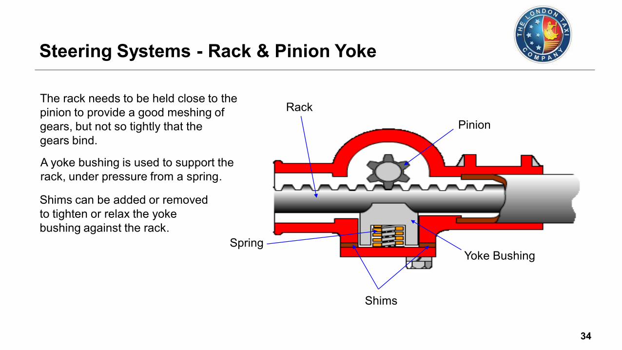
The rack needs to be held close to the
pinion to provide a good meshing of
gears, but not so tightly that the
gears bind.
A yoke bushing is used to support the
rack, under pressure from a spring.
Shims can be added or removed
to tighten or relax the yoke
bushing against the rack.
Pinion
Spring
Shims
Yoke Bushing
Rack
Steering Systems - Rack & Pinion Yoke

35
Some manufacturers use an adjuster
plug, rather than shims, to force the
spring and therefore the yoke
bushing, against the rack.
Manufacturers set this according to
specifications to control steering
harshness, noise and feedback.
This adjustment is called the rack
preload or yoke lash.
Pinion
Spring
Adjuster Plug Yoke Bushing
Locknut
Rack
Steering Systems - Rack & Pinion Yoke

36
The track rod arm is the component that links the
main steering shaft (Rack) to the outer track rod
ends on either side of the vehicle.
Track Rod Arm
Gaiter
The arm is designed to allow for steering and
suspension movement.
This is achieved by the use of a swivel joint
located in the inner section of the arm.
Steering Systems - Track Rod Arm
Swivel Joint

37
At the other end of the arm you will identify
that the shaft is threaded.
This is to allow the track rod end to be
connected to the arm and also
to allow for adjustment of the
steering front toe.
The arm is secured to the main rack shaft by
means of a threaded interlock.
Steering Systems - Track Rod Arm
Internal
Threaded
Interlock
External
Threaded
Interlock

38
Steering rack gaiters are a pleated rubber tubed design.
Secured at either end by retaining
straps, they allow for steering arm
movement depending on suspension
and steering demands.
Rotating the steering from lock
to lock the gaiters expand and
retract, maintaining their position
and protection of the steering
inner joints and seals.
Mounted on each side of the steering
rack, they are designed to protect
the steering rack inner joints and
mechanism from any road dirt
and water.
Steering Systems - Rack Gators
Gaiter

39
The track rod ends are located on either ends of
steering rack arms and are designed to allow
for angular and rotational movement of
the steering and suspension.
The joints are similar in design to a ball joint
but has an internal or external threaded
section that when located, interlocks with
the track control arms.
Steering Systems - Track Rod End (Ball Joints)
Early designed ball joints had a additional
grease nipple located in to the base of the
assembly.
Regular greasing was required
to maintain and prolong the
service life of the joint. Grease Nipple

40
On assessing the design at the ball joint
end, the joint has a tapered and threaded
pin shaft/pin at one end and a ball shaped
knuckle at the other end.
The knuckle joint end is located within a
plastic, spring-loaded seat.
In-cased within the metal housing and
protected by a plastic bush located on
the top of the joint and sealed with a
rubber dust cover and retaining ring.
The ball knuckle joint is made from
heat-treated steel to give strength
and a clean finish.
Steering Systems - Track Rod End (Ball Joints)
Moulded Plastic
Bushing with
Compression Spring
Moulded
Plastic
Bushing
Moulded
Plastic
Bushing
Moulded Plastic
Bushing without
Compression Spring
Angular Movement
(Possible each side of centre)

41
The rubber dust cover is designed to keep out
any dirt or moisture also retains the pre-packed
grease within the joint housing.
The joint is pre-packed and seal for its life.
At the other end of the joint is the end that
connects to the track control arm.
Depending on design determines the fitment
to the track arm.
Securing the joint to the arm would be
achieved by a lock-nut that secures
the joint to the shaft.
At the ball joint end, the joint is secured to
the hub steering arm by a nylon lock-nut
or a castle-nut and split pin.
Steering Systems - Track Rod End (Ball Joints)

42
To adjust the vehicles steering toe
angle and to align the steering
wheel, the track rod ends are
adjusted equally to their required
position and secured in place.
This is just one of a number of
adjustment procedures that must
be accurately set up if the vehicle
is to steer correctly and minimise
any abnormal tyre wear.
Steering Systems - Track Rod End (Ball Joints)
Incorrect Toe In
Incorrect Toe Out
43
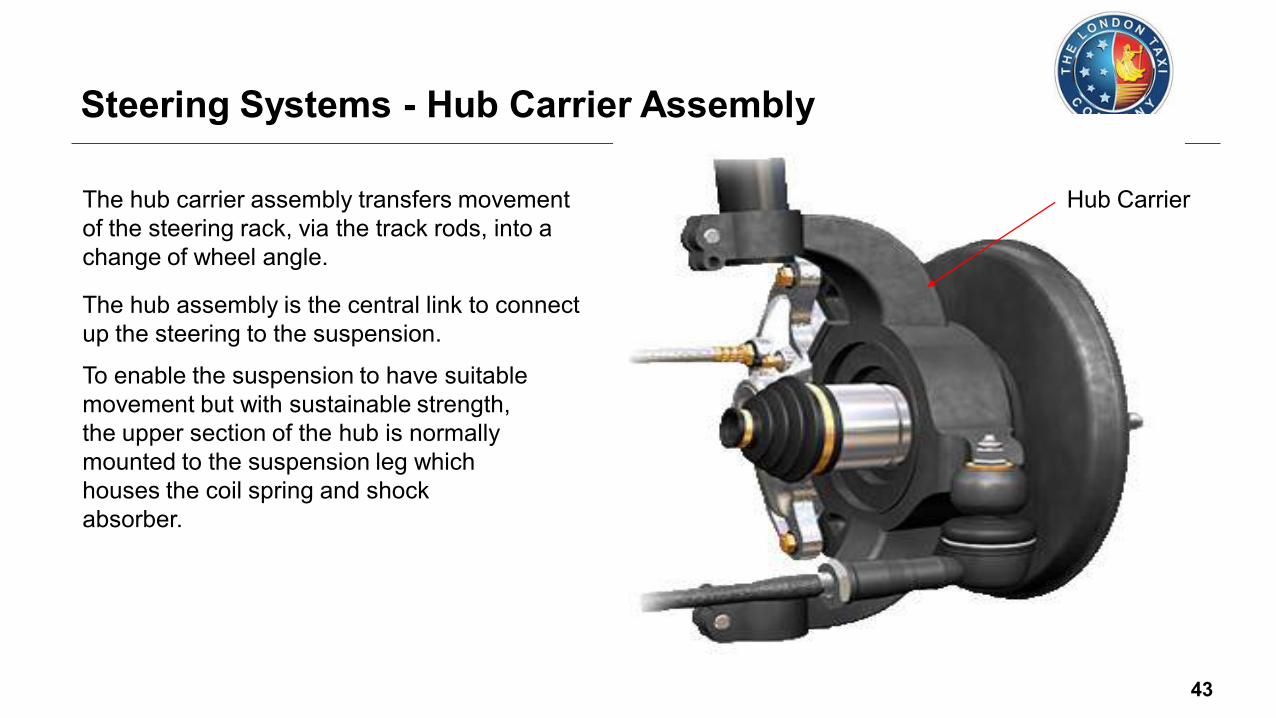
The hub carrier assembly transfers movement
of the steering rack, via the track rods, into a
change of wheel angle.
The hub assembly is the central link to connect
up the steering to the suspension.
Hub Carrier
To enable the suspension to have suitable
movement but with sustainable strength,
the upper section of the hub is normally
mounted to the suspension leg which
houses the coil spring and shock
absorber.
Steering Systems - Hub Carrier Assembly

44
The lower section of the hub is then connected
via the lower ball joint which is normally part of
the lower suspension arm.
The hub carrier assembly also supports the
brake disc, caliper and the road wheel via a
centralised wheel bearing and hub flange.
Steering Systems - Hub Carrier Assembly

45
On a linkage type steering system
layout where it utilises the usage
of a steering box, there are some
additional components used:
Idler Arm
Bracket
Track Rod
Sleeve Adjuster
Centre Link
Idler Arm
Steering
Damper
Pitman
Arm
Track Rod
Sleeve Adjuster
Steering Systems - Linkage Type Steering

46
Movement from the steering box is coupled and
transmitted through to a steering arm known as
a ‘Pitman arm’ which in turn then moves to drive
the centre link (drag link) and wheels, guided by
an idler arm.
Steering Systems - Pitman Arm

47
With using a Pitman arm within the linkage
type steering system, usually uses a worm
drive on the steering shaft.
A Pitman arm transforms the rotary
movement into a horizontal movement
at the linkages.
Only a small number of teeth are
needed on the Pitman arm cog wheel.
The practical type shown in this diagram
uses a re-circulating ball bearing
mechanism.
Pitman
Arm
Pitman
Arm
Steering Systems - Pitman Arm
Steering Box

48
An idler arm keeps the steering centre link parallel to
the front axle and prevents any unwanted flexing of
steering component parts.
One end is attached to the vehicle frame and the
other end to the centre link (drag link).
The idler arm operates in tandem with the Pitman arm.
The idler can also act
as a damper but does
not affect the overall
steering movement.
Steering Systems - Idler Arm
49
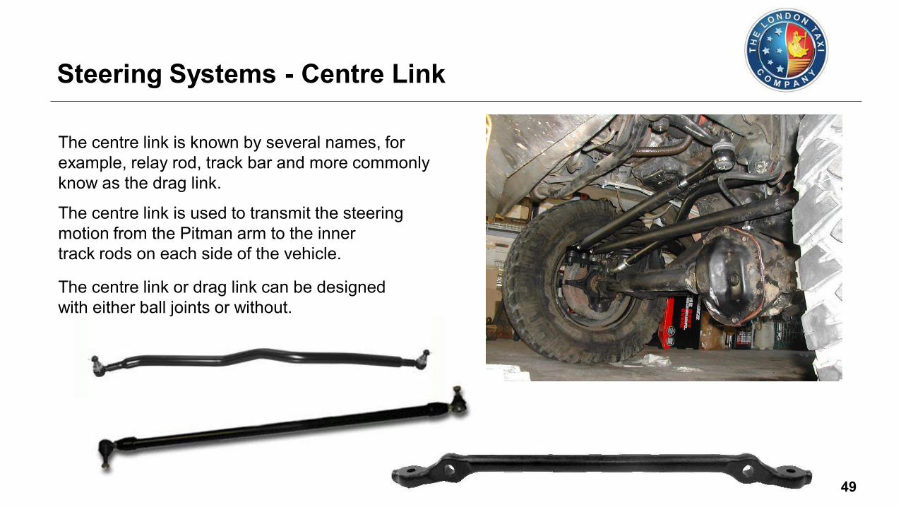
The centre link is known by several names, for
example, relay rod, track bar and more commonly
know as the drag link.
The centre link is used to transmit the steering
motion from the Pitman arm to the inner
track rods on each side of the vehicle.
Steering Systems - Centre Link
The centre link or drag link can be designed
with either ball joints or without.

50
Some vehicles have a hydraulic damper
installed between the centre link and
the frame or axle.
The damper absorbs road shocks in the
steering system and prevents steering
wobble at higher road speeds.
A hydraulic piston inside allows
small amounts of hydraulic
fluid to pass through
calibrated holes to
absorb shock energy.
Stub Axle Front
Axle
Front
Hydraulic
Damper
Assembly Centre link
(Drag Link)
Steering Systems - Linkage Damper

51
The track rod assembly contains an adjuster
sleeve with internal left hand and right
hand threads.
At each end of the assembly is a
track rod ball joint.
Sleeve
Clamp
Clamp Bolts
Track Rod
Steering Systems - Adjustable Sleeve Track Rod

52
Power Assisted Steering (PAS) is now common on most vehicles today.
This has been a major advancement from
the early design of manual steering.
Both, steering racks and boxes utilise the
benefits of this assistance.
Some advantages of Power Assisted Steering (PAS) are as follows:
• Minimise driver fatigue by lightening the action of the steering.
This is more evident during parking manoeuvres when the resistance to
turning the steered wheels is greatest.
• Reduce the required number of turns lock to lock
(the gear ratio can be higher than on manual steering).
• Reduce 'kick back' at the steering wheel by counteracting road shocks
• Improve safety by better resisting any sudden swerving of the
vehicle during tyre deflation
• Permit heavier loading of the steered wheels to allow greater freedom in the overall
vehicle design for optimum passenger and cargo space
Power Assisted Steering - Introduction

53
At the heart of many PAS systems is a hydraulic
servo-mechanism.
This operates whenever the resistance to turning
the steering wheel exceeds a predetermined
amount.
It then gives additional effort to assist the
manual operation of the steering and so
reduces steering effort.
Power Assisted Steering - Introduction

54
In the hydraulic system fluid is circulated
around the servo mechanism’s closed
circuit by an engine driven pump.
Power Assisted Steering - Operation
When the steering wheel is turned a
hydraulic valve allows more fluid to
flow to the power cylinder.
This increases the pressure and so
force is applied by the pressure to
either one side or the other side
of the servo piston, which is
connected to the steering
mechanism.
Engine Belt
Driven Pump
Reservoir High Pressure
Feed Pipe
Return Feed Pipe
Pump Supply
(Feed) Pipe
Power Rack
Control Valve

55
The control valve is on the end of
the steering column, inside the
rack housing.
The fluid reservoir can be on the top
of the belt-driven hydraulic pump.
The power cylinder acts directly on the rack
bar within the steering rack housing.
Power Assisted Steering - Operation
The steering gear (typical ratio 15:1
for power steering) is on the end
of the steering column.
Fluid is fed to the power cylinder
via valves, lines and hoses.
Control
Valve
Power Rack
Oil Cooler Reservoir
Engine Belt
Driven Pump
Additional oil cooler to maintain
the fluid operating temperature.

56
The power cylinder contains a piston
which is connected to the rack.
The control valve supplies high pressure fluid to the
appropriate side of the piston to assist the rack in
turning the wheels in the required direction. Rack
Power
Cylinder
Housing
Piston
Seals
Pressure Lines
Control Valve
(Inside Rack
Housing)
There are two fluid ports, one each side of the piston.
Fluid Port
Power Assisted Steering - Operation

57
The pump is usually mounted on the
engine, and driven by a pulley and
drive belt.
Some engine driven pumps had a fluid
reservoir incorporated within its housing.
Alternatively, later systems now
use a combined electrically driven
oil pump and reservoir which can
be mounted on the bulkhead.
Electric
Pump with
Reservoir
Power Assisted Steering - Pump
The operating pressure generated in
a hydraulic power steering system
can be up to 200 bar (3,000 psi),
feeding the control valve within
the rack assembly.
Engine-driven
Pump Engine-driven
Pump
with Reservoir

58
The most common type of power steering
pump is the vane type.
The pulley or motor drives a rotor that sits
eccentrically in a cavity inside the housing.
Vane Pump
Fluid entering the pump is trapped
between spring-loaded vanes and
carried to the exit port.
Similar pumps can use rollers instead
of spring-loaded vanes.
Pump
Housing
Cavity
Rotor
Fluid
in
Fluid
out
Power Assisted Steering - Pump

59
The reservoir can either be built-in to the pump, or remotely mounted via a pipe.
Power Assisted Steering - Reservoir
Pump Remote
Reservoir
Power Rack

60
There are three different types of control valves
used within a power assisted rack and pinion or
steering box assembly.
They are as follows:
• Rotary valve
• Spool valve
• Flapper valve
The power piston uses sealing rings to prevent
any fluid leakage from the power piston itself.
The control valves are used to direct the
pressured oil sent from the power steering
pump to the power piston.
Power Assisted Steering - Control Valves
When the steering wheel is in the straight-ahead
position, the control valve is in the neutral position. Flapper Valve
Spool Valve
Rotary Valve

61
Power Assisted Steering - Control Valves
Torsion Bar
Rotary Valve
Pinion Rack
Rotary Valve Type
To Rack
Right Chamber
To Rack
Left Chamber
To Reservoir / Pump
From Pump
Control Valve Shaft The high pressure fluid generated by the power
steering pump is directed back to the reservoir,
thus keeping the pressure even on each side
of the power piston.
When the steering wheel is turned either to
the right or left, this movement is transferred
to the control valve via the torsion bar, which
connects the two together.

62
As the torsion bar is twisted the control valves redirect
the fluid flow causing power assistance.
The amount of assistance given is proportional to the
amount of twisting force exerted on the torsion bar.
Input
Shaft
Output Shaft
Control
Valve
From Steering Wheel
To Steering
Mechanism
Sensing
Region
Cross Section
Torsion
Bar Fluid
Ports
Power Assisted Steering - Control Valves
Rotary Valve Type

63
In the event of power steering pump failure, the
direct connection between the steering wheel
and the pinion gear via the torsion bar enables
the driver to steer the vehicle.
Although the driver is able to turn the wheels,
the steering will feel very heavy as no
assistance is being given.
Power Assisted Steering - Control Valves
Rotary Valve Type

64
Power Assisted Steering - Control Valves
Control
Valve
Shaft
Torsion Bar
Pinion
Sleeve Valve
Spool Valve
Spool Valve Type
Rack
The spool valve type control valve carries out the
same operation as the rotary valve type.
It redirects the pressurised oil from the power
steering pump to the correct side of the
power piston. From Pump
To Rack
Right Chamber
To Rack
Left Chamber
To Reservoir / Pump Ball
Bearings
Sleeve Valve
Side Plate
The main difference is that the spool valve
moves up and down rather than rotating
like the rotary valve.
The control valve shaft and the pinion
are again connected via a torsion bar,
so if the power steering pump fails,
steering can still be achieved.

65
Power Assisted Steering - Control Valves
Stopper
Spool Valve Type
The spool valve is fitted inside the valve
sleeve and the two are connected
together via two steel balls.
The whole unit is connected to the pinion
gear via two sliding pins.
As the pinion rotates the spool valve rotates
in the same direction but also moves up
and down by approximate 1mm.
The sleeve valve is secured to the pinion
gear via a slide plate and snap ring.
This then stops the sleeve valve from
moving up or down.
Control
Valve Shaft
Torsion Bar
(Internal)
Sleeve Valve Spool Valve
From Pump
To Rack Right Chamber
To Rack Left Chamber
To Reservoir
/ Pump
Spiral Groove
Slide Pin
Ball
Bearings

66
The power steering rack has an integral hydraulic actuator.
The control valve can direct pressurised fluid to either side of a piston.
When the steering wheel is turned, the control valve
detects the steering effort and directs pressure to
help push the steering rack piston along.
Power Assisted Steering - Control Valves

67
The flapper type control valve is used
with the recirculating ball type steering
system found in steering boxes, and
is integral with the torsion bar.
The high pressure oil generated by the
power steering pump is first directed
through to the flapper control valves.
Power Assisted Steering - Control Valves
Flapper Valve Type
Worm Shaft Torsion Bar
Sector
Shaft Cylinder
Piston
Flapper No 1
Flapper No 2
To Reservoir From
Pump
A series of flapper valves control the
direction in which the fluid flows.
Fluid is allowed to flow from the pump to
one side of the power steering piston
and back to the reservoir.

68
Depending on the direction the steering
wheel is turned determines which flapper
valves open to allow fluid to flow and
which other flapper valves stay closed.
The closed flapper valves act as pressure
control valves, controlling the pressure at
the power steering piston.
This is also dependent on the amount of
force generated by the driver turning
the steering wheel.
Power Assisted Steering - Control Valves
Flapper Valve Type

69
Power assisted hoses are constructed and designed to fit within
the confinements of the engine bay/sub-frame area.
Design to operate under extreme
temperatures (+/-) and pressures
depending on driving demands.
Power Assisted Steering - Hoses
Made from layers of high spec synthetic rubber,
and cord to provide additional strength and
durability.
The coupled joints and pre-bent pipes are
commonly made from zinc-dichromate
and plated to resist corrosion.
Combination of metal pipe and rubber,
also minimises operating vibrations.

70
The power steering oil flows through the
radiator matrix whilst the air circulates
through the outer core fins.
Power Assisted Steering - Oil Cooler
The power steering oil cooler is normally located
within the radiator stack.
Positioned at the front of the vehicle to obtain
and maximise the benefits of the forced air
flow when the vehicle is in motion.

71
Benefit of having a oil cooler is if the vehicle
does a lot of towing or is driven in extreme
hot climates.
Also, due to the coolers location, heat
created by the other radiators can
assist in maintaining a good operating
temperature during extreme
cold conditions.
Power Assisted Steering - Oil Cooler
Having a oil cooler assists in maintaining a
good operating temperature.

72
The power steering fluid transfers energy from
the pump to the actuator.
It also lubricates and cools the moving parts.
The system typically holds up to 1 litre of fluid.
Many manufacturers recommend a service
interval where the power steering fluid should
be replaced.
It should not be confused with automatic
transmission fluid (ATF), which is not
compatible with power steering system
components.
Power Assisted Steering - Fluid

73
Alternatively, some reservoirs use a dipstick
to indicate the fluid level.
Some vehicles have a clear reservoir where
the power steering fluid can be seen.
The level should be between the minimum
and maximum indicated levels.
Minimum
Maximum
Dipstick
The fluid level is checked against the markings
on the side of the reservoir.
Power Assisted Steering - Fluid
Check & Top Up

74
The fluid should be either clear, pink, or red
showing good condition.
The colour of the power steering fluid can indicate
if there is a problem.
It is common for power steering fluid to turn orange.
If it is very dark or has a burned smell then
it will need replacing.
Power Assisted Steering - Fluid
Check & Top Up

75
Inspection and maintenance of the steering system is just as important as any other vehicle system.
The steering system has to meet manufacturing and governing standards.
Whether the steering is non-assisted or assisted power steering there are a many mechanical or
hydraulic components that need to be inspected for their serviceability.
Power Assisted Steering - Inspection
Items to be inspected for serviceability:
• Fluid Level
• Drive Belt
• Hydraulic Pipes and Gear Housing
• Steering Wheel Free Play
• Steering Linkages
• Steering Joints and Bushes
• Idler Gears
• Steering Column
• Replacement of Power Steering Fluid
(as per manufacturers guidance)

76
Close the valve on the pressure gauge and
check the reading displayed.
Compare the reading obtained against the
manufacturer’s specifications.
If the pressure is low, then replace the
power-steering pump.
Power Assisted Steering - Pressure Testing
Closed

77
Re-open the valve on the pressure gauge
and take a reading at 1000 rpm and
at 3000 rpm.
Check the manufacturer’s specification
and if the difference between the two
readings is too great, then replace
the flow control valve within the
power steering pump.
Power Assisted Steering - Pressure Testing
Open
1000 3000

78
Check that the valve on the pressure gauge
is still fully open.
Then turn the steering wheel to full lock
and take a reading.
If the pressure is lower than the
manufacturer’s specification, then
there is an internal leak in the
gear housing.
The gear housing must be repaired
or replaced.
Power Assisted Steering - Pressure Testing
Open Full Lock
Position

79
With pressure switches or solenoids either
located within the pump, high pressure
pipe or in the control valve housing.
Enable the steering control module to
adapt its pressure instantly and
provide the driver with a better
feel for the steering.
Electro-hydraulic Steering - Introduction
As manufacturers looked to improve the overall
performance of their vehicles steering and
stability systems.
The first electronically controlled systems
monitored and adapted the fluid pressure
and engine speed depending on the
driving demands.

80
The hydraulic pump draws little power from
the engine when the steering is not operating.
During low speed manoeuvring, it can draw
enough power to make the engine idle
speed drop significantly.
The hydraulic system has a pressure switch
that detects high load conditions and tells
the engine control module to increase
power to compensate.
Electro-hydraulic Steering - System Control

81
Electro-hydraulic Steering - System Control
Power Steering Pump & Reservoir Power Steering Pump
Solenoid
Solenoid
Reservoir
Vane Pump
Control
Valve

82
For high speed manoeuvres such as
changing lanes, less power assistance
is provided.
The systems could vary the amount of power
assistance, depending on vehicle speed.
This is called ‘servotronic’.
At low speeds and when parking, a large
force is provided by the power
assistance.
More Power
Assistance
Less Power
Assistance
Electro-hydraulic Steering - System Control
Again, utilising the benefits of sensor/solenoid
control via the electronic control module.

83
With the introduction of electronics into automotive
steering systems enables much more sophisticated
control to be achieved.
Both the electric power steering system and the
hydraulic power steering system with a motor
driven pump are now considered as viable
alternatives to conventional hydraulic power
steering systems because of their energy
efficiency and size.
Electro-hydraulic Steering - Overview
Electric steering is more economical to run, and
easier to package and install than the conventional
hydraulic power steering systems.
Typically, electric and electro hydraulic power
steering systems are also lighter and more
compact than conventional hydraulic systems.

84
Electrically Powered Hydraulic Steering (EPHS),
replaces the customary drive belts and pulleys
with a brushless motor that drives a high efficiency
hydraulic power steering pump in a conventional
rack and pinion steering system.
Electro-hydraulic Steering - Overview
Pump speed is regulated by an electric controller
to vary pump pressure and flow.
This provides steering efforts tailored for different
driving situations.
The pump can be run at low speed or shut off
to provide energy savings during straight
ahead driving.
An EPHS system is able to deliver an 80 percent
improvement in fuel economy when compared
to standard hydraulic steering systems.

85
Electrically assisted steering or EAS, is a power
assist system that eliminates the connection
between the engine and steering system.
Electro-hydraulic Steering - Overview
EAS or direct electric power steering takes the
technology a step further by completely
eliminating hydraulic fluid and the accompanying
hardware from the system, becoming a full
“electronic power steering system” or EPS.
An EPS Direct electric steering system uses
an electric motor attached to the steering
rack via a gear mechanism and torque sensor.
A electronic control module and diagnostic software
controls steering dynamics and driver effort.
Inputs include vehicle speed and steering, wheel
torque, angular position and turning rate.

86
There are four primary types of
electric power assist steering
systems:
Electro-hydraulic Steering - Overview
• Column Assist Type
• Pinion Assist Type
• Rack Assist Type
• Direct Drive Type
87
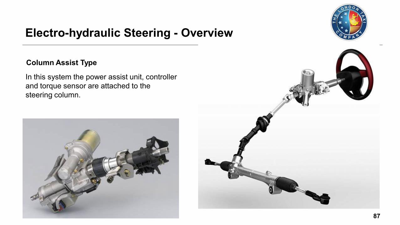
Column Assist Type
Electro-hydraulic Steering - Overview
In this system the power assist unit, controller
and torque sensor are attached to the
steering column.

88
Pinion Assist Type
Electro-hydraulic Steering - Overview
In this system the power assist unit is attached
to the steering gear pinion shaft.
The unit sits outside the vehicle passenger
compartment, allowing assist torque to be
increased greatly without raising interior
compartment noise.

89
Rack Assist Type
Electro-hydraulic Steering - Overview
In this system the power assist unit is
attached to the steering gear rack.
It is located on the rack to allow for greater
flexibility in the layout design.

90
Direct Drive Type
Electro-hydraulic Steering - Overview
In this system the steering gear rack and
power assist unit form a single unit.
The steering system is compact and fits
easily into the engine compartment layout.
The direct assistance to the rack enables
low friction and inertia, which in turn
gives an ideal steering feel.

91
In all of these systems “Active control” as it is
known provides constant feedback from
sensors in the vehicle to the control module,
which calculates sophisticated computer
algorithms.
Sensors such as:
• Fluid Pressure (if electro/hydraulic)
• Fluid Temperature (if electro/hydraulic)
• Steering Angle
• Steering Torque
• Steering Speed
• Engine Speed
• Vehicle Speed
Electro-hydraulic Steering - Overview
Driver
Input
Steering
Column
Torque
Sensor
Steering
Motor
Steering
Angle
Sensor
Vehicle
Speed
Sensor
Traction
Control
Stability
Control
Electronic
Power Steering
Control Module

92
This allows the steering system to react
to the road, the weather and even the
type of driver, and provide assistance
to the front or rear road wheels
independent of direct driver input.
Electro-hydraulic Steering - Overview
Active steering produces enhanced
steering response, stability and handing
improvements to the vehicle without
impacting the base steering feel.

93
Steer By Wire
In recent years vehicle manufacturers have developed
systems such as throttle by wire and brake by wire.
These systems are electronically controlled and the
mechanical elements of these systems have
been removed.
Electro-hydraulic Steering - Future Development
Latest engineering development shows the possibilities
of steer by wire system.
This again will be a massive step forward in vehicle
technology.
With a electronically controlled steering column and
power rack, controlled by a module and a series of
sensors to monitor other systems inputs and driver
activities is something that must not be ignored.

94
During the late 1980’s a number of manufacturers
introduced four-wheel steering in some of their
vehicle range.
4 Wheel Steering Systems - Introduction
Why steer all four wheels?
• At lower speeds, turning the rear wheels in
the opposite direction to the front wheels
results in a smaller turning radius and
faster cornering responses
• At high speeds, turning all four wheels in
concert improves high speed stability
Not all were successful and due to manufacturing
costs, complex designs, many were moth balled.

95
In later years, vehicle manufacturers have utilised
the benefits of modern designed systems which
are controlled by the latest technologies.
4 Wheel Steering Systems - Introduction
A number of different systems are now in
production and all have their own
functional design.
They fall into two categories:
• Active four wheel steering
• Passive rear wheel steering
Whether the manufacturers design uses
twin steering racks, electronic actuators
or specially designed suspension bushings,
both categories can and do improve the
vehicles steering and stability at high and
low speed.

96
In an active four-wheel steering system, all four wheels
turn at the same time when the driver steers.
In most active four wheel steering systems, the rear
wheels are steered by a computer and actuators.
4 Wheel Steering Systems - Active
The rear wheels generally
cannot turn as far
as the front wheels.
Active 4 Wheel Steering

97
4 Wheel Steering Systems - Active
There can be controls to switch off the rear
steer and options to steer only the rear
wheel independent of the front wheels. At low speed (parking) the rear wheels turn
opposite of the front wheels, reducing the
turning radius.
While at higher speeds both front and rear
wheels turn alike (electronically controlled),
so that the vehicle may change position
with less yaw, enhancing straight
line stability.
Active 4 Wheel Steering

98
Many modern vehicles have passive rear steering.
On many vehicles, when cornering, the rear
wheels tend to steer slightly to the outside
of a turn, which can reduce stability.
4 Wheel Steering Systems - Passive
The passive steering system uses the lateral
forces generated in a turn (through suspension
geometry) and the specially designed bushings
to correct this tendency and steer the wheels
slightly to the inside of the corner.
Passive Rear Wheel Steering

99
This improves the stability of the car, through
the turn.
This effect is called compliance under-steer
and it, or its opposite, is present on all
suspensions.
4 Wheel Steering Systems - Passive
On an independent rear suspension system
it is normally achieved by changing the
rates of the rubber bushings in the
suspension.
Some rear suspensions typically have
compliance over-steer due to the
geometry set up.
Passive Rear Wheel Steering