electrical power distribution, 5 installing a downstream ... · to install a downstream...
TRANSCRIPT

© Festo Didactic 38530-20 29
To install a downstream distribution panelboard (DDP) on the Mobile Workstation. To mechanically and electrically connect the DDP to the main distribution panelboard (MDP) installed in the previous job sheets. To wire a branch circuit consisting of a single-phase dual receptacle protected by a conventional circuit breaker. To wire a branch circuit consisting of a single-phase dual receptacle protected by a GFCI circuit breaker. To apply the required identification labels on the MDP and DDP.
1. Perform the basic safety procedures listed in Appendix C of this manual.
2. Carefully examine Part II of the electrical power distribution diagrams provided, to understand the work that has to be done in this job sheet.
3. Identify the three-phase, downstream distribution panelboard (also referred to as a subpanel) to be installed in this job sheet. A typical three-phase, downstream distribution panelboard is shown in Figure 29.
a This type of distribution panelboard is easily recognized by its three busses for the three line conductors (live conductors) and separated neutral and ground busses.
Figure 29. A three-phase, downstream distribution panelboard (subpanel).
Installing a Downstream Distribution Panelboard
Job Sheet 5
OBJECTIVE
PROCEDURE
Busses for line conductors
Neutral bus
Ground busses

Job Sheet 5 – Installing a Downstream Distribution Panelboard
30 © Festo Didactic 38530-20
4. Install the three-phase, downstream distribution panelboard (DDP) on the Mobile Workstation. An additional metal strut is required to fix the DDP to the workstation as shown in Figure 30.
Figure 30. DDP and outlet boxes for the single-phase dual receptacles.
5. Install the two metal outlet boxes for the single-phase dual receptacles on the metal strut located below the MDP. Fasten each metal outlet box with two self-drilling screws.
6. Using the information in Part II of the electrical power distribution riser diagram, identify the conduits or cables required to mechanically interconnect the DDP to the MDP, RCPT2 and RCPT3.
Table 3. Conduits or cables used to interconnect the DDP to the MDP, RCPT2 and RCPT3.
DDP connected to Required conduit or cable
Main distribution panelboard (MDP)
Single-phase dual receptacle (RCPT2)
Single-phase dual receptacle (RCPT3)
Metal outlet box
DDP

Job Sheet 5 – Installing a Downstream Distribution Panelboard
© Festo Didactic 38530-20 31
7. Remove the 1 1/4" knockouts at the two locations shown in Figure 31.
a If required, you can use a knockout reducing washer to reduce the size of a knockout on the MDP or DDP.
Figure 31. DDP mechanically connected to the MDP with conduit and a type-LL conduit body.
8. Cut and ream two pieces of the type of conduit you identified in Table 3 to mechanically connect the DDP to the MPD.
9. Install the two conduits you just cut and the type-LL conduit body required to mechanically connect the DDP to the MDP as shown in Figure 31. Use fittings to connect the conduits to the MDP and DDP. Make sure each fitting is oriented so that the setscrew head is easily accessible. Tighten the setscrews on the conduit body and fittings.
Knockout Type-LL conduit body
Bushing with bonding jumper
Fittings
Knockout
Job Sheet 5 – Installing a Downstream Distribution Panelboard
32 © Festo Didactic 38530-20
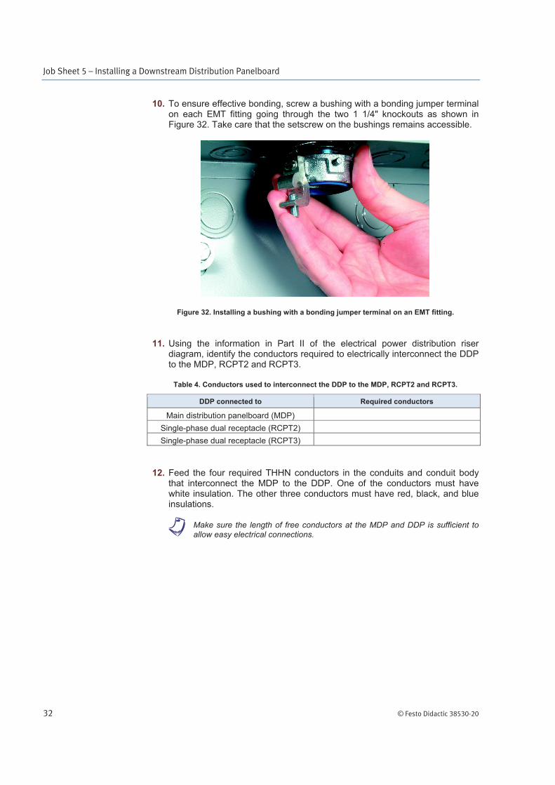
10. To ensure effective bonding, screw a bushing with a bonding jumper terminal on each EMT fitting going through the two 1 1/4" knockouts as shown in Figure 32. Take care that the setscrew on the bushings remains accessible.
Figure 32. Installing a bushing with a bonding jumper terminal on an EMT fitting.
11. Using the information in Part II of the electrical power distribution riser diagram, identify the conductors required to electrically interconnect the DDP to the MDP, RCPT2 and RCPT3.
Table 4. Conductors used to interconnect the DDP to the MDP, RCPT2 and RCPT3.
DDP connected to Required conductors
Main distribution panelboard (MDP)
Single-phase dual receptacle (RCPT2)
Single-phase dual receptacle (RCPT3)
12. Feed the four required THHN conductors in the conduits and conduit body that interconnect the MDP to the DDP. One of the conductors must have white insulation. The other three conductors must have red, black, and blue insulations.
a Make sure the length of free conductors at the MDP and DDP is sufficient to allow easy electrical connections.

Job Sheet 5 – Installing a Downstream Distribution Panelboard
© Festo Didactic 38530-20 33
13. Cut a piece of type MC cable for the connections between the DDP and each metal outlet box. Refer to Figure 33 and make sure the length of free conductor at the DDP and the outlet boxes is in accordance with Article 300.14 of the NEC®.
Figure 33. Type MC cable installed at the metal outlet boxes.
14. Insert an insulating bushing at the ends of each piece of type MC cable.
15. Install a 90° fitting for type MC cable (same fitting as for flexible metal conduit) for the connections to the DDP and the two metal outlet boxes.
16. Remove the required knockouts on the DDP and metal outlet boxes and secure each fitting to the enclosure or box wall using a lock nut.
a Make sure all bends in the two pieces of type MC cable installed are made in accordance with Article 330 in the NEC®.
17. Fasten the two pieces of type MC cable with cable ties as requested in Article 330 of NEC® (see Figure 33).
18. Identify the three-pole circuit breaker required to protect the conductors that feed the DDP. Refer to the electrical power distribution interconnection diagram, Part II, to know the current (ampere) rating of this circuit breaker.
19. Install the circuit breaker in the top-right circuit breaker space of the MDP (beside the circuit breaker installed in the previous job sheet to protect the three-phase receptacle).
Job Sheet 5 – Installing a Downstream Distribution Panelboard
34 © Festo Didactic 38530-20
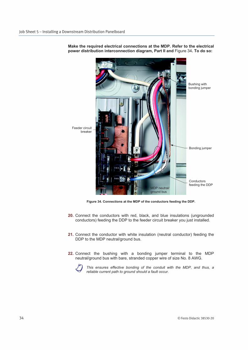
Make the required electrical connections at the MDP. Refer to the electrical power distribution interconnection diagram, Part II and Figure 34. To do so:
Figure 34. Connections at the MDP of the conductors feeding the DDP.
20. Connect the conductors with red, black, and blue insulations (ungrounded conductors) feeding the DDP to the feeder circuit breaker you just installed.
21. Connect the conductor with white insulation (neutral conductor) feeding the DDP to the MDP neutral/ground bus.
22. Connect the bushing with a bonding jumper terminal to the MDP neutral/ground bus with bare, stranded copper wire of size No. 8 AWG.
a This ensures effective bonding of the conduit with the MDP, and thus, a reliable current path to ground should a fault occur.
Conductors feeding the DDP
Bonding jumper
MDP neutral/ ground bus
Bushing with bonding jumper
Feeder circuitbreaker

Job Sheet 5 – Installing a Downstream Distribution Panelboard
© Festo Didactic 38530-20 35
23. Make sure the setscrews on the feeder circuit breaker terminals, MDP neutral/ground bus, and bushing with bonding jumper are well-tightened to ensure solid connections of the conductors.
Make the required electrical connections at the DDP. Refer to the electrical power distribution interconnection diagram, Part II and Figure 35. To do so:
Figure 35. Connections at the DDP of the conductors coming from the MDP.
24. Connect the conductors with red, black, and blue insulations (ungrounded conductors) coming from the MDP to the main terminals of the DDP busses for line (live) conductors.
25. Connect the conductor with white insulation (neutral conductor) coming from the MDP to the main neutral terminal of the DDP neutral bus.
DDP main neutral terminal
DDP mainterminal

Job Sheet 5 – Installing a Downstream Distribution Panelboard
36 © Festo Didactic 38530-20
26. Connect the bushing with a bonding jumper terminal to the DDP ground bus with bare, stranded copper wire of size No. 8 AWG, as shown in Figure 36.
a This ensures effective bonding of the conduit with the DDP, and thus, a reliable current path to ground should a fault occur.
Figure 36. Bushing with a bonding jumper terminal connected to the DDP ground bus.
27. Make sure the setscrews on the DDP terminals, ground bus and bushing with bonding jumper are well-tightened to ensure solid connections of the conductors.
DDP ground bus
Bonding jumper

Job Sheet 5 – Installing a Downstream Distribution Panelboard
© Festo Didactic 38530-20 37
28. Identify the type of single-phase dual receptacle requested in the electrical power distribution interconnection diagram, Part II. Figure 37 shows a single-phase dual receptacle.
Figure 37. A single-phase dual receptacle.
29. Read Article 406 in the NEC® and reference 11 (see Appendix D).
30. Identify the conventional, single-pole circuit breaker required to protect the branch circuit that supplies power to the single-phase dual receptacle labeled RCPT2 in the electrical power distribution interconnection diagram, Part II. Figure 38 shows a conventional, single-pole circuit breaker.
Figure 38. A conventional, single-pole circuit breaker.
31. Read reference 12 (see Appendix D).
32. Install this circuit breaker in the top-right circuit breaker space of the DDP.

Job Sheet 5 – Installing a Downstream Distribution Panelboard
38 © Festo Didactic 38530-20
Make the required electrical connections at the DDP to wire the branch circuit that supplies power to the single-phase dual receptacle labeled RCPT2. To do so:
33. Connect the wire with black insulation from the type MC cable going to the RCPT2 to the terminal of the single-pole, branch circuit breaker installed in the previous step (see Figure 39).
Figure 39. Connections in the DDP of the wires from the type MC cable going to the single-phase dual receptacle (RCPT2).
34. Connect the wire with white insulation from the type MC cable going to the RCPT2 to the DDP neutral bus.
35. Connect the wire with green insulation (equipment grounding conductor) from the type MC cable going to the RCPT2 to the DDP ground bus.
Load live conductor
Load neutral conductor
DDP neutral bus
Conductors going toreceptacle RCPT2
DDP ground bus
Conventional, 1-pole circuit breaker

Job Sheet 5 – Installing a Downstream Distribution Panelboard
© Festo Didactic 38530-20 39
36. Make sure the setscrews on the circuit breaker terminal, neutral and ground busses are well-tightened to ensure solid connections of the conductors.
Make the required electrical connections at the single-phase dual receptacle labeled RCPT2. To do so:
37. Connect the wire with black insulation from the type MC cable to the live (hot) side (brass-colored screws) of the RCPT2 (see Figure 40).
Figure 40. Connections at a single-phase dual receptacle.
38. Connect the wire with white insulation from the type MC cable to the neutral side (silver-colored screws) of the RCPT2.
39. Connect the wire with green insulation (equipment grounding conductor) from the type MC cable to the ground terminal (green screw terminal) of the RCPT2 and the metal outlet box. This requires a splice, made with a #35 solderless connector (wire nut) and two short lengths of No.14 AWG copper wire with green insulation.
Attach the equipment grounding conductor to the metal outlet box using a grounding clip.
40. Make sure the setscrews on all terminals of the RCPT2 are well-tightened to ensure solid connections.
Grounding clip

Job Sheet 5 – Installing a Downstream Distribution Panelboard
40 © Festo Didactic 38530-20
41. Identify the GFCI-type, single-pole circuit breaker required to protect the branch circuit that supplies power to the single-phase dual receptacle labeled RCPT3 in the electrical power distribution interconnection diagram, Part II. Figure 41 shows a GFCI-type, single-pole circuit breaker.
Figure 41. A GFCI-type, single-pole circuit breaker.
42. Read Article 210.8 in the NEC® and references 13 and 14 (see Appendix D).
43. Install this GFCI circuit breaker just below the conventional single-pole circuit breaker installed previously in the DDP.
Job Sheet 5 – Installing a Downstream Distribution Panelboard
© Festo Didactic 38530-20 41
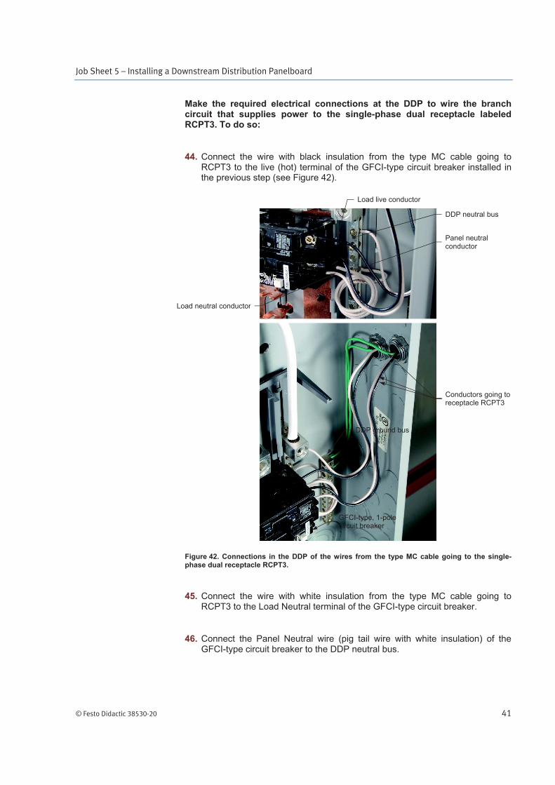
Make the required electrical connections at the DDP to wire the branch circuit that supplies power to the single-phase dual receptacle labeled RCPT3. To do so:
44. Connect the wire with black insulation from the type MC cable going to RCPT3 to the live (hot) terminal of the GFCI-type circuit breaker installed in the previous step (see Figure 42).
Figure 42. Connections in the DDP of the wires from the type MC cable going to the single-phase dual receptacle RCPT3.
45. Connect the wire with white insulation from the type MC cable going to RCPT3 to the Load Neutral terminal of the GFCI-type circuit breaker.
46. Connect the Panel Neutral wire (pig tail wire with white insulation) of the GFCI-type circuit breaker to the DDP neutral bus.
Load neutral conductor
Panel neutral conductor
Load live conductor
GFCI-type, 1-pole circuit breaker
DDP neutral bus
DDP ground bus
Conductors going to receptacle RCPT3

Job Sheet 5 – Installing a Downstream Distribution Panelboard
42 © Festo Didactic 38530-20
47. Connect the wire with green insulation (equipment grounding conductor) from the type MC cable going to RCPT3 to the DDP ground bus.
48. Make sure the setscrews on the GFCI-type circuit breaker, load neutral terminal, and neutral bus are well-tightened to ensure solid connections of the conductors.
Make the required electrical connections at the single-phase dual receptacle RCPT3. To do so:
49. Connect the wire with black insulation from the type MC cable to the live (hot) side (brass-colored screws) of the RCPT3 (see Figure 40).
50. Connect the wire with white insulation from the type MC cable to the neutral side (silver-colored screws) of the RCPT3.
51. Connect the wire with green insulation (equipment grounding conductor) from the type MC cable to the ground terminal (green screw terminal) of the RCPT3 and the metal outlet box.
This requires a splice, made with a #35 solderless connector (wire nut) and two short lengths of No.14 AWG copper wire with green insulation. Attach the equipment grounding conductor to the metal outlet box using a grounding clip.
52. Make sure the setscrews on all terminals of the RCPT3 are well-tightened to ensure solid connections.

Job Sheet 5 – Installing a Downstream Distribution Panelboard
© Festo Didactic 38530-20 43
Install the MDP front panel and apply the identification label required for the circuit breaker protecting the DDP feeder. To do so:
53. Make an opening at the proper location in the MDP front panel for the three-pole, feeder circuit breaker installed in the MDP (see Figure 43).
Figure 43. MDP with the front panel installed and labels applied.
54. Fasten the front panel to the MDP with the provided screws.
55. Apply a label marked as indicated in the electrical power distribution interconnection diagram, Part II, on the MDP front panel to identify the feeder circuit breaker installed in this job sheet. This label should be located just beside the feeder branch circuit breaker (see Figure 43).

Job Sheet 5 – Installing a Downstream Distribution Panelboard
44 © Festo Didactic 38530-20
Install the DDP front panel and apply the identification labels required as shown in Figure 44. To do so:
Figure 44. DDP with the front panel installed and labels applied.
56. Make an opening at the proper location in the DDP front panel for the two single-pole circuit breakers installed in the DDP.
57. Fasten the front panel to the DDP with the provided screws.
58. Apply labels marked as indicated in the electrical power distribution interconnection diagram, Part II, on the DDP front panel to identify the two circuit breakers installed in the DDP during this job sheet. These labels should be located just beside the circuit breakers.
59. Apply a label marked "DDP" at the top of the DDP front panel.
60. Install a faceplate on each of the single-phase dual receptacles.
61. Ask your instructor to check and approve your work.
62. Disassemble the equipment set up following the directions of your instructor.
Name: ______________________________ Date: ___________________
Instructor's approval: ______________________________________________