electrical machines (e&i) -...
TRANSCRIPT

1
ELECTRICAL MACHINES

2
EI2201 ELECTRICAL MACHINES L T P C
(Common to EIE & ICE) 3 1 0 4
AIM To impart basic knowledge on Electrical machines, principles and its behavior.
OBJECTIVES
At the end of this course, student would have been exposed to: 1.Theory of structures, operating principle, characteristics, and applications of D.C and A.C rotating machines and transformers in detail. 2. Introductory knowledge on Special Machines.
UNIT I D.C. MACHINES 12 Construction of D.C. Machines - Principle and theory of operation of D.C. generator - EMF equation - Characteristics of D.C. generators - Armature reaction – Commutation - Principle of operation of D.C. motor - Voltage equation - Torque equation - Types of D.C. motors and their characteristics –Starters - Speed control of D.C. motors - Applications. UNIT II TRANSFORMERS 9
Principle - Theory of ideal transformer - EMF equation - Construction details of shell and core type transformers - Tests on transformers - Equivalent circuit - Phasor diagram - Regulation and efficiency of a transformer - Introduction to three - phase transformer connections. UNIT III SYNCHRONOUS MACHINES 8 Principle of alternators:- Construction details, Equation of induced EMF and Vector diagram -Synchronous motor:- Starting methods, Torque, V curves, Speed control and Hunting. UNIT IV INDUCTION MACHINES 9 Induction motor:- Construction and principle of operation, Classification of induction motor, Torque equation, Condition for maximum torque, Equivalent Circuit, Starting methods and Speed control of induction motors. UNIT V SPECIAL MACHINES 7
Types of single phase motor –Double revolving field theory – Cross field theory – Capacitor start capacitor run motors – Shaded pole motor – Repulsion type motor – Universal motor – Hysteresis motor - Permanent magnet synchronous motor – Switched reluctance motor – Brushless D.C motor. L = 45 TOTAL: 45 PERIODS
TEXT BOOKS: 1. Nagrath, I.J., and Kothari, D.P., “ Electrical Machines”, Tata McGraw - Hill, 1997. 2. Fitzgerald A.E, Kingsley C., Umans, S. and Umans S.D., “Electric Machinery”, McGraw- Hill, Singapore, 2000. REFERENCES: 1. Theraja, B.L., “A Text book of Electrical Technology”, Vol.II, S.C Chand and Co., New Delhi, 2007. 2. Del Toro, V., “Electrical Engineering Fundamentals”, Prentice Hall of India, New Delhi, 1995. 3. Cotton, H., “Advanced Electrical Technology”, Sir Isaac Pitman and Sons Ltd., London, 1999.

3
TABLE OF CONTENTS
Chapter 1 Alternators
1.1 Construction of DC Machine 6
1.2 Principle and theory of DC Generator 8
1.3 E.M.F Equation of DC Generator 9
1.4 Power Flow in DC Generator 10
1.5 Types of DC Generators 10
1.6 Methods of Armature Reaction 13
1.7 Methods of Improving Commutation-E.M.F. Commutation 14
1.8 Generator types & Characteristics 15
1.9 DC Motor 21
1.10 Starting of D.C shunt motor 25
1.11 Speed control of shunt motor 31
1.12 Series motor 34
1.13 Applications of DC motor 37
Chapter 2 TRANSFORMERS
2.1 Introduction 40
2.2. Basics of Transformer 40
2.3 Transformer Construction 42
2.4 Equivalent Circuit of Transformer 43
2.5 Phasor Diagram and Voltage Regulation 48
2.6 Voltage Regulation 50
2.7 Losses and Efficiency of Transformer 51
2.8 Transformers in Three Phase Systems 65
Chapter 3 SYNCHRONOUS MACHINES
3.1 Introduction 60
3.2 Concept of slip rings and brush assembly 60
3.3 Construction of synchronous generator(stator and rotor) 62
3.4 Working principle of synchronous generator 65
3.5 E.m.f. Equation of an alternator 68

4
3.6 Armature reaction 77
3.7 Concepts of synchronous reactance and impedance 79
3.8 voltage regulation of an alternator 79
3.9 Blondel's two reaction theory 94
3.10 Direct and quadrature axis synchronous reactance 96
3.11 Details analysis of phasor diagram for synchronous gen 97
3.12 Determination of xd and xq using slip test 99
3.13 Introduction to synchronization of alternators 101
3.14 Phasor diagram 112
3.15 Synchronous Motor 118
3.16. Types 118
3.17 Construction of three phase synchronous motor 118
3.18 Principle of working of 3-phase synchronous motor 119
3.19 Methods of starting synchronous motor 121
3.20 Behaviour of synchronous motor on loading 123
3.21 Analysis of phasor diagram 127
3.22 V-Curves and inverted v-curves 130
3.23 Expression for back e.m.f or induced e.m.f. Per phase in s.m. 132
3.24 Power flow in synchronous motor 134
3.25 Salient pole synchronous motor 138
3.26 Hunting in synchronous motor 139
3.27 Synchronization with infinite bus bar 140
3.28 Synchronous condensers 141
3.29 Applications of three phase synchronous motor 143
3.30 Comparison of synchronous and induction motor 143
3.31 Synchronous induction motor 144
Chapter 4 INDUCTION MACHINES
4.1 Introduction 152
4.2 Rotating Magnetic field 152
4.3 Construction of Three phase induction motor 153
4.4 Working principle 155
4.5 Slip of the induction motor 156

5
4.6 Torque Equation 156
4.7 Relationship between P2r, Pc, Pm 157
4.8 Need of Starter 158
4.9 Torque-slip characteristic 159
4.10 Losses in induction motor 160
4.11 Power flow in an induction motor 161
4.12 Necessity of Starter 161
4.13 Types of Starter 162
4.14 Speed Control of Three Phase Induction Motor 169
Chapter 5 SPECIAL MACHINES
5.1 Introduction 186
5.2 Types of Single Phase AC Motors 186
5.3 Construction of Single Phase Induction motor 186
5.4 Working Principle and Operation of Single phase Induction motor 187
5.5 Cross field Theory 188
5.6 Starting of Single Phase induction Motor 188
5.7 Shaded Pole Motor 192
5.8 Universal Motor 192
5.9 Repulsion Motor 194
5.10 Brush Less DC Motor 195
5.11 Permanent Magnet Synchronous Motor 197
5.12 Reluctance Motor 197
5.13 Hysteresis Motor 198

6
UNIT I D.C. MACHINES
UNIT I D.C. MACHINES 12 Construction of D.C. Machines - Principle and theory of operation of D.C. generator - EMF equation - Characteristics of D.C. generators - Armature reaction – Commutation - Principle of operation of D.C. motor - Voltage equation - Torque equation - Types of D.C. motors and their characteristics –Starters - Speed control of D.C. motors - Applications. 1.1 Construction of DC Machine:
Figure 1.1.Cross section of DC Machine The DC Generator has the following important parts: (a) Yoke (b) Pole of Generator (c) Field Winding (d) Armature of DC Generator (e) Commutator (f) Brushes and Bearing (a) Yoke : The ring shaped body of the DC machine frame which makes the magnetic path for the magnetic fluxes from the main poles and inter poles is called Yoke. it serves two purposes for an DC machines,
(i) It provides mechanical support to the magnetic pole shoes and protecting cover of a machine. (ii) It carries and acting as the path for the magnetic field flux produced by field windings.
In small Rating DC generator, yoke are made of cast iron. In the case of large Machines ,where weight of the machine also in concern, cast steel or rolled steel is used. The nature of Cast iron(0.8 Wb/sq.m) is cheaper in cost but heavier than Cast steel(1.5 Wb/sq.m). Yokes are formed in the form of Cylindrical shape with the help rectangular sheet and the edges are welded together at the bottom. (b) Pole of Generator :The poles or Pole shoes are fabricated steel and it is welded to the frame by means of bolts. Pole shoes are generally laminated to reduce the Eddy current Losses in DC Machine. The thickness of the lamination is in the range of 0.04″ to 0.01″. The pole shoes are shaped as shown in the diagram to get air gap at the tips. Inter-poles are smaller in size and additional poles located in between the main poles. It is also laminated and connected with yoke through bolts. The inter poles are also called as commutating poles to improve Commutation and Improves the efficiency of a DC machine by reducing Armature reaction.

7
(c)Field Winding: The field winding made in the form of a concentric coil wound around the main poles. It is wounded to carry the excitation current and produce the main field flux in the machine. Thus the poles are energized by separate supply or on its own output. There are two types of windings are generally employed in a DC generator are ,(i) shunt winding, large number of turns of small thickness of copper conductors used. The resistance of shunt winding always larger than the armature winding resistance. (ii) series winding, a few turns of heavy cross section conductor is used. The resistance of series windings is low and is comparable to armature resistance. Some machines may have both the windings on the poles with their fluxes opposing or aiding each other. (d)Armature Winding: The armature coils are wounded on the surface of slotted armature .To avoid the conductors flying outside during armature rotation ,the armature windings are formed and covered with tape and fixed into the open slots on the armature. In a small machines, the winding can be done through hands .In the case of large machines slot segments are used to prevent the coils flying outside during rotation . The end portion of the windings are short circuited with commutator end. The armature design should be done to balance and reduce the centrifugal forces at the high operating speeds. Compensating winding windings are required to reduce the effect of Armature reaction and it is presented only in large rating machines. (e) Commutator: Commutator is very important element in DC machines, which made of copper segments together with mica/micanite insulating material to separate each segment.The diagram of Commutator is as shown in figure 1.2. The commutator is an rigid and solid assembly of insulated copper strips and can rotate at high speeds. Each segment of Commutator is provided with a ’riser’ in which the ends of the armature coils get connected. The surface of the commutator is Concentric and Smooth one to collect current form it with the help of brushes.
Figure 1.2.Commutator of DC Machine
(f) Brush, brush holders and Bearings: A brush is an device which conducts current between stationary wires and moving parts, most commonly in a rotating shaft. Brushes are fixed above the surface of commutator to collect current from its segments. Mainly graphite and Carbon materials are used as brush material. The type of the brush selection depends on the peripheral speed of the commutator and the working voltage.

8
Figure 1.3.Brushes of a DC Machine
The brushes are designed to press on the commutator with the help of tension springs. This is to provide proper contact between the brushes and the commutator during high speeds of operation. Brushes jumping over the segments provides poor armature current collection and it is prevented the brushes are made up of graphite (with added copper). In a Small machines ball bearings are employed at both ends. For larger machines well designed roller bearings are used at the driving end. The bearings are housed inside prevent moisture and dust entering it .The bearing must always be lubricated properly for smooth operation and long life of generator. 1.2 Principle and theory of DC Generator
In 1831, Michael Faraday, gave two laws of electromagnetism called Faraday’s law of electro magnetic induction. This law explains the working principle of DC generators. It explains the relationship between electric circuit and magnetic field.. According to faraday’s first law, there is any change in magnetic field of a coil, the Emf is induced in the coil. This is called induced Emf .When the coil or circuit is closed, the current will flow through the circuit it is named as induced current. According to Faraday’s Second Law, the magnitude of induced in a coil is directly proportional to the amount of rate of change of flux linkages with the coil. Consider a magnet moving above the surface a coil and assume two instants at time t1 and time t2. Flux linkage with the coil at time, t1 = NΦ1 Wb Flux linkage with the coil at time, t2 = NΦ2 wb Resultant or change in flux = NΦ where Φ = Φ2 – Φ1 The rate of change of flux linkage or Induced Emf e = NΦ / t The rate of change of flux linkage E= NdΦ/dt…………………….1.1 According to lenz law, E= -NdΦ/dt…………………1.2 The direction of the current and magnetic field is determined by Fleming Right Hand Rule. The principle of DC generator explained through Single Loop or winding placed in a magnetic field .
Figure 1.4.Single Loop DC Generator
In the figure 1.4 the single winding with rectangular shape is placed between two different poles of a magnet. Let’s us consider, the single conductor is in the position ABCD without any rotation there is no induced enf in it ,because no rate of change of flux will occur. The same conductor starts rotating inside the constant magnetic field with its axis ,it cuts the magnetic field .Due to this the emf is induced in the conductor .The loop is opened and connect it with a split rings and brushes as shown in the figure 1.5 . Split ring are helping

9
brushes to take current outside to supply the external load terminals are connected with two carbon brushes . Working principle of dc generator
Figure 1.5.Single Loop DC Generator with load
In the first half of the revolution ,it is seen that the current flows through the direction ABLMCD i.e. brush X in contact with segment a. In the next half revolution, the direction of the induced current in the coil is reversed ,But the position of the segments a and b are also reversed so it results that brush X comes in touch with that segment b. Hence, the current in the load resistance again flows follows the same path. The output wave form of the current through the load circuit is is purely sinusoidal and the current is unidirectional. 1.3 E.M.F Equation of DC Generator:
Let Φ = flux/pole in weber Z = total number of armture conductors = No.of slots x No.of conductors/slot P = No.of generator poles A = No.of parallel paths in armature N = armature rotation in revolutions per minute (r.p.m) E = e.m.f induced in any parallel path in armature Generated e.m.f Eg = e.m.f generated in any one of the parallel paths i.e E. Average e.m.f generated /conductor = dΦ/dt volt (n=1) flux cut/conductor in one revolution dΦ = ΦP Wb No.of revolutions/second = N/60 Time for one revolution, dt = 60/N second Hence, according to Faraday's Laws of Electroagnetic Induction, E.M.F generated /conductor is
dΦ/dt =ΦPN/60…………………………..1.3 therefore ,the generated emf of DC generator with’ Z ‘no of conductors and ‘A’ parallel path is Eg= ΦPNZ/60A volts……………………………1.4 For a simplex wave-wound generator,
No.of parallel paths A = 2 No.of conductors (in series) in one path = Z/2 E.M.F. generated/path is Eg= ΦPNZ/60*2= ΦPNZ/120………………………………1.5

10
For a simplex lap-wound generator
No.of parallel paths A = P No.of conductors (in series) in one path = Z/P E.M.F.generated/path Eg= ΦPNZ/60*P= Eg= ΦNZ/60
………………………………1.6
1.4 Power Flow in DC Generator: The Power flow in the DC generator is explained in the diagram
Figure 1.6.Power flow diagram of DC Generator From the diagram we understand that, the mechanical power input of DC generator is converted in to Electrical power as a Output . The total input energy should not be converted as Electrical power output, because different types of Losses are presented in it. 1.5 Types of DC Generators
“Energy can be converted from one form to other form” – A generator does the same – it converts mechanical energy to electrical energy. Mechanical energy can be created by using water turbines, steam turbines, internal combustion engines etc. And a generator converts this mechanical energy to electrical energy. Generators can be broadly classified as AC generators and DC generators. Here lets take a look the the types of DC generators. DC generators are classified based on their method of excitation. So on this basis there are two types of DC generators:- 1. Separately excited DC generator 2. Self excited DC generator Self excited DC generator can again be classified as 1) DC Series generator 2) DC Shunt
generator and 3) DC Compound generator. Let’s take a brief look at how all these differ. 1.5.1 Separately excited DC generator
As you can guess from the name itself , this dc generator has a field magnet winding which is excited using a separate voltage source (like battery). You can see the representation

11
in the below image. The output voltage depends on the speed of rotation of armature and field current. The higher the speed of rotation and current – the higher the output e.m.f
Figure 1.7 Separately excited DC generator
Note: Separately excited DC generators are rarely used in practice.
1.5.2. Self Excited DC Generator
These are generators in which the field winding is excited by the output of the generator itself. As described before – there are three types of self excited dc generators – they are 1)
Series 2) Shunt and 3) Compound. A series DC generator is shown below in fig 1.8 in which the armature winding is connected in series with the field winding so that the field current flows through the load as well as the field winding.Field winding is a low resistance,thick wire of few turns. Series generators are also rarely used
Figure 1.8 Self excited DC Series generator
A shunt DC generator is shown in figure 1.9, in which the field winding is wired parallel to armature winding so that the voltage across both are same. The field winding has high

12
resistance and more number of turns so that only a part of armature current passes through field winding and the rest passes through load.
Figure 1.9 Self excited DC Shunt generator
A compound generator is shown in figure below. It has two field findings namely Rsh and Rse. They are basically shunt winding (Rsh) and series winding (Rse). Compound generator is of two types – 1) Short shunt and 2) Long shunt
Figure 1.10 Self excited DC Compound generator
Short shunt:- Here the shunt field winding is wired parallel to armature and series field winding is connected in series to the load. It is shown in fig (1)
Long shunt:- Here the shunt field winding is parallel to both armature and series field winding (Rse is wired in series to the armature). It is shown in figure (2)

13
So you have got a basic idea about the types of DC generators! Now you may know that these generators are used only for special industrial purposes where there is huge demand for DC production. Otherwise electrical energy is produced by AC generators and is transmitted from one place to other as AC itself. When a DC power is required, we usually convert AC to DC using rectifiers. 1.6 Methods of Armature Reaction
In a d.c. generator, the purpose of field winding is to produce magnetic field (called main flux) whereas the purpose of armature winding is to carry armature current. Although the armature winding is not provided for the purpose of producing a magnetic field, nevertheless the current in the armature winding will also produce magnetic flux (called armature flux). The armature flux distorts and weakens the main flux posing problems for the proper operation of the d.c. generator. The action of armature flux on the main flux is called armature reaction.
It was hinted that current in the coil is reversed as the coil passes a brush. This phenomenon is termed as commutation. The criterion for good commutation is that it should be sparkless. In order to have sparkless commutation, the brushes should lie along magnetic neutral axis .So far we have assumed that the only flux acting in a d.c. machine is that due to the main poles called main flux. However, current flowing through armature conductors also creates a magnetic flux (called armature flux) that distorts and weakens the flux coming from the poles. This distortion and field weakening takes place in both generators and motors. The action of armature flux on the main flux is known as armature reaction. The phenomenon of armature reaction in a d.c. generator is shown in Fig. (1.11). Only one pole is shown for clarity. When the generator is on no-load, a smal1 current flowing in the armature does not appreciably affect the main flux Φ1 coming from the pole [See Fig 1.11 (i)]. When the generator is loaded, the current flowing through armature conductors sets up flux Φ1. Fig. (1.11 ) (ii) shows flux due to armature current alone. By superimposing Φ1 and Φ2, we obtain the resulting flux Φ3 as shown in Fig. (1.11 ) (iii). Referring to Fig (1.11 ) (iii), it is clear that flux density at; the trailing pole tip (point B) is increased while at the leading pole tip (point A) it is decreased. This unequal field distribution produces the following two effects: (i)The main flux is distorted.(ii) Due to higher flux density at pole tip B, saturation sets in. Consequently, the increase in flux at pole tip B is less than the decrease in flux under pole tip A. Flux Φ3 at full load is, therefore, less than flux Φ1 at no load. As we shall see, the weakening of flux due to armature reaction depends upon the position of brushes.
Figure 1.11 armature reactions in a DC generator

14
1.6.1Geometrical and Magnetic Neutral Axes (i) The geometrical neutral axis (G.N.A.) is the axis that bisects the angle between the centre line of adjacent poles [See Fig. 1.12 (i)]. Clearly, it is the axis of symmetry between two adjacent poles.
Figure 1.12 geometrical neutral axis and magnetic neutral axis of DC generator
(ii) The magnetic neutral axis (M. N. A.) is the axis drawn perpendicular to the mean direction of the flux passing through the centre of the armature. Clearly, no e.m.f. is produced in the armature conductors along this axis because then they cut no flux. With no current in the armature conductors, the M.N.A. coincides with G, N. A. as shown in Fig. [1.12(ii)]. In order to achieve spark less commutation, the brushes must lie along M.N.A. 1.7 Methods of Improving Commutation-E.M.F. Commutation
In this method, an arrangement is made to neutralize the reactance voltage by producing a reversing voltage in the coil undergoing commutation. The reversing voltage acts in opposition to the reactance voltage and neutralizes it to some extent. If the reversing voltage is equal to the reactance voltage, the effect of the latter is completely wiped out and we get sparkless commutation. The reversing voltage may be produced in the following two ways: (i) By brush shifting (ii) By using interpoles or compoles 1.7.1 By Brush Shifting
In this method, the brushes are given sufficient forward lead (for a generator) to bring the short-circuited coil (i.e., coil undergoing commutation) under the influence of the next pole of opposite polarity. Since the short-circuited coil is now in the reversing field, the reversing voltage produced cancels the reactance voltage. This method suffers from the following drawbacks:(a) The reactance voltage depends upon armature current. Therefore, the brush shift will depend on the magnitude of armature current which keeps on changing. This necessitates frequent shifting of brushes. (b) The greater the armature current, the greater must be the forward lead for a generator. This increases the demagnetizing effect of armature reaction and further weakens the main field.
1.7.2 By Using Inter poles or Com poles The best method of neutralizing reactance voltage is by, using interpoles or compoles.
The best way to produce reversing voltage to neutralize the reactance voltage is by using interpoles or compoles. These are small poles fixed to the yoke and spaced mid-way between the main poles (See Fig. 1.13).
They are wound with comparatively few turns and connected in series with the armature so that they carry armature current. Their polarity is the same as the next main pole ahead in the direction of rotation for a generator (See Fig. 1.13). Connections for a d.c. generator with interpoles is shown in Fig. (1.13).

15
Figure 1.13 Inter poles and its connections in a DC generator
1.7.3 Functions of Interpoles The machines fitted with inter poles have their brushes set on geometrical neutral axis
(no lead). The inter poles perform the following two functions:
(i) As their polarity is the same as the main pole ahead (for a generator), they induce an e.m.f. in the coil (undergoing commutation) which opposes reactance voltage. This leads to sparkless commutation. The e.m.f. induced by compoles is known as commutating or reversing e.m.f. Since the interpoles carry the armature current and the reactance voltage is also proportional to armature current, the neutralization of reactance voltage is automatic. (ii) The m.m.f. of the compoles neutralizes the cross-magnetizing effect of armature reaction in small region in the space between the main poles. It is because the two m.m.f.s oppose each other in this region. Fig. 1.14 shows the circuit diagram of a shunt generator with commutating winding and compensating winding. Both these windings are connected in series with the armature and so they carry the armature current. However, the functions they perform must be understood clearly. The main function of commutating winding is to produce reversing (or commutating) e.m.f. in order to cancel the reactance voltage. In addition to this, the m.m.f. of the commutating winding neutralizes the cross magnetizing ampere-turns in the space between the main poles. The compensating winding neutralizes the cross-magnetizing effect of armature reaction under the pole faces.
Figure 1.14 shunt generator with commutating winding
1.8 Generator types & Characteristics D.C generators may be classified as (i) separately excited generator, (ii) shunt
generator, and (iii) series generator and (iv) compound generator.

16
In a separately excited generator field winding is energised from a separate voltage source in order to produce flux in the machine. So long the machine operates in unsaturated condition the flux produced will be proportional to the field current. In order to implement shunt connection, the field winding is connected in parallel with the armature. It will be shown that subject to fulfillment of certain conditions, the machine may have sufficient field current developed on its own by virtue of its shunt connection. In series d.c machine, there is one field winding wound over the main poles with fewer turns and large cross sectional area. Series winding is meant to be connected in series with the armature and naturally to be designed for rated armature current. Obviously there will be practically no voltage or very small voltage due to residual field under no load condition (I
a =
0). However, field gets strengthened as load will develop rated voltage across the armature with reverse polarity, is connected and terminal voltage increases. Variation in load resistance causes the terminal voltage to vary. Terminal voltage will start falling, when saturation sets in and armature reaction effect becomes pronounced at large load current. Hence, series generators are not used for delivering power at constant voltage. Series generator found application in boosting up voltage in d.c transmission system. A compound generator has two separate field coils wound over the field poles. The coil having large number of turns and thinner cross sectional area is called the shunt field coil and the other coil having few number of turns and large cross sectional area is called the series field coil. Series coil is generally connected in series with the armature while the shunt field coil is connected in parallel with the armature. If series coil is left alone without any connection, then it becomes a shunt machine with the other coil connected in parallel. Placement of field coils for shunt, series and compound generators are shown in figure 1.15. Will develop rated voltage across the armature with reverse polarity.
Figure 1.15 field coils for shunt, series and compound generators
1.8.1 Characteristics of a separately excited generator No load or Open circuit characteristic
In this type of generator field winding is excited from a separate source, hence field current is independent of armature terminal voltage as shown on figure 1.16. The generator is driven by a prime mover at rated speed, say n rps. With switch S in opened condition, field is excited via a potential divider connection from a separate d.c source and field current is gradually increased. The field current will establish the flux per pole Φ. The voltmeter V connected across the armature terminals of the machine will record the generated emf (E
G =
pnΦz/a=knΦ). Remember pz/a is a constant (k) of the machine. As field current is increased, E
G will increase. E
G versus I
f plot at constant speed n is shown in figure (38.3a).

17
Figure 1.16 Schematic diagram of separately excited DC generator
It may be noted that even when there is no field current, a small voltage (OD) is generated due to residual flux. If field current is increased, Φ increases linearly initially and O.C.C follows a straight line. However, when saturation sets in, φ practically becomes constant and hence E
g too becomes constant. In other words, O.C.C follows the B-H characteristic, hence
this characteristic is sometimes also called the magnetisation characteristic of the machine. It is important to note that if O.C.C is known at a certain speed n
l, O.C.C at another speed n
2
can easily be predicted. It is because for a constant field current, ratio of the generated voltages becomes the ratio of the speeds as shown below and the characteristics of No load or Open circuit characteristic and Load characterisitcs as shown in the figure 1.17
Figure 1.17 O.C.C and Load characteristics of separately excited DC generator
Therefore points on O.C.C at n
2 can be obtained by multiplying ordinates of O.C.C at n
1 with
the ratio n2/n1 O.C.C at two different speeds are shown in the following figure 1.18

18
Figure 1.18 O.C.C characteristics with different speed values of separately excited DC
generator
Load characteristic of separately excited generator Load characteristic essentially describes how the terminal voltage of the armature of a
generator changes for varying armature current Ia. First at rated speed, rated voltage is generated across the armature terminals with no load resistance connected across it (i.e., with S opened) by adjusting the field current. So for Ia
= 0, V = Eo
o should be the first point on the
load characteristic. Now with S is closed and by decreasing RL
from infinitely large value, we
can increase Iaa
gradually and note the voltmeter reading. Voltmeter reads the terminal
voltage and is expected to decrease due to various drops such as armature resistance drop and brush voltage drop. In an uncompensated generator, armature reaction effect causes additional voltage drop. While noting down the readings of the ammeter A2 and the voltmeter V, one must see that the speed remains constant at rated value. Hence the load characteristic will be drooping in nature as shown in figure 1.17. 1.8.2 Characteristics of a shunt generator We have seen in the previous section that one needs a separate d.c supply to generate d.c voltage. Is it possible to generate d.c voltage without using another d.c source? The answer is yes and for obvious reason such a generator is called self excited generator. Field coil (F1, F2) along with a series external resistance is connected in parallel with the armature terminals (A1, A2) of the machine as shown in figure (1.19). Let us first qualitatively explain how such connection can produce sufficient voltage. Suppose there exists some residual field. Therefore, if the generator is driven at rated speed, we should expect a small voltage (knΦres ) to be induced across the armature. But this small voltage will be directly applied across the field circuit since it is connected in parallel with the armature. Hence a small field current flows producing additional flux. If it so happens that this additional flux aids the already existing residual flux, total flux now becomes more generating more voltage. This more voltage will drive more field current generating more voltage. Both field current and armature generated voltage grow cumulatively. This growth of voltage and the final value to which it will settle down can be understood by referring to figure 1.20. where two plots have been shown. One corresponds to the O.C.C at rated speed and obtained by connecting the generator in separately excited fashion as detailed in the preceding section. The other one is the V-I characteristic of the field circuit which is a straight line passing through origin and its slope represents the total field circuit resistance.

19
Figure 1.19 Schematic diagram of DC Shunt generator
Figure 1.20 O.C.C characteristics DC shunt generator
Initially voltage induced due to residual flux is obtained from O.C.C and given by Od. The field current thus produced can be obtained from field circuit resistance line and given by Op. In this way voltage build up process continues along the stair case. The final stable operating point (M) will be the point of intersection between the O.C.C and the field resistance line. If field circuit resistance is increased, final voltage decreases as point of intersection shifts toward left. The field circuit resistance line which is tangential to the O.C.C is called the critical field resistance. If the field circuit resistance is more than the critical value, the machine will fail to excite and no voltage will be induced. Suppose a shunt generator has built up voltage at a certain speed. If the speed of the prime mover is reduced without changing R
f, the developed voltage will be less as because the O.C.C at lower speed will
come down If speed is further reduced to a certain critical speed (ncrir), the present field
resistance line will become tangential to the O.C.C at ncr For any speed below ncr, no voltage built up is possible in a shunt generator. A shunt generator driven by a prime mover, can not built up voltage if it fails to comply any of the conditions listed below.
1. The machine must have some residual field. To ensure this one can at the beginning excite the field separately with some constant current. Now removal of this current will leave some amount of residual field.
2. Field winding connection should be such that the residual flux is strengthened by the
field current in the coil. If due to this, no voltage is being built up, reverse the field terminal connection.
3. Total field circuit resistance must be less than the critical field resistance.

20
Load characteristic of shunt generator With switch S in open condition, the generator is practically under no load condition as field current is pretty small. In other words, Eo
o and Ia
a = 0 is the first point in the load
characteristic. To load the machine S is closed and the load resistances decreased so that it delivers load current IL .The drop in the terminal voltage will be caused by the usual Iaradrop, brush voltage drop and armature reaction effect. Apart from these, in shunt generator, as terminal voltage decreases, field current hence excited motor, here IL
≠ IaIn fact, for shunt
generator, Iaa
= IL - I
ff So increase of I
L will mean increase of Ia
a Remember in shunt
generator, field current is decided by the terminal voltage by virtue of its parallel connection with the armature. Figure 1.21 shows the plot of terminal voltage versus armature current which is called the load characteristic.
Figure 1.21 O.C.C and Load characteristics DC shunt generator
1.8.3 Compound generator As introduced earlier, compound machines have both series and shunt field coils. On
each pole these two coils are placed as shown in figure 38.1. Series field coil has low resistance, fewer numbers of turns with large cross sectional area and connected either in series with the armature or in series with the line. On the other hand shunt field coil has large number of turns, higher resistance, small cross sectional area and either connected in parallel across the armature or connected in parallel across the series combination of the armature and the series field. Depending on how the field coils are connected, compound motors are classified as short shunt and long shunt types as shown in figures 1.22(a) and (b)
Figure 1.22.(a)Short shunt Compound generator

21
Figure 1.22.(b)Long shunt Compound generator
Series field coil may be connected in such a way that the mmf produced by it aids the shunt field mmf-then the machine is said to be cumulative compound machine, otherwise if the series field mmf acts in opposition with the shunt field mmf – then the machine is said to be differential compound machine. In a compound generator, series field coil current is load dependent. Therefore, for a cumulatively compound generator, with the increase of load, flux per pole increases. This in turn increases the generated emf and terminal voltage. Unlike a shunt motor, depending on the strength of the series field mmf, terminal voltage at full load current may be same or more than the no load voltage. When the terminal voltage at rated current is same that at no load condition, then it is called a level compound generator. If however, terminal voltage at rated current is more than the voltage at no load, it is called a over compound generator. The load characteristic of a cumulative compound generator will naturally be above the load characteristic of a shunt generator as depicted in figure 1.23. At load current higher than the rated current, terminal voltage starts decreasing due to saturation, armature reaction effect and more drop in armature and series field resistances.
Figure 1.23Load characteristics of DC generators
To understand the usefulness of the series coil in a compound machine let us undertake the following simple calculations. Suppose as a shunt generator (series coil not connected) 300 AT/pole is necessary to get no load terminal voltage of 220 V. Let the terminal voltage becomes 210 V at rated armature current of 20 A. To restore the terminal voltage to 220 V, shunt excitation needs to be raised such that AT/pole required is 380 at 20 A of rated current. As a level compound generator, the extra AT (380-300 = 80) will be provided by series field. Therefore, number of series turns per pole will be 80/20 = 4. Thus in a compound generator series field will automatically provide the extra AT to arrest the drop in terminal voltage which otherwise is inevitable for a shunt generator. For the differentially compounded generator where series field mmf opposes the shunt field mmf the terminal voltage decreases fast with the increase in the load current. 1.9 DC Motor
DC motor converts electrical energy into mechanical energy. When a current carrying conductor is placed in a magnetic field, a force acts on the conductor and conductor moves in the direction of force. When the DC machine is connected to DC supply a current passes through the armature winding.

22
Figure 1.24 DC Motor Construction The construction of DC motor is as shown in the figure 1.24. When conductors of armature winding carry outward current under north and incoming current under south pole then those conductors experience a force in clockwise direction according to fleming’s left hand rule. Due to this force, conductors move in clockwise direction. The direction of current is reversed by commutator, which causes the moving conductor coming under different pole to carry reverse current. This causes the force on the conductor to be again in the same direction as flux and current both change direction simultaneously. Thus armature conductors always experience force in same direction. 1.9.1 Back EMF When the armature of a DC motor rotates, an emf is induced in armature conductors known as back emf which opposes the applied voltage.
If Ra is armature resistance then V =Eb +Ia Ra .
where Ia is armature current and V is applied voltage
Back emf makes a dc motor self-regulating. When speed is low then back emf will less and armature current will be large. 1.9.2 Speed Regulation The back emf in armature is
since P, Z and A are constant for a machine then
For a shunt motor Φ is constant then

23
For a series motor is proportional to Ia
where No is speed at no load in RPM and Nf is speed at full load in RPM.
1.9.3 Power Equation and Torque The voltage equation for motor is
By multiplying Ia in this equation by Ia we get
is a power equation, V Ia is input power, Eb I is power developed in armature and Ia
2 Ra
represents power losses in armature. So mechanical power developed by the motor is
Pm = input power – losses
Differentiate the Eq. Pm with respect to Ia we get
For maximum power output
But
so
In any motor mechanical power developed in armature is maximum when back emf is half of applied voltage. 1.9.4 Power Flow and Losses
1.9.4.1 Electrical Losses in Core/Iron Parts In the iron part of machine some electrical losses occur in the form of hysteresis and eddy current losses. Hysteresis losses occur due to magnetic reversals caused by the rotating armature. Hysteresis losses are directly proportional to the number of magnetic reversal per second. hysteresis loss Pn = n (Bmax)x
f V watts

24
these losses occur in armature core and teeth of the dc machine. To reduce the hysteresis loss armature core is made of silicon steel. When armature core rotates in magnetic fields of poles which induce emf in armature core and yoke. Due to this induced emf eddy currents circulate in armature core, the eddy current losses mainly depend on thickness of material.
`Pe = K Bmax f 2 V t2 watt
To minimize eddy current losses the armature core is made of laminated stampings. Hysteresis and eddy current losses are known as core losses and are about 20% to 30% of full load losses.
1.9.4.2 Mechanical Losses Due to friction of bearings, air friction or windage some losses occur in dc machines. These are known as mechanical losses. The brush friction losses are quite large. These losses are about 10% to 20% of full load losses.
1.9.4.3 Losses and Efficiency In electrical machines, the efficiency is always less then one. It means that the output is less than the input For any machine, efficiency=Output/Input In electrical machine input power is sum of output power and power loss i.e. Power (Input) = Power (Output) + Power loss
The various machine losses may be classified as electrical losses and mechanical losses.
1.9.4.4 Electrical Losses DC Machines In DC machines electrical losses occur in several parts of machine. The maximum
electrical losses occur due to I2R losses because a large current flows through various
machine windings. In addition to I2R losses there is brush contact loss at the contacts between
the brushes and commutator. These losses are known as copper losses and amount to 40% to 60% of the full load losses.
1.9.4.5 Torque In a DC motor, output power is converted to torque. If at a wheel of radius r metre as shown in figure, a force F acts on circumference then
Torque T = F . r
work done per revolution = F . 2πr joules work done per second = F . 2πr . n
where, n =N/60 and N is speed of rotation in RPM.

25
Figure 1.25 DC Motor wheel with radius ‘r’
Now power developed, P = work done per second or P = F r. 2πn
or P = T . ω where, T = Torque, and ω= angular velocity. where ω= 2πn=2πN/60
Power developed in armature is Eb . Ia
So, Eb Ia = T . ω
Since Z, P and A are constant so T α ΦIa
For DC shunt motor Φ is constant so T α Ia and for dc series motor Φ α Ia, so T αIa 2.
1.9.4.6 Power Flow for DC Motor
1.10 Starting of D.C shunt motor
1.10.1 Problems of starting with full voltage We know armature current in a d.c motor is given by

26
At the instant of starting, rotor speed n = 0, hence starting armature current is Iast=.V/Ra Since, armature resistance is quite small, starting current may be quite high (many times larger than the rated current). A large machine, characterized by large rotor inertia (J), will pick up speed rather slowly. Thus the level of high starting current may be maintained for quite some time so as to cause serious damage to the brush/commutator and to the armature winding. Also the source should be capable of supplying this burst of large current. The other loads already connected to the same source, would experience a dip in the terminal voltage, every time a D.C motor is attempted to start with full voltage. This dip in supply voltage is caused due to sudden rise in voltage drop in the source's internal resistance. The duration for which this drop in voltage will persist once again depends on inertia (size) of the motor. Hence, for small D.C motors extra precaution may not be necessary during starting as large starting current will very quickly die down because of fast rise in the back emf. However, for large motor, a starter is to be used during starting.
To limit the starting current, a suitable external resistance Rext.
is connected in series
(Figure 1.26(a)) with the armature so that Iast=V/Rext+ra At the time of starting, to have sufficient starting torque, field current is maximized by keeping the external field resistance Rf to zero value. As the motor picks up speed, the value of Rext
is gradually decreased to zero
so that during running no external resistance remains in the armature circuit. But each time one has to restart the motor, the external armature resistance must be set to maximum value by moving the jockey manually. Imagine, the motor to be running with Rext
= 0 (Figure
1.26(b)).
Figure 1.26 DC shunt Motor with external resistance
Now if the supply goes off (due to some problem in the supply side or due to load shedding), motor will come to a stop. All on a sudden, let us imagine, supply is restored. This is then nothing but full voltage starting. In other words, one should be constantly alert to set the resistance to maximum value whenever the motor comes to a stop. This is one major limitation of a simple rheostatic starter. 1.10.2 Three-point starter
A “3-point starter” is extensively used to start a D.C shunt motor. It not only overcomes the difficulty of a plain resistance starter, but also provides additional protective
features such as over load protection and no volt protection. The diagram of a 3-point starter connected to a shunt motor is shown in figure 1.27. Although, the circuit looks a bit clumsy at a first glance, the basic working principle is same as that of plain resistance starter. The starter is shown enclosed within the dotted rectangular box having three terminals marked as A, L and F for external connections. Terminal A is connected to one armature terminal Al of the motor. Terminal F is connected to one field terminal F1 of the motor and terminal L is connected to one supply terminal as shown. F2 terminal of field coil is connected to A2 through an external variable field resistance and the common point connected to supply (-ve). The external armatures resistances consist of several resistances connected in series and are shown in the form of an arc. The junctions of the resistances are

27
brought out as terminals (called studs) and marked as 1, 2, .12. Just beneath the resistances, a continuous copper strip also in the form of an arc is present. There is a handle which can be moved in the clockwise direction against the spring tension. The spring tension keeps the handle in the OFF position when no one attempts to move it. Now let us trace the circuit from terminal L (supply + ve). The wire from L passes through a small electro magnet called OLRC, (the function of which we shall discuss a little later) and enters through the handle shown by dashed lines. Near the end of the handle two copper strips are firmly connected with the wire. The furthest strip is shown circular shaped and the other strip is shown to be rectangular. When the handle is moved to the right, the circular strip of the handle will make contacts with resistance terminals 1, 2 etc. progressively. On the other hand, the rectangular strip will make contact with the continuous arc copper strip. The other end of this strip is brought as terminal F after going through an electromagnet coil (called NVRC). Terminal F is finally connected to motor field terminal Fl.
Figure 1.27 construction of Three point Starter
Working principle Initially the handle is in the OFF position. Neither armature nor the field of the motor
gets supply. Now the handle is moved to stud number 1. In this position armature and all the resistances in series gets connected to the supply. Field coil gets full supply as the rectangular strip makes contact with arc copper strip. As the machine picks up speed handle is moved further to stud number 2. In this position the external resistance in the armature circuit is less as the first resistance is left out. Field however, continues to get full voltage by virtue of the continuous arc strip. Continuing in this way, all resistances will be left out when stud number 12 (ON) is reached. In this position, the electromagnet (NVRC) will attract the soft iron piece attached to the handle. Even if the operator removes his hand from the handle, it will still remain in the ON position as spring restoring force will be balanced by the force of attraction between NVRC and the soft iron piece of the handle. The no volt release coil (NVRC) carries same current as that of the field coil. In case supply voltage goes off, field coil current will decrease to zero. Hence NVRC will be deenergised and will not be able to exert any force on the soft iron piece of the handle. Restoring force of the spring will bring the handle back in the OFF position.
The starter also provides over load protection for the motor. The other electromagnet, OLRC overload release coil along with a soft iron piece kept under it, is used to achieve this. The current flowing through OLRC is the line current I
L drawn by the motor. As the motor is

28
loaded, Ia
hence IL
increases. Therefore, IL
is a measure of loading of the motor. Suppose we
want that the motor should not be over loaded beyond rated current. Now gap between the electromagnet and the soft iron piece is so adjusted that for IL≤Irated, the iron piece will not be pulled up. However, if IL≤Irated force of attraction will be sufficient to pull up iron piece. This upward movement of the iron piece of OLRC is utilized to de-energize NVRC. To the iron a copper strip (∆ shaped in figure) is attached. During over loading condition, this copper strip will also move up and put a short circuit between two terminals B and C. Carefully note that B and C are nothing but the two ends of the NVRC. In other words, when over load occurs a short circuit path is created across the NVRC. Hence NVRC will not carry any current now and gets deenergised. The moment it gets deenergised, spring action will bring the handle in the OFF position thereby disconnecting the motor from the supply. Three point starter has one disadvantage. If we want to run the machine at higher speed (above rated speed) by field weakening (i.e., by reducing field current), the strength of NVRC magnet may become so weak that it will fail to hold the handle in the ON position and the spring action will bring it back in the OFF position. Thus we find that a false disconnection of the motor takes place even when there is neither over load nor any sudden disruption of supply
1.10.3 Two Point Starter The starte for a series motor is shown in the figure 1.28 .the line current passes
through holding coil, thus providing the energy required to hold the arm at the zero resistance point .this starter protects the motor against over speed damage in the event of removal load .whether intentionally or not removal of the load from the motor will cause high motor speed and possible damage.when the load is removed ,the line current is reduced the strength of the holding magnets ,there by releasing the arm.the protection offered by the starter is referred to as no-load release
Figure 1.28 construction of Two point Starter
Where the removal of load is remote ,the no voltage release type of starter may be used .the advantages of this type of starter are similar to the four point starter. The four –point starter can be used to start series motors provided the ratings of the starting resistor are not exceeded. The F terminal is disregarded in this application. A motor should never be disconnected from the line by forcing the arm of the starter to off position. this will cause burning of the first contact because of the breaking of the field circuit and resulting discharge of the magnetic field. A disconnect or other appropriate device should be used to connect of disconnect motor. 1.10.4 Four Point starter

29
The 4 point starter like in the case of a 3 point starter also acts as a protective device that helps in safeguarding the armature of the shunt or compound excited dc motor against the high starting current produced in the absence of back emf at starting. The 4 point starter has a lot of constructional and functional similarity to a three point starter, but this special device has an additional point and a coil in its construction, which naturally brings about some difference in its functionality, though the basic operational characteristic remains the same. Now to go into the details of operation of 4 point starter, let’s have a look at its constructional diagram, and figure out its point of difference with a 3 point starter.
Construction and Operation of four point Starter A 4 point starter as the name suggests has 4 main operational points, namely 1. ‘L’ Line terminal. (Connected to positive of supply.) 2. ‘A’ Armature terminal. (Connected to the armature winding.) 3. ‘F’ Field terminal. (Connected to the field winding.) Like in the case of the 3 point starter, and in addition to it there is 4. A 4th point N. (Connected to the No Voltage Coil)
Figure 1.29construction of Four point Starter
The construction of Four point starter as shown in the figure 1.29.The remarkable
difference in case of a 4 point starter is that the No Voltage Coil is connected independently across the supply through the fourth terminal called ‘N’ in addition to the ‘L’, ‘F’ and ‘A’. As a direct consequence of that, any change in the field supply current does not bring about any difference in the performance of the No Voltage Coil. Thus it must be ensured that No Voltage Coil always produce a force which is strong enough to hold the handle in its ‘RUN’ position, against force of the spring, under all the operational conditions. Such a current is adjusted through No Voltage Coil with the help of fixed resistance R connected in series with the NVC using fourth point ‘N’ as shown in the figure above. Apart from this above mentioned fact, the 4 point and 3 point starters are similar in all other ways like possessing is a variable resistance, integrated into number of sections as shown in the figure above. The contact points of these sections are called studs and are shown separately as OFF, 1, 2, 3, 4, 5, RUN, over which the handle is free to be maneuvered manually to regulate the starting current with gathering speed.

30
Now to understand its way of operating lets have a closer look at the diagram given above. Considering that supply is given and the handle is taken stud No. 1, then the circuit is complete and line current that starts flowing through the starter. In this situation we can see that the current will be divided into 3 parts, flowing through 3 different points. (i) 1 part flows through the starting resistance (R1+ R2+ R3…..) and then to the armature. (ii) A 2nd part flowing through the field winding F. (iii) A 3rd part flowing through the No Voltage Coil in series with the protective resistance R. So the point to be noted here is that with this particular arrangement any change in the shunt field circuit does not bring about any change in the No Voltage Coil as the two circuits are independent of each other. This essentially means that the electromagnet pull subjected upon the soft iron bar of the handle by the No Voltage Coil at all points of time should be high enough to keep the handle at its RUN position, or rather prevent the spring force from restoring the handle at its original OFF position, irrespective of how the field rheostat is adjusted. This marks the operational difference between a 4 point starter and a 3 point starter. As otherwise both are almost similar and are used for limiting the starting current to a shunt field or compound excited dc motor, and thus act as a protective device. 1.11 Speed control of shunt motor We know that the speed of shunt motor is given by:
where, V
a is the voltage applied across the armature and Φ is the flux per pole and is
proportional to the field current If. As explained earlier, armature current I
a is decided by the
mechanical load present on the shaft. Therefore, by varying Va
and If we can vary n. For fixed
supply voltage and the motor connected as shunt we can vary Va
by controlling an external
resistance connected in series with the armature. If of course can be varied by controlling
external field resistance Rf connected with the field circuit. Thus for .shunt motor we have
essentially two methods for controlling speed, namely by:
1. varying armature resistance. 2. varying field resistance.
1.11.1 Speed control by varying armature resistance The inherent armature resistance r
a being small, speed n versus armature current I
a
characteristic will be a straight line with a small negative slope as shown in figure 39.4. In the discussion to follow we shall not disturb the field current from its rated value. At no load (i.e., I
a = 0) speed is highest and
Note that for shunt motor voltage applied to the field and armature circuit are same and equal to the supply voltage V. However, as the motor is loaded, I
ar
a drop increases making speed a

31
little less than the no load speed n0. For a well-designed shunt motor this drop in speed is
small and about 3 to 5% with respect to no load speed. This drop in speed from no load to full load condition expressed as a percentage of no load speed is called the inherent speed
regulation of the motor.
Figure 1.30 Speed Vs Armature current and torque characteristics
It is for this reason, a d.c shunt motor is said to be practically a constant speed motor (with no external armature resistance connected) since speed drops by a small amount from no load to full load condition. Since Te=kIaΦ, for constant φ operation, T
e becomes simply proportional
to Ia. Therefore, speed vs. torque characteristic is also similar to speed vs. armature current
characteristic as shown in figure 1.30.
1.11.2 Speed control by varying field current In this method field circuit resistance is varied to control the speed of a d.c shunt motor. Let us rewrite .the basic equation to understand the method.
If we vary If, flux Φ will change, hence speed will vary. To change If,
an external resistance
is connected in series with the field windings. The field coil produces rated flux when no external resistance is connected and rated voltage is applied across field coil. It should be understood that we can only decrease flux from its rated value by adding external resistance. Thus the speed of the motor will rise as we decrease the field current and speed control above the base speed will be achieved. So from the initial steady condition, we have
If load torque remains constant and flux is reduced to 1φ, new armature current in the steady state is obtained from
Therefore new armature current is

32
But the fraction,Φ/Φ1>1; hence new armature current will be greater than the rated armature current and the motor will be overloaded. This method therefore, will be suitable for a load whose torque demand decreases with the rise in speed keeping the output power constant as shown in figure 1.31. Obviously this method is based on flux weakening of the main field. Therefore at higher speed main flux may become so weakened, that armature reaction effect will be more pronounced causing problem in commutation.
Figure 1.31 Constant power and torque characteristics
1.11.3 Speed control by armature voltage variation In this method of speed control, armature is supplied from a separate variable d.c voltage source, while the field is separately excited with fixed rated voltage as shown in figure 1.32. Here the armature resistance and field current are not varied. Since the no load speed n0=Va/KΦ, the speed versus I
a characteristic will shift parallely as shown in figure 1.33 for
different values of Va.
Figure 1.32 Speed control by controlling Armature voltages
Figure 1.33 family of n Vs Armature current characteristics
As flux remains constant, this method is suitable for constant torque loads. In a way armature voltage control method is similar to that of armature resistance control method except that the

33
former one is much superior as no extra power loss takes place in the armature circuit. Armature voltage control method is adopted for controlling speed from base speed down to very small speed as one should not apply across the armature a voltage which is higher than the rated voltage. 1.11.4 Ward Leonard method: combination of V
a and I
f control
In this scheme, both field and armature control are integrated as shown in figure 1.34,1.35. Arrangement for field control is rather simple. One has to simply connect an appropriate rheostat in the field circuit for this purpose. However, in the pre power electronic era, obtaining a variable d.c supply was not easy and a separately excited d.c generator was used to supply the motor armature. Obviously to run this generator, a prime mover is required. A 3-phase induction motor is used as the prime mover which is supplied from a 3-phase supply. By controlling the field current of the generator, the generated emf, hence V
a can be varied.
The potential divider connection uses two rheostats in parallel to facilitate reversal of generator field current. First the induction motor is started with generator field current zero (by adjusting the jockey positions of the rheostats). Field supply of the motor is switched on with motor field rheostat set to zero. The applied voltage to the motor V
a, can now be
gradually increased to the rated value by slowly increasing the generator field current. In this scheme, no starter is required for the d.c motor as the applied voltage to the armature is gradually increased. To control the speed of the d.c motor below base speed by armature voltage, excitation of the d.c generator is varied, while to control the speed above base speed field current of the d.c motor is varied maintaining constant V
a. Reversal of direction of
rotation of the motor can be obtained by adjusting jockeys of the generator field rheostats. Although, wide range smooth speed control is achieved, the cost involved is rather high as we require one additional d.c generator and a 3-phase induction motor of simialr rating as that of the d.c motor whose speed is intended to be controlled. In present day, variable d.c supply can easily be obtained from a.c supply by using controlled rectifiers thus avoiding the use of additional induction motor and generator set to implement Ward leonard method.
Figure 1.34 Ward Leonard speed control using shunt motor
Figure 1.35 Ward Leonard speed control using three phase induction motor

34
1.12 Series motor In this motor the field winding is connected in series with the armature and the combination is supplied with d.c voltage as depicted in figure 1.36. Unlike a shunt motor, here field current is not independent of armature current. In fact, field and armature currents are equal i.e., I
f = I
a. Now torque produced in a d.c motor is:
T ∝ ΦIa ∝ ΙfIa
∝ Ia2 before saturation sets in i.e., Φ ∝Ia
∝ Ia after saturation sets in at large Ia
Figure 1.36 DC series motor
Since torque is proportional to the square of the armature current, starting torque of a series motor is quite high compared to a similarly rated d.c shunt motor. 1.12.1 Characteristics of series motor Torque vs. armature current characteristic
Since T ∝ Ia2 in the linear zone and T∝ Ia in the saturation zone, the T vs. I
a
characteristic is as shown in figure 1.37 speed vs. armature current From the KVL equation of the motor, the relation between speed and armature current can be obtained as follows:
The relationship is inverse in nature making speed dangerously high as Ia→0. Remember that the value of I
a, is a measure of degree of loading. Therefore, a series motor should never be
operated under no load condition. Unlike a shunt motor, a series motor has no finite no load speed. Speed versus armature current characteristic is shown in figure1.37

35
Figure 1.37 T vs. I
a , Speed versus armature current and speed vs. torque characteristic DC
series motor
speed vs. torque characteristic
Since T∝∝∝∝ Ia in the linear zone, the relationship between speed and torque is
k'' and k' represent appropriate constants to take into account the proportionality that exist between current, torque and flux in the linear zone. This relation is also inverse in nature indicating once again that at light load or no load T→0condition; series motor speed approaches a dangerously high value. The characteristic is shown in figure 1.37. For this reason, a series motor is never connected to mechanical load through belt drive. If belt snaps, the motor becomes unloaded and as a consequence speed goes up unrestricted causing mechanical damages to the motor. 1.12.3 Speed control of series motor
1.12.3.1 Speed control below base speed For constant load torque, steady armature current remains constant, hence flux also remains constant. Since the machine resistance ras+r is quite small, the back emf E
b is approximately
equal to the armature terminal voltage Va. Therefore, speed is proportional to V
a. If V
a is
reduced, speed too will be reduced. This Va
can be controlled either by connecting external
resistance in series or by changing the supply voltage. Series-parallel connection of motors If for a drive two or more (even number) of identical motors are used (as in traction), the motors may be suitably connected to have different applied voltages across the motors for controlling speed. In series connection of the motors shown in figure 1.38, the applied voltage across each motor is V/2 while in parallel connection shown in figure 1.39, the applied voltage across each motor is V. The back emf in the former case will be approximately half than that in the latter case. For same armature current in both the cases (which means flux per pole is same), speed will be half in series connection compared to parallel connection.
Figure 1.38 motors connected in series

36
Figure 1.39 motors connected in Parallel
1.12.3.2 Speed control above base speed Flux or field current control is adopted to control speed above the base speed. In a series motor, independent control of field current is not so obvious as armature and field coils are in series. However, this can be achieved by the following methods:
1. Using a diverter resistance connected across the field coil.
Figure 1.40 Field control with diverter
In this method shown in figure 1.40, a portion of the armature current is diverted through the diverter resistance. So field current is now not equal to the armature current; in fact it is less than the armature current. Flux weakening thus caused, raises the speed of the motor.
2. Changing number of turns of field coil provided with tapings.
Figure 1.41 Field control with tappings
In this case shown figure 1.41, armature and field currents are same. However provision is kept to change the number of turns of the field coil. When number of turns changes, field mmf NseIf changes, changing the flux hence speed of the motor.
3. Connecting field coils wound over each pole in series or in. parallel.
Figure 1.42 coils in series

37
Generally the field terminals of a d.c machine are brought out after connecting the field coils (wound over each pole) in series. Consider a 4 pole series motor where there will be 4 individual coils placed over the poles. If the terminals of the individual coils are brought out, then there exist several options for connecting them. The four coils could be connected in series as in figure 1.42; the 4 coils could be connected in parallel or parallel combination of 2 in series and other 2 in series as shown in figure 1.43. For series connection of the coils (figure 1.42) flux produced is proportional to I
a and for series-parallel connection as shown in
figure
Figure 1.42 series-parallel connection of coils
flux produced is proportional to 2aI. Therefore, for same armature current I
a, flux will be
doubled in the second case and naturally speed will be approximately doubled as back emf in both the cases is close to supply voltage V. Thus control of speed in the ratio of 1:2 is possible for series parallel connection. 1.13 Applications of DC motor
DC Series Motors (a). Electric Traction
1.High starting torque and reduced torque at high speeds. 2.Large tractive effort, so a number of motors in series. 3.High , Weight/Power ratio 4.Motors robust in construction.
(b) Hoists, cranes, excavations, electric vehicles, streetcars, battery – powered portable tools, automotive starter motors : all because of high starting torque.
(c) Drive fan load 1.Torque requirement increases with the square of speed.
(d) Battery Operated Vehicles
1.Cars and other battery – powered vehicles have traction characteristics. 2.Speed control can be carried out by thyristers.
DC Shunt Motors
(a) Constant speed applications. Applications where a wide range of speed control is employed e.g. in lathes, in paper industry etc.
(c) As a separately – excited motor when field winding is disconnected from armature and connected to an external voltage source.
DC Compound Motors (a) Rolling Mills : To improve characteristic and have higher starting torque for the
lower rolling motor of the twin-drive. Cummulative compound motors are better suited than shunt motors. In conjunction with flywheel, they can take sudden temporary loads and are ideal for rolling mills and coal-cutting machines.
(b) Punching Press. (c) Milling Machine.

38
(d) Traction Motors : Only where supply voltage is likely to vary considerably. (e) Hoisting and Lowering of Loads (along with regenerative braking). (f) to (v) were for cumulatively compounded motor. (g) Differential compound motors find only rare application as in research and experimental work.
Two mark Questions and Answers
1. Write down the emf equation for d.c generator.
E = (фNZ / 60)(P/A) V Where P= number of poles Z= Total number of conductors A= number of parallel paths Ф= flux per pole N= speed in rpm 2. Why the armature core in D.C machines is constructed with laminated steel sheets
instead of solid steel? Steel sheets offer low reluctance path for the magnetic field, laminated sheets reduce eddy current loss
3. Why is commutator employed in d.c machines?
• Conduct electricity between armature and fixed brushes
• Converts alternating emf into unidirectional emf and vice versa 4. What is meant by selective commutation?
The use of more than one pair of brushes in wave winding does not divide the armature coil sides into more than two parallel paths, but current collected from the armature i divided between the brushes of like polarity. In case of slight differences in contact resistance the current collected by individual brushes may be different and is called selective commutation
5. Define critical field resistance in dc shunt generator. Critical field resistance is defined as the resistance of the field circuit, which will cause the shunt generator just to build up its emf at a specified field
6. Define the term armature reaction in dc machines. The interaction between the flux set up by the current carrying armature conductors with the main field flux is defined as armature reaction
7. What are the two unwanted effects of armature reaction?
• Cross magnetizing effect / Distorting effect
• Demagnetising effect 8. Name the two methods of improving commutation.
(ii) Emf commutation. (iii) Resistance commutation.
9. Define the term commutation in dc machines.
The changes that take place in winding elements during the period of short circuit by a brush is called commutation. 10. How will you change the direction of rotation of a D.C motor? Either the direction of the main field or the direction of current through the armature conductors is to be reserved. 11. Enumerate the factors on which the speed of a dc motor depends. The speed of dc motor depends on three factors.

39
• Flux in the air gap.
• Resistance of the armature circuit. Voltage applied to the armature 12. List the different methods of speed control employed for dc series motor.
• Field diverter method.
• Regrouping of field coil.
• Tapped field control.
• Armature resistance control.
• Armature voltage control for single motor. Series parallel control for multiple identical motors
13. Give the voltage expression of DC motor.
V=E + I R 14. List the characteristics of DC Motor
Torque and armature current characteristics (electrical characteristics) Speed and armature current characteristics. Speed and torque characteristics.
15. Explain why DC series motor is suitable for traction purposes. Series motor exerts torque proportional to the square of armature current and it has good accelerating torque and has a relatively huge starting torque. 16. What is the necessity of starter in DC motors? When motor is at rest there is no back emf developed in armature. If full supply voltage is given across stationery armature, it will draw very large current, as armature r3esistance is very small. This excessive current will blow out fuses and it will damage the commutator and brushes. To avoid this starter is used in dc motors, which limits the starting current to safe value 17. Write the applications of different types of DC motors.
Shunt motor: For driving constant speed line shafting lathes. Centrifugal pumps, blowers and fans Reciprocating pumps.
Series motor: For traction work Electric locomotives Cranes and hoists, trolley cars.
Compound motor: Heavy planers
Elevators, for shears and punches
18. List out the various methods that are used to control the speed of DC motor Flux control method. Armature control method. Voltage control method.
• Multiple voltage control Ward Leonard system

40
UNIT II TRANSFORMERS 9 Principle - Theory of ideal transformer - EMF equation - Construction details of shell and core type transformers - Tests on transformers - Equivalent circuit - Phasor diagram - Regulation and efficiency of a transformer - Introduction to three - phase transformer connections.
2.1 Introduction The transformer is a device that transfers electrical energy from one electrical circuit
to another electrical circuit. The two circuits may be operating at different voltage levels but always work at the same frequency. Basically transformer is an electro-magnetic energy conversion device. It is commonly used in electrical power system and distribution systems. In this unit, we will first get an understanding of the physical principle of operation and construction of transformer. Thereafter, we will study in detail the operation of transformer at load. In particular, we will consider the representation of the transformer using equivalent circuits for estimating voltage and efficiency at various loads. Apart from ac power system, transformers are used for communication, instrumentation and control. In this unit, you will be introduced to the salient features of instrument transformers. This unit ends by considering the use of three phase transformers, and basics of thee phase bank of single-phase transformers.
2.2 Basics of Transformer In its simplest form a single-phase transformer consists of two windings, wound on an iron core one of the windings is connected to an ac source of supply f. The source supplies a current to this winding (called primary winding) which in turn produces a flux in the iron core. This flux is alternating in nature (Refer Figure 4.1). If the supplied voltage has a frequency f, the flux in the core also alternates at a frequency f. the alternating flux linking with the second winding, induces a voltage E2 in the second winding (called secondary winding). [Note that this alternating flux linking with primary winding will also induce a voltage in the primary winding, denoted as E1. Applied voltage V1 is very nearly equal to E1]. If the number of turns in the primary and secondary windings is N1 and N2 respectively, we shall see later in this unit that
E2/E1=N2/N1
E2. The load is connected across the secondary winding, between the terminals a1, a2. Thus, the load can be supplied at a voltage higher or lower than the supply voltage, depending upon the ratio N2/N1.
2.1 Basic arrangements of Transformer
When a load is connected across the secondary winding it carries a current I2, called load current. The primary current correspondingly increases to provide for the load current, in addition to the small no load current. The transfer of power from the primary side (or source) to the secondary side (or load) is through the mutual flux and core. There is no direct electrical connection between the primary and secondary sides. In an actual transformer, when the iron core carries alternating flux, there is a power loss in the core called core loss,

41
iron loss or no load loss. Further, the primary and secondary windings have a resistance, and the currents in primary and secondary windings give rise to I2R losses in transformer windings, also called copper losses. The losses lead to production of heat in the transformers, and a consequent temperature rise. Therefore, in transformer, cooling methods are adopted to ensure that the temperature remains within limit so that no damage is done to windings’ insulation and material.
2.2.1 EMF Equation of a Transformer
In the Figure 2.1 of a single-phase transformer, the primary winding has been shown connected to a source of constant sinusoidal voltage of frequency ‘ f ‘ in Hz and the secondary terminals are kept open.The primary winding of N1 turns draws a small amount of alternating current of instantaneous value i0, called the exciting current. This current establishes flux Φ in the core (+ve direction marked on diagram). The strong coupling enables all of the flux ΦΦ to be confined to the core (i.e. there is no leakage of flux). Consequently, the flux linkage of primary winding is
λ1 = N1 Φ. . . (4.1) and the flux linkage λ2 of the secondary winding is
λ2 = N2 Φ. . . (4.2) The time rate of change of these flux linkages induces emf in the windings given by
As per Lenz’s law, the positive direction of the induced emf opposes the positive current direction and is shown by (+) and (–) polarity marked on the diagram. Assuming the ideal case of the windings possessing zero resistance, as per KVL, we can write
v1 = e1 . . . (4.5) Thus, both e1 and Φ must be sinusoidal of frequency f Hz, the same as that of the voltage source. (Consequently, e2 is also of same frequency and hence the definition of transformer should incorporate the “same frequency” concept). Let Φ= Φm sin ωt . . . (4.5a) Where, ω= 2π f, and Φm is the peak (maximum) value of the flux. From Eq. (4.3),
where, Em1 = ω N1 Φm From Eq. (4.4) Similarly,
where, Em2 = ω N2 Φm m

42
Eqs. (4.6a) and (4.6b) indicate that both E1 and E2 lag Φ (Eq. (4.5a)) by 90°. RMS Value of Induced emf The RMS values of the induced emf in the primary and secondary windings, E1, E2 are given by
The turns ratio is denoted by ‘k’ and has no unit as it is a ratio. If k < 1, the secondary-voltage is less than the primary voltage and the transformer is called a step-down transformer. If k > 1, secondary voltage is more than the primary voltage (step up transformer). 2.3 Transformer Construction
2.3.1 Core-type and Shell-type Construction Depending upon the manner in which the primary and secondary windings are placed on the core, and the shape of the core, there are two types of transformers, called (a) core type, and (b) shell type. In core type transformers, the windings are placed in the form of concentric cylindrical coils placed around the vertical limbs of the core. The low-voltage (LV) as well as the high-voltage (HV) winding are made in two halves, and placed on the two limbs of core. The LV winding is placed next to the core for economy in insulation cost. Figure 2.2(a) shows the cross-section of the arrangement. In the shell type transformer, the primary and secondary windings are wound over the central limb of a three-limb core as shown in Figure 2.2(b). The HV and LV windings are split into a number of sections, and the sections are interleaved or sandwiched i.e. the sections of the HV and LV windings are placed alternately. Core
The core is built-up of thin steel laminations insulated from each other. This helps in reducing the eddy current losses in the core, and also helps in construction of the transformer. The steel used for core is of high silicon content, sometimes heat treated to produce a high permeability and low hysterisis loss. The material commonly used for core is CRGO (Cold Rolled Grain Oriented) steel. Conductor material used for windings is mostly copper. However, for small distribution transformer aluminium is also sometimes used. The conductors, core and whole windings are insulated using various insulating materials depending upon the voltage.

43
Figure 4.2 Windings and Core in Core Type and Shell-Type Transformer
Insulating Oil In oil-immersed transformer, the iron core together with windings is immersed in
insulating oil. The insulating oil provides better insulation, protects insulation from moisture and transfers the heat produced in core and windings to the atmosphere. The transformer oil should posses the following quantities : (a) High dielectric strength, (b) Low viscosity and high purity, (c) High flash point, and (d) Free from sludge Tank and Conservator
The transformer tank contains core wound with windings and the insulating oil. In large transformers small expansion tank is also connected with main tank is known as conservator. Conservator provides space when insulating oil expands due to heating. The transformer tank is provided with tubes on the outside, to permits circulation of oil, which aides in cooling. Some additional devices like breather and Buchholz relay are connected with main tank.Buchholz relay is placed between main tank and conservator. It protect the transformer under extreme heating of transformer winding. Breather protects the insulating oil from moisture when the cool transformer sucks air inside. The silica gel filled breather absorbes moisture when air enters the tank. Some other necessary parts are connected with main tank like, Bushings, Cable Boxes, Temperature gauge, Oil gauge, Tappings, etc.
2.4 Equivalent Circuit of Transformer
The performance of a transformer at no load and at load is influenced by mutual flux, the leakage fluxes, the winding resistances and the iron losses. For the purpose of performance evaluation, the effect of these is represented on an electrical circuit, in the form of resistances and reactances. Such an electrical circuit is called “equivalent circuit.” In this section, we will develop the equivalent circuit of a single-phase transformer in the following steps : (a) Equivalent circuit of an ideal transformer at no load (b) Equivalent circuit of an ideal transformer on load (c) Equivalent circuit at load (d) Equivalent circuit referred to primary side (e) Approximate equivalent circuit. 2.4.1 Equivalent Circuit of an Ideal Transformer at No Load
Under certain conditions, the transformer can be treated as an ideal transformer.

44
The assumptions necessary to treat it as an ideal transformer are : (a) Primary and secondary windings have zero resistance. This means that ohmic loss (I2 R
loss), and resistive voltage drops in windings are zero. (b) There is no leakage flux, i.e. the entire flux is mutual flux that links both the primary and secondary windings. (c) Permeability of the core is infinite this means that the magnetizing current needed for establishing the flux is zero. (d) Core loss (hysteresis as well as eddy current losses) are zero. We have earlier learnt that :
(k is a constant, known as voltage transformation ratio or turns ratio). For an ideal transformer, V1 = E1 and E2 = V2.therefore
Even at no load, a transformer draws some active power from the source to provide the following losses in the core : (a) eddy-current loss, and (b) hysteresis loss. The current responsible for the active power is nearly in phase with V1 (applied voltage) and is known as core-loss current. A transformer when connected to supply, draws a current to produce the flux in the core. At no-load, this flux lags nearly by 90o behind the applied voltage V1. The magnetizing current, denoted by Im is in phase with the flux Φ and thus, lags behind the applied voltage by nearly 90°. The phasor sum of the core loss component of current Ic and the magnetizing current Im is equal to the no-load current I0 .
I 0=I0 cos Φ 0 and Im =I0 sin Φ 0 Core loss = P0 = V1 I0 (cos Φ0)
where Φ0 is the phase angle between V1 and I0, and, (cos Φ0) is the no load power factor. The phase relationship between applied voltage V1, no-load current I0, and its components Ic, Im is shown in Figure 2.3(a).
Figure 2.3 Phasor Diagram at No load and Equivalent circuit of Transformer

45
In the form of equivalent circuit, this can be represented as Figure 2.3(b), in which Rc is a resistance representing core loss and Xm is an inductive reactance (called magnetizing reactance). Note that the current in the resistance is in phase with V1 and Xm being an inductive reactance, the current Im in this branch lags V1 by 90o as shown in the phasor diagram of Figure 2.3(a). This implies that the primary winding resistance and leakage reactance are neglected. Similarly, in the secondary winding of transformer mutually induced emf is antiphase with V1 and its magnitude is proportional to the rate of change of flux and the number of secondary turns. (You will learn about the concept of leakage reactance when you study about the equivalent circuit at load). The equivalent circuit parameters Rc and Xm
can also be expressed as conductance and susceptance Gc, Bm such that
2.4.2 Equivalent Circuit of an Ideal Transformer on Load Under certain conditions the transformer can be treated as an ideal transformer. The idealizing assumptions are listed below : (a) Both primary and secondary windings have zero resistance. This means, no ohmic power loss and no resistive voltage drop. (b) No leakage flux, i.e. all the flux produced is confined to the core and links both the windings (c) Infinite permeability of the core. This means no zero magnetizing current is needed to establish the requisite amount of flux in the core, i.e. Im = 0. (d) Core-loss (hysteresis as well as eddy-current loss) is zero, i.e. Ic = 0. Assumptions (a), (b) and (d) mean that copper losses, and iron losses being zero, the efficiency of the transformer is 100%. Since Im = Ic = 0, I0= 0.
Figure 2.4 Transformer on load
As per earlier derived equation
where, V1 is supply voltage and V2 is voltage across load terminals.When load is applied, let the impedance of load be ZL, as shown in Figure 2.4. Sinusoidal current i2 flows through the secondary.Therefore, secondary winding creates an mmf F2 = N2 i2 which opposes the flux Φ.

46
But mutual flux Φ is invariant with respect to load (otherwise v1 = e1 balance is disturbed). As a result, the primary winding starts drawing a current i1 from the source so as to create mmf F1 = N1 i1 which at all times cancels out the load-caused mmf N2 i2 so that Φ is maintained constant independent of the magnitude of the load current which flows in the secondary winding. This implies that for higher load, more power will be drawn from the supply. Thus,
(Instantaneous power into primary) = (Instantaneous power out of secondary)In terms of rms values,i.e. VA output = VA input, i.e. V1 I1 =V2 I2 Since
The circuit representation of Figure 2.4, can be simplified by referring the load impedance and secondary current to the primary side. From Figure 2.4, we see that
Where
ZL
’ be the load impedance referred to the primary side.
From V2 = I2 ZL we can also easily obtain V ‘2=I ‘2Z ‘L, where
secondary terminal voltage referred to primary side, and
is secondary current referred to primary side. In the ideal transformer, I1=I2 ‘and V1 =V2’ 2.4.3 Equivalent Circuit of a Real Transformer
In real conditions, in addition to the mutual flux which links both the primary and secondary windings transformer, has a component of flux, which links either the primary winding or the secondary, but not both. This component is called leakage flux. The flux which links only with primary is called primary leakage flux, and the flux which links only with secondary is called secondary leakage flux. Figure 2.4 shows schematically the mutual and the leakage flux. From our knowledge of magnetic circuits, we know that a flux lining with a winding is the cause of inductance of the winding (Inductance = Flux linkage per ampere). Since in a

47
transformer the flux is alternating, its flux linkage gives rise to an induced voltage in the winding. Thus, primary leakage flux (which is proportional to I1) causes an induced voltage, which acts as a voltage drop. Similarly for the secondary leakage flux. The effect of these induced EMFs are, therefore, represented as inductive leakage reactance Xl1, Xl2. Xl1 and Xl2 are called leakage reactance’s of the primary and secondary respectively. These are also denoted as X1, X2. The windings of the transformer have resistance R1, R2. These resistances cause a voltage drop I1 R1 and I2 R2, as also ohmic loss I1
2R1 and I22R2 To sum up, in a Real
Transformer, (a) Both the primary and secondary windings possess resistance. As a result, the value of actual impressed voltage across the transformer is the voltage V1 less the drop across the resistance R1 . Moreover, the copper loss in the primary winding is (I1
2R1) and in the secondary winding (I2
2R2). (b) A Real Transformer has some leakage flux, as shown in the Figure 2.4. These fluxes, as discussed earlier, lead to self-reactances Xl1, and Xl2 for the two windings respectively. (c) The magnetizing current cannot be zero. Its value is determined by the mutual flux Φm. The mutual flux also determines core-loss taking place in the iron parts of the transformer. The value of Io does not depend on load and hence the iron-loss or core-loss is constant which is not zero. Considering the effects of resistances and leakage reactances, a transformer can be visualized as shown in Figure 2.5.
Figure 2.5 Exact Equivalent Circuit of Real Transformer
Equivalent Circuit Referred to Primary Side
We will now refer the impedance R2+ j Xl2 to the primary side i.e. to the left hand side of the ideal transformer. We have seen earlier that a load impedance ZL can be referred to primary side as ZL' where,
Similarly Z2 = R2+ j Xl2 can be referred to the primary side as
where Z2 'is said to be the secondary winding impedance referred to the primary side.
Equating real and imaginary parts

48
R2 ' is the secondary winding resistance referred to primary, and X 2'is the secondary winding eakage reactance referred to primary side. Figure 4.6 can now be modified (i.e. referring the secondary resistance and reactance to the primary side) to get the equivalent circuit shown in Figure 2.6.
Figure 2.6 Exact Circuit with Secondary Parameters Referred to Primary Side
The secondary terminal voltage V2 and secondary current I2 can also be referred to the primary side using the relations.
2.5 Phasor Diagram and Voltage Regulation The phasor diagram or vector diagram of a transformer for the no load case was discussed before. The phasor diagram for a loaded transformer depends on, whether the resistances and reactances of the primary and secondary winding have been considered or neglected. 2.5.1 Phasor Diagram at Load without Winding Resistance and Reactance
The starting point of all phasor diagrams is the mutual flux phasor. The induced voltage in the two windings lag behind the flux phasor by 90°. Now we will proceed to obtain the phasor diagram for three specific load power factors, viz., (a) pure resistive load (b) inductive or lagging pf load, and (c) capacitive or leading pf load. Resistance Load The phasor diagram neglecting winding resistance and reactance is given in Figure 2.7.E1, E2 lag behind Im by 90°. The load current I2 being at unity power factor is in phase with E2. Corresponding to the load current the primary draws an additional current I2'(in addition to no load current). The magnitude of I2' is

49
times the magnitude of I2. Phase position of I2' is opposite to that of I2, so that the ampere turns of secondary and primary can balance each other.
2.7 Phasor diagram of Resistive Load
The primary current I will be phasor sum of I2'and no load current I0.
Φ0 : Phase angle of at no-load Φ1 : Phase angle at load (between current I1 and V1). For Inductive Load For an inductive load (i.e. RL + j XL), the load current (i.e. secondary winding current) I2 will lag the secondary voltage E2 by an angle Φ2. I2' is in direct opposition to I2 in the phasor diagram. The primary current I1 is the phasor sum of I0 and I2'. Once again Φ0 is the phase angle of the no load current and Φ1 is the phase angle of input current. The phasor diagram is shown in Figure 2.8. Phasor diagram for a capacitive load (leading power factor), i.e. RL – j XL can be similarly drawn, as shown in Figure 2.9.
2.8 Phasor Diagram for Inductive Load (Neglecting Winding Resistance and Reactance)
2.9 Phasor Diagram for Capacitive Load (Neglecting Winding Resistance and Reactance)

50
2.5.2 Phasor Diagram at Load with Winding Resistance and Reactance Since the basics of phasor diagram with resistive, inductive and capacitive loads have already been considered in Figures 2.7, 2.8, 2.9, respectively, we now restrict ourselves to the more commonly occurring load i.e. inductive along with resistance, which has a lagging power factor.For drawing this diagram, we must remember that
2.6 Voltage Regulation
A transformer is interposed in between the load and the supply terminals in such cases. There are additional drops inside the transformer due to the load currents. While input voltage is the responsibility of the supply provider, the voltage at the load is the one which the user has to worry about. If undue voltage drop is permitted to occur inside the transformer the load voltage becomes too low and affects its performance. It is therefore necessary to quantify the drop that takes place inside a transformer when certain load current, at any power factor, is drawn from its output leads. This drop is termed as the voltage regulation and is expressed as a ratio of the terminal voltage (the absolute value per se is not too important). The voltage regulation can be defined in two ways - Regulation Down and Regulation Up Regulation down: This is defined as ” the change in terminal voltage when a load current at any power factor is applied, expressed as a fraction of the no-load terminal voltage”. Expressed in symbolic form we have, Regulation =|Vnl| − |Vl|\|Vnl| Vnl and Vl are no-load and load terminal voltages. This is the definition normally used in the case of the transformers, the no-load voltage being the one given by the power supply provider on which the user has no say. Hence no-load voltage is taken as the reference. Regulation up: Here again the regulation is expressed as the ratio of the change in the terminal voltage when a load at a given power factor is thrown off, and the on load voltage. This definition if expressed in symbolic form results in Regulation =|Vnl| − |Vl|\|Vl| Vnl is the no-load terminal voltage. Vl is load voltage. Normally full load regulation is of interest as the part load regulation is going to be lower. Voltage regulation is generally expressed as a percentage. Percent voltage regulation (% VR)
Note that E2, V2 are magnitudes, and not phasor or complex quantities. Also note that voltage regulation depends not only on load current, but also on its power factor. Using approximate equivalent circuit referred to primary or secondary, we can obtain the voltage regulation. From approximate equivalent circuit referred to the secondary side and phasor diagram for the circuit.
where req =r2+ r1' (referred to secondary) 1 xe =x2+ x1' (+ sign applies lagging power factor load and – sign applies to leading pf load).

51
% Voltage regulation = (% resistive drop) cos Φ2 (% reactive drop) sin Φ2. 2.7 Losses and Efficiency of Transformer
A transformer does’t contain any rotating part so it is free from friction and windage losses. In transformer the losses occur in iron parts as well as in copper coils. In iron core the losses are sum of hysteresis and eddy current losses. The hysteresis losses are Ph α f2
Bx max and eddy current loss is equal to Pe α f
2 Bmax. Where “f” is frequency “Bmax” is maximum flux density. We know that the maximum flux density is directly proportional to applied voltage so if the applied voltage is constant then the flux density is constant and the hysteresis losses are proportional to f and eddy current losses are proportional to f2. 2.7.1 Iron Losses or Core Losses
To minimize hysteresis loss in transformer, we use Cold Rolled Grain Oriented (CRGO) silicon steel to build up the iron core.
Eddy Current Loss When the primary winding variable flux links with iron core then it induces some EMF on the surface of core. The magnitude of EMF is different at various points in core. So, there is current between different points in Iron Core having unequal potential. These currents are known at eddy currents. I2 R loss in iron core is known as eddy current loss. These losses depends on thickness of core. To minimize the eddy current losses we use the Iron Core which is made of laminated sheet stampings. The thickness of stamping is around 0.5 mm. Determination of Iron or Core Losses Practically we can determine the iron losses by performing the open circuit test. Open Circuit Test We perform open circuit test in low voltage winding in transformer keeping the high voltage winding open. The circuit is connected as shown in Figure 4.12(a). The instruments are connected on the LV side. The advantage of performing the test from LV side is that the test can be performed at rated voltage. When we apply rated voltage then watt meter shows iron losses [There is some copper loss but this is negligible when compared to iron loss]. The ammeter shows no load current I0 which is very small [2-5 % of rated current]. Thus, the drops in R1 and Xl1 can be neglected.
2.10 Open Circuit Test
We have W0 = iron loss I0 = no load current

52
So I e =I0 cos Φ0 and Im =I0 sin Φ0 . Under no load conditions the PF is very low (near to 0) in lagging region. By using the above data we can draw the equivalent parameter shown in Figure 2.11.
2.10 No Load Equivalent Circuit from Open Circuit Test
Where
2.7.2 Copper Losses
In a transformer the primary and secondary winding currents increase with increases in load. Due to these currents there is some I2 R losses. These are known as copper losses or ohmic losses. The total I2 R loss in both windings at rated or full load current is equal to I1
2 R1+
I22 R2 .
I1'=I1
2 R01
Similarly, it can be shown that Copper loss=I22 R02
Here I1 and I2 are primary and secondary current. R1 is primary winding resistance and R2 is secondary winding resistance. R01 is total resistance of winding referred to primary R02 is total resistance of windings referred to secondary. By performing short circuit test we find out copper loss experimentally. Short Circuit Test It’s an indirect method to find out the copper losses. To perform this test, we apply a reduced voltage to the primary winding through instruments keeping LV winding short circuited. The connections are shown in Figure 2.11. We need to apply only 5-10% of rated voltage to primary to circulated rated current in the primary and secondary winding. The applied voltage is adjusted so that the ammeter shows rated current of the winding. Under this condition, the watt-meter reading shows the copper losses of the transformer. Because of low value of applied voltage, iron losses, are very small and can be neglected. As applied voltage is very small, small voltage across the excitation branch produces very small percentage of exciting current in comparison to its full load current and can therefore,

53
be safely ignored. As a result, equivalent circuit with secondary short circuited can be represented as Figure 4.12.
2.11 Short circuit test fo Transformer
Figure 2.12 Transformer Equivalent Circuit with Secondary Short Circuited
At a rated current watt meter shows full load copper loss. We have Vs = applied voltage, Is = rated current ,Ws = copper loss then, equivalent resistance
and equivalent impedance
So we calculate equivalent reactance
These Req and Xeq are equivalent resistance and reactance of both windings referred in HV side. These are known as equivalent circuit resistance and reactance. 2.7.3 Efficiency of Single Phase Transformer
Generally we define the efficiency of any machine as a ratio of output power to the input power, i.e. efficiency

54
In a transformer, if Pi is the iron loss, and Pc is the copper loss at full load (when the load current is equal to the rated current of the transformer, the total losses in the transformer are Pi + Pc. In any transformer, copper losses are variable and iron losses are fixed. When the load on the transformer is (x *full load), the copper loss will be total x2
Pc and total losses =Pi+ x
2 Pc .
Pc is full load copper loss and ‘x’ is the ratio of load current to the full load current. If the output power of the transformer is x V2 I2 cos Φ, then efficiency (η) becomes,
The efficiency varies with load. So, we can find the condition under which the η is maximum. For maximum efficiency,
Solving this, we get Pi = x2 Pc
or iron loss = copper loss The copper loss varies with load current I2 so when the copper losses are equal to the iron losses for a particular load then efficiency (η) of the transformer is maximum. This is called condition for maximum efficiency. The maximum efficiency,
Now, we determine the load at which the maximum efficiency occurs. From the condition of maximum efficiency, we have Pi = x2
Pc
Thus, the load at which efficiency is maximum occurs, is given by
2.7.4 All Day Efficiency (Energy Efficiency) In electrical power system, we are interested to find out the all day efficiency of any transformer because the load at transformer is varying in the different time duration of the day. So all day efficiency is defined as the ratio of total energy output of transformer to the total energy input in 24 hours.

55
Where kWh is kilowatt hour. 2.8 Transformers in Three Phase Systems
For a proper understanding of this section you will need to revise your knowledge of balanced three phase systems. In particular, you should know (a) the relations between line and phase quantities in star connected and delta connected balanced three phase circuits; (b) expressions for three phase power and volt-amperes; and (c) equivalence relations between star-connected and delta-connected balanced systems.
2.8.1 Three-phase Bank of Single-phase Transformers
Electric power is generated, transmitted and distributed in three-phase form. Even where single-phase power is required, as in homes and small establishments, these are merely tapped off from a basic three-phase system. Transformers are, therefore, required to interconnect three phase systems at different voltage levels. This can be done using three single-phase transformers, constituting what is often called a transformer bank. The primary windings of three identical single-phase transformers can usually be connected either in star or in delta to form a three-phase system. Similarly, the secondary windings can also be connected in star or delta. We have, therefore, four methods of interconnection of primary/secondary, viz., star/star, star/delta, delta/star and delta/delta.
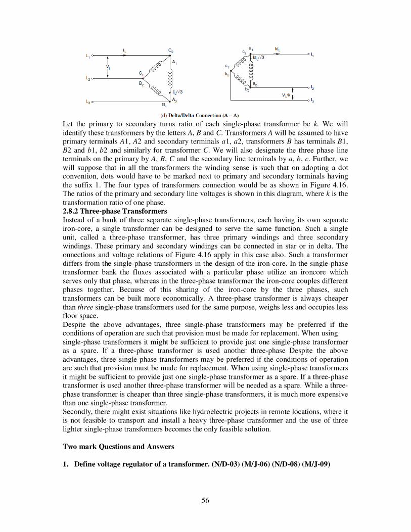
56
Let the primary to secondary turns ratio of each single-phase transformer be k. We will identify these transformers by the letters A, B and C. Transformers A will be assumed to have primary terminals A1, A2 and secondary terminals a1, a2, transformers B has terminals B1, B2 and b1, b2 and similarly for transformer C. We will also designate the three phase line terminals on the primary by A, B, C and the secondary line terminals by a, b, c. Further, we will suppose that in all the transformers the winding sense is such that on adopting a dot convention, dots would have to be marked next to primary and secondary terminals having the suffix 1. The four types of transformers connection would be as shown in Figure 4.16. The ratios of the primary and secondary line voltages is shown in this diagram, where k is the transformation ratio of one phase. 2.8.2 Three-phase Transformers
Instead of a bank of three separate single-phase transformers, each having its own separate iron-core, a single transformer can be designed to serve the same function. Such a single unit, called a three-phase transformer, has three primary windings and three secondary windings. These primary and secondary windings can be connected in star or in delta. The onnections and voltage relations of Figure 4.16 apply in this case also. Such a transformer differs from the single-phase transformers in the design of the iron-core. In the single-phase transformer bank the fluxes associated with a particular phase utilize an ironcore which serves only that phase, whereas in the three-phase transformer the iron-core couples different phases together. Because of this sharing of the iron-core by the three phases, such transformers can be built more economically. A three-phase transformer is always cheaper than three single-phase transformers used for the same purpose, weighs less and occupies less floor space. Despite the above advantages, three single-phase transformers may be preferred if the conditions of operation are such that provision must be made for replacement. When using single-phase transformers it might be sufficient to provide just one single-phase transformer as a spare. If a three-phase transformer is used another three-phase Despite the above advantages, three single-phase transformers may be preferred if the conditions of operation are such that provision must be made for replacement. When using single-phase transformers it might be sufficient to provide just one single-phase transformer as a spare. If a three-phase transformer is used another three-phase transformer will be needed as a spare. While a three-phase transformer is cheaper than three single-phase transformers, it is much more expensive than one single-phase transformer. Secondly, there might exist situations like hydroelectric projects in remote locations, where it is not feasible to transport and install a heavy three-phase transformer and the use of three lighter single-phase transformers becomes the only feasible solution.
Two mark Questions and Answers
1. Define voltage regulator of a transformer. (N/D-03) (M/J-06) (N/D-08) (M/J-09)

57
When a transformer is loaded with a constant primary voltage, the secondary voltage decreases for lagging power factor load, and increases for leading pf load because of its internal resistance and leakage reactance .The change in secondary terminal voltage from no load to full load expressed as a percentage of no loads or full load voltage is termed as regulation. % Regulation down = (0V2-V2) x 100/0V2 % Regulation up = (0V2-V2) x 100/V2
2. Draw the typical equivalent circuit of a single phase transformer. (N/D-03) (N/D-07)
The equivalent circuit diagram for a single phase transformer referred to primary side is shown in Fig.
3. What is in ideal transformer? (A/M-04)
1. The primary and secondary winding having no resistance. 2. No leakage flux. 3. No losses. 4. The core has infinite permeability so that the magnetizing current is needed to
establish the require amount of flux. 5. 100% efficiency.
The transformer having above hypothetical properties it referred as ideal transformer.
4. Define all day efficiency of a transformer. (A/M-04) (N/D-04) (N/D-05) (N/D-06)
All day efficiency or energy efficiency is computed on the basis of energy consumed during a certain time period, usually a day of 24 hrs.
All day efficiency = Output in Kwh Input in Kwh
5. State the different losses which occur in transformer. (N/D-04)
1. Core or iron loss. (It includes both hysteresis loss and eddy current loss). 2. Copper loss

58
6. What is the condition for maximum efficiency and regulation of a transformer?
(A/M-05) (M/J-06)
Condition for maximum efficiency is Copper loss = Iron loss
7. List the various application of an auto transformer. (A/M-05)
To give small boost to a distribution cable to correct for the voltage drop. As induction motor starters. As furnace transformers As interconnecting transformers In control equipment for single phase and 3 phase elective locomotives.
8. What is the application of equivalent circuit of single phase transformer? (N/D-04)
To simplify calculations the transformer represented by its equivalent circuit
9. What is dielectric loss in a transformer? (N/D-06)
The dielectric loss occurs in transformer due to insulation material particularly in oil and solid insulation.
10. What are the components of magnetic losses in transformer and on what factors do
they depend? (M/J-07)
The magnetic losses are hysteresis loss and eddy current loss. These losses depend on flux density and frequency. It is a constant loss.
11. Write down equations for volt ampere transferred inductively and volt ampere
conductively in an auto transformer. (M/J-07)
Volt ampere transferred inductively = Sti =V2 (I2-I1)
Volt ampere transferred conductively = Stc =V2 I1
12. Compare core and shell type transformers. (A/M-08)
In core type, the windings surround the core considerably and in shell type the core surround the winding.
13. Why the efficiency of transformer more than that of other rotating machines? (A/M-
08)
1. In transformer electrical energy is converted into electrical energy 2. There in no moving part in transformer hence no mechanical losses.
Therefore the transformer has more efficiency than that of rotating machines.

59
14. Why the transformer rating expressed in KVA? (N/D-08)
Copper loss of a transformer depends on current and iron loss on voltage. Hence total losses depend on Volt- Ampere and not on the power factor. That is why the rating of transformers is in kVA and not in kW.
15. What are the advantages of auto transformer as compared to two winding
transformer? (M/J-09)
1. Smaller in size 2. Lower cost 3. Better efficiency 4. Less exciting current 5. Better voltage regulation

60
UNIT III SYNCHRONOUS MACHINES 8 Principle of alternators:- Construction details, Equation of induced EMF and Vector diagram -Synchronous motor:- Starting methods, Torque, V curves, Speed control and Hunting. 3.1 INTRODUCTION
It is known that the electric supply used, now a days for commercial as well as domestic
purposes, is of alternating type.Similar to d.c. machines, the a.c. machines associated with
alternating voltages, are also classified as generators and motors.The machines generating
a.c. e.m.f. are called alternators or synchronous generators. While the machine accepting
input from a.c. supply to produce mechanical output are called synchronous motors. Both
these machines work at a specific constant speed called synchronous speed and hence in
general called synchronous machines.All the modern power stations consists of large capacity
three phase alternators. In this chapter, the construction, working principle and the e.m.f.
equation of three phase alternator is discussed.
Difference between D.C. Generator and Alternator
It is seen that in case of a d.c. generator, basically the nature of the induced e.m.f. in the
armature conductors is of alternating type. By using commutator and brush assembly it is
converted to d.c. and made available to the external circuit. If commutator is dropped from a
d.c. generator and induced e.m.f. is tapped from an armature directly outside, the nature of
such e.m.f. will be alternating. Such a machine without commutator, providing an a.c. e.m.f.
to the external circuit is called an alternator. The obvious question is how is it possible to
collect an e.m.f. from the rotating armature without commutator ?
Note : So the arrangement which is used to collect an induced e.m.f. from the rotating
armature and make it available to the stationary circuit is called slip ring and brush assembly.
3.2 CONCEPT OF SLIP RINGS AND BRUSH ASSEMBLY
Whenever there is a need of developing a contact between rotating element and the
stationary circuit without conversion of an e.m.f. from a.c. to d.c., the slip rings and brush
assembly can be used.In case of three phase alternators, the armature consist of three phase
winding and an a.c. e.m.f. gets induced in these windings. After connecting windings in star
or delta, the three ends of the windings are brought out. Across these terminals three phase
supply is available. But the armature i.e. these terminals are rotating and hence stationary
load cannot be connected directly to them. Hence slip rings, made up of conducting material
are mounted on the shaft. Each terminal of winding is connected to an individual slip ring,
permanently. Hence three phase supply is now available across the rotating slip rings. The
brushes are resting on the slip rings, just making contact.
Note : The brushes are stationary. Hence as brushes make contact with the slip rings, the
three phase supply is now available across the brushes which are stationary. Hence any
stationary load can then by connected across these stationary terminals available from the
brushes. The schematic arrangement is shown in the Fig. 3.1.
Not only the induced e.m.f. can be taken out from the rotating winding check outside but an
induced e.m.f. can be injected to the rotating winding from outside with the help of slip ring

61
and brush assembly. The external voltage can be applied across the brushes, which gets
applied across the rotating due to the springs.Now the induced e.m.f. is basically the effect of
the relative motion present between an armature and the field. Such a relative motion is
achieved by rotating armature with the help of prime mover, in case of a d.c. generator. As
armature is connected to commutator in a d.c. generator, armature must be rotating member
while field as a stationary. But in case of alternators it is possible to have,
1) The rotating armature and stationary field.
2) The rotating field and stationary armature.
Fig. 3.1 Arrangement of slip rings
Note : But practically most of the alternators prefer rotating field type construction with
stationary armature due to certain advantages.
Advantages of Rotating Field Over Rotating Armature
The various advantages of rotating field can be stated as,
1) As everywhere a.c. is used, the generation level of a.c. voltage may be higher as 11 KV to
33 KV. This gets induced in the armature. For stationary armature large space can be
provided to accommodate large number of conductors and the insulations.
2) It is always better to protect high voltage winding from the centrifugal forces caused due to
the rotation. So high voltage armature is generally kept stationary. This avoids the interaction
of mechanical and electrical stresses.
3) It is easier to collect larger currents at very high voltage from a stationary member than
from the slip ring and brush assembly. The voltage required to be supplied to the field is very
low (110 V to 220 V d.c.) and hence can be easily supplied with the help of slip ring and
brush assembly by keeping it rotating.
4) The problem of sparking at the slip rings can be avoided by keeping field rotating which is
low voltage circuit and high voltage armature as stationary.
5) Due to low voltage level on the field side, the insulation required is less and hence field
system has very low inertia. It is always better to rotate low inertia system than high inertia,
as efforts required to rotate low inertia system are always less.

62
6) Rotating field makes the overall construction very simple. With simple, robust mechanical
construction and low inertia of rotor, it can be driven at high speeds. So greater output can
obtained from an alternator of given size.
7) If field is rotating, to excite it be external d.c. supply two slip rings are enough. Once each
for positive and negative terminals. As against this, in three phase rotating armature the
minimum number of slip rings required are three and can not be easily insulated due to high
voltage levels.
8) The ventilation arrangement for high voltage side can be improved if it is kept stationary.
Due to all these reasons the most of the alternators in practice use rotating field type of
arrangement. For small voltage rating alternators rotating armature arrangement may be used.
3.3 CONSTRUTION OF SYNCHRONOUS GENERATOR (STATOR AND ROTOR)
Most of the alternators prefer rotating field type of the construction. In case of alternators
the winding terminology is slightly different than in case of d.c. generators. In alternators the
stationary winding is called 'Stator' while the rotating winding is called 'Rotor'
Note : so most of alternator have stator as armature and rotor as field, in
practice.Constructional details of rotating field type of alternator are discussed below.
3.3.1 Stator The stator is a stationary armature. This consists of a core and the slots to hold the armature
winding similar to the armature of a d.c. generator. The stator core uses a laminated
construction. It is built up of special steel stampings insulated from each other with varnish or
paper. The laminated construction is basically to keep down eddy current losses. Generally
choice of material is steel to keep down hysteresis losses.
Fig. 3.2 Section of an alternator stator
The entire core is fabricated in a frame made of steel plates. The core has slots on its
periphery for housing the armature conductors. Frame does not carry any flux and serves as
the support to the core. Ventilation is maintained with the help of holes cast in the frame. The
section of an alternators stator is shown in the Fig. 3.1.
3.3.2 Rotor There are two types of rotors used in alternators,
1) Salient pole type, and 2) Smooth cylindrical type.
Salient Pole Type

63
This is also called projected pole type as all the poles are projected out from the
surface of the rotor.
The poles are built up of thick steel laminations. The poles are bolted to the rotor as shown in
the Fig. 3.3. The pole face has been given a specific shape. The field winding is provided on
the pole shoe. These rotors have large diameter and small axial length. The limiting factor
fore the size of the rotor is the centrifugal force acting on the rotating member of the
machine. As mechanical strength of salient pole type is less, this is preferred for low speed
alternators ranging from 125 r.p.m. to 500 r.p.m. The prime movers used to drive such rotor
are generally water turbines and I.C. engines.
Fig.3.3 Salient pole type rotor
Smooth Cylindrical Type
This is also called non-salient type or non-projected pole type or round rotor
construction. The Fig. 3.4 shows smooth cylindrical type of rotor.
Fig. 3.4 Smooth cylindrical rotor
The rotor consists of small solid steel cylinder, having number of slots to accommodate the
field coil. The slots are covered at the top with the help of steel or manganese wedges. The
unslotted portions of the cylinder itself act as the poles. The poles are not projecting out and
the surface of the rotor is smooth which maintains uniform air gap between stator and the
rotor. These rotors have small diameters and large axial lengths. This is to keep peripheral
speed within limits. The main advantage of this type is that these are mechanically very
strong and thus preferred for high speed alternators ranging between 1500 to 3000 r.p.m.
Such high speed alternators are called 'turboalternators'. The prime movers used to drive such
type of rotors are generally steam turbines, electric motors.
Difference between Salient and Cylindrical Type of Rotor:

64
3.3.3 Excitation System
The synchronous machines whether alternator or motor are necessarily separately excited
machines. Such machines always require d.c. excitation for their operation. The field systems
are provided with direct current which is supplied by a d.c. source at 125 to 600 V. In many
cases the exciting current is obtained from a d.c. generator which is mounted on the same
shaft of that of alternator. Thus excitation systems are of prime importance. Many of the
conventional system involves slip rings, brushes and commutators.
Brushless Excitation System
With the increase in rating of alternator, the supply of necessary magnetic field becomes
difficult as the current values may reach upto 4000 A. If we use conventional excitation
systems such as a d.c. generator whose output is supplied to the alternator field through
brushes and slip rings then problems are invariable associated with slip rings commutators
and brushes regarding cooling and maintenance. Thus modern excitation systems are
developed which minimizes thees problems by avoiding the use of brushes. Such excitation
system is called brushless excitation system which is shown in the Fig. 3.5
Fig. 3.5 Brushless Excitation system

65
It consists of silicon diode rectifier which is mounted on the same shaft of alternator and will
directly provide necessary excitation to the field. The power required for rectifiers is provided
by an a.c. excitor which is having stationary field but rotating armature.The field of an excitor
is supplied through a magnetic amplifier which will control and regulate the output voltage of
the alternator since the feedback of output voltage of alternator is taken and given to the
magnetic amplifier. The system can be made self-contained if the excitation power for the
magnetic amplifier is obtained from the main shaft. The performance and design of the
overall system can be optimized by selecting proper frequency and voltage for a.c. excitor.
The additional advantage that can be obtained with this system is that it is not necessary to
make arrangement for space excitors, generators-field circuit breakers and field rheostats.
3.3.4 Methods of Ventilation
1)Natural of Ventilation: A fan is attached to either ends of the machine. The ventilation
medium is nothing but an atmospheric air which is forced over the machine parts, carrying
away the heat. This circulation is possible with or without ventilating ducts. The ventilating
ducts if provided may be either axial or radial.
2) Closed Circuit Ventilation System: An atmospheric air may contain injurious elements
like dust, moisture, and acidic fumes etc. which are harmful for the insulation of the winding.
Hence for large capacity machined closed circuit system is preferred for ventilation. The
ventilating medium used is generally hydrogen. The hydrogen circulated over the machine
parts is cooled with the help of water cooled heat exchangers. Hydrogen provides very
effective cooling than air which increases the rating of the machine upto 30 to 40% for the
same size. All modern alternators use closed circuit ventilation with the help of hydrogen as a
ventilation medium.
3.4 Working Principle of Synchronous Generator
The alternators work on the principle of electromagnetic induction. When is a relative
motion between the conductors and the flux, e.m.f. gets induced in the conductors. The d.c.
generators also work on the same principle. The only difference in practical alternator and a
d.c. generator is that in an alternator the conductors are stationary and field is rotating. But
for understanding purpose we can always consider relative motion of conductors with respect
to the flux produced by the field winding.Consider a relative motion of a single conductor
under the magnetic field produced by two stationary poles. The magnetic axis of the two
poles produced by field is vertical, shown dotted in the Fig.3.6.
Fig. 3.6 Two pole alternator

66
Let conductor starts rotating from position 1. At this instant, the entire velocity component is
parallel to the flux lines. Hence there is no cutting of flux lines by the conductor. So dΦ/dt at
this instant is zero and hence induced e.m.f. in the conductor is also zero.As the conductor
moves from position 1 towards position 2, the part of the velocity component becomes
perpendicular to the flux lines and proportional to that, e.m.f. gets induced in the conductor.
The magnitude of such an induced e.m.f. increases as the conductor moves from position 1
towards 2. At position 2, the entire velocity component is perpendicular to the flux lines.
Hence there exists maximum cutting of the flux lines. And at this instant, the induced e.m.f.
in the conductor is at its maximum. As the position of conductor changes from 2 towards 3,
the velocity component perpendicular to the flux starts decreasing and hence induced e.m.f.
magnitude also starts decreasing. At position 3, again the entire velocity component is
parallel to the flux lines and hence at this instant induced e.m.f. in the conductor is zero.
As the conductor moves from 3 towards 4, the velocity component perpendicular to the flux
lines again starts increasing. But the direction of velocity component now is opposite to the
direction of velocity component existing during the movement of the conductor from position
1 to 2. Hence an induced e.m.f. in the conductor increases but in the opposite direction.At
position 4, it achieves maxima in the opposite direction, as the entire velocity component
becomes perpendicular to the flux lines.Again from position 4 to 1, induced e.m.f. decreased
and finally at position 1, again becomes zero. This cycle continues as conductor rotates at a
certain speed. So if we plot the magnitudes of the induced e.m.f. against the time, we get an
alternating nature of the induced e.m.f. as shown in the Fig. 3.7.
Fig.3.7 Alternating nature of the induced e.m.f.
3.4.1 Mechanical and Electrical Angle
We have seen that for 2 pole alternator, one mechanical revolution corresponds to one
electrical cycle of an induced e.m.f. Now consider 4 pole alternator i.e. the field winding is
designed to produce 4 poles. Due to 4 poles, the magnetic axis exists diagonally shown dotted
in the Fig. 3.8.

67
Fig.3.8 Mechanical and Electrical Angle.
Now in position 1 of the conductor, the velocity component is parallel to the flux lines while
in position 2, there is gathering of flux lines and entire velocity component is perpendicular to
the flux lines. So at position 1, the induced e.m.f. in the conductors is zero while at position 2,
it is maximum. Similarly as conductor rotates, the induced e.m.f. will be maximum at
position 4, 6 and 8 and will be minimum at position 3, 5 and 7. So during one complete
revolution of the conductor, induced e.m.f. will experience four times maxima, twice in either
direction and four times zero. This is because of the distribution of flux lies due to existence
of four poles.So if we plot the nature of the induced e.m.f; for one revolution of the
conductor, we get the two electrical cycles of the induced e.m.f., as shown in the Fig. 3.9
Fig.3.9 Mechanical and Electrical Angle.
Note : Thus the degrees electrical of the induced e.m.f. i.e. number of cycles of the induced
e.m.f. depends on the number of poles of an alternator. So for a four pole alternator we can
write, 360o mechanical = 720o electrical. From this we can establish the general relation
between degrees mechanical and degrees electrical as,
360o mechanical = 360o x (p/2) electrical Where P = Number of poles
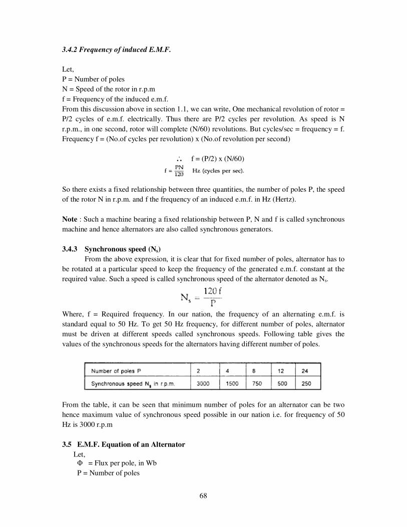
68
3.4.2 Frequency of induced E.M.F.
Let,
P = Number of poles
N = Speed of the rotor in r.p.m
f = Frequency of the induced e.m.f.
From this discussion above in section 1.1, we can write, One mechanical revolution of rotor =
P/2 cycles of e.m.f. electrically. Thus there are P/2 cycles per revolution. As speed is N
r.p.m., in one second, rotor will complete (N/60) revolutions. But cycles/sec = frequency = f.
Frequency f = (No.of cycles per revolution) x (No.of revolution per second)
... f = (P/2) x (N/60)
So there exists a fixed relationship between three quantities, the number of poles P, the speed
of the rotor N in r.p.m. and f the frequency of an induced e.m.f. in Hz (Hertz).
Note : Such a machine bearing a fixed relationship between P, N and f is called synchronous
machine and hence alternators are also called synchronous generators.
3.4.3 Synchronous speed (Ns)
From the above expression, it is clear that for fixed number of poles, alternator has to
be rotated at a particular speed to keep the frequency of the generated e.m.f. constant at the
required value. Such a speed is called synchronous speed of the alternator denoted as Ns.
Where, f = Required frequency. In our nation, the frequency of an alternating e.m.f. is
standard equal to 50 Hz. To get 50 Hz frequency, for different number of poles, alternator
must be driven at different speeds called synchronous speeds. Following table gives the
values of the synchronous speeds for the alternators having different number of poles.
From the table, it can be seen that minimum number of poles for an alternator can be two
hence maximum value of synchronous speed possible in our nation i.e. for frequency of 50
Hz is 3000 r.p.m
3.5 E.M.F. Equation of an Alternator
Let, Φ = Flux per pole, in Wb
P = Number of poles

69
Ns = Synchronous speed in r.p.m.
f = Frequency of induced e.m.f. in Hz
Z = Total number of conductors
Zph = Conductors per phase connected in series
Zph = Z/3 as number of phases = 3.
Consider a single conductor placed in a slot. The average value of e.m.f. induced in a
conductor = dΦ/dt. For one revolution of a conductor,
eavg per conductor = (Flux cut in one revolution)/(time taken for one revolution)
Total flux cut in one revolution is Φ x P
Time taken for one revolution is 60/Ns seconds.
eavg per conductor = ΦP / (60/Ns)
= Φ (PNs/60) ............. (1)
But f = PNs/6120
PNs/60 = 2f
Substituting in (1),
eavg per conductor = 2 f Φ volts
Assume full pitch winding for simplicity i.e. this conductor is connected to a conductor which
is 180o electrical apart. So there two e.m.f.s will try to set up a current in the same direction
i.e. the two e.m.f. are helping each other and hence resultant e.m.f. per turn will be twice the
e.m.f. induced in a conductor.
... e.m.f. per turn = 2 x (e.m.f. per conductor)
= 2 x (2 f Φ)
= 4 f Φ volts
Fig.3.10 Single turn in generator.
Let Tph be the total number of turn per phase connected in series. Assuming concentrated
winding, we can say that all are placed in single slot per pole per phase. So induced e.m.f.s in
all turns will be in phase as placed in single slot. Hence net e.m.f. per phase will be algebraic
sum of the e.m.f.s per turn.
... Average Eph = Tph x (Average e.m.f. per turn)
... Average Eph = Tph x 4 f Φ

70
But in a.c. circuits R.M.S. value of an alternating quantity is used for the analysis. The form
factor is 1.11 of sinusoidal e.m.f.
Kf = (R.M.S.)/Average = 1.11 ......... for sinusoidal
R.M.S. value of Eph = K x Average value
E = 4.44 x f Φ Tph volts ........... (2)
Note : This is the basic e.m.f. equation for an induced e.m.f. per phase for full pitch,
concentrated type of winding. Where Tph = Number of turns per phase.
Tph = Zph /2 ....... as 2 conductors constitute 1 turn
But as mentioned earlier, the winding used for the alternators is distributed and short pitch
hence e.m.f. induced slightly gets affected. Let us see now the effect of distributed and short
pitch type of winding on the e.m.f. equation.
3.5.1 Pitch Factor or Coil Span Factor (Kc)
In practice short pitch coils are preferred. So coil is form by connecting one coil side
to another which is less than one pole pitch away. So actual span is less than 180o . The coil is
generally shorted by one or two slots.
Note : The angle by which coil are short pitched is called angle or short pitched is called
angle of short pitch denoted as 'α'. Where α is the angle by which coils are short pitched.
As coils are shorted in terms of number of slots i.e. either by one slot, two slots and so on and
slot angle is β then angle of short pitch is always a multiple of the slot angle β.
Fig.3.11 Short pitched coil.
... α = β x Number of slots by which coils are short pitched.
Or α = 180o -Actual coil span of the coils.
This is shown in the Fig. 3.11. Now let E be the induced e.m.f. in each coil side. If coil is full
pitch coil, the induced e.m.f. in each coil side help each other. Coil connections are such that
both will try to set up a current in the same direction in the external circuit. Hence the
resultant e.m.f. across a coil will be algebraic sum of the two.
... ER = E + E = 2E .......... for full pitch

71
Fig.3.12 Full pitched coil.
Now the coil is short pitched by angle 'α', the two e.m.f. in two coil sides no longer remains
in phase from external circuit point of view. Hence the resultant e.m.f. is also no longer
remains algebraic sum of the two but becomes a phasor sum of the two as shown in the Fig.
3.
Fig.3.13Phasor sum of two emfs.
Obviously ER in such a case will be less than what it is in case of full pitch coil. From the
geometry of the Fig. 3, we can write, AC is perpendicular drawn on OB bisecting OB.
... l (OC) = l (CB) = ER /2
∟BOA = α/2
... cos (α/2) = OC/OA = ER/2E
... ER = 2 E cos (α/2) ............... For short pitch
This is the resultant e.m.f. in case of a short pitch coil which depends on the angle of short
pitch 'α'.
Note : Now the factor by which, induced e.m.f. gets reduced due to short pitching is called
pitch factor or coil span factor denoted by Kc. It is defined as the ratio of resultant e.m.f.
when coil is short pitch to the resultant e.m.f. when coil is full pitched. It is always less than
one.
Where α = Angle of short pitch
3.5.2 Distribution Factor (Kd)

72
Similar to full pitch coils, concentrated winding is also rare in practice. Attempt is made
to use all the slots available under a pole for the winding which makes the nature of the
induced e.m.f. more sinusoidal. Such a winding is called distributed winding.
Consider 18 slots, 2 pole alternator. So slots per pole i.e. n = 9.
m = Slots per pole per phase = 3
β = 180o /9 = 20o
Let E = Induced e.m.f. per coil and there are 3 coils per phase. In concentrated type all the
coil sides will be placed in one slot under a pole. So induced e.m.f. in all the coils will
achieve maxima and minima at the same time i.e. all of them will be in phase. Hence
resultant e.m.f. after connecting coils in series will be algebraic sum of all the e.m.f.s. as all
are in phase. As against this, in distributed type, coil sides will be distributed, one each in the
3 slots per phase available under a pole as shown in the Fig. 3.14(a).
Fig.3.14 Distributed and Phase difference betweeninduced emf.Thought the magnitude of e.m.f. in each coil will be same as 'E', as each slot contributes
phase difference of βo i.e. 20o in this case, there will exist a phase difference of βo with
respect to each other as shown in the Fig. 1(b). Hence resultant e.m.f. will be phasor sum of
all of them as shown in the the Fig. 2. So due to distributed winding resultant e.m.f.
decreases.
Fig.3.14 Phase sum of induced emf Note : The factor by which there is a reduction in the e.m.f. due to distribution of coils is
called distribution factor denoted as Kd.
Let us see the derivation for its expression. In general let there be 'n' slots per pole and 'm'
slots per pole per phase. So there will be 'm' coils distributed under a pole per phase,
connected in series. Let E be the induced e.m.f. per coil. Then all the 'm' e.m.f.s induced in
the coils will have successive phase angle difference of β = 180o/n. While finding out the
phasor sum of all of them, phasor diagram will approach a shape of a 'm' equal sided polygon
circumscribed by a semicircle of radius 'R'.This is shown in the Fig. 3.15. AB, BC, CD etc,
represents e.m.f. per coil. All the ends joined at 'O' which is center of the circumscribing
semicircle of raduis 'R'.

73
Fig. 3.15 Phasor sum of 'm' e.m.f.s
Angle subtended by each phasor at the origin 'O' is βo. This can be proved as below. All the
triangles OAB, OBC .... are similar and isosceles, as AB = BC = CD = ... = E.
∟OAB = ∟OBA = ∟OBC = .... = x
∟AOB = ∟BOC = ... = y say
Now in ∆ OAB, 2x + y = 180
while ∟OBA + ∟OBC + β = 180o ................. (3)
i.e. 2x + β = 180o
Comparing (3) and (4), y = β
So ∟AOB = ∟BOC = ∟COD = ... = β
If 'M' is the last point of the last phasor,
∟AOM = m x β = mβ
and AM = ER = Resultant of all the e.m.f.s.
Consider a ∆OAB separately as shown in the Fig. 4. Let OF be the perpendicular drawn on
AB bisecting angle at apex 'O' as β/2.
Fig. 3.16angle of OAB

74
l (AB) = E
l (AF) = E/2
and l (OA) = R
... sin (β/2) = AF/OA = (E/2)/R
... E = 2R sin (β/2) ........... (5)
Now consider ∆ OAM as shown in the Fig. . 3 and OG is the perpendicular drawn from 'O'
on its base bisecting ∟OAM.
... ∟AOG = ∟GOM = (mβ)/2
... l (AM) = E
... l (AG) = E/2
= 2 (OA) sin (mβ/2)
Arithmetic sum of e.m.f.s = Arc AB = OA x (mβ)
Note : The angle (mβ/2) in the denominator must be in radians. The above formula is used to
calculate distribution factor when phase spread is and the winding is uniformly distributed.
3.5.3 Generalized Expression for E.M.F. Equation of an Alternator
Considering full pitch, concentrated winding.
Eph = 4.44 f Φ Tph Volts.
Generalized expression for e.m.f. equation can be written as
For full pitch coil, Kc = 1. For concentrated winding Kd = 1.
Note : For short pitch and distributed winding Kc and Kd are always less than unity.
Example 1 : An armature of a three phase alternators has 120 slots. The alternator has 8
poles. Calculate its distribution factor.
Solution :
n = Slots/Pole = 120/8 = 15
m = slots/pole/phase = n/3 = 15/3 = 5

75
β = 180o/n = 180o/5 = 12o
= 0.957
Example 2: In a 4 pole, 3 phase alternator, armature has 36 slots. It is using an armature
winding which is short pitched by one slot. Calculate its coil span factor.
Solution :
n = Slots/pole = 36/4 = 9
β = 180o/ = 20o
Now coil is shorted by 1 slot i.e. by 20o to full pitch distance.
... α = Angle of short pitch = 20o
... Kc = cos (α/2) = cos (10)
= 0.9848
3.5.4 Line Value of Induced E.M.F
If the armature winding of three phase alternator is start connected, then the value of
induced e.m.f. across the terminals is √3Eph where Eph is induced e.m.f. per phase.While if it
is delta connected line value of e.m.f. is same as Eph .This is shown in the Fig. 3.17(a) and (b).
Fig. 3.17 Line value of induced emf with different connections
Practically most of the alternators are star connected due to following reasons:
1. Neutral point can be earthed from safety point of view.
2. For the same phase voltage, available across the terminal is more than delta
connection.
3. For the same terminal voltage, the phase voltage in star is 1/√3 times line value.
This reduces strains on the insulation of the armature winding.
Example 3 : An alternator runs at 250 r.p.m. and generates an e.m.f. at 50 Hz. There are 216
slots each containing 5 conductors. The winding is distributed and full pitch. All the
conductors of each phase are in series and flux per pole is 30 mWb which is sinusoidally

76
distributed. If the winding is star connected, determine the value of induced e.m.f. available
across the terminals.
Solution :
Ns = 250 r.p.m. , f = 50 Hz
Ns = 120f/P
... 250 = (120 x 50)/P
... P = 24
... n = Slots/Pole = 216/24 = 9
... m = n/3 = 3
β = 180o/9 = 20o
= 0.9597
Kc = 1 as full pitch coils.
Total no. of conductors Z = 216 x 5 = 1080
... Zph = Z/3 = 1080/3 = 360
Tph = Zph/2 ..... 2 conductors → 1 turn
= 360/2 = 180
... Eph = 4.44 Kc Kd f Φ Tph.
= 4.44 x 1 x 0.9597 x 30 x 10-3 x 50 x 180
= 1150.48 V
Eline = √3 Eph ........... star connection
= √3 x 1150.48
= 1992.70 V.
Example 4 : A 3 phase, 16 pole, star connected alternators has 144 slots on the armature
periphery. Each slot contains 10 conductors. It is driven at 375 r.p.m. The line value of e.m.f.
available across the terminals is observed to be 2.657 kV. Find the frequency of the induced
e.m.f. and flux per pole.
Solution :
P = 16, Ns = 375 r.p.m.
Slots = 144, Conductors / slots = 10
Eline = 2.657 kV
Ns = 120f/P
... 375 = (120 x f)/16
... f = 50 Hz
Assuming full pitch winding , Kc = 1
... n = Slots/pole = 144/16
= 9
... m = n/3
= 3

77
... β = 180o/9
= 20o
= 0.9597
Total conductors = Slots x condutors/Slot
i.e. Z = 144 x 10 = 1440
... Zph = Z/3 = 1440/3
= 480
Tph = Zph /2 = 480/2
= 240
Eph = Eline/√3 = 2.657/√3 = 1.534 kV
Now Eph = 4.44 Kc Kd f Φ Tph .
.. 1.534 x 10-3 = 4.44 x 1 x 0.9597 x Φ x 50 x 240
... Φ = 0.03 Wb = 30 mWb
3.6 Armature Reaction
When the load is connected to the alternator, the armature winding of the alternator carries a current. Every current carrying conductor produces its own flux so armature of the alternator also produces its own flux, when carrying a current. So there are two fluxes present in the air gap, one due to armature current while second is produced by the filed winding called main flux. The flux produced by the armature is called armature flux. Note : So effect of the armature flux on the main flux affecting its value and the distribution is called armature reaction. The effect of the armature flux not only depends on the magnitude of the current flowing through the armature winding but also depends on the nature of the power factor of the load connected to the alternator.Now we will study the effect of nature of the load power factor on the armature reaction.
3.6.1 Unity Power Factor Load
Consider a purely resistive load connected to the alternator, having unity power factor. As induced e.m.f. Eph drives a current of Iaph and load power factor is unity, Eph and Iph
are in phase with each other. If Φf is the main flux produced by the field winding responsible for producing Eph then Eph
lags Φf by 90o .Now current through armature Ia, produces the armature flux say Φa. So flux Φa and Ia are always in the same direction.This relation between
Fig. 3.18 Armature reaction for unity power factor

78
It can be seen from the phasor diagram that there exists a phase difference of 90o between the armature flux and the main flux. The waveforms for the two fluxes are also shown in the Fig. 3.18. From the waveforms it can be seen that the two fluxes oppose each other on the left half of each pole while assist each other on the right half of each pole. Hence average flux in the air gap remains constant but its distribution gets distrorted. Note : Hence such distorting effect of armature reaction under unity p.f. condition of the load is called cross magnetising effect of armature reaction.Due to such distortion of the flux, there is small drop in the terminal voltage of the alternator. 3.6.2 Zero Lagging Power Factor Load
Consider a purely inductive load connected to the alternator having zero lagging power factor. This indicates that Iaph driven by Eph lags Eph by 90o which is the power factor angle Φ.Induced e.m.f. Eph lags main flux Φf by 90o while Φa is in the same direction as that of Ia. So the phasor diagram and the waveforms are shown in the Fig.3.19. It can be seen from the phasor diagram that the armature flux and the main flux are exactly in opposite direction to each other.
Note : So armature flux tries to cancel the main flux. Such an effect of armature reaction is called demagnetising effect of the armature reaction.As this effect causes reduction in the main flux, the terminal voltage drops. This drop in the terminal voltage is more than the drop corresponding to the unity p.f. load.
Fig. 3.19 Armature reaction for zero lagging p.f. load
3.6.3 Zero Leading Power Factor Load Consider a purely capacitive load connected to the alternator having zero leading
power factor. This means that armature current Iaph driven by Eph, leads Eph by 90o, which is the power factor angle Φ. Induced e.m.f. Eph lags Φf by 90o while Iaph and Φa are always in the same direction. The phasor diagram and the waveforms are shown in the Fig. 3.20.
Fig. 3.20 Armature reaction for zero leading p.f. load

79
It can be seen from the phasor diagram and waveforms shown in the Fig. 2, the armature flux and the main field flux are in the same direction i.e. they are helping each other. This results into the addition in main flux.
Note : Such an effect of armature reaction due to which armature flux assists field flux is called magnetising effect of the armature reaction.As this effect adds the flux to the main flux, greater e.m.f. gets induced in the armature. Hence there is increase in the terminal voltage for leading power factor loads. For intermediate power factor loads i.e. between zero lagging and zero leading the armature reaction is partly cross magnetising and partly demagnetising for lagging power factor loads or partly magnetising for leading power factor loads.
3.6.4 Armature Reaction Reactance (Xar) In all the conditions of the load power factors, there is change in the terminal voltage
due to the armature reaction. Mainly the practical loads are inductive in nature, due to demagnetising effect of armature reaction, there is reduction in the terminal voltage. Now this drop in the voltage due to the interaction of armature and main flux. This drop is not across any physical element.But to quantify the voltage drop due to the armature reaction, armature winding is assumed to have a fictitious reactance. This fictitious reactance of the armature is called armature reaction reactance denoted as Xar Ω/ph. And the drop due to armature reaction can be accounted as the voltage drop across this reactance as Iar Xar. Note : The value of this reactance changes as the load power factor changes, as armature reaction depends on the load power factor. 3.7 Concepts of Synchronous Reactance and Impedance
The sum of fictitious armature reaction reactance accounted for considering armature reaction effect and the leakage reactance of the armature called synchronous reactance of the alternator demoted as Xs. So
Xs = XL + Xar Ω/ph As both XL and Xar are ohmic values per phase, synchronous reactance is also specified as ohms per phase.Now from this, it is possible to define an impedance of the armature winding. Such an impedance obtained by combining per phase values of synchronous reactance and armature resistance is called synchronous impedance of the alternator denoted as Zs. So
Zs = Ra + j Xs Ω/ph
| Zs | = √ (Ra2 + j (Xs)
2
For getting a standard frequency, alternator is to be driven at synchronous speed. So word synchronous used in specifying the reactance and impedance is referred to the working speed of the alternator. Generally impedance of the winding is constant but in case of alternator, synchronous reactance depends on the load and its power factor condition, hence synchronous impedance also varies with the load and its power factor conditions. 3.8 Voltage Regulation of an Alternator
Under the load condition, the terminal voltage of alternator is less than the induced e.m.f. Eph. So if load is disconnected , Vph will change from Vph to Eph, if flux and speed is maintained constant. This is because when load is disconnected, Ia is zero hence there are no

80
voltage drops and no armature flux to cause armature reaction. This change in the terminal voltage is significant in defining the voltage regulation. Note : The voltage regulation of an alternator is defined as the change in its terminal voltage when full load is removed, keeping field excitation and speed constant, divided by the rated terminal voltage., So if, Vph = Rated terminal voltage Eph = No load induced e.m.f. the voltage regulation is defined as,
The value of the regulation not only depends on the load current but also on the power factor of the load. For lagging and unity p.f. conditions there is always drop in the terminal voltage hence regulation values are always positive. While for leading capacitive load conditions, the terminal voltage increases as load current increases. Hence regulation is negative in such cases. The relationship between load current and the terminal voltage is called load characteristics of an alternator. Such load characteristics for various load power factor conditions are shown in Fig.3.21.
Fig. 3.21 Load characteristics of an alternator
3.8.1 KVA Rating of an Alternator
The alternators are designed to supply a specific voltage to the various loads. This voltage is called its rated terminal voltage denoted as VL. The power drawn by the load depends on its power factor. Hence instead of specifying rating of an alternator in watts, it is specified in terms of the maximum apparent power which it can supply to the load. In three phase circuits, the apparent power is √3VL IL, measured in VA (volt amperes). This is generally expressed in kilo volt amperes and is called kVA rating of an alternator where IL is the rated full load current which alternator can supply. So for a given rated voltage and kVA rating of an alternator, its full load rated current can be decided. Consider 60 kVA, 11 kV three phase alternator,
In this case kVA rating = 60
........ 10-3 to express the product in kilo volt amperes
... 60 = √3 x 11 x 103 x IL x 10-3
... IL = 3.15 A

81
This is the rated full load current of an alternator. But load current is same as the armature current. So from kVA rating, it is possible to determine full load armature current of an alternator which is important in predicating the full load regulation of an alternator for various power factor conditions. Similarly if load condition is different than the full load, the corresponding armature current can be determined from its full load value.
Note : Ia at half load = 1/2 x Ia at full load. It reduces in the same proportion in which load condition reduces.Hence regulation at any p.f. and at any load condition can be determined. 3.8.2 Regulation of Synchronous Generator
The regulation of an alternator can be determined by various methods. In case of small capacity alternators it can be determined by direct loading test while for large capacity alternators it can be determined by synchronous impedance method.The synchronous impedance method has some short comings. Another method which is popularly used is ampere-turns method. But this method also has certain disadvantages. The disadvantages of these two methods are overcome in a method called zero power factor method. Another important theory which gives accurate results is called Blondel's two reaction theory. Thus there are following methods available to determine the voltage regulation of an alternator,
1. Direct loading method 2. Synchronous impedance method or E.M.F. method 3. Ampere-turns method or M.M.F. method 4. Zero power factor method or potier triangle method 5. ASA modified from of M.M.F. method 6. Two reaction theory
a. Voltage Regulation by Direct Load
The Fig. 3.22 shows the circuit diagram for conducting the direct loading test on the three phase alternator. The star connected armature is to be connected to a three phase load with the help of triple pole single throw (TPST) switch. The field winding is excited by separate d.c. supply. To control the flux i.e. the current through field winding, a rheostat is inserted in series with the field winding. The prime mover is shown which is driving the alternator at its synchronous speed.
Procedure : The alternator is first driven at its synchronous speed Ns by means of a prime mover. Now Eph α Φ ..... (From e.m.f. equation) By giving d.c. supply to the field winding, the field current is adjusted to adjust the flux
so that rated voltage is available across the terminals. This can be observed on the voltmeter connected across the lines. The load is then connected by means of a TPST switch. The load is then increased so that ammeter reads rated value of current. This is full load condition of the alternator. Again adjust the voltage to its rated value by means of field excitation using a rheostat connected. The throw off the entire load by opening the TPST switch, without changing the speed and the field excitation. Observe the voltmeter reading. As load is thrown off, there is no armature current and associated drops. So the voltmeter reading in this situation indicates the value of internally induced e.m.f. called no load terminal voltage.

82
Fig. 3.22 Circuit diagram for direct loading test on alternator
Convert both the reading to phase values. The rated voltage on full load is Vph while reading when load is thrown off is Eph. So by using the formula,the full load regulation of the alternator can be determined. The value of the regulation obtained by this method is accurate as a particular load at required p.f. is actually connected to the alternator to note down the readings.
Note : But for high capacity alternators, that much full load cannot be simulated or directly connected to the alternator. Hence method is restricted only for small capacity alternators.
Example: While supplying a full load, running at synchronous speed, the terminal voltage of an alternator is observed to be 1100 V. When the load is thrown off, keeping field excitation and speed constant, the terminal voltage is observed to be 1266 V. Assuming star connected alternator, calculate its regulation on full load.
Solution : On full load, terminal voltage is 1100 V.
So VL = 1100 V ... Vph = VL/√3 = 635.0853 V
When load is thrown off, VL = 1266 V. But on no load, VL = Eline
... Eline = 1266 V
... Eph = 1266/√3
= 730.925 V
b. Synchronous Impedance Method or E.M.F. Method

83
The method is also called E.M.F. method of determining the regulation. The method requires following data to calculate the regulation.
1. The armature resistance per phase (Ra). 2. Open circuit characteristics which is the graph of open circuit voltage against
the fieldcurrent.This is possible by conducting open circuit test on the alternator. 3. Short circuit characteristics which is the graph of short circuit current against field current.Thisis possible by conducting short circuit test on the alternator.
Let us see, the circuit diagram to perform open circuit as well as short circuit test on the alternator. The alternator is coupled to a prime mover capable of driving the alternator at its synchronous speed. The armature is connected to the terminals of a switch. The other terminals of the switch are short circuited through an ammeter. The voltmeter is connected across the lines to measure the open circuit voltage of the alternator.The field winding is connected to a suitable d.c. supply with rheostat connected in series. The field excitation i.e. field current can be varied with the help of this rheostat. The circuit diagram is shown in the Fig. 3.23.
Fig. 3.23 Circuit diagram for open circuit and short circuit test on alternator
Open Circuit Test: Procedure to conduct this test is as follows: i) Start the prime mover and adjust the speed to the synchronous speed of the alternator.
ii) Keeping rheostat in the field circuit maximum, switch on the d.c. supply.
iii) T .P.S.T switch in the armature circuit is kept open
iv) With the help of rheostat, field current is varied from its minimum value to the rated
value. Due to this, flux increasing the induced e.m.f. Hence voltmeter reading, which is measuring line value of open circuit voltage increases. For various values of field current, voltmeter readings are observed.
The observation for open circuit test are tabulated as below.
Observation table for open circuit test :

84
From the above table, graph of (Voc)ph against If is plotted.
Note: This is called open circuit characteristics of the alternator, called O.C.C. This is shown in the Fig.3.24.
Fig. 3.24 O.C.C. and S.C.C. of an alternator
Short Circuit Test After completing the open circuit test observation, the field rheostat is brought to maximum position, reducing field current to a minimum value. The T.P.S.T switch is closed. As ammeter has negligible resistance, the armature gets short circuited. Then the field excitation is gradually increased till full load current is obtained through armature winding. This can be observed on the ammeter connected in the armature circuit. The graph of short circuit armature current against field current is plotted from the observation table of short circuit test. This graph is called short circuit characteristics, S.C.C. This is also shown in the Fig. 3.24.
Observation table for short circuit test :
The S.C.C. is a straight line graph passing through the origin while O.C.C. resembles B-H curve of a magnetic material.

85
Note : As S.C.C. is straight line graph, only one reading corresponding to full load armature current along with the origin is sufficient to draw the straight line.
The synchronous impedance of the alternator changes as load condition changes. O.C.C. and S.C.C. can be used to determine Zs for any load and load p.f. conditions.In short circuit test, external load impedance is zero. The short circuit armature current is circulated against the impedance of the armature winding which is Zs. The voltage responsible for driving this short circuit current is internally induced e.m.f. This can be shown in the equivalent circuit drawn in the Fig. 3.
Fig. 3.25 Equivalent circuit on short circuit
From the equivalent circuit we can write, Zs = Eph/ Iasc. Now value of Iasc is known, which can be observed on the alternator. But internally induced e.m.f. cannot be observed under short circuit condition. The voltmeter connected will read zero which is voltage across short circuit. To determine Zs it is necessary to determine value of E which is driving Iasc against Zs. Now internally induced e.m.f. is proportional to the flux i.e. field current If.
Eph α Φ α If ...... from e.m.f. equation
So if the terminal of the alternator is opened without disturbing If which was present at the time of short circuited condition, internally induced e.m.f. will remain same as Eph. But now current will be zero. Under this condition equivalent circuit will become as shown in the Fig. 3.26
Fig .3.26 Equivalent circuit
It is clear now from the equivalent circuit that as Ia = 0 the voltmeter reading (Voc)ph will be equal to internally induced e.m.f. (Eph).
This is what we are interested in obtaining to calculate value of Zs. So expression for Zs can be modified as,

86
So O.C.C. and S.C.C. can be effectively to calculate Zs. The value of Zs is different for different values of If as the graph of O.C.C. is non linear in nature.So suppose Zs at full load is required then, Iasc = full load current. From S.C.C. determine If required to drive this full load short circuit Ia. This is equal to 'OA', as shown in the Fig.2.Now for this value of If, (Voc)ph can be obtained from O.C.C. Extend kine from point A, till it meets O.C.C. at point C. The corresponding (Voc)ph value is available at point D.
(Voc)ph = OD While (Iasc)ph = OE
General steps to determine Zs at any load condition are :
i) Determine the value of (Iasc)ph for corresponding load condition. This can be determined from known full load current of the alternator. For half load, it is half of the full load value and so on. ii) S.C.C. gives relation between (Iasc)ph and If. So for (Iasc)ph required, determine the corresponding value of If from S.C.C. iii) Now for this same value of If, extend the line on O.C.C. to get the value of (Voc)ph. This is (Voc)ph for same If, required to drive the selected (Iasc)ph. iv) The ratio of (Voc)ph and (Iasc)ph, for the same excitation gives the value of Zs at any load conditions.The graph of synchronous impedance against excitation current is also shown in the Fig. 2.
Regulation Calculations
From O.C.C. and S.C.C., Zs can be determined for any load condition. The armature resistance per phase (Ra) can be measured by different methods. One of the method is applying d.c. known voltage across the two terminals and measuring current. So value of Ra
per phase is known.
So synchronous reactance per phase can be determined.No load induced e.m.f. per phase, Eph
can be determined by the mathematical expression derived earlier
where Vph = Phase value of rated voltage
Ia = Phase value of current depending on the load condition cosΦ = p.f. of load
Positive sign for lagging power factor while negative sign for leading power factor, Ra and Xs
values are known from the various tests performed.The regulation then can be determined by using formula,
Advantages and Limitations of Synchronous Impedance Method

87
The main advantages of this method is the value of synchronous impedance Zs for any load condition can be calculated. Hence regulation of the alternator at any load condition and load power factor can be determined. Actual load need not be connected to the alternator and hence method can be used for very high capacity alternators.
The main limitation of this method is that the method gives large values of synchronous reactance. This leads to high values of percentage regulation than the actual results. Hence this method is called pessimistic method.
c. M.M.F. Method of Determining Regulation
This method of determining the regulation of an alternator is also called Ampere-turn method or Rothert's M.M.F. method. The method is based on the results of open circuit test and short circuit test on an alternator.For any synchronous generator i.e. alternator, it requires m.m.f. which is product of field current and turns of field winding for two separate purposes.
1. It must have an m.m.f. necessary to induce the rated terminal voltage on open circuit. 2. It must have an m.m.f. equal and opposite to that of armature reaction m.m.f.
Note : In most of the cases as number of turns on the field winding is not known, the m.m.f. is calculate and expressed i terms of the field current itself.
The field m.m.f. required to induce the rated terminal voltage on open circuit can be obtained from open circuit test results and open circuit characteristics. This is denoted as FO.We know that the synchronous impedance has two components, armature resistance and synchronous reactance. Now synchronous reactance also has two components, armature leakage reactance and armature reaction reactance. In short circuit test, field m.m.f. is necessary to overcome drop across armature resistance and leakage reactance and also to overcome effect of armature reaction. But drop across armature resistance and also to overcome effect of armature reaction. But drop across armature resistance and leakage reactance is very small and can be neglected.
Thus in short circuit test, field m.m.f. circulates the full load current balancing the armature reaction effect. The value of ampere-turns required to circulate full load current can be obtained from short circuit characteristics. This is denoted as FAR.Under short circuit condition as resistance and leakage reactance of armature do not play any significant role, the armature reaction reactance is dominating and hence the power factor of such purely reactive circuit is zero lagging. Hence FAR gives demagnitising ampere turns. Thus the field m.m.f. is entirely used to overcome the armature reaction which is wholly demagntising in nature.The two components of total field m.m.f. which are FO and FAR are indicated in O.C.C. (open circuit characteristics) and S.C.C. (short circuit characteristics) as shown in the Fig. 3.27.
If the alternator is supplying full load, then total field m.m.f. is the vector sum of its two components FO and FAR. This depends on the power factor of the load which alternator is supplying. The resultant field m.m.f. is denoted as FR. Let us consider the various power factors and the resultant FR.

88
Fig .3.27 O.C.C and S.C.C
Zero lagging p.f. : As long as power factor is zero lagging, the armature reaction is completely demagnetising. Hence the resultant FR is the algebraic sum of the two components FO and FAR. Field m.m.f. is not only required to produce rated terminal voltage but also required to overcome completely demagnetising armature reaction effect.
Fig. 3.28 phasor diagram
This is shown in the Fig. 3.28. OA = FO
AB = FAR demagnetizing OB = FR = FO + FAR
Total field m.m.f. is greater than FO.
Zero leading p.f When the power factor is zero leading then the armature reaction is totally
magnetising and helps main flux to induce rated terminal voltage. Hence net field m.m.f. required is less than that required to induce rated voltage normally, as part of its function is done by magnetising armature reaction component. The net field m.m.f. is the algebraic difference between the two components FO and FAR. This is shown in the Fig. 3.29.
Fig. 3.29
OA = FO
AB = FAR magnetizing OB = FO - FAR = FR
Total m.m.f. is less than FO
Unity p.f

89
Under unity power factor condition, the armature reaction is cross magnetising and its effect is to distort the main flux. Thus and F are at right angles to each other and hence resultant m.m.f. is the vector sum of FO and FAR. This is shown in the Fig.3.30.
Fig. 3.30
OA = FO AB = FAR cross magnetizing
General Case Now consider that the load power factor is cos Φ. In such case, the resultant m.m.f. is to be determined by vector addition of FO and FAR.cosΦ, lagging p.f. : When the load p.f. is cosΦ lagging, the phase current Iaph lags Vph by angle Φ. The component FO is at right angles to Vph
while FAR is in phase with the current Iaph. This is because the armature current Iaph decides the armature reaction. The armature reaction FAR due to current Iaph is to be overcome by field m.m.f. Hence while Finding resultant field m.m.f., - FAR should be added to vectorially. This is because resultant field m.m.f. tries to counterbalance armature reaction to produce rated terminal voltage. The phasor diagram is shown in the Fig. 3.31. From the phasor diagram the various magnitude are,
OA = FO , AB = FAR , OB = FR
Fig. 3.31 phasor diagram
Consider triangle OCB which is right angle triangle. The FAR is split into two parts as, AC = FAR sinΦ and BC = FAR cosΦ
... ( FR)2 = (FO + FAR sinΦ )2 + (FAR cosΦ)2
................ (1) From this relation (1), FR can be determined. leading p.f
When the load p.f. is cosΦ leading, the phase current Iaph leads Vph by Φ. The component FO is at right angles to Vph and FAR is in phase with Iaph. The resultant FR can be obtained by adding - FAR to FO. The phasor diagram is shown in the Fig.3.32.

90
Fig.3.32 phasor Diagram
From the phasor diagram, various magnitudes are,
AC = FAR sinΦ and BC = FAR cosΦ OA = FO, AB = FAR and OB = FR
Consider triangle OCB which is right angles triangle. ... (OB)2 = (OC)2 + (BC)2
... ( FR)2 = (FO - FAR sinΦ )2 + (FAR cosΦ) .................... (2)
Fig 3.33 Various Values of FO, FAR and FO
From the relation (2), FR can be obtained. Using relations (1) and (2), resultant field m.m.f. FR for any p.f. load condition can be obtained.Once FR is known, obtain corresponding voltage which is induced e.m.f. Eph, required to get rated terminal voltage Vph. This is possible from open circuit characteristics drawn. Once Eph is known then the regulation can be obtained as,
Note : To obtain Eph corresponding to FR, O.C.C. must be drawn to the scale, from the open circuit test readings. This ampere-turn method gives the regulation of an alternator which is lower than the actually observed. Hence the method is called optimistic method. When the armature resistance is neglected then FO is field m.m.f. required to produce rated Vph at the output terminals. But if the effective armature resistance is given then FO is to be calculated from O.C.C. such that FO represents the excitation (field current) required a voltage of Vph + Iaph Raph cosΦ where

91
Vph = rated voltage per phase Iaph = full load current per phase Ra = armature resistance per phase cosΦ = power factor of the load
It can also be noted that, FR can be obtained using the cosine rule to the triangle formed by FO, FAR and FO as shown in the Fig. 3.34.
Fig 3.34 Various Values of Cos Φ leading and lagging
Using cosine rule to triangle OAB,
Students can use equations 1, 2 or 3 to calculate FR. The angle between Eo and Vph is denoted as δ and is called power angle. Neglecting Ra . We can write,
Ia Xs cosΦ = Eo sinδ Pd = Vph Ia cosΦ = internal power of machine
Note: This equation shows that the internal power of the machine is proportional to sin δ.
d. Zero Power Factor (ZPF) Method
This method is also called potier method. In the operation of any alternator, the armature resistance drop and armature leakage reactance drop IXL are actually e.m.f. quantities while the armature reaction is basically m.m.f. quantity. In the synchronous impedance all the quantities are treated as e.m.f. quantities as against this in M.M.F. method all are treated as m.m.f. quantities. Hence in both the methods, we are away from reality.
Note : This method is based on the separation of armature leakage reactance and armature reaction effects. The armature leakage reactance XL is called Potier reactance in this method, hence method is also called potier reactance method.To determine armature leakage reactance and armature reaction m.m.f. separately, two tests are performed on the given alternator. The two tests are,
1. Open circuit test 2. Zero power factor test
Open Circuit Test The experimental setup to perform this test is shown in the Fig. 3.35

92
Fig 3.35 Experimental setup for Open Circuit Test
The steps to perform open circuit test are, 1. The switch S is kept open. 2. The alternator is driven by its prime mover at its synchronous speed and same is maintained constant throughout the test. 3. The excitation is varied with the help of potential divider, from zero upto rated value in definite number of steps. The open circuit e.m.f. is measured with the help of voltmeter. The readings are tabulated. 4. A graph of If and (Voc) i.e. field current and open circuit voltage per phase is plotted to some scale. This is open circuit characteristics.
Zero Power Factor Test
To conduct zero power factor test, the switch S is kept closed. Due to this, a purely inductive load gets connected to an alternator through an ammeter. A purely inductive load has power factor of cos i.e. zero lagging hence the test is called zero power factor test.The machine speed is maintained constant at its synchronous value. The load current delivered by an alternator to purely inductive load is maintained constant at its rated full load value by varying excitation and by adjusting variable inductance of the inductive load. Note that, due to purely inductive load, an alternator will always operate at zero p.f. lagging. Note : In this test, there is no need to obtain number of points to obtain the curve. Only two points are enough to construct a curve called zero power factor saturation curve.This is the graph of terminal voltage against excitation when delivering full load zero power factor current. One point for this curve is zero terminal voltage (short circuit condition) and the field current required to deliver full load short circuit armature current. While other point is the field current required to obtain rated terminal voltage while delivering rated full load armature current. With the help of these two points the zero p.f. saturation curve can be obtained as,
Fig 3.36 open circuit characteristics

93
1. Plot open circuit characteristics on graph as shown in the Fig. 3.36 2. Plot the excitation corresponding to zero terminal voltage i.e. short circuit full load zero p.f. armature current. This point is shown as A in the Fig. 1 which is on the x-axis. Another point is the rated voltage when alternator is delivering full load current at zero p.f. lagging. This point is P as shown in the Fig. 1. 3.Draw the tangent to O.C.C. through origin which is line OB as shown dotted in the Fig. 1. This is called air line. 4. Draw the horizontal line PQ parallel and equal to OA. 5. From point Q draw the line parallel to the air line which intersects O.C.C. at point R. Join RQ and join PR. The triangle PQR is called potier triangle. 6. From point R, drop a perpendicular on PQ to meet at point S. 7. The zero p.f. full load saturation curve is now be constructed by moving a triangle PQR so that R remains always on O.C.C. and line PQ always remains horizontal. The doted triangle is shown in the Fig. 1. It must be noted that the potier triangle once obtained is constant for a given armature current and hence can be transferred as it is. 8. Through point A, draw line parallel to PR meeting O.C.C. at point B. From B, draw perpendicular on OA to meet it at point C. Triangles OAB and PQR are similar triangles. 9. The perpendicular RS gives the voltage drop due to the armature leakage reactance i.e. IXL. 10.The length PS gives field current necessary to overcome demagnetising effect of armature reaction at full load. 11. The length SQ represents field current required to induce an e.m.f. for balancing leakage reactance drop RS. These values can be obtained from any Potier triangle such as OAB, PQR and so on. So armature leakage reactance can be obtained as,
This is nothing but the potier reactance.
Use of Potier Reactance to Determine Regulation To determine regulation using Potier reactance, draw the phasor diagram using following procedure :Draw the rated terminal voltage Vph as a reference phasor. Depending upon at which power factor (cosΦ) the regulation is to be predicted, draw the Current phasor Iph
lagging or leading Vph by angle Φ.Draw Iph Raph voltage drop to Vph which is in phase with Iph. While the voltage drop Iph XLph is to be drawn perpendicular to Iph Raph vector but leading Iph
Raph at the extremely of Vph.The Raph is to be measured separately by passing a d.c. current and measuring voltage across armature winding. While XLph is Potier reactance obtained by Potier method.Phasor sum of Vph rated, Iph Raph and Iph XLph gives the e.m.f. which is say E1ph.

94
Fig 3.36 The complete phasor diagram Obtain the excitation corresponding to Ē1ph from O.C.C. drawn. Let this excitation be Ff1. This is excitation required to induce e.m.f. which does not consider the effect of armature reaction.The field current required to balance armature reaction can be obtained from Potier triangle, which is say FAR. .
.. FAR = l (PS) = l (AC) = .....
The total excitation required is the vector sum of the Ff1 and FAR. This can be obtained exactly similar to the procedure used in M.M.F. method.Draw vector Ff1 to some scale, leading E1ph by 90o. Add FAR to Ff1 by drawing vector FAR in phase opposition to Iph. The total excitation to be supplied by field is given by FR.The complete phasor diagram is shown in the Fig. 3.
Once the total excitation is known which is FR, the corresponding induced e.m.f. Eph can be obtained from O.C.C. This Eph lags FR by 90o. The length CD represents voltage drop due to the armature reaction. Drawing perpendicular from A and B on current phasor meeting at points G and H respectively, we get triangle OHC as right angle triangle. Hence E1ph can be determined analytically also.Once Eph is known, the regulation of an alternator can be predicted as,
This method takes into consideration the armature resistance an leakage reactance voltage drops as e.m.f. quantities and the effect of armature reaction as m.m.f. quantity. This is reality hence the results obtained by this method are nearer to the reality than those obtained by synchronous impedance method and ampere-turns method.The only drawback of this method is that the separate curve for every load condition is necessary to plot if potier triangles for various load conditions are required.
3.9 BLONDEL'S TWO REACTION THEORY (THEORY OF SALIENT POLE
MACHINE)
It is known that in case of nonsalient pole type alternators the air gap is uniform. Due to uniform air gap, the field flux as well as armature flux very sinusoidally in the air gap. In nonsalient rotor alternators, air gap length is constant and reactance is also constant. Due to this the m.m.f.s of armature and field act upon the same magnetic circuit all the time hence can be added vectorially. But in salient pole type alternators the length of the air gap varies and the reluctance also varies. Hence the armature flux and field flux cannot vary sinusoidally in the air gap. The reluctances of the magnetic circuits on which m.m.fs act are different in case of salient pole alternators.Hence the armature and field m.m.f.s cannot be treated in a simple way as they can be in a nonsalient pole alternators.The theory which gives the method of analysis of the distributing effects caused by salient pole construction is called two reaction theory. Professor Andre Blondel has put forward the two reaction theory. Note : According to this theory the armature m.m.f. can be divided into two components as,
1. Components acting along the pole axis called direct axis
2. Component acting at right angles to the pole axis called quadrature axis.
The component acting along direct axis can be magnetising or demagnetising. The component acting along quadrature axis is cross magnetising. These components produces the effects of different kinds. The Fig. 3.37 shows the stator m.m.f. wave and the flux distribution in the air gap along direct axis and quadrature axis of the pole. The relucatnce offered to the m.m.f. wave is

95
lowest when it is aligned with the field pole axis. This axis is called direct axis of pole i.e. d-axis. The relucatnce offered is highest when the m.m.f. wave is oriented at 90 to the field pole axis which is called quadrature axis i.e. q-axis. The air gap is least in the centre of the poles and progressively increases on moving away from the centre. Due to such shape of the pole-shoes, the field winding wound on salient poles produces the m.m.f. wave which is nearly sinusoidal and it always acts along the pole axis which is direct axis.Let Ff be the m.m.f. wave produced by field winding, then it always acts along the direct axis. This m.m.f. is responsible to produce an excitation e.m.f. Ef which lags Ff by an angle 90o . When armature carries current, it produces its own m.m.f. wave FAR. This can be resolved in two components, one acting along d-axis (cross-magnetising).
Fig. 3.37 Flux distribution in air gap for salient pole machine
imilarly armature current Ia also can be divided into two components, one along direct axis and along quadrature axis. These components are denoted as,
: Fd = Component along direct axis
FAR : Fq = Component along quadrature axis Id = Component along direct axis
Ia : Iq = Component along quadrature axis
The positions of FAR, Fd and Fq in space are shown in the Fig. 3.38. The instant chosen to show these positions is such that the current in phase R is maximum positive and is lagging Ef by angle Ψ.
Fig. 3.38 M.M.F. wave positions in salient pole machine
The phasor diagram corresponding to the positions considered is shown in the Fig. 3.39. The Ia lags Ef by angle Ψ.It can be observed that Fd is produced by Id which is at 90o to Ef while

96
Fq is produced by Iq which is in phase with Ef .The flux components of ΦAR which are Φd and Φq along the direct and quadrature axis respectively are also shown in the Fig.3. It can be denoted that the reactance offered to flux along direct axis is less than the reactance offered to flux along quadrature axis. Due to this, the flux ΦAR is no longer along FAR or Ia. Depending upon the reluctances offered along the direct and quadrature axis, the flux ΦAR lags behind Ia.
Fig 3.39 Basic phasor diagram for salient pole machine
3.10 DIRECT AND QUADRATURE AXIS SYNCHRONOUS REACTANCE
We know that, the armature reaction flux ΦAR has two components, Φd along direct axis and Φq along quadrature axis. These fluxes are proportional to the respective m.m.f. magnitudes and the permeance of the flux path oriented along the respective axes.
... Φd = Pd Fd where Pd = permeance alomng the direct axis Permeance is the reciprocal of reluctance and indicates ease with which flux can travel along the path. But Fd = m.m.f. = Kar Id in phase with Id The m.m.f. is always proportional to current. While Kar is the armature reaction coefficient.
... Φd = Pd Kar Id
Similarly Φq = Pq Kar Iq As the reluctance along direct axis is less than that along quadrature axis, the permeance Pd
along direct axis is more than that along quadrature axis, (Pd < Pq ).Let Ed and Eq be the induced e.m.f.s due to the fluxes Φd and Φq respectively. Now Ed lags Φd by 90o while Eq lags Φq by 90o .
where Ke = e.m.f. constant of armature winding The resultant e.m.f. is the phasor sum of Ef, Ed and Eq.
Substituting expressions for Φd and Φq

97
Now Xard = Equivalent reactance corresponding to the d-axis component of armature reaction = Ke Pd Kar and Xarq = Equivalent reactance corresponding to the q-axis component of armature reaction = Ke Pq Kar
For a realistic alternator we know that the voltage equation is,
where Vt = terminal voltage XL = leakage reactance
Substituting in expression for ĒR ,
where Xd = d-axis synchronous reactance = XL + Xard .............(2) and Xq = q-axis synchronous reactance = XL + Xarq .........(3) It can be seen from the above equation that the terminal voltage Vt is nothing but the voltage left after deducing ohmic drop Ia Ra, the reactive drop Id Xd in quadrature with Id and the reactive drop Iq Xq in quadrature with Id, from the total e.m.f. Ef.The phasor diagram corresponding to the equation (1) can be shown as in the Fig. 1. The current Ia lags terminal voltage Vt by Φ. Then add Ia Ra in phase with Ia to Vt. The drop Id Xd leads Id by 90o as in case purely reactive circuit current lags voltage by 90o i.e. voltage leads current by 90o . Similarly the drop Iq Xq leads Xq by 90o . The total e.m.f. is Ef. 3.11 DETAILS ANALYSIS OF PHASOR DIAGRAM FOR SYNCHRONOUS GEN
In the phasor diagram shown in the Fig. 3.40, the angles Ψ and δ are not known, through Vt, Ia and Φ values are known. Hence the location of Ef is also unknown. The components of Ia, Id and Iq cannot be determined which are required to sketch the phasor diagram.
Fig 3.40 Basic phasor diagram

98
Let us find out some geometrical relationships between the various quantities which are involved in the phasor diagram. For this, let us draw the phasor diagram including all the components in detail. We know from the phasor diagram shown in the Fig. 4 that, Id = Ia sin Ψ ............. (4) Iq = Ia cos Ψ ..............(5) cosΨ = Iq/Ia ...............(6) The drop Ia Ra has two components which are, Id Rd = drop due to Ra in phase with Id Iq Ra = drop due to Ra in phase with Iq The Id Xd and Iq Rq can be drawn leading Id and Iq by 90o respectively. The detail phasor diagram is shown in the Fig.3.41.
Fig. 3.41 Phasor diagram for lagging p.f.
In the phasor diagram, OF = Ef OG = Vt GH = Id Ra and HA = Iq Ra GA = Ia Ra AE = Id Xd and EF = Iq Xa Now DAC is drawn perpendicular to the current phasor Ia and CB is drawn perpendicular to AE. The triangle ABC is right angle triangle,
But from equations (6), cosΨ = Iq/Ia
Thus point C can be located. Hence the direction of Ef is also known.Now triangle ODC is also right angle triangle,
Now OD = OI + ID = Vt cos Φ + Ia Ra and CD = AC + AD = Ia Xq + Vt sinΦ

99
As Ia Xq is known, the angle Ψ can be calculated from equation (10). As Φ is known we can write, δ = Ψ - Φ for lagging p.f.
Hence magnitude of Ef can be obtained by using equation (11). Note : In the above relations, Φ is taken positive for lagging p.f. For leading p.f., Φ must be taken negative. 3.12 DETERMINATION OF Xd AND Xq USING SLIP TEST
The method used to determine Xq and Xd, the direct and quadrature axis reactance is called slip test.In an alternatore we apply excitation to the field winding and voltage gets induced in the armature. But in the slip test, a three phase supply is applied to the armature, having voltage must less than the rated voltage while the field winding circuit is kept open. The circuit diagram is shown in the Fig. 3.42.
Fig.3.42 Circuit diagram for slip test
The alternator is run at a speed close to synchronous but little less than synchronous value.The three phase currents drawn by the armature from a three phase supply produce a rotating flux. Thus the armature m.m.f. wave is rotating at synchronous speed as shown in the Fig. 3.43.
Fig. 3.43 Rotating armature m.m.f.
Note that the armature is stationary, but the flux and hence m.m.f. wave produced by three phase armature currents is rotating. This is similar to the rotating magnetic field existing in an induction motor. The rotor is made to rotate at a speed little less than the synchronous speed. Thus armature m.m.f. having synchronous speed, moves slowly past the filed poles at a slip speed (ns -n)

100
where n is actual speed of rotor. This causes an e.m.f. to be induced in the field circuit.When the stator m.m.f. is aligned with the d-axis of field poles then flux Φd per poles is set up and the effective reactance offered by the alternator is Xd.When the stator m.m.f. is aligned with the q-axis of field poles then flux Φq per pole is set up and the effective reactance offered by the alternator is Xq.As the air gap is nonuniform, the reatance offered also varies and hence current drawn the armature also varies cyclically at twice the slip frequency.The r.m.s. current is minimum when machine reactance is Xd and it is maximum when machine reactance is Xq. As the reactance offered varies due to nonuniform air gap, the voltage drops also varies cyclically. Hence the impedance of the alternator also varies cyclically. The terminal voltage also varies cyclically. The voltage at terminals is maximum when current and various drops are minimum while voltage at terminals is minimum when current and various drops are maximum. The waveforms of voltage induced in rotor, terminal voltage and current drawn by armature are shown in the Fig. 3.44. It can observed that rotor field is aligned with the armature m.m.f., its flux linkage are maximum, but the rate of change of flux is zero. Hence voltage induced in field goes through zero at this instant. This is the position where alternator offers reactance Xd. While when rate of change of flux associated with rotor is maximum, voltage induced in field goes through its maximum. This is the position where alternator offers reactance Xq. The reactances can be calculated as

101
Fig. 3.44 Current and voltage wave forms in slip test
3.13 Introduction to Synchronization of Alternators
In utility systems there will be such thousands of generators which then have to be operated in parallel so that they will get interconnected by thousands of kilometers of transmission lines and will supply electrical energy to the loads which are scattered over areas of thousand kilometers. The reasons for interconnecting these systems are continuity of service, economics in plant investment and operating costs.When number of generators are operating at the same voltage and are required to be interconnected electrically, bus bars are used as the common electrical component. Bus bars are nothing but copper rods which operate at constant voltage.The process of switching of an alternator to another alternator or with a common bus bar without any interruption is called synchronization. Alternately it can also be defined as the process of connecting the two alternators in parallel without any interruption. The synchronous machine which is to be synchronized is normally called an incoming machine. If any alternators is connected to a bus bar which has many other alternators already connected, no matter what power it is supplying then alternator is said to be connected to infinite bus bar. An infinite bus bar is one of whose frequency and phase e.m.f. remains unaffected by changes in condition of any one machine connected to it. Thus they are nothing but constant frequency and constant voltage bus bars. The system can be efficiently analysed if it is connected to infinite bus bar Many important features about the

102
behaviour of the synchronous machine can be obtained from analysis of a single machine connected to an infinite bus bar.In case of synchronous machines, stator carries the armature winding which is having small resistance. Under stationary conditions e.m.f. induced in stator winding is zero. So if such an alternator at stationary conditions is connected to bus bar, there is always danger of short circuit. So it is not a practice to connect a stationary to live bus bars.
3.13.1 Necessary Conditions for Synchronization To have effective synchronization without any interruption there are certain conditions to be fulfilled. These conditions are ;
i) The terminal voltage of the incoming machine must be same as that of bus bar voltage.
ii) The frequency must be same as that of the incoming machine as well as that of the bus bar. This necessitates that speed must be properly adjusted (f = PN/120). iii) With respect to the external load, the phase of alternator voltage must be identical with that of the bus bar voltage. Alternately we can say that phase sequence for the two voltages must be same.
Note ; The violence of any of the above conditions may cause a circulating current and power surges which are accompanied by undesirable electromechanical oscillations of the rotor. The above conditions can be satisfied by using a voltmeter, synchronizing lamps or synchroscope. The use of voltmeter will satisfy the first conditions. Preferably the same voltmeter is used for measuring both the voltages. Bu using synchronizing lamps conditions (ii) and (iii) will be fulfilled. A synchroscope is a special device used for synchronizing the machines more accurately. It will satisfy both the conditions provided that a phase sequence indicator is used with it.
3.13.2 Synchronization of Single Phase Alternators
In case of single phase alternators, synchronization is done generally by lamp methods. It can be done by two ways :
a) Lamp dark method b) Lamps bright Method.
Lamps Dark Method
In this method the lamps are arranged as shown in Fig. 3.45. The alternator to be synchronized (which is also called incoming alternator) consists of two lamps connected across the switch terminals of the same phase.

103
Fig. 3.45 Dark lamp method
The voltage for the two alternators is measured with the help of a voltmeter. The lamps are connected in such a way that the polarity and the frequency for the two machines can be checked. No resultant voltage will appear across the switch terminals if the frequency of the two alternators is exactly same as their voltage are in exact phase opposition. Thus under this case lamps will not glow. The voltages for both the machines are having same maximum and r.m.s. values and are in exact phase opposition thus resultant voltage is zero in local circuit. This is represented in the Fig.3.46
Fig. 3.46 Resultant Voltage
It can be seen that with unequal frequencies of the two alternators, the two lamps will become alternately bright and dark. The light beat will be produced whose number is equal to the difference in frequencies for the two machines.The resultant voltage appearing across the lamp will be difference of the two voltages at any instant resulting in a waveform shown in the Fig. 3.47. Since number of cycle completed by two machines in any given time are not same the light beat is produced which is shown in the Fig. 3.47.
Fig 3.47 Volatge waveform
Whenever the two voltage are in exact phase opposition (i.e. angle between them is 180o) then resultant voltage ER is zero. If the switch is not closed at this instant the voltage across lamp will go on rising and synchronization will not appear proper.The alternate darkness and brightness of the lamp will not indicate whether the incoming alternator is running fast or slow. For the exact synchronization the speed of incoming alternator is adjusted in such a way that the light beats are produced at a very slow speed and the alternators are

104
synchronized during the middle of the dark period where resultant voltage ER will be zero. The word middle is used as the lamp will not glow even though there is sufficient voltage across it. So it becomes difficult to know the correct instant of zero voltage. Lamps Bright Method Since it is very difficult to judge the correct instant of zero voltage in Lamps dark method, this method is introduced which is shown in the Fig. 3.48. The lamps remain maximum bright when there is no difference in voltages for the two machines. This is more sharp and accurate method of synchronization because the lamps are much more sensitive to changes in voltage at their maximum brightness than when they are dark.
Fig. 3.48 Bright lamp method
3.13.3 Sycnhronization Of Three Phase Alternators
Fig. 3.49 Setup for Synchronization of Alternators
The conditions to be satisfied for synchronization of three phase alternators are same as that for single phase alternators. But instead of saying that voltages must act in phase opposition, the phase sequence must be same i.e. phase must be connected in proper order of R, Y, B. Typical setup for synchronization of alternators is shown in the Fig. 3.49. In synchronizing three phase alternators, three lamps are connected as shown in the Fig.3.50, so that it can be use to indicate whether the incoming machine is running slow or fast. With symmetrical connection of lamps, they would dark out or glow up simultaneously provided that phase sequence is same for incoming machine and bus bar.Consider the two alternators A and B to be synchronized. The alternator A is already running at synchronous speed and its excitation is so adjusted that it builds up the rated voltage. The alternator A is connected to

105
the bus bars of constant voltage and frequency. The alternator B is to be connected to bus bar i.e. it is to be synchronized with alternator A. The process or synchronization can be explained as below : Step 1 : Start the prime mover of machine. Adjust its speed to a synchronous speed of machine B. This will rotate the rotor of alternator B. This will rotate the rotor of alternator B at synchronous speed. Step 2 : The switch S4 is then closed. By adjusting the rheostat Rx the excitation to the field is adjusted so that induced e.m.f. of B is equal to the induced e.m.f. of A. This can be verified by voltmeter. Step 3 : To satisfy remaining conditions, the three lamps pairs are used which are L1, L2 and L3 as shown in the Fig. 3.50. These are connected in such a way that pair L1 is straight connected while the pairs L2 and L3 are cross connected to understand the connection, the pairs are again shown in the Fig. 3.51.
Fig. 3.50 synchronozing lamps
Fig. 3.51
Now two supplies are supplying lamp pairs, ERYB i.e. voltage supply of bus bar while ER'Y'B' i.e. supply generated by alternator B. The switch S3 is still open.Let the three bus bar voltages be represented by phasors OR, OY, OB rotating at angular speed of ω1 rad/s. The incoming alternator voltage are represented by phasors OR', OY', OB' rotating at angular speed of ω2 rad/s.The phasor ERR', joining the tips R and R' is voltage across lamp pair L1. Similarly EYB , and EBY, are voltages across lamps L2 and L3 respectively.If there is difference between the two frequencies due to difference in speeds of the twp alternators, the lamps will become dark and bright in a sequence. This sequence tells whether incoming

106
alternator frequency is less or greater than machine A.The sequence L1, L2, L3 tells that machine B is faster as the voltage star R'Y'B' will appear to rotate anticlockwise with respect to bus bar voltage RYB at a speed corresponding to difference between their frequencies shown in the Fig. 3.52. The sequence L3, L2, L1 tells that the machine B is slower because voltage star R'Y'B' will appear to rotate clockwise with respect to bus bar voltage RYB. The prime mover speed can be adjusted accordingly to match the frequencies.
Fig. 3.52 difference between their frequencies
The synchronization is done at the moment when lamp L1 is in the middle of dark period. If the lamps pair becoming dark and bright simultaneously, it indicates incorrect phase sequence which can be correct by interchanging any two leads either of the incoming machine or of bus bars. Note ; For high voltage alternators it is not possible to use the lamps directly. In such cases lams are connected through potential transformers.In this method when lamp L1 is dark the other two lamp pairs L2 and L3 and equally bright. So this method of synchronization is called ''Lamps bright and dark'' method. 3.13.4 Synchronization by Sycnhronscope
It can be seen that the previous method is not accurate since it requires correct sense of judgement of the operator. Hence to avoid the personal judgement, the machines are synchronized by accurate device known as synchroscope.It consists of a rotating pointer which indicates the exact moment of closing the synchronizing switch. If the pointer rotates in anticlockwise direction, it indicates that incoming machine is running slow whereas clockwise rotation of pointer indicates that incoming machine is running faster. The rotation of pointer is proportional to the difference in the two frequencies. The pointer should rotate at a very low speed in the direction of arrow marked fast as shown in the Fig.3.53.

107
Fig. 3.53 Synchronization by Sycnhronscope
When the rotating pointer reaches the vertical position at slow speed, the switch must be closed. The pointer will oscillate about some mean position instead of rotating if difference in frequencies is large. In such cases the speed of incoming machine is adjusted properly.The connections for synchroscope are shown in Fig. 1. Any two bus bars lines are connected to its terminals while its other terminals are connected to corresponding lines of incoming machine. The phase sequence from bus bars and from machine must be same. It can be checked with the help of phase sequence indicator. The voltmeter is used to check the equality of voltage of bus bars and incoming machine. The synchronization procedure is already explained before. Note : The use of lamps and synchroscope together is a best method of synchronization. Now a days automatic synchronizing devices are also available which will perform the entire process of synchronization automatically without the help of shift engineer. But such schemes are more complicated and may take larger time than required by a shift engineer. 3.13.5 Sycnhronizing Current
After proper synchronization of the alternators, they will run in synchronism. A synchronizing torque will be developed if any of the alternator drops out of synchronism and will bring it back to the synchronism.Consider the two alternators shown in the Fig. 3.54 which are in exact synchronism. Due to this they are having same terminal p.d. and with reference to their local circuit they are in exact phase opposition. So there will not be any circulating current in the local circuit. The e.m.f. E1 of alternator 1 is in exact phase opposition to that of alternator E2 .
Fig. 3.54 two alternators in parallel

108
With respect to external load, the e.m.f.s of the two alternators are in the same direction although they are in phase opposition with reference to local circuit. There will be no resultant voltage in the local circuit.Now assume that speed of alternator 2 is changed such that its e.m.f. E2 falls by an angle α. But E1 and E2 are equal in magnitude. The resultant voltage in this case will cause a current in the local circuit which is called synchronizing current. This circulating current is given by,
ISY = Er /Zs where Zs = Synchronous impedance of winding of alternator The phase angle of ISY is given by an angle θ which can be computed as tanθ = Xs/Ra where Xs is synchronous reactance and Ra is armature resistance. This angle is almost 90o.
Fig. 3.55 phasor diagram two alternators in parallel
Thus ISY lags Er by almost 90o and approximately in phase with E1. This current is generating current with respect to alternator 1 since it is in the same direction as that of e.m.f. of alternator 1 while it will be motoring current for alternator 2 as it is in the opposite direction as that of e.m.f. of alternator 2. This current ISY will produce a synchronizing torque which will try to retard alternator 1 whereas accelerate the alternator 2.The power output of alternator 1 supplies power input to alternator 2 and copper losses in the local path formed by armatures of two alternators.Power output of alternator 1 = E1 ISY cosΦ1 This power is approximately equal to E1 ISY as Φ1 is small and is almost in phase with E1. This power is called synchronizing power. Similarly power input to alternator 2 is E2 ISY
cosΦ2 which is equal to E2 ISY as Φ2 is also small. E1 ISY = E2 ISY + Cu losses in the local circuit Let E1 = E2 = E Let the magnitude of resultant e.m.f. be Er which is given by,
But α is small. ... sin α/2 = α/2
Er = 2 E (α/2) = αE ............ ( θ = 90o , sin θ = 1) The electrical angle α is expressed in radians.
Xs is synchronous reactance of each machine Now, synchronizing power per phase, PSY = E1 . ISY = E . ISY

109
If Ra is not assumed as negligible then will not be so the above expression can be written in exact form as,
For 3 phases, total synchronizing power is given by,
The above expression is valid for two alternators connected in parallel and operating at no load.Now let us consider the case of alternator connected to infinite bus bar (the concept of infinite bus bar is explained later) then the above expression for synchronizing power is still valid with the changes of reactance of only one alternators.
... Er = α E
If Ra is neglected,
The exact expression is,
For 3 phases, total synchronizing power
Now assuming that E2 has advanced in phase shown in the Fig. 2(b). The synchronizing current ISY in this case will be generating current for machine 2 and motoring current for machine 1. This will again produce a torque which will try to accelerate alternator 1 and try to retard alternator 2.
Note : Hence if synchronism between the two machines is lost then synchronizing current will flow in the local circuit which will produce a synchronizing torque. This torque will tend to accelerate the lagging machine while will try to retard the leading machine. In case of machines which are loaded this current is superimposed on the load current.

110
3.13.6 Effect of change in Excitation
In case of alternators a field rheostat may be used to change the excitation or its field current. If alternators are running in parallel, a change in the field current will not change the active power shared significantly but will change the operating power factor. With change in the excitation the armature current will change which will change the active power by a small amount. Let us consider the effect of change in excitation on alternator with and without load. Alternator on No Load Consider two alternators on no load and working in parallel. If their excitations are adjusted properly then the e.m.f.s E1 and E2 will be equal. Thus will not be any current in local circuit.Now say excitation of alternator 1 is increased then magnitude of E1 will be more than that of. This will cause resultant voltage Ēr = Ē1 - Ē2 that will appear in the local circuit. This can be shown in the phasor diagram shown in the Fig. 1.
Fig. 3.56 phasor diagram for Alternator on No Load
This resulting voltage will set up a synchronizing current ISY in the local circuit and since the synchronizing impedances are mainly reactive, this current lags Er by approximately 90o.For alternator 1, ISY lags behind E1 by 90o. This lagging current will produce demagnetizing effect and will try to reduce the generated e.m.f. Alternately for other alternator, ISY leads E2 by 90o. There will be leading current which will produce magnetizing effect and the field will be strengthened which will try to increase the generated e.m.f. Thus E1 will be reduced whereas E2 will be increased. Hence the circulating current will try to make the two generated e.m.f.s equal at no load whereas the power angle will remain at zero degrees.
Fig. 3.57 equivalent circuit
From the Fig. 3.57.

111
Alternator on Load Consider again two alternators running in parallel with each alternator supplying one half of active power and one half of reactive power. Each alternator supplies a load current of I such that total load current is 2I. It is assumed that E1 = E2 while the operating power factor is cos Φ and terminal voltage V. The power triangles for both the alternators can be represented as shown in the Fig. 3.58. where both active and reactive powers divided equally giving apparent power triangles same.
Fig. 3.58 Load sharing
From the circuit diagram it can be seen that ISY current is vectorially added to the load current of alternator no 2. Now the load currents will be changed to I1 and I2 with change in power factors. The new power factor are cosΦ1 and cosΦ2. This is shown in the Fig. 3.59.

112
Fig. 3.59 Load sharing with various power factors
It can be seen that from the Fig. 4 that cosΦ1 is reduced whereas cosΦ2 is increased. The armature currents for the two machines are changed but their active components are not changed. Thus changes in KW loading of the two alternators is negligible but reactive power KVAR1 from first alternator is increased whereas KVAR2 supplied by second alternator is decreased which can be seen from power triangles. 3.14 Phasor Diagram The effect of change in excitation on the performance of the alternators can be explained with the help of phasor diagram shown in the Fig.3.60. Again the two alternators are working in parallel. If now excitation of alternator 1 is increased so that its induced e.m.f. E1 is increased to E1' which will try to increase the terminal voltage V. But the terminal voltage V can be kept constant by decreasing the excitation of other alternator. The increase in E1 and decrease in E2 are adjusted in such a way that E sin δ remains constant. The difference between E'1 and E'2 give rise to circulating current ISY. This current must be added to I1 and subtracted from I2 which will give new armature currents I'1 and I'2.Induced e.m.f. are given by ,
Fig. 3.60 Phasor diagram for alternator for effect of change in
excitation

113
It can be seen that there is increase in magnitude of I'1 but its active component I'1 cosΦ1. is unaltered. Similarly I'2 is decreased in magnitude but its active component I'2 cosΦ2. is unaffected. Thus the load current, terminal voltage and load power factors are unchanged.Form the Fig.3.60. it is clear that the alternator 1 operated at a proof p.f. which delivers greater reactive power than alternator 2 operating at a better p.f. Since the mechanical power input to the two alternators is not distributed, the active power output is remaining same. Thus change in excitation causes only the KVAR sharing of the two alternators without distributing kW sharing of the two machines.Thus the load current, the load terminal voltage and the load power factor remain unchanged but armature currents, induced e.m.f.s and operating power factors remain unchanged but armature currents, induced e.m.f.s and operating power factors for each of the alternator is changed. Note : By varying the field excitation with the help of rheostats the distribution of reactive power shared by the alternators and their terminal voltage can be controlled.
3.14.1 Division of Load Between Two Alternators
The division of load between the two alternators can be calculated as follows.From the Fig.3.61 it can be seen that
Substituting the above values in equation 1
From the Fig. 6 it can also be seen that
Subtracting above two equations,

114
Fig. 3.61 Division of Load Between Two Alternators
Note : When two e.m.f.s are unequal in magnitude the second term of above equation represents the circulating current under loaded conditions. At no load (i.e. Z = ∞) the circulating current is given by,
Effect of Change in Input or Mechanical Torque
For any alternator its driving torque can be changed by controlling the gate opening in case of hydrogenerators or by controlling the throttle opening in case of turbogenerators. Again we will consider two cases that are alternator with and without load respectively. 3.14.2 Alternator on No Load Suppose that two alternators are running in parallel without any load in them. The excitations for two alternators are adjusted in such a way that the induced e.m.f.s. are equal in magnitude. The resultant voltage in the local circuit will be zero. With respect to external circuit the two e.m.f.s are in phase whereas in local circuit they are in opposition.Now the driving torque of alternator 1 is increased. This increment in torque will try to accelerate the alternator 1 and its induced e.m.f. E1 will lead e.m.f. E2. This will give rise to resultant voltage Er. This voltage Ē = Ē1 - Ē2 circulates current ISY in local circuit which is given by

115
This current lags behind Er by angle of approximately 90o if the resistance of the armatures of the two alternators are neglected. This is represented in following phasor diagram shown in Fig. 3.62.This circulating current ISY is almost in phase with E1 and in phase opposition with E2. Now here the synchronizing power will come into play. The alternator 1 produces a power E1 ISY cosΦ1 which is positive as Φ1 < 90o while alternator 2 generates a power E2 ISY cosΦ2 which is negative as Φ2 > 90o. Alternately we can say that alternator 1 experience a generating action which will try to retard it and alternator 2 receives the power produced by alternator 1. Hence it will experience a motoring action which will tend to accelerate it. Thus there will be automatic synchronizing action will retard the faster machine and accelerate the slower machine and synchronism is maintained.It can be seen that the autosynchronizing action is on account of Z1 and Z2 considered mainly reactive. If Z1 and Z2 are purely resistive then ISY will be in phase of Er. Then power for both the machines is positive and both will experience generating action. So there would not be synchronizing power will tend to accelerate the slower machine. Note : Thus reactance mainly causes auto synchronization but it is bad for voltage regulation.
Fig. 3.62 Phasor diagram
3.14.3 Alternator on Load Again we will consider two alternators which are loaded and running in parallel. The sharing of load between these alternators is governed by speed-load characteristics of their prime mover. In the Fig. 3.63 the two alternators are shown driven by prime movers 1 and 2.
Fig. 3.63 Two Alternators with two primemovers

116
In Fig. 3.64 the lines 1 and 2 represent the speed load characteristics of prime movers 1 and 2. For clarity and simplicity the slopes are exaggerated.
Fig. 3.64 Speed -Load characteristic
. Horizontal line ab represents total load of 2P with load on each alternator as P. The frequency of bus bar is f.Now if by governer setting, the torque of prime mover 1 is increased, its speed will be increased which will shift its speed-load curve upwards. This is shown by dotted line 1'. Then original operating points a and b are now shifted to c and d. This will give new operating conditions which will increase load on alternator 1 from P to P1 and decrease load on alternator 2 from P to P2 with P1 + P2 = 2P. From the Fig.3 it can be seen that frequency has increased from f to f'. Now, if it is desired to maintain the frequency constant then the input to prime mover 2 must be reduced which will shift its speed-load curve download shown by dotted line 2' The operating points c and d now shift to new points x and y. The horizontal line xy indicates that the load on alternator 1 is further increased from P1 and P'1 and that on alternator 2 is reduced from P2 to P'2 such that the relation P'1 + P'2 = 2P is maintained. Thus the load sharing between the alternators and the frequency can be controlled by changing the mechanical torque input to the alternators. By controlling the gate opening of water turbines or the throttle opening of steam turbines, the speed-load characteristics of prime movers can be shifted up and down. To consider what happens internally in the two alternators, let us consider the phasor diagram.

117
Fig.3.65 phasor diagram The two alternators are running in parallel with their excitations constant. The armature currents I1 and I2 are also equal so that total load current is 2I1 or 2I2. The terminal voltage V is constant. Each alternator is sharing a load equal to
Now when mechanical torque of alternator 1 is increased, its output will also increase. But E1, V and Xs are constant. So to increase power angle must be increased from δ to δ1 so new E1 will be ahead of previous position. The alternator 1 shares greater load than P. Therefore for constant load of 2P the load on alternator 2 must be less than P. This will make new E2 to fall back from its previous position. Due to the different positions of E1 and E2, resulting voltage AB appears in the local circuit which will send a circulating current ISY lagging behind the voltage by 90o. This current ISY must be added to I1 and subtracted from I2.The alternator 1 carries increased current I'1 and alternator 2 carries decreased current I'2 but total load current remains same (Ī = Ī'1 + Ī'2). The power factor of alternator 1 is improved from cosΦ to cosΦ1 whereas it is reduced from cosΦ to cosΦ2 for alternator 2. But the load power factor remains unaffected.Thus increase in mechanical torque in case of alternator will increase armature current and improve the power factor. The alternator will share increased load whose driving torque is increased whereas the other alternator which is in parallel is relieved from the load whereas the reactive power distribution remains unaffected.To consider the effect of change in input on corresponding power triangles of the two alternators we will assume that the two alternators are turbo alternators whose prime mover are supplied with steam.Now the excitations for the two alternators are kept constant where steam supply i.e. power input to prime mover of alternator 1 is increased. The two alternators are running in synchronism. So machine 1 cannot overrun machine 2. The increased power input for alternator 1 makes it possible for carrying more load. This will make rotor fort machine 1 advancing its angular position by an angle δ. The resultant e.m.f. Er is produced in the local circuit which will setup a circulating current ISY which lags Er by 90o and almost in phase with E1. The power per phase fort alternator 1 is increased by an amount E1ISY whereas it is decreased by same amount for alternator 2. This current ISY has no appreaciable reactive component and it will not disturb the reactive power distribution but active power output of alternator 1 will increase and that of 2 will decrease. This is shown in Fig. 3.66
Fig.3.66 phasor diagram and load sharing
Note : The change in input to the prime mover will change the distribution of load between the alternators.

118
3.15 SYNCHRONOUS MOTOR
3.15.1 Introduction If a three phase supply is given to the stator of a three phase alternator, it can work as a motor. As is is driven at synchronous speed, it is called synchronous generator. So if alternator is run as a motor. It will rotate at a synchronous speed. Such a device which converts an electrical energy into a mechanical energy running at synchronous speed is called synchronous motor. Synchronous motor works only at synchronous speed and cannot work at a speed other than the synchronous speed. Its speed is constant irrespective of load, no doubt, its speed changes for an instant at the time of loading.
3.16. Types The two types of synchronous motor are, 1. Three phase synchronous motors 2. Single phase synchronous motor The single phase synchronous motor are further classified as reluctance motor and hysteresis motor. The three phase synchronous motor works on the concept of rotating magnetic field. The field produced by stationary three phase winding, which rotates in space is called rotating magnetic field. Its speed is always synchronous and given by,
Ns = 120f/P Where P = Number of poles for which winding is wound f = Frequency of the supply.
3.17 Construction of Three Phase Synchronous Motor
Similar to d.c. machine where there is no constructional difference between a generator and motor, There is no difference between the construction of synchronous motor and the alternator, both being the synchronous machines. The synchronous motor construction is basically similar to rotating field type alternator. It consists of two parts
i) Stator : Consisting of a three phase star or delta connected winding. This is excited by a three phase a.c. supply. ii) Rotor : Rotor is a field winding, the construction of which can be salient (projected pole) or non salient (cylindrical) type. Practically most of the synchronous motors use salient i.e. projected pole type construction. The field winding is excited by a separate d.c. supply through slip rings.

119
Fig.3.67 Schematic representation of three phase synchronous motor
3.18 Principle of Working of 3-Phase Synchronous Motor
Synchronous motor works on the principle of the magnetic locking. When two unlike poles are brought near each other, if the magnets are strong, there exists a tremendous force of attraction between those two poles. In such condition the two magnets are said to be magnetically locked. If now one of the two magnets is rotated, the other also rotates in the same direction, with the same speed due to the force of attraction i.e. due to magnetic locking condition. The principle is shown schematically in the Fig.3.68.
Fig.3.68 Schematic representation of principle of motor
So to have the magnetic locking condition, there must exist two unlike poles and magnetic axes of two must be brought very close to each other. Let us see the application of this principle in case of synchronous motor. Consider a three phase synchronous motor, whose stator is wound for 2 poles. The two magnetic fields are produced in the synchronous motor by exciting both the windings, stator and rotor with three phase a.c. supply and d.c. supply respectively. When three phase winding is excited by a three phase a.c. supply the the flux produced by the three phase winding is always of rotating type, which is already discussed in the previous post. Such a magnetic flux rotates in space at a speed called synchronous speed. This magnetic field is called rotating magnetic field. The rotating magnetic field creates the effect similar to the physical rotation of magnets in space with a synchronous speed. So stator of the synchronous motor produces one magnet which is as good as rotating in space with the synchronous speed. The synchronous speed of a stator rotating magnetic field depends on the supply frequency and the number of poles for which stator winding is wound. if the frequency of the a.c. supply is f Hz and stator is wound for P number of poles, then the speed of the rotating magnetic field is synchronous given by,
Ns = 120f/P r.p.m. In this case, as stator is wound for say 2 poles, with 50 Hz supply, the speed of the rotating magnetic field will be 3000 r.p.m. This effect is similar to the physical rotation of two poles with a speed of Ns r.p.m. For simplicity of understanding let us assume that the stator poles are N1 and S1
which are rotating at a speed of Ns. The direction of rotation of rotating magnetic field is say clockwise. When the field winding on rotor is excited by a d.c. supply, it also produces two poles, assuming rotor construction to be two pole, salient type. Let these poles be N2 and S2. Now one magnet is rotating at Ns having poles N1 and S1 while at start rotor is stationary i.e. second magnet is stationary having poles N2 and S2. If somehow the unlike poles N1 and S2 or S1 and N2 are brought near each other, the magnetic locking may get established between stator and rotor poles. As stator poles are rotating due to magnetic locking rotor will also rotate in the same direction as that of stator poles i.e. in the direction of rotating magnetic field, with the same speed i.e Ns. Hence synchronous motor rotates at one and only one speed i.e. synchronous speed. But this all depends

120
on existence of magnetic locking between stator and rotor poles. Practically it is not possible for stator poles to pull the rotor poles from their stationary position into magnetic locking condition. Hence synchronous motors are not self-starting. Let us see the reason behind this in detail.
3.18.1 Why synchronous Motor Is Not Self Starting
Consider the rotating magnetic field as equivalent to physical rotation of two stator poles N1 and S1. Consider an instant when two poles are at such a position where stator magnetic axis is vertical, along A-B as shown in the Fig. 3.68(a). At this instant, rotor poles are arbitrarily positioned as shown in the Fig. 1. At this instant, rotor is stationary and unlike poles will try to attract each other. Due to this rotor will be subjected to an instantaneous torque in anticlockwise direction as shown in the Fig. 1(a). Now stator poles are rotating very fast i.e. at a speed Ns r.p.m. Due to inertia, before rotor hardly rotates in the direction of anticlockwise torque, to which it is subjected, the stator poles change their positions. Consider an instant half a period latter where stator poles are exactly reversed but due to inertia rotor is unable to rotate from its initial position. This is shown in the Fig. 3.68(b).
Fig. 3.68 Direction of Rotation of motor At this instant, due to the unlike poles trying to attract each other, the rotor will be subjected to a torque in clockwise direction. This will tend to rotate rotor in the direction of rotating magnetic field. But before this happen, stator poles again change their position reversing the direction of the torque exerted on the rotor. Key Point : As a result, the average torque exerted on the rotor is zero. And hence the synchronous motor is not self-starting. Note: The question is obvious that will happen if by chance the rotor position is in such a way that the unlike rotor and stator poles are facing each other ? But owing to the large inertia of the rotor, the rotor fails to rotate along with the stator poles. Hence again the difference of position of magnetic axes gets created and rotor gets subjected to quickly reversing torque. This is because the speed with which rotating magnetic field is rotating is so high that it is unable to rotate the rotor from its initial position, due to the inertia of the rotor. So under any case, whatever may be the starting position of the rotor, synchronous motor is not self-starting.
3.18.2 Procedure to Start a Synchronous Motor

121
Now suppose the rotor is rotated by some external means at a speed almost equal to synchronous speed. And then the rotor is excited to produce its poles. At a certain instant now, the stator and rotor unlike poles will face each other such that their magnetic axes are near each other. Then the force of attraction between the two, pulls both of them into the magnetic locking condition. Once magnetic locking is established, the rotor and stator poles continue to occupy the same relative positions. Due to this, rotor continuously experiences a unidirectional torque in the direction of the rotating magnetic field. Hence rotor rotates at synchronous speed and said to be in synchronism with rotating magnetic field. The external device used to rotate rotor near synchronous speed can be removed once synchronism is established. The rotor then continues its rotation at Ns due to magnetic locking. This is the reason why synchronous motor runs only at synchronous speed and does not rotate at any speed other than the synchronous. This operation is shown in the Fig 3.69(a) and (b).
Fig. 3.69 Unidirectional torque experienced by rotor It is necessary to keep field winding i.e. rotor excited from d.c. supply to maintain the magnetic locking, as long as motor is operating. So a general procedure to start a synchronous motor can be stated as 1. Give a three a.c. supply to a three phase winding. This will produce rotating magnetic field rotating at synchronous speed Ns r.p.m. 2. Then drive the rotor by some external means like diesel engine in the direction of rotating magnetic field, at a speed very near or equal to synchronous speed. 3. Switch on the d.c. supply given to the rotor which will produce rotor poles. now there are twp fields one is rotating magnetic field produced by stator while the other is produced by rotor which is physically rotated almost at the same speed as that of rotating magnetic field. 4. At a particular instant, both the fields get magnetically locked. The stator field pulls rotor field into synchronism. Then the external device used to rotate rotor can be removed. But rotor will continue to rotate at the same speed as that of rotating magnetic field i.e. Ns due to magnetic locking. Key Point : So the essence of the discussion is that to start the synchronous motor, it needs some device to rotate the rotor at a speed very near or equal to the synchronous speed.
3.19 Methods of Starting Synchronous Motor
As seen earlier, synchronous motor is not self-starting. It is necessary to rotate the rotor at a speed very near to synchronous speed. This is possible by various method in practice. The various methods to start the synchronous motor are, 1. Using pony motors

122
2. Using damper winding 3. As a slip ring induction motor 4. Using small d.c. machine coupled to it. 3.19.1 Using pony motors
In this method, the rotor is brought to the synchronous speed with the help of some external device like small induction motor. Such an external device is called 'pony motor'. Once the rotor attains the synchronous speed, the d.c. excitation to the rotor is switched on. Once the synchronism is established pony motor is decoupled. The motor then continues to rotate as synchronous motor.
3.19.2 Using Damper Winding In a synchronous motor, in addition to the normal field winding, the additional winding consisting of copper bars placed in the slots in the pole faces. The bars are short circuited with the help of end rings. Such an additional winding on the rotor is called damper winding. This winding as short circuited, acts as a squirrel cage rotor winding of an induction motor. The schematic representation of such damper winding is shown in the Fig.3.70.
Fig .3.70 Starting as a squirrel cage I.M.
Once the rotor is excited by a three phase supply, the motors starts rotating as an induction motor at sub synchronous speed. Then d.c. supply is given to the field winding. At a particular instant motor gets pulled into synchronism and starts rotating at a synchronous speed. As rotor rotates at synchronous speed, the relative motion between damper winding and the rotating magnetic field is zero. Hence when motor is running as synchronous motor, there can not be any induced e.m.f. in the damper winding. So damper winding is active only at start, to run the motor as an induction motor at start. Afterwards it is out of the circuit. As damper winding is short circuited and motor gets started as induction motor, it draws high current at start so induction motor starters like star-delta, autotransformer etc. used to start the synchronous motor as an induction motor. 3.19.3 As a Slip Ring Induction Motor
The above method of starting synchronous motor as a squirrel cage induction motor does not provide high starting torque. So to achieve this, instead of shorting the damper winding, it is designed to a form a three phase star or delta connected winding. The three ends of this winding are brought out through slip rings. An external rheostat then can be introduced in series with the rotor circuit. So when stator is excited, the motor starts as a slip ring induction motor and due to resistance added in the rotor provides high starting torque. The resistance is then gradually cut off, as motor gathers speed. When motor attains speed near synchronous. d.c. excitation is provided to

123
the rotor, then motors gets pulled into synchronism ans starts rotating at synchronous speed. The damper winding is shorted by shorting the slip rings. The initial resistance added in the rotor not only provides high starting torque but also limits high inrush of starting current. Hence it acts as a motor resistance starter. The synchronous motor started by this method is called a slip ring induction motor is shown in the Fig.3.71.
Fig. 3.71 Starting as a slip ring I.M.
It can be observed from the Fig. 1(b) that the same three phase rotor winding acts as a normal rotor winding by shorting two of the phases. From the positive terminal, current 'I' flows in one of the phases, which divides into two other phases at start point as 1/2 through each, when switch is thrown on d.c. supply side.
3.19.4. Using Small D.C. Machine Many a times, a large synchronous motor are provided with a coupled d.c. machine. This machine is used as a d.c. motor to rotate the synchronous motor at a synchronous speed. Then the excitation to the rotor is provided. Once motor starts running as a synchronous motor, the same d.c. machine acts as a d.c. generator called exciter. The field of the synchronous motor is then excited by this exciter itself.
3.20 Behaviour of Synchronous Motor on Loading
When a d.c. motor or an induction motor is loaded, the speed of the motors drops. This is because the load torque demand increases then the torque produced by the motor. Hence motor draws more current to produce more torque to satisfy the load but its speed reduces. In case of synchronous motor speed always remains constant equal to the synchronous speed, irrespective of load condition. It is interesting to study how synchronous motor reacts to changes in the load condition. In a d.c. motor, armature develops an e.m.f.after motoring action starts, which opposes supply voltage, called back e.m.f. Eb. Hence if Ra the armature resistance and V is the supply voltage, we have established the relation for the armature current as, Ia = (V- Eb) / Ra ...... for a d.c. motor where Eb = ΦPNZ / 60A .........for a d.c. motor

124
In case of synchronous motor also, once rotor starts rotating at synchronous speed, the stationary stator (armature) conductors cut the flux produced by rotor. The only difference is conductors are stationary and flux is rotating. Due to this there is an induced e.m.f. in the stator which according to Lenz's law opposes the supply voltage. This induced e.m.f. is called back e.m.f. in case of synchronous motor. It is obtained as Ebph i.e. back e.m.f. per phase. This gets generated as the principle of alternator and hence alternating in nature and its magnitude can be calculated by theequation,
or Ebph α Φ As speed is always synchronous, the frequency is constant and hence magnitude of such back e.m.f. can be controlled by changing the flux Φ produced by the rotor. So back e.m.f. in case of synchronous motor depends on the excitation given to the field winding and not on the speed, as speed is always constant. As stator construction is similar to the armature of a three phase alternator, the impedance of the stator is called synchronous impedance of synchronous motor consisting of Ra as the stator winding resistance and Xs as the synchronous reactance. All the values are generally expressed on per phase basis. Zs = Ra + jXs Ω per phase So similar to the d.c. motor, we can write voltage equation for a synchronous motor as,
The difference is that this equation is vector equation as each quantity is alternating and has different phase. So addition is to be performed vectorially to obtain the result.
where Vph is the supply voltage per phase. The magnitude of Ebph is adjusted almost equal to Vph, on no load by controlling flux produced by rotor i.e. field winding.
Fig. 3.72 Magnetic locking under no load condition

125
3.20.1 Ideal Condition on No Load
The ideal condition on no load can be assumed by neglecting various losses in the motor. Vph
= Ebph Under this condition, the magnetic locking between stator and rotor is in such a way that the magnetic axes of both, coincide with each other as shown in the Fig.3.72. As this is possible only under no losses condition, is said to be ideal in case of synchronous motor. As magnitude of Ebph and Vph is same and opposes the phasor diagram for this condition can be shown as in the Fig. 3.73
Fig. 3.73 Phasor diagram on no load losses
In practice this is impossible. Motor has to supply mechanical losses and iron losses alongwith small copper losses. Let us see how it can be explained in case of synchronous motor. 3.20.2 Synchronous Motor on No Load (With Losses) We have seen that Ebph and Vph are magnitudewise same, which is adjusted by controlling field current, in turn controlling the flux. Now due to the various losses practically present on no load, the magnetic locking exists between stator and rotor but in such a way that there exists a small angle difference between the axes of two magnetic fields as shown in the Fig.3.74.
Fig. 3.74 Magnetic locking under practical condition
So the rotor axis falls back with respect to stator axis by angle 'δ' as shown in the Fig.3 This angle decides the amount of current required to produce the torque to supply various losses. Hence this angle is called load angle, power angle, coupling angle, torque angle or angle of retardation and denoted as δ as mentioned earlier. The magnetic locking still exists between the two and rotor rotates at synchronous speed alongwith rotating magnetic field maintaining angle difference between the axes of two fields, as shown in the Fig. 3.74(b). The flux lines between the two get stretched due to such retardation of rotor axis with respect to stator. Now

126
though Ebph = Vph , Ebph will not be located in exact opposition with Vph , but will get displaced from its initial position by angle'δ' as shown in the Fig. 3.75(a).
Fig. 3.75(a) Phasor diagram for no load condition with losses
Hence the vector difference between the two, Ebph and Vph is not zero but give rise to a phasor 'OB' as shown.
This resultant decides the amount of current Iaph to be drawn to produce the torque which meets the various losses present in the synchronous motor. Under no load condition, δ is very small and hence ERph is also very small. So current drawn by the motor is also very small on no load which is the case in all the various type of motors.
3.20.3 Synchronous Motor on Load As the load on the synchronous motor increases, there is no change in its speed. But what gets affected is the load angle 'δ' i.e. the angle by which rotor axis retards with respect to stator axis. Hence as load increases, δ increases but speed remains synchronous. As δ increases, though Ebph and Vph magnitudes are same, displacement of Ebph from its ideal position increases.
Fig.3.76 phasor diagram for motor on load
So from the above discussion it is clear that on no load, current drawn by the motor is very small. This is because the stator and the rotor magnetic axes are almost matching transformer each other i.e. load angle δ is very small. As load increases, rotor magnetic axis starts retarding with respect to stator axis i.e. load angle δ increases maintaining the magnetic locking condition. And hence in case of the synchronous motor load affects the angle δ without affecting the speed. As δ increases, the magnitude of ERph increases which shows that motor draws more current from the supply. This satisfies the increased load torque demand. So torque produced in the synchronous motor depends on the load angle 'δ' for small values of and to be precise depends on 'sinδ'. The load angle 'δ' is measured in degrees electrical. As

127
angle δ increases, the magnetic flux lines producing the force of attraction between the two get more and more stretched. This weakens the force maintaining the magnetic locking, though torque produced by the motor increases. As δ reaches upto 90o electrical i.e. half a pole pitch, the stretched flux lines get broken and hence magnetic locking between the stator and rotor no longer exists. The motor comes out of synchronism. So torque produced at δ equal to 90o electrical is the maximum torque, a synchronous motor can produce, maintaining magnetic locking i.e. synchronism. Such s torque is called pull out torque. The relationship between torque produced and load angle is shown in the Fig 3.77.
Fig. 3.77 Torque angle characteristic
3.21 Analysis of Phasor Diagram
Consider a phasor diagram with normal excitation i.e. such a current through field winding which will produce flux that will adjust magnitude of Ebph same as Vph. Let δ be the load angle corresponding to the load on the motor. So from the exact opposing position of Ebph with respect to Vph. Ebph gets displaced by angle δ. Vector difference of Ebph and Vph, gives the phasor which represents Ia Zs, called ERph. Now Zs = Ra + j Xs Ω where Ra = Resistance of stator per phase Xs = Synchronous reactance of stator per phase i.e. θ = tan-1 (Xs/Ra) And| Zs | = √(Ra
2 + Rs2) Ω
This angle 'θ' is called internal machine angle or an impedance angle. The significant of 'θ' is that it tells us that phasor Iaph lags behind ERph i.e. Ia Zs by angle θ. Current always lags in case of inductive impedance with respect to voltage drop across that impedance. So phasor Iaph can be shown lagging with respect to ERph by angle θ. Practically Ra is very small compared to Xa and hence θ tends to 90o. Note : The power factor at which motor is running, gets decided by the angle between Vph and Iaph shown. This angle is denoted as Φ and called power factor angle.

128
and cos Φ = Power factor at which motor is working. The nature of this p.f. is lagging if Iaph lags Vph by angle Φ. While it is leading if Iaph leads Vph by angle Φ. Phasor diagram indicating all the details is shown in the Fig.3.78
Fig. 3.78 Phasor diagram under normal working condition
3.21.1 Operation of S.M. at constant Load Variable Excitation
We have seen previously that when load changes, for constant excitation, current drawn by the motor increases. But if excitation i.e. field current is changed keeping load constant, the synchronous motor reacts by by changing its power factor of operation. This is most interesting feature of synchronous motor. Let us see the details of such operation. Consider a synchronous motor operating at a certain load. The corresponding load angle is δ. At start, consider normal behaviour of the synchronous motor, where excitation is adjusted to get Eb = V i.e. induced e.m.f. is equal to applied voltage. Such an excitation is called Normal Excitation of the motor. Motor is drawing certain current from the supply and power input to the motor is say Pin. The power factor of the motor is lagging in nature as shown in the Fig. 3.79(a). Now when excitation is changed, changes but there is hardly any change in the losses of the motor. So the power input also remains same for constant load demanding same power output. Now Pin = √3 VL IL cos Φ = 3 (Vph Iph cos Φ) Most of the times, the voltage applied to the motor is constant. Hence for constant power input as Vph is constant, 'Iph cos Φ' remains constant. Note: So far this entire operation of variable excitation it is necessary to remember that the cosine component of armature current, Ia cosΦ remains constant. So motor adjusts its cos Φ i.e. p.f. nature and value so that Ia cos Φ remains constant when excitation of the motor is changed keeping load constant. This is the reason why synchronous motor reacts by changing its power factor to variable excitation conditions.
a. Under Excitation When the excitation is adjusted in such a way that the magnitude of induced e.m.f. is less than the applied voltage (Eb < V) the excitation is called Under Excitation. Due to this, ER
increases in magnitude. This means for constant Zs, current drawn by the motor increases. But ER phase shifts in such a way that, phasor Ia also shifts (as ER ^ Ia = θ) to keep Ia cos Φ component constant. This is shown in the Fig. 3.79(b). So in under excited condition, current

129
drawn by the motor increases. The p.f. cos Φ decreases and becomes more and more lagging in nature.
Fig. 3.79 Constant load variable excitation operation
b. Over Excitation The excitation to the field winding for which the induced e.m.f. becomes greater than applied voltage (Eb < V), is called over excitation. Due to increased magnitude of Eb, ER also increases in magnitude. But the phase of ER also changes. Now = ER ^ Ia = θ is constant, hence Ia also changes its phase. So Φ changes. The Ia increases to keep Ia cos Φ constant as shown in Fig.3.79(c). The phase of ER changes so that Ia becomes leading with respect to Vph
in over excited condition. So power factor of the motor becomes leading in nature. So overexcited synchronous motor works on leading power factor. So power factor decreases as over excitation increases but it becomes more and more leading in nature.
c. Critical Excitation
When the excitation is changed, the power factor changes. The excitation for which the power factor of the motor is unity (cos Φ = 1) is called critical excitation. Then Iaph is in

130
phase with Vph. Now Ia cos Φ must be constant, cos Φ = 1 is at its maximum hence motor has to draw minimum current from supply for unity power factor condition. So for critical excitation, cos Φ = 1 and current drawn by the motor is minimum compared to current drawn by the motor for various excitation conditions. This is shown in the Fig.3.79(d).
3.22 V-Curves and Inverted V-Curves
From the previous article, it is clear that if excitation is varied from very low (under excitation) to very high (over excitation) value, then current Ia decreases, becomes minimum at unity p.f. and then again increases. But initial lagging current becomes unity and then becomes leading in nature. This can be shown as in the Fig. 3.80.
Fig. 3.80 various values of Ia and powerfactor
Excitation can be increased by increasing the field current passing through the field winding of synchronous motor. If graph of armature current drawn by the motor (Ia) against field current (If) is plotted, then its shape looks like an english alphabet V. If such graphs are obtained at various load conditions we get family of curves, all looking like V. Such curves are called V-curves of synchronous motor. These are shown in the Fig. 3.81(a). As against this, if the power factor (cos Φ) is plotted against field current (If), then the shape of the graph looks like an inverted V. Such curves obtained by plotting p.f. against If, at various load conditions are called Inverted V-curves of synchronous motor. These curves are shown in the Fig. 3.82(b).

131
Fig. 3.81 V-curves and Inverted V-curves
3.22.1 Experimental Setup to Obtain V-Curves Fig. 3.82 shows an experimental setup to obtain V-curves and Inverted V-curves of synchronous motor. Stator is connected top three phase supply through wattmeters and ammeter. The two wattmeter method is used to measure input power of motor. The ammeter is reading line current which is same as armature (stator) current. Voltmeter is reading line voltage.
Fig. 3.82 Experimental setup for V-curves
A rheostat in a potential divider arrangement is used in the field circuit. By controlling the voltage by rheostat, the field current can be changed. Hence motor can be subjected to variable excitation condition to note down the readings. Observation Table:
Now IL = Ia, per phase value can be determined, from the stator winding connections.

132
IL = Iaph for stator connection IL/√3 = Iaph for delta connection The power factor can be obtained as
The result table can be prepared as:
The graph can be plotted from this result table. 1) Ia Vs If → V-curve 2) cosΦ Vs If → Inverted V-curve The entire procedure can be repeated for various load conditions to obtain family of V-curves and Inverted V-curves.
3.23 Expression for Back E.M.F or Induced E.M.F. per Phase in S.M.
Case i) Under excitation, Ebph < Vph . Zs = Ra + j Xs = | Zs | ∟θ Ω θ = tan-1(Xs/Ra) ERph ^ Iaph = θ, Ia lags always by angle θ. Vph = Phase voltage applied ERph = Back e.m.f. induced per phase ERph = Ia x Zs V ... per phase Let p.f. be cosΦ, lagging as under excited, Vph ^ Iaph = Φ Phasor diagram is shown in the Fig. 3.83.
Fig. 3.83 Phasor diagram for under excited condition
Applying cosine rule to ∆ OAB, (Ebph)
2 = (Vph)2 + (ERph)
2 - 2Vph ERph x (Vph ^ ERph) but Vph ^ ERph = x = θ - Φ

133
(Ebph)2 = (Vph)
2 + (ERph)2 - 2Vph ERph x (θ - Φ) ......(1)
where ERph = Iaph x Zs Applying sine rule to ∆ OAB, Ebph/sinx = ERph/sinδ
So once Ebph is calculated, load angle δ can be determined by using sine rule.
Case ii) Over excitation, Ebph > Vph p.f. is leading in nature. ERph ^ Iaph = θ Vph ^ Iaph = Φ The phasor diagram is shown in the Fig. 3.84.
Fig.3.84 Phasor diagram for overexcited condition
Applying cosine rule to ∆ OAB, (Ebph)
2 = (Vph)2 + (ERph)
2 - 2Vph ERph x cos(Vph ^ ERph) Vph ^ ERph = θ + Φ ... (Ebph)
2 = (Vph)2 + (ERph)
2 - 2 Vph ERph cos(θ + Φ) .......(3) But θ + Φ is generally greater than 90o ... cos (θ + Φ) becomes negative, hence for leading p.f., Ebph > Vph . Applying sine rule to ∆ OAB, Ebph/sin( ERph ^ Vph) = ERph/sinδ
Hence load angle δ can be calculated once Ebph is known. Case iii) Critical excitation In this case Ebph ≈ Vph, but p.f. of synchronous motor is unity. ... cos = 1 ... Φ = 0o
i.e. Vph and Iaph are in phase and ERph ^ Iaph = θ Phasor diagram is shown in the Fig. 3.85.
Fig. 3.85 Phasor diagram for unity p.f. condition
Applying cosine rule to OAB, (Ebph)
2 = (Vph)2 + (ERph)
2 - 2Vph ERph cos θ ............(5)

134
Applying sine rule to OAB, Ebph/sinθ = ERph/sinδ
where ERph = Iaph x Zs V
3.24 Power Flow in Synchronous Motor
Net input to the synchronous motor is the three phase input to the stator. ... Pin = √3 VL IL cosΦ W where VL = Applied Line Voltage IL = Line current drawn by the motor cosΦ = operating p.f. of synchronous motor or Pin = 3 ([er phase power) = 3 x Vph Iaph cosΦ W Now in stator, due to its resistance Ra per phase there are stator copper losses. Total stator copper losses = 3 x (Iaph)
2 x Ra W ... The remaining power is converted to the mechanical power, called gross mechanical
power developed by the motor denoted as Pm. ... Pm = Pin - Stator copper losses Now P = T x ω ... Pm = Tg x (2πNs/60) as speed is always Ns
This is the gross mechanical torque developed. In d.c. motor, electrical equivalent of gross mechanical power developed is Eb x Ia, similar in synchronous motor the electrical equivalent of gross mechanical power developed is given by, Pm = 3 Ebph x Iaph x cos (Ebph ^ Iaph) i) For lagging p.f., Ebph ^ Iaph = Φ – δ ii) For leading p.f., Ebph ^ Iaph = Φ + δ iii) For unity p.f.,

135
Ebph ^ Iaph = δ Note: While calculating angle between Ebph and Iaph from phasor diagram, it is necessary to reverse Ebph phasor. After reversing Ebph, as it is in opposition to Vph, angle between Ebph and Iaph must be determined. In general,
Positive sign for leading p.f. Neglecting sign for lagging p.f. Net output of the motor then can be obtained by subtracting friction and windage i.e. mechanical losses from gross mechanical power developed. ... Pout = Pm - mechanical losses.
Where, Tshaft = Shaft torque available to load. Pout = Power available to load
... Overall efficiency = Pout/Pin
Alternative Expression for Power Developed by a Synchronous Motor
Consider the phasor diagram of a synchronous motor running on leading power factor cosΦ as shown in the Fig. 3.86.
Fig 3.86 Phasor Diagram
The line CD is drawn at an angle θ to AB. The lines AC and DE are perpendicular to CD and AE.
and angle between AB = Ebph and Iaph is also ψ. The mechanical per phase power developed is given by,

136
In triangle OBD, BD = OB cosψ = Ia Zs cosψ OD = OB sin ψ = Ia Zs sin Now BD = CD - BC = AE – BC
Substituting in (2), Ia Zs cosψ = Vph cos (θ-δ) - Eb cosθ
All values are per phase values Substituting (3) in (1),
This is the expression for the mechanical power developed interms of the load angle δ and the internal machine angle θ, for constant voltage Vph and constant Eph i.e. excitation.
3.24.1 Condition for Maximum Power Developed
The value of δ for which the mechanical power developed is maximum can be obtained as,
Note : Thus when Ra is negligible, θ = 90o for maximum power developed. The corresponding torque is called pull out torque. 3.24.2 The Value of Maximum Power Developed

137
The value of maximum power developed can be obtained by substituting θ =δ in the equation of Pm.
When Ra is negligible, θ = 90o and cos (θ) = 0 hence,
... Ra = Zs cosθ and Xs = Zs sinθ
Substituting cosθ = Ra/Zs in equation (6b) we get,
Solving the above quadratic in Eb we get,
As Eb is completely dependent on excitation, the equation (8) gives the excitation limits for any load for a synchronous motor. If the excitation exceeds this limit, the motor falls out of step. 3.24.3 Condition for Excitation When Motor Develops (Pm ) Rmax
Let us find excitation condition for maximum power developed. The excitation controls Eb. Hence the condition of excitation can be obtained as,
Assume load constant hence δ constant.
but θ = δ for Pm = (Pm)max
Substitute cosθ = Ra/Zs

138
This is the required condition of excitation. Note: Note that this is not maximum value of but this is the value of foe which power developed is maximum. The corresponding value of maximum power is,
3.25 Salient Pole Synchronous Motor
The analysis of salient pole synchronous motor is based on the Blondel's two reaction. The direct and quadrature axis components of current and reactance are same as defined earlier for the synchronous generators. Thus, Xd = Direct axis reactance Xq = Quadrature axis reactance Id = Direct axis component of Ia Iq = Quadrature axis component of Ia The complete phasor diagram of lagging p.f. is shown in the Fig. 3.87.
Fig. 3.87 Phasor diagram for lagging p.f.
From the phasor diagram it can be derived that,
Note : For the proof of above results refer example 2. The complete phasor diagram of leading p.f. is shown in the Fig.3.88.

139
Fig. 3.88 Phasor diagram for leading p.f.
Note: Φ should be taken negative for the leading power factor for calculating other parameters. While the mechanical power developed per phase is given by, Total Pm = 3 x Pm
3.26 Hunting in Synchronous Motor
It is seen that, when synchronous motor is on no load, the stator and rotor pole axes almost coincide with each other. When motor is loaded, the rotor axis falls back with respect to stator. The angle by which rotor retards is called load angle or angle of retardation δ. If the load connected to the motor is suddenly changed by a large amount, then rotor tries to retard to take its new equilibrium position. But due to inertia of the rotor, it cannot achieve its final position instantaneously. While achieving its new position due to inertia it passes beyond its final position corresponding to new load. This will produce more torque than what is demanded. This will try reduce the load angle and rotor swings in other direction. So there is periodic swinging of the rotor on both sides of the new equilibrium position, corresponding to the load. Such a swing is shown in the Fig. 3.89.
Fig. 3.89 Hunting in synchronous motor
Such oscillations of the rotor about its new equilibrium position, due to sudden application or removal of load is called swinging or hunting in synchronous motor. Due to such hunting, the load angle changes its value about its final value δ. As changes, for same excitation i.e. Ebph

140
the current drawn by the motor also changes. Hence during hunting there are changes in the current drawn by the motor which may cause problem to the other appliances connected to the same line. The changes in armature current due to hunting is shown in the Fig. 3.90.
Fig. 3.90 Current variations during hunting
If such oscillations continue for longer period, there are large fluctuations in the current. If such variations synchronous with the natural period of oscillation of the rotor, the amplitude of the swing may become so great that motor may come out of synchronism. At this instant mechanical stresses on the rotor are sever and current drawn by the motor is also very large. So motor gets subjected to large mechanical and electrical stresses. Note : Hence hunting is not desirable phenomenon from motor point of view and must be prevented. Use of Damper Winding to Prevent Hunting
It is mentioned earlier that in the slots provided in the pole faces, a short circuited winding is placed. This is called damper winding. When rotor starts oscillating i.e. when hunting starts a relative motion between damper winding and the rotating magnetic field is created. Due to this relative motion, e.m.f. gets induced in the damper winding. According to Lenz's law, the direction of induced e.m.f. is always so as to oppose the cause producing it. The cause is the hunting. So such induced e.m.f. oppose the hunting. The induced e.m.f. tries to damp the oscillations as quickly as possible. Thus hunting is minimised due to damper winding. The time required by the rotor to take its final equilibrium position after hunting is called as setting time of the rotor. If the load angle is plotted against time, the schematic representation of hunting can be obtained as shown in the Fig. 3.91. It is shown in the diagram that due to damper winding the setting time of the rotor reduces considreably.
Fig.3.91 Effect of damper winding on hunting
3.27 Synchronization with Infinite Bus Bar

141
There is a specific procedure of connecting synchronous machine to infinite bus bars. Infinite bus bar is one which keeps constant voltage and frequency although load varies. The Fig. 3.92 shows a synchronous machine which is to be connected to the bus bars with the help of switch K. If the synchronous machine is running as a generator then its phase sequence should be some as that of bus bars. The machine speed and field current is adjusted in such a way so as to have the machine voltage same as that of bus bar voltage. The machine frequency should be nearly equal to bus bar frequency so that the machine speed is nearer to synchronous speed.
Fig. 3.92 Synchronization with Infinite Bus Bar
When the above conditions are satisfied, the instant of switching for synchronization should be determined. This can be determined by lamps dark method, Lamps bright and dark method or by using synchroscope. Once switch K is closed, the stator and rotor fields of the machine lock into each other and the machine then runs at synchronous speed. The real power exchange with the mains will be now governed by the loading conditions on the shaft while the reactive power exchange will be determined by field excitation. The same procedure is to be followed for synchronizing the synchronous motor to the infinite bus bars. The motor is run by an auxiliary device such as small dc or induction motor initially and then synchronized to the bus bars. As we know that the synchronous motors are not self-starting hence if switch K is closed when rotor is stationary, the average torque will be zero as the two fields run at synchronous speed relative to each other so the motor fails to start. They are made self-starting by providing short circuited bars on the rotor which produce torque as produced in case of induction motors.
3.28 Synchronous Condensers
When synchronous motor is over excited it takes leading p.f. current. If synchronous motor is on no load, where load angle δ is very small and it is over excited (Eb > V) then power factor angle increases almost upto 90o. And motor runs with almost zero leading power factor condition. This is shown in the phasor diagram Fig.3.93.
Fig. 3.93 Synchronous condenser

142
This characteristics is similar to a normal capacitor which takes leading power factor current. Hence over excited synchronous motor operating on no load condition is called as synchronous condenser or synchronous capacitor. This is the property due to which synchronous motor is used as a phase advancer or as power improvement device.
Disadvantage of Low Power Factor In various industries, many machines are of induction motor type. The lighting and heating loads are supplied through transformers. The induction motors and transformers draw lagging current from the supply. Hence the overall power factor is very low and lagging in nature. The power is given by, P = VI cosΦ .............. single phase ... I = P/(VcosΦ)
The supply voltage is constant and hence for supplying a fixed power P, the current is inversely proportional to the p.f. cosΦ. Let P = KW is to be supplied with a voltage of 230 V then, Case i) cosΦ = 0.8, I = (5 x10³)/(230 x 0.8) = 27.17 A
Case ii) cos = 0.6,
I = (5 x10³)/(230 x 0.6) = 36.23 A Thus as p.f. decreases, becomes low, the current drawn from the supply increases to supply same power to the load. But if p.f. maintained high, the current drawn from supply is less. The high current due to low p.f. has following disadvantages:
1. For higher current, conductor size required is more which increases the cost. 2. The p.f. is given by cosΦ = Active power/ Apparent = (P in KW)/ (S i.e. KVA rating).
Thus for fixed active power P, low p.f. demands large KVA rating alternators and transformers. This increases the cost.
3. Large current means more copper losses and poor efficiency. 4. Large current causes large voltage drops in transmission lines, alternators and other
equipments. This results into poor regulation. To compensate such drop extra equipments is necessary which further increases the cost.
Note : Hence power factor improvement is must practice. Hence the supply authorities encourage consumers to improve the p.f. 3.28.1 Use of Synchronous Condenser in Power Factor Improvement The low power factor increases the cost of generation, distribution and transmission of the electrical energy. Hence such low power factor needs to be corrected. Such power factor correction is possible by connecting synchronous motor across the supply and operating it on no load with over excitation. Now let Vph is the voltage applied and I1ph is the current lagging Vph by angle Φ1. This power factor Φ1 is very low, lagging. The synchronous motor acting as a synchronous condenser is now connected across the same supply. This draws a leading current of I2ph. The total current drawn from the supply is now phasor of Iph and I2ph. This

143
total current IT now lags Vph by smaller angle Φ due to which effective power factor gets improved. This is shown in the Fig. 3.94.
Fig. 3.94 Power factor correction by synchronous condenser
This is how the synchronous motor as a synchronous condenser is used to improve power factor of the combined load. 3.29 Applications of Three Phase Synchronous Motor
The important characteristics of the synchronous motor is its constant speed irrespective of the load conditions, and variable power factor operation. As seen earlier its power factor can be controlled by controlling its excitation. For over-excitation its power factor is leading in nature, which is very important from the power factor correction point of view. Due to constant speed characteristics, it is used in machine tools, motor generator sets, synchronous clocks, stroboscopic devices, timing devices, belt driven reciprocating compressors, fans and blowers, centrifugal pumps, vacuum pumps, pulp grinders, textile mills, paper mills line shafts, rolling mills, cement mills etc. The synchronous motors are often used as a power factor correction device, phase advancers and phase modifiers for voltage regulation of the transmission lines. This is possible because the excitation of the synchronous motor can be adjusted as per the requirement. The disadvantages of synchronous motor are their higher cost, necessity of frequent maintenance and a need of d.c. excitation source, auxiliary device or additional winding provision to make it self-starting. Overall their initial cost is very high.
3.30 Comparison of Synchronous and Induction Motor

144
3.31 Synchronous Induction Motor In the applications where high starting torque and constant speed are desired then synchronous induction motors can be used. It has the advantages of both synchronous and induction motors. The synchronous motor gives constant speed whereas induction motors can be started against full load torque. Consider a normal slip ring induction motor having three phase winding on the rotor as shown in the Fig. 3.95.
Fig. 3.95 Synchronous Induction Motor
The motor is connected to the exciter which gives d.c. supply to the motor through slip rings. One phase carries full d.c. current while the other two carries half of the full d.c. current as they are in parallel. Due to this d.c. excitation, permanent poles (N and S) are formed on the rotor. Initially it is run as an slip ring induction motor with the help of starting resistances. When the resistance is cut out the motor runs with a slip. Now the connections are changed and the exciter is connected in series with the rotor windings which will remain in the circuit permanently. As the motor is running as induction motor initially high starting torque (upto twice full load value) can be developed. When d.c. excitation is provided it is pulled into synchronism and starts running at constant speed. The synchronous induction motor provides constant speed, large starting torque, low starting current and power factor correction. It may be possible that the a.c. winding is put on the rotor and the d.c. excitation is provided on the stator. This simplifies control gear. It also gives better facilities for insulation which permits higher voltages and lower d.c. excitations. The d.c. winding must be designed in such a way as to give high m.m.f. with moderate d.c. excitation power. The excitation loss must be distributed evenly over the winding. The mmf distribution should be nearly sinusoidal. It should also provide damping against hunting and it should be satisfactorily started as induction motor.
Fig. 3.96 Rotor current Variations

145
When the machine is running as an induction motor there are induced alternating currents in the rotor and it runs below synchronous speed. When the rotor carries d.c. currents in the rotor and it runs below synchronous speed. When the rotor carries d.c. currents the rotor field and hence the rotor must run at synchronous speed. This means that slip must be reduced to zero. But if there is any departure from this speed during normal operation then again induced currents are there in the rotor. The rotor is of low resistance so its windings act as damping winding. Hence no separate damping windings are required. When direct current excitation is provided a synchronizing torque is quickly set up. The magnitude of this torque is Tm sinθ where θ is the angle between stator and rotor field. In addition to this induction motor torque is also present which is proportional to the slip (dθ/dt), so long as slip is small. There may also be constant load torque if it is started on load and finally it requires torque J(d2θ/d2t) to accelerate the rotor. It can be seen that θ<π as long as the synchronizing torque acts in opposite direction to that of load torque which tends to reduce the angular velocity dθ/dt of the slip motion. when π<θ<2π then synchronizing torque acts in conjuction with load torque to increase the slip i.e. nothing but angular velocity dθ/dt and the motor fails to synchronize. As the slip motion is irregular, the motor is subjected to mechanical strains. Also there may be oscillations in current and power factor. Hence it is desired that the motor should synchronize as quickly as possible after switching d.c. excitation. It requires that synchronizing torque should be sufficiently larger than load torque and it should be opposite of load torque. The angle obtained at the instant of switching d.c. excitation also affects pulling into step. Following figures shows oscillograms of rotor current on application of excitation for various values of θ. When the excitation is delayed beyond 60
o it is seen that the rotor fails to synchronize as the induction motor torque and the synchronizing torque work in conjuction and the torque will have pulsating value. Thus the motor can be pulled into the synchronism if excitation is applied at a position that the rotor will occupy when both stator and rotor fields are synchronized.
3.31.1 Performance Characteristics of Synchronous Induction Motors While studying the performance characteristics of synchronous induction motor, three different types of torques are to be considered. These are viz the starting torque which indicates capacity of motor to start against load, pull in torque which indicates the ability of the motor to maintain operation during change over from induction motor to synchronous motor, pull out torque which represents the running of motor synchronously at peak load. The first two torques are closely related with each other and are the characteristics of the machine running as induction motor. The pull out torque is characteristics when it is running running synchronously. The characteristics curves for synchronous induction motor operating at full load unity p.f. and at 0.8 p.f. leading is shown in the Fig. 3.97.
Fig. 3.97 Characteristics Curves

146
When the load exceeds the synchronous pull out torque, the machine loses synchronism and runs as an induction motor with fluctuation in torque and slip due to d.c. excitation. With reduction in load torque the motor is automatically resynchronized. 3.31.2 Advantages, disadvantages and applications of Synchronism Induction Motor
Advantages of Synchronous Induction Motor
Following are the advantages of synchronous induction motor over salient pole synchronous motor. i) The synchronous induction motor can start and synchronize against more than full load torque which is not possible with salient pole synchronous motor which must be started against light load. ii) The exciter required for synchronous induction motor is of smaller capacity as the gap is not long as compared to normal salient pole motor. iii) The rotor winding in synchronous induction motor can function as providing excitation and required damping. So no separate damper winding is required. iv) No separate starting and control equipments are required.
Disadvantages of Synchronous Induction Motor i) As the gap is small as compared to normal salient pole synchronous motor it will not give large overload capacity. ii) The variation of power factor is large as compared to normal synchronous motor. iii) The speed variation is not possible for synchronous induction motor as it runs at constant motor.
Applications of Synchronous Induction Motor The applications where mechanical load is to be driven alongwith phase advancing properties of synchronous motors are to be used then use of synchronous induction motor is better option. Also the applications where in load torque is remaining nearly constant, this motor can be used.
Two Marks Question and Answers
1. What are the causes of harmonics in the voltage and current waves of electrical machinery?
The main causes of harmonics are, i) variation of airgap reluctance. ii) Distribution of stator winding.
2. Define coil span factor. The factor by which the induced emf gets reduced due to short pitching is
called pitch factor or coil span factor denoted as Kc.
=
2cos
αcK where, α is the angle of short pitch..
3. List the types of rotors of the synchronous generator. State their features.
There are two types of synchronous generator namely salient type and cylindrical type rotor. In salient pole structure, the air gap is non uniform. These poles are mechanically weak and hence preferred for low speed alternators. Separate

147
damper winding is provided. In cylindrical type structure, the air gap is uniform. It is mechanically robust and hence preferred for high speed turbo alternators. Separate damper winding is not necessary.
4. Represent the power / power angle curve of a synchronous machine.
5. What is the speed range for which salient pole alternators are designed? Mention an
application where such alternators are adopted? As mechanical strength of salient pole machine is less, this is preferred for
low speed alternators ranging from 125 rpm to 500 rpm. These type of alternators are used in hydel power plants.
6. What are the functions of damping winding provided with alternator?
Damper windings are provided with the alternator to reduce the oscillations. 7. What are the methods by which zero p.f. lagging curve can be obtained?
In ZPF test the alternator is connected with inductive load. A pure inductive load has power factor of zero lagging hence the test is called zero power factor test. The machine speed is maintained constant at its synchronous value. The load current delivered by an alternator to purely inductive load is maintained constant at its rated full load value by varying excitation and by adjusting variable inductance of the inductive load.
8. Why the field system of an alternator made as a rotor? (Or) Why the armature is made stationary in alternator?
The field system of an alternator is made rotating to avoid interaction of mechanical and electrical stresses. Also with rotating field system, it is easier to collect currents at very high voltages from stationary member. Due to low voltage on field side, the insulation required is less. The problem of sparking is avoided. The construction with rotating field is simple and only two slip rings are required to provide external dc supply.
9. Compare salient pole rotor and cylindrical pole rotor.
Sl.No. Salient pole type Cylindrical type
1. Poles are projecting out from the surface
Unslotted portion of the cylinder acts as poles hence poles are non projecting.
2. Airgap is non uniform Airgap is unifrom
3. Diameter is high and axial lengh is small.
Small diameter and large axial length.
4. Mechanically weak and hence preferred for low speed alternators.
Mechanically robust and hence used for high speed alternators.
Power
Load angle

148
10. What are the conditions of parallel operation of alternators?
The conditions to be satisfied for parallel operation of alternators are, i) The terminal voltage of the incoming machine must be same as that of bus bar voltage. ii) The frequency must be same as that of the incoming machine as well as that of bus bar. iii) With respect to the external load, the phase of alternator voltage must be identical with that of the bus bar voltage.
11. What are the methods of reducing the space harmonics in a machine? i) Distribution of armature windings ii) Chording iii) Fractional slot windings
12.Explain distribution factor in synchronous generator. The factor by which there is a reduction of emf due to the distribution of
coils is called distribution factor.
=
2sin
2sin
β
β
m
m
K d where β is the slot angle and
m is number of slots per pole per phase. 13.What are the reasons for drop in voltage from no load to full load?
The reasons for drop in voltage from no load to full load are, iv) Drop in armature resistance v) Armature leakage reactance vi) Reaction corresponding to armature reaction.
14.List the methods of ventilation.
There are two types of ventilation namely, vii) Natural ventilation viii) Closed circuit ventilation system.
15.What is brushless excitation? It consists of silicon diode rectifiers which are mounted on the same shaft
of alternator and will directly provide necessary excitation to the field. The problem of sparking is avoided in this type system.
16.Mention the advantages of short pitched coil.
Because of short pitching the effective length of copper is reduced which leads to reduction of cost.
17. What are the methods to find the regulation of an alternator.
There are four methods to find the regulation of an alternator. ix) Direct loading method x) EMF method xi) MMF method xii) ZPF method

149
xiii) ASA method
18.What do you mean by Synchronization of an Alternator? The process of connecting or switching of one alternator to the other alternator
or to the infinite bus bar with out any interruption is called synchronization. 19.What is the necessity of Parallel Operation of an Alternator?
• To avoid the power shut down during maintenance or inspection by sharing the load to other units.
• To have the optimum utility of the alternators
• To have the good reliability of the supply
• To achieve the better efficiency by operating the alternators with full load.
20.What are the methods of Synchronizing Alternator?
• Dark lamp method
• Bright lamp method
• Synchroscope method
21.What is infinite bus bar? The bus bar whose frequency and phase emf remain unaffected by the changes
in the condition of any one machine connected to it is called as infinite bus bar.
22.How it is identified that the phase sequence of an incoming Alternator is same as that
of the bus bar? If the lamps are glowing with the same dark period or bright period, then the it
can be considered as same phase sequence. If the lamps becoming dark and bright simultaneously it indicates the incorrect phase sequence.
23.Explain the term “Alternator floating on bus bar”. If the alternator is once connected in parallel with the bus bar after satisfying
the condition then it is said to be in floating condition.
UNIT– 3 (Synchronous Motor)
1. Mention four applications of synchronous motor. i) Synthetic fiber drawing ii) Constant speed applications iii) Synchronous condenser
2. What are the inherent disadvantages of synchronous motor? i) It is not a self starting motor. ii) During under excited conditions, the power factor is very less.
3. What is the role of synchronous motor in a transmission line? How? By changing the excitation level, change in power factor is achieved. This
Property is used in transmission line to improve the power factor of the transmission line.
Give the expression for the gross mechanical power developed by synchronous motor.
The gross mechanical power developed is denoted as Pm and the expression is as follows.

150
60
2 gs
m
TNP
π= Where, Ns is the synchronous speed, Tg is the gross torque
Developed.
4. When is a synchronous motor said to be under excited? What will be the p.f. at
this condition? When the excitation is adjusted in such a way that the magnitude of
induced emf is less than the applied voltage, the excitation is called Under excitation. The power factor decreases and becomes more lagging in nature. 5. What is synchronous reactance?
The leakage reactance XL and the armature reactance Xa may be combined to give the synchronous reactance Xs.
Xs = XL + Xa. 6. What is hunting?
When synchronous motor is on no load, the stator and rotor pole axes coincide with each other. When motor is loaded, the rotor pole axis falls back with respect to stator.
If the load connected to motor is suddenly changed by a large amount, then rotor tries to retard to take its new equilibrium position. But due to inertia of rotor, it can not achieve equilibrium instantaneously. While achieving new position, it passes beyond its final position corresponding to new load. This will produce more torque than demanded. So, the load angle is reduced and rotor swings in other direction. Such oscillations of the rotor about its new equilibrium position due to sudden application or removal of load is called hunting.
7. Enlist the advantages and disadvantages of synchronous motor.
Main disadvantage is it needs external starting arrangements. Regarding the advantage, it mainly improves the power factor by simply
adjusting the excitation. 8. Why synchronous motor is not self starting?
When a three phase supply is given to the stator, rotating magnetic field is produced. At one instant, due to unlike poles trying to attract each other, the rotor will be subjected to a torque in clockwise direction. At another instant, the like poles trying to repel each other, the rotor will be subjected to a torque in anticlockwise direction.
As a result, the average torque exerted on the reotr is zero. And hence the synchronous motor is non self starting.
9. List the starting methods of synchronous motor. The starting methods are,
i) Using pony motors ii) Using damper winding iii) As a slip ring induction motor iv) Using small dc machine coupled to it.
10. Define synchronous motor.
The motor which rotates with always synchronous speed otherwise zero speed is known as synchronous motor.

151
11. What are V and inverted V curves? Why they called so?
The variation of armature current in response to the field current is given by V curve. Since the variation looks like an English alphabet V, it is named as so. The variation of power factor in response to the change in field current is given by inverted V curve. Since the variation looks like an inverted V, it is named as so.
12. What is synchronous condenser?
When synchronous motor is overexcited it takes leading power factor current. This characteristics is similar to a capacitor which always takes leading power factor current. Hence over excited synchronous motor operating on no load condition is called as synchronous condenser or synchronous capacitor.
13. List the disadvantages of low power factor.
If the power factor is low, it results in large amount of current. The following are the disadvantages of having large current.
i) For high current, conductor size required is more which increases the cost. ii) For fixed active power, low power factor demands large KVA rating
alternators and transformers. This increases the cost. iii) The large amount of current leads to more copper lossed and poor
efficiency. iv) Large current causes large voltage drops in transmission lines, alternators
and other equipments. This results in poor regulation. 14. Compare synchronous motor and induction motor
Synchronous motor is non self starting motor. By changing the field Excitation, the power factor can be varied. It can be used for power factor correction.
Induction motor is a self starting motor. The field excitation cannot be changed. It cannot be used for power factor correction.
15. Discuss why the starting torque of a synchronous motor is zero?
Due to inertia of the rotor it is not able to lock with the stator poles which is alternatively changing for the positive and negative half cycle. During that time the rotor rotates CW for some time and CCW for some time. So the average torque is zero.
19. Discuss how a synchronous motor can be used to control the power factor? By operating the motor in over excited condition, it takes the leading power
factor current and at no load the power factor angle increases almost upto 90 degree. Hence to control the power factor the synchronous motor is over excited on no load condition which shows the characteristics of capacitor.

152
UNIT IV INDUCTION MACHINES 9 Induction motor:- Construction and principle of operation, Classification of induction motor, Torque equation, Condition for maximum torque, Equivalent Circuit, Starting methods and Speed control of induction motors.
4.1 Introduction
An electric motor is device which connects an electrical energy in to mechanical energy. Generally it is classified A.C motor and D.C motors. The AC motor is further classified in to single phase and three phase induction motors. The important Quality of three phase induction motor is self-starting one and no need of starting device. It provides good speed regulation and robust construction. The working principle of three phase induction motor is based on the rotating magnetic field caused by mutual induction between stator and motor. So it is called rotating transformer, stator is primary and short circuited rotor is acting as secondary. 4.2 Rotating Magnetic field. The rotating magnetic field can be defined as the flux a field rotating continuously in a plane with constant amplitude and certain axis at a speed of synchronous speed (NS). In a three phase induction motor the rotating magnetic field is produced with the help of three phase AC supply applied to the set of stationary windings. Due to interaction of three fluxes, resultant flux produced with constant magnitude and its axis rotating in space without physical rotation of windings. 4.2.1 Production of R.M.F: A three phase windings in a stator of three phase induction motor is called stator. The stator winding may be connected Star (or) Delta. The three phase windings are displaced from each other by 120°and it is supplied by three phase A.C supply.
The three phase currents flow simultaneously through the windings and are displaced from each other by 120° electrical each alternating phase current produces its own flux which
is sinusoidal.
Rφ = mφ Sin ( tω ) = mφ sinθ
Yφ = mφ Sin ( tω - 120°) = mφ Sin (θ- 120°)
Bφ = mφ Sin ( tω - 240°) = mφ Sin (θ - 240°)
Let the flux Rφ is taken as reference flux to find the resultant flux ''Tφ .
The resultant flux Tφ = Rφ + Yφ + Bφ
Waveform of three fluxes: Vector diagram
Rφ = mφ Sin oθ = 0.
Conclusion:
(i) The resultant flux Tφ is 1.5 times of maximum flux of an individual flux due
to any phase

153
(ii) The resultant always keeps an rotating with a certain speed in space 4.2.3 Speed of rotating magnetic field: Let ‘f ‘the frequency of A.C supply, ‘P’ number of poles, For which winding in wound ‘N ‘– Speed in R.P.M The relation between these three factors in deviced
N S =P
f120.
For a fixed frequency whatever speed of RMF result called synchronous speed. In a phase sequence of R-Y-B, phase ‘R ‘leads y by 120and y leads by B by 120. So rotating magnetic field rotates form axis of ‘ R ‘ to axis of ‘ Y ‘ and then to axis of ‘ b’ and so on for clockwise direction rotation for Anticlockwise rotation, any two 8th terminals are interchanged , the direction of RMF will be Anticlockwise. 4.3 Construction of Three phase induction motor
Figure 4.1 Main parts of Induction motor
The important parts of induction motor is as shown in the figure 4.1 Basically, two important parts are presented in an induction motor,
1. Stator – the part at which three phase windings are implored and stationary 2. Rotor – the part at which mechanical load connected through shaft and
rotates. 4.3.1: Stator
Figure 4.2 Cross sectional view of Induction motor
The stator is made up of silicon steed stampings. The thickness of each stamping is 0.4 to 0.5 mm and these stampings are slotted on its periphelly to carry stator winding. The stampings are stamped together to form the stator core. The core is fitted in a cast (or) fabricated steel frame and it laminated to reduce iron loss. The slots available in the stator core causes windings are called stator windings. The stator windings are three phase windings and it is

154
connected in star (or) delta. The windings are wounded with definite number of poles and it is excited by a three phase supply to produce rotating magnetic field. The radial duels are provided on the stator frame for cooling purposes of motor. There are six terminals are brought out from the stator of the motor to connect either star (or) delta. 4.3.2 Rotor:
The rotor is made up of cast iron and it is cylindrical with slots on its periphery. The rotor is placed inside stator to provide the output of mechanical rotation. The rotor conduct (or) windings is placed in the rotor slots.
There are two types of rotor constructions 1. Squirrel cage 2. Slip ring (or) wound Rotor
4.3.2.1 Squirrel cage Rotor
Figure 4.3 Squirrel cage Rotor of 3 phase induction motor
The construction of squirrel cage rotor as shown in the figure 3.3.The rotor core is cylindrical and slotted at outer periphery. The rotor consists of copper (or) aluminium bars it’s are called rotor conductors. The bars are permanently stored at both ends with the help of copper rings called end ring. The rotor windings (or) bars are shorted with brazed end rings to provide good mechanical strength. The rotor construction forms a closed electrical circuit (Short circuit) and looks like a cage, so it called squirrel cage rotor. The rotor resistance is very small and there is no position to add external resistance in the rotor circuit. So the construction of rotor is simple. To circulate air, during the operation of motor, fan blades are provided at the end of rotor core. .
4.3.2.2 slip ring Rotor or wound rotor
Figure 4.4 Slip ring Rotor construction of 3 phase induction motor
In the type of rotor the three phase winding are employed in the slots of rotor with the connection of star or delta the winding are of distributed and wounded with same no of poles in the starter .the slots containing rotor winding ,one end of winding in permanently connected to the slip ring . the slip ring are connected in same shaft of rotor and it is used to

155
add external resistance circuit to the internal circuit during the running condition , the slip ring are short circuit with the help of metal collar . At this time brushes are taken away from the slip rings Key points: The provision for adding external resistance to rotor circuit provides large starting torque and good control . 4.3.2.3 Difference between squirrel cage and phase wound rotor S.No squirrel cage rotor wound rotor or Slip ring rotor
1 Rotor consist of bars which are
shorted at the ends with the helps of end rings
Rotor consist of three phase winding with no of poles similarly to the starter winding
2 Rotor resistance in small because of its presently shorted .external resistance cannot be added
Resistance can be added externally because rotor is also carrying winding
3 Construction is very simple Construction is complicated, due to the presence of slip ring brushless
4 Moderate starting torque is developed and torque is cannot be controlled
Torque is controlled and it proudness high starting torque by adding external resistance
5 The rotor automatically adjusts itself for the same no of [poles as that of stator
Rotor must be wound for the same no of poles as that of stator
6 Speed cannot be controlled by rotor resistance
Speed can be controlled by rotor resistance
7 Used for lathes, drilling machines ,fans, blowers, printing machines
Used for lifts, cranes, elevator, compressor etc.
4.4 Working principle
Induction motor works on the principle of electromagnetic induction. When a three phase supply in applied to the three phase stator winding of induction motor a rotating magnetic field is produced the speed of rotating magnetic field in synchronous speed Ns rpm
Ns =P
f120where f-Supply frequency ,P- No of poles in stator winding
Let the direction of rotating magnetic field is clock wise as shown in the figure 3.5.

156
Figure 4.5 Rotating magnetic fields in three phase induction motor At the instant rotor in stationary and stator flux R.M.F is rotating. The R.M.F is cutting by rotor conductor as R.M.F sweeps over the rotor conductors. Whenever conductor cuts the flux, the E.M.F gets induced in it . this is called electro-magnetic induction. The rotor is short circuited and it forms a closed circuit, induced E.M.F circulates current through rotor called rotor current. Any current carrying conductor produces its own flux, so rotor produces its flux called rotor flux. The direction can be easily determined using Fleming’s right hand rule. There are two fluxes, one is R.M.F and another one is rotor flux . Both the flexes are inter acting each other on the left of rotor conductor, two fluxes are in same direction hence they added up to get high flux area. On right side, these two fluxes are cancel each other to produce low flux area. The flux lines are acted as stretched rubber band, where the high flux density area exerts a push on rotor conductor towards low flux. All rotor conductors are experiencing the force, so the whole rotor experiences a torque and starts rotating, in the directions of rotating magnetic field. Another explanation:
According to lenz’s law the direction of induced current in the rotor is opposing the cause of it. The cause of rotor current is induced E.M.F which is induced, because of relative motion present between the rotating magnetic field and the rotor conductor. Hence to oppose the relative motion, i.e, to reduce the relative speed the rotor experiences a torque in the same directions as that of E.M.F and tries to catch up the speed of rotating magnetic field
Ns- Speed of rotating magnetic field N- Speed of rotor i.e motor in rpm Ns-N = relative speed between the two i.e. Rotating magnetic field and the rotor
conductors 4.4.1 can the rotating speed of rotor is equal to the speed of rotating magnetic field?
When the rotor starts rotating and it tries to catch the speed of rotating magnetic field .If it catches the speed of RMF, the relative motion between rotor and rotating magnetic field will absent. If there is no relative motion, no induced emf and no rotor current and rotor flux .Hence the rotor flux is not available, there is no torque produced in the motor. Due to this reason ,the motor will stop. So always the rotor should rotate at a speed is slightly less than the synchronous speed is called sub synchronous speed and the motor is called asynchronous motor The difference between the rotor speed and rotating magnetic field is called slip speed of the motor
Ns -N = slip speed
4.5 Slip of the induction motor The slip in defined as the ratio of slip speed of induction motor (Ns-N) and synchronous speed (Ns)
S=Ns
NN rs −
% S=Ns
NN rs −x100
The speed of rotor expressed as , Nr = Ns(1-S)
when the motor at stand still condition at Nr=o ,S=1 at start
4.6 Torque Equation The torque produced in the induction motor depends on the following factors
1) The values of rotor current in running condition

157
2) The power factor of me rotor current in running condition
1cos 22 −−−−−−−−−−−−−−−−−rrIT φαφ
Where φ = flux produced by stator
I2r = rotor current in running condition cosφ 2r Power factor of rotor in running condition t
the flux φ produced by stator is proportional to E1 i.e.
Stator voltage
21 EE αφα
KE
ER=
1Q
I2r ( )
2221 2
2
22 −−−−−−−−−−−−−−=+
=SxR
SE
E
E rQ
( )3
222
2
2
2
22 −−−−−−−−−−−−−
+=
SxR
R
Z
RCos
r
r
φ =E2 -------------------------------------------4
Substitute 2,3,4 in 1
( )2
2
22
22 SxR
SEET
+α
( )2
2
2
22 SxR
R
+
( )NM
SxR
RSET
2
2
22
22
2
+α
NS = synchronous speed in rps =60
sN
( )22
2
2
2
2
2SxR
RKSET
+= Where K =
nsπ2
3
T= nsπ2
3
( )2
2
22
22
2
SxR
RSE
+
From The power flow Diagram
Rotor Efficiency rη = RotorInput
tRotorOutpu=
RotorInput
devlopednicalPowergrossmecha
=r
m
P
P
2
Efficiency of motorPin
Pout
4.7 Relationship between P2r, Pc, Pm: Let T= Torque developed by motor Gross mech power = PmT xω
Pm= 160
2−−−−−−
NrTx π
Where speed in rpm

158
Next the input power P2r is transferred from stator side to rotor through rotating magnetic field , whose speed is Ns
P2r = T xω s
P2r = 260
2−−−−−−
NsTx π
∴ Rotor colors Pc = P2r-Pm = 60
2 NsTx π -
60
2 NrTx π
Pc =60
2πTx(Ns-N) = rotor copper loss---------------------------3
Dividing 3/2
rP
Pc
2
=
( )
60
260
2xNsTx
NNTx rS
ππ −
= Ns
NrNs −
SrP
Pc=
2 ∴Pc SxP2r
P2 – Pc=Pm P2 – Pc=Pm , (1-S)P2=Pm Total rotor copper loss is slip times the rotor in put
The gross mechanical power developed (1-S) times of rotor input P2 = Pc :Pm is 1:S:1-S
S
I
Pc
P
S
S
Pm
Pc=
−= 2,
1
4.8 Need of Starter The rotor current in the running condition is given by
2
22
22
)(2 SxR
SEI r
+
during the starting condition the speed of the motor in zero and slip in maximum so the
induced emf in rotor is very large .it circulated large current in rotor because rotor in short circuited if the rotor current in large, the stater also draws very high current from the supply. This is 5 to 7 times of full load current of motor .so need of starter is i ) to reduce heavy inrush of current at short and presenting damage of motor winding ii) to reduce the sudden inruse of current larges Large voltage drop in line and effecting other appliances in the same line the starter in advice used to limit high starting current by supplying reduced voltage to the motor at the timing starting types of Starters To reduce the value E2 or by increasing the rotor resistance R2 we can reduce the high value of rotor current The different types of starter
1) Stator resistance starter 2) Auto transformer starter 3) Star – Delta starter 4) Rotor resistance starter 5) Direct on line starter
4.8.1 Condition for maximum Torque. T α ØI2r cosØ2r

159
nsΠ2
3 S
( )22
2
2
2
2
2
×+ SR
RE ---------------- 1→
From the equation, torque depends only & slips of induction motor. The supply voltage E2 and R2,X2,ns are constants in the induction motor. To obtain condition for maximum torque only variable ‘S’ can be varied.so the equation can be differentiated with ’S’
ds
dT=0
(22
2
2
2
2
)2(
(
×+ S
ksd
RRE )/ds=0
Whenever the load on induction motor changes, speed and slip also changes. The differentiation done with respect to ‘S’ and u/v method.
` ds
dT=
22
2
22
2
2
2
2
2
2
22
2
2
2
2
22
2
2
)
)(
( ×
××+
+−
SR
RESRRRE KSkS =0
2KS2E22R2 X2
2– (R22+S2X2
2)KE22R2=0
S2X2
2-R22=0
S2=
X
R2
2
2
2 Sm=XR
2
2
Sm in defined as the values of resistance & reactance per values where R2=SX2 the torque in also maximum torque.
Put Sm =XR
2
2 in the torque equation.
T=
XX
RR
RXR
EK
2
22
2
2
22
2
2
2
22
2
+
=
R
REK
2
2
2
2
2
2
2
× 2 = XEK
2
2
2
2
4.9 Torque-slip characteristic:- The curve obtained by plotting torque against slip from S=1 (at start) to S=0 (at synchronous speed) in called torque slip characteristics of the induction motor. The torque slip characteristics of the induction motor as shown in the figure 3.6.
Figure 4.6 torque slip characteristics of three phase induction motor

160
1) Low slip region Tα 2
2
2
2
2
)( ×+ S
S
R
R (figure from net)
In this region ‘S’ is very small, so the tern (SX2)2in so small as compared to R2
2 that it can neglected,
TαX
RS
S
2
2
2 α where R2 & X2 are constants
In this region torque is inversely proportional to the slip/ the curve in rectangular hyper bolo. When the load increases, Speed decreases and slips increase. Due to the high value of slip torque in decreasing and speed further drops. This problem makes the motor to reach stand still condition. The motor cannot continue to rotate at any point in this high slip region. Hence this region is called unstable region of operation.
Figure 4.7 torque slip characteristics of three phase induction motor
The torque – slip characteristics has two parts,
1) Straight line called stable region of operation 2) Rectangular hyper bolo called unstable region of operation
If load is increased beyond this limit. Motor slips are dominantly pushing motor in to high slip region. Due to such unstable conditions. Motor comes to stand still condition at a load. Hence Tmi i e. maximum torque which motor can produce is also called break down torque (or) pull out torque.
At S=1, N=.i e at start, motor produces a torque called starting torque and it is denoted as Ts.
4.10 Losses in induction motor 1) constant losses 2) Variable losses 1) Constant losses: It is divided in two types
a) Core losses(or) Iron losses b) Mechanical losses
Core losses are divided is two types (i)Eddy current losses (ii) Hysteresis losses
The eddy current loss is minimized with the help of laminating of all parts of induction motor. The hysteresis loss is minimized by silicon steel sued to constant stator &rotor. these two types are purely depends on ferquancy.so the stator iron losses maximum, because stator receives three phase supply with constant frequency.in the case of rotor circuit the frequency of rotor fr’ = sf in very small hence the iron loss of rotor neglected.
The mechanical losses include friction losses is bearing and winding losses. the friction losses are assumed almost constant and it is part of constant losses, because speed variation is induction motor not high.

161
2) Variable losses: It includes the copper losses in stator and rotor winding. Whenever the mechanical load changes, the current also change that is only if called variable losses
Rotor copper; losses=3I22rR2
Where I2r=Rotor current/phase R2= Rotor resistance/phase
4.11 Power flow in an induction motor The various stages of power connections are called power flow in induction motor. The induction motor s constant electrical power in to mechanical out put the input power
Pin = 3 VLIL cosØ
Where VL-Line voltage,IL-Line current, Pin -input power, CosØ-Power factor In put power is transferred to rotor due to mutual induction between stator &rotor excluding stator losses (core copper) The rotor input P2r= Pin – stator losses (core& copper) The input of rotor is not fully connected as mechanical power, same part of the rotor in put power wasted in the rotor losses (core &^copper loss).the rotor core loss is neglected due to small volume of rotor frequency.so only rotor copper loss pcr is predominant The rotor copper losses Pc=3I2r
2 R2
The mechanical power developed is wasted in the form of friction and winding losses when the load connected to the shaft.
The output of motor Pout =Pm-mechanical losses
4.12 Necessity of Starter
In a three phase induction motor, the magnitude of an induced e.m.f. in the rotor circuit
depends on the slip of the induction motor. This induced e.m.f. effectively decides the
magnitude of the rotor current. The rotor current in the running condition is given by
But at start, the speed of the motor is zero and slip is s = 1 and maximum. So magnitude of
rotor induced e.m.f. is very large at start. As rotor conductors are short circuited, the large
induced e.m.f. circulates very high current through rotor at start.The condition is exactly
similar to a transformer with short circuited secondary. Such a transformer when excited by a
rated voltage, circulates very high current through short circuited secondary. As secondary
current is large, the primary also draws very high current from the supply.Similarly in a three
phase induction motor, when rotor current is high consequently the stator draws a very high
current from the supply.
Similarly in a three phase induction motor, when rotor current is high, consequently the stator
draws a very high current from the supply. This current can be of the order of 5 to 8 times the
full load current, at start. Due to such heavy inrush current at start there is possibility of
damage of the motor winding. Similarly such sudden inrush of current causes large line

162
voltage drop. Thus other appliances connected to the same line may be subjected to voltage
spikes which may affect their working. To avoid such effects, it is necessary to limit the
current drawn by the motor at start.
The starter is a device which is basically used to limit high starting current by supplying
reduced voltage to the motor at the limit of starting. Such a reduced voltage is applied only
for short period and once rotor gets accelerated, full normal rated voltage is applied. Not only
the starter limits the starting current but also provides the protection to the induction motor
against overloading loading and low voltage situations. The protection against single phasing
is also provided by the starter. The induction motor having rating below 5 HP can withstand
starting currents hence such motors can be started directly on line. But such motors also need
overload, single phasing and low voltage protection which is provided by a starter. Thus all
the three phase induction motors need some or the other type of starter.
4.13 Types of Starter
From the expression of rotor current it can be seen that the current at start can be controlled by reducing E2 which is possible by supplying reduced voltage at start or by increasing the rotor resistance R2 at start. The second method is possible only on case of slip ring induction motors. The various types of starters based on the above two methods of reducing the starting current are 1. Stator resistance starter 2. Autotransfomer starter 3. Star-delta starter 4. Rotor resistance starter 5. Direct on line starter 4.13.1 Rotor Resistance Starter
To limit the rotor current which consequently reduces the current drawn by the motor from the supply, the resistance can be inserted in the rotor circuit at start. This addition of the resistance in rotor in the form of 3 phase star connected rheostat. The arrangement is shown in the Fig. 3.8.
Figure 4.8 Rotot Resitance Starter
The external resistance is inserted in each phase of the rotor winding through slip ring and brush assembly. Initially maximum resistance is in the circuit. As motor gather speed, the resistance is gradually cut-off. The operation may be manual or automatic. We have seen that the starting torque is proportional to the rotor resistance. Hence important advantage of this method is not only the starting current is limited but starting torque of the motor also gets improved.

163
Note: The only limitation of the starter that it can be used only for slip ring induction motors as in squirrel cage motors the rotor is permanently short circuited. Calculation of Steps of Rotor Resistance Starter:
The calculation of steps of rotor resistance starter is based on the assumptions that, 1. The motor starts against a constant torque 2. The rotor current fluctuates between two fixed values, a maximum and a minimum, denoted as I2max and I2min. The Fig. 3.9, shows a single phase of a three phase of a three phase rheostat to be inserted in the rotor. The starter has n steps, equally divided into the section AB. The contact point after each step is called stud. The total resistances upto each stud from the star point of star connected rotor as denoted as R1, R2, ....Rn-1.
Figure 4.9: Steps of rotor resistance starter
It consists of rotor resistance r2 and the external resistances Rx1, Rx2...etc. At the time of reaching to the next step, current is maximum. Then motor gathers speed, slip reduces and hence while leaving a stud, the current is I2min. Let E2 = Standstill rotor e.m.f. per phase. When handle is moved to stud 1, the current is maximum and is given by,
where s1 = Slip at start = 1. While moving to stud 2, the current reduces to I2min given by,
where .Just reaching to stud 2, the current again increases to I2min as the part of external resistance Rx1 gets cut-off. Hence at the last nth stud, the maximum current is,

164
Where sn = Slip under normal running condition. At nth stud no external resistance is in series with rotor.
Where sn = Slip under normal running condition. At nth stud no external resistance is in series with rotor.
From (1) and (2) we can write,
Where K = Constant. From (1), R1 = s1r2/sn. But s1 = 1 at start
Once R1 is known, other resistances can be calculated.

165
R2 = KR1
R3 = K R2 = KKR1 = K2 R1 R4 = K3 R1,.... .... r2 = Kn-1 R1
From last expression of r2,
where n = Number of starter studs. Thus the resistances of various sections can be obtained
as,
In this way the various steps of rotor resistance starter can be calculated.
4.13.2 Star - Delta Starter
This is the cheapest starter of all and hence used very commonly for the induction motors. It uses tripple pole double throw (TPDT) switch. The switch connects the stator winding in star at start. Hence per phase voltage gets reduced by the factor 1/√3. Due to this reduced voltage, the starting current is limited. When the switch is thrown on other side, the winding gets connected in delta, across the supply. So it gets normal rated voltage. The windings are connected in delta when motor gathers sufficient speed. The arrangement of star-delta starter is shown in the Fig.3.10. The operation of the switch can be automatic by using relays which ensures that motor will not start with the switch in Run position. The cheapest of all and maintenance free operation are the two important advantages of this starter. While its limitations are, it is suitable for normal delta connected motors and the factor by which voltage changes is 1/√3 which cannot be changed.
Ratio of Tst to TF.L:
We have seen in case of autotransformer that if x is the factor by which the voltage is reduced then,
Now the factor x in this type of starter is 1/√3.
Where Isc is the Starting phase current when delta connection with rated voltage and IF.L. is the Full load phase current when delta connection

166
Fig. 4.10 Star-delta starter
4.13.3 Autotransformer Starter
A three phase star connected autotransformer can be used to reduce the voltage applied to the stator. Such a starter is called an autotransformer starter. The schematic diagram of autotransformer starter is shown in the Fig.3.11. It consists of a suitable change over switch. When the switch is in the start position, the stator winding is supplied with reduced voltage. This can be controlled by tappings provided with autotransformer. The reduction in applied voltage by the fractional percentage tappings x, used for an autotransformer is shown in the Fig. 3.12. When motor gathers 80% of the normal speed, the changeover switch is thrown into run position. Due to this, rated voltage gets applied to stator winding. The motor starts rotating with normal speed. Changing of switch is done automatically by using relays. The power loss is much less in this type of starting. It can be used for both star and delta connected motors. But it is expensive than stator resistance starter.
Fig.4.11 Autotransformer starter

167
Fig.4.12 Use of autotransformer to reduce voltage at start
Relation between Tst and TF.L.
Let x be the fractional percentage tappings used for an autotransformer to apply reduced voltage to the stator. So if, Isc = Starting motor current at rated voltage and Ist = Starting motor current with starter, then on motor side
But there exists a fixed ratio between starting current drawn from supply Ist (supply) and starting motor current Ist (motor) due to autotransformer, as shown in the Fig.3.
Autotransformer ratio x = Ist (supply)/ Ist (motor)
Substituting Ist (motor) from equation (3),
Now, Tst α Ist2 (motor) α x2
Isc2
and TF.L. α (IF.L.)
2/sf
4.13.4 Stator Resistance Starter:
In order to apply the reduced voltage to the stator of the induction motor, three
resistances are are added in series with each phase of the stator winding. Initially the resistances are kept maximum in the circuit. Due to its large voltage gets dropped across the

168
resistances. Hence a reduced voltage gets applied to the stator which reduces the high starting current. The schematic diagram showing stator resistances is shown in the Fig.3.13.
Fig. 4.13 Stator Resistance starter
When the motor starts running, the resistances are gradually cut-off from the stator circuit. When the resistances are entirely removed from the stator circuit i.e. rheostats in RUN position then rated voltage gets applied to the stator. Motor runs with normal speed. The starter is simple in construction and cheap. It can be used for both star and delta connected stator. But there are large power losses due to resistances. Also the starting torque of the motor reduces due to reduced voltage applied to the stator. Relation between Tst and TF.L: We know, P2 = Tωs, where, T is torque produced and P2 is the rotor input at Ns.
T α P2
But, P2 = Pc/s, where, Pc = Total copper loss = (3I2r
2R2)/s
T α I2r2/s
But rotor current I2r and stator current are related to each other through transformer action.
T α I12 /s
Where I1 = Stator current. At start, s = 1, T = Tst and I1 = Ist
When stator resistance starter is used, the factory by which stator voltage reduces is, say x < 1. The starting current is proportional to to this factor x. So if Isc is the normal current drawn under full rated voltage condition at start then,
But,

169
where sf = Full load slip. Taking ratio of (8) and (9),
Note: As x < 1, it can be seen that the starting torque reduces by the fraction x2
due to the stator resistance starter. 4.14 Speed Control of Three Phase Induction Motor
A three phase induction motor is practically a constant speed motor like a d.c. shunt
motor. But the speed of d.c. shunt motor can be varied smoothly just by using simple rheostats. This maintains the speed regulation and efficiency of d.c. shunt motor. But in case of three phase induction motors it is very difficult to achieve smooth speed control. And if the speed control is achieved by some means, the performance of the induction motor in terms of its power factor, efficiency etc. gets adversely affected. For the induction motor we know that,
From this expression it can be seen that the speed of induction motor can be changed either by changing its synchronous speed or by changing the slip s. Similarly torque produced in case of three phase induction motor is given by,
N = Ns (1 - s) So as the parameters like R2, E2 are changed then to keep the torque constant for constant load condition, motor reacts by change in its slip. Effectively it’s speed changes. Thus speed of the induction motor can be controlled by basically two methods:
1. From stator side and 2. From rotor side
Speed control from stator side includes following methods: a. Supply frequency control to control Ns, called V / f control. b. Supply voltage control. c. Controlling number of stator poles to control Ns. d. Adding rheostats in stator circuit.
Speed control from rotor side includes following methods: a. Adding external resistance in the rotor circuit. b. Cascade control. c. Injecting slip frequency voltage into the rotor circuit.
4.14.1 Supply Frequency Control or V/F Control
The synchronous speed is given by,

170
Ns = 120f / P
Thus by controlling the supply frequency smoothly, the synchronous speed can be controlled over a wide range. This gives smooth speed control of an induction motor. But the expression for the air gap flux is given by,
This is according to the e.m.f. equation of a transformer where,
K1 = Stator winding constant Tph1 = Stator turns per phase V = Supply voltage f = Supply frequency It can be seen from this expression that if the supply frequency f is changed, the value
of air gap flux also gets affected. This may result into saturation of stator and rotor cores. Such a saturation leads to the sharp increase in the (magnetisation) no load current of the motor. Hence it is necessary to maintain air gap flux constant when supply frequency f is changed. To achieve this, it can be seen from the above expression that along with f, V also must be changed so as to keep (V/f) ratio constant. This ensures constant air gap flux giving speed control without affecting the performance of the motor. Hence this method is called V / f control.
Fig 4.14 Electronic scheme for V/f control
Hence in this method, the supply to the induction motor required is variable voltage
variable frequency supply and can be achieved by an electronic scheme using converter and
Converter Inverter DC AC input
Constant V
Constant f
AC input Variable V Variable f
Stator
of
IM
Tm
T
S=1 S=0 Sm
f
f1>f
f2<f
Fig 4.15 Torque-slip characteristics with variable f & (V/f)

171
inverter circuitry. The scheme is shown in the Fig. 1. The normal supply available is constant voltage constant frequency AC supply. The converter converts this supply into a DC supply. This DC supply is then given to the inverter. The inverter is a device which converts DC supply, to variable voltage variable frequency a.c. supply which is required to keep V/f ratio constant. By selecting the proper frequency and maintaining V/f constant, smooth speed control of the induction motor is possible. If f is the normal working frequency then the Fig. 4.15 shows the torque-slip characteristics for the frequency f1 > f and f2 < f i.e. for frequencies above and below the normal frequency.
Another disadvantages of this method is that the supply obtained can not be used to supply other devices which require constant voltage. Hence an individual scheme for a separate motor is required which makes it costly.
4.14.2 Cascade Control
This method is also called concatenation or tandem operation of the induction motors. In this method, two induction motors are mounted on the same shaft. One of the two motors must be of slip ring type which is called main motor. The second motor is called auxiliary motor. The arrangement is shown in the Fig.4.16. The auxiliary motor can be slip ring type or squirrel cage type.
Fig. 4.16 Cascade control pf two induction motor
The stator of the main motor is connected to the three phase supply. While the supply
of the auxiliary motor is derived at a slip frequency from the slip rings of the main motor. This is called cascading of the motors. If the torque produced by both act in the same direction, cascading is called cumulative cascading. If torques produced are in opposite direction, cascading is called differential cascading.
Now let, PA = Number of poles of main motor PB = Number of poles of auxiliary motor f = Supply frequency NSA = 120f / PA N = Speed of the set The speed N is same for both the motors as motors are mounted on the same shaft.
sA = ( NSA - N)/NSA Now,

172
fA = Frequency of rotor induced e.m.f. of motor A fA = sA f .... as fr = s f The supply to motor B is at frequency fA, i.e. fB = fA
Now on no load, the speed of the rotor B i.e. N is almost equal to its synchronous speed NSB.
Key Point : Thus the speed N of the set is decided by the total number of poles equal to PA- PB. This is possible for cumulatively cascaded motors. If by interchanging any two terminals of motor B, the reversal of direction of rotating magnetic field of B is achieved then the set runs as differentially cascaded set. And in such a case effective number of poles are PA- PB.Thus in cascade control, four different speeds are possible as,
a. With respect to synchronous speed of A independently,
Ns = 120f/PA
b. With respect to synchronous speed of B independently with main motor is
disconnected and B is directly connected to supply,
Ns = 120f/PB
c. Running set as cumulatively cascaded with,
N = 120f / (PA + PB)
d. Running set as differentially cascaded with,
N = 120f / (PA - PB )

173
This method is also rarely used due to following disadvantages:
1. It requires two motors which makes the set expensive.
2. Smooth speed control is not possible.
3. Operation is complicated.
4. The starting torque is not sufficient to start the set.
5. Set cannot be operated if PA = PB.
4.14.3 Controlling Number of Poles
The method is called pole changing method of controlling the speed. In this method, it is possible to have one, two or four speeds in steps, by the changing the number of stator poles. A continuous smooth speed control is not possible by this method. The stator poles can be changed by following methods
1. Consequent poles method 2. Multiple stator winding method 3. Pole amplitude modulation method
Consequent Poles Method:
Fig. 4.17 Cascade control pf two induction motor
In this method, connections of the stator winding are changes with the help of simple
switching. Due to this, the number of stator poles get changed in the ratio 2 : 1. Hence either of the two synchronous speeds can be selected. Consider the pole formation due to single phase of a three phase winding, as shown in the Fig.4.18. There are three tapping points to the stator winding. The supply is given to two of them and third is kept open. It can be seen that current in all the parts of stator coil is flowing in one direction only. Due to this, 8 poles get formed as shown in the Fig. 1. So synchronous speed possible with this arrangement with 50 Hz frequency is Ns = 750 r.p.m. If now the two terminals to which supply was given either are joined together and supply is given between this common point and the open third terminal, the poles are formed as shown in the Fig. 4.19.

174
Fig.4.18 Pole winding
Fig 4.19 pole winding
It can be seen that the direction of current through remaining two. Thus upward
direction is forming say S pole and downward say N. it can be observed that in this case only 4 poles are formed. So the synchronous speed possible is 1500 r.p.m. for 50 Hz frequency. Thus series/parallel arrangements of coils can produce the poles in the ratio 2 : 1. But the speed change is in step and smooth speed control is not possible. Similarly the method can be used only for the squirrel cage type motors as squirrel rotor adjusts itself to same number of poles as stator which is not the case in slip ring induction motor. Multiple Stator Windings Method:
In this method instead of one winding, two separate stator winding are placed in the stator core. The windings are placed in the stator slots only but are electrically isolated from each other. Each winding is divided into coils to which, pole changing with consequent poles, facility is provided. Thus giving supply to one of the two windings and using switching arrangement, two speeds can be achieved. Same is true for other stator winding. So in all four different speeds can be obtained. The various limitations of this method are, 1. Can be applied to only squirrel cage motor. 2. Smooth speed control is not possible. Only step changes in speed are possible. 3. Two different stator windings are required to be wound which increases the cost of the motor. 4. Complicated from the design point of view.

175
Typical speed-torque characteristics of pole changing induction motor are shown in the Fig.4.20.
Fig. 4.20 Multiple Stator Windings Method
Pole Amplitude Modulation Method:
The basic disadvantage of other methods which is non-availability of smooth speed control is eliminated by this method. The ratio of two speeds in this method, need not be necessarily 2:1. The basic principle of this method is the modulation of two sinusoidally varying m.m.f. waves, with different number of poles. Consider sinusoidally distributed m.m.f. wave one phase of the stator as,
Where P = Number of poles and θ = Mechanical angle This wave is modulated by another sinusoidal m.m.f. wave having PM number of poles, expressed as,
The resultant m.m.f. wave after modulation is,
Thus the resultant wave is equivalent to two m.m.f. waves having two separate number of poles as,
P1 = P - PM and P2 = P + PM
This is called suppressed carrier modulation. If we succeed in suppressing one of the two poles then there exists rotating magnetic field with number of poles as P1 or P2. And while suppressing, the method can be used such that the resultant number of poles retained is as required from the speed point of view. Now if the three stator windings are placed such that angle between their phase axes is (2π/3)r radians where r is an integer which is not divisible by 3 then the phase axes angle for modulated poles is given by,

176
Now to suppress one of the two poles, the angle between its phase axes must be multiple of 2π.
So if r and n are selected so as to satisfy one of the above relations, then either P1 or P2 get suppressed and field corresponding to other pole exists. So speeds corresponding to P poles without modulation and corresponding to either P1 or P2 with modulation, can be achieved. The negative sign in equation (1), gives suppression of P2 and existence of P2 = P + PM while positive sign in equation (1), gives suppression P2 of and existence of P1 = P - PM poles. For example, stator has 8 poles while values of n and r are selected as 1 and 4 respectively. r is not divisible by 3.Let poles of modulation function PM are 2. From equation (1) we can see that,
Thus P1 gets suppressed and we get poles P2 = P + PM = 10. So two speeds corresponding to P and P2 can be obtained. Similarly if the poles of modulation function PM are 4 and n and r are selected as 1 and 2 then,
In this case gets suppressed and we get poles P1 = P - PM = 4. This method is advantages as it reduced the size to a great extent and hence cost of the machine. The limitation that it can be used only for squirrel cage motors still continues. Practically the rectangular wave is used for modulation. This is achieved by dividing stator coil into groups and then by dropping alternate group, other groups are connected in series opposition. 4.14.4 Supply Voltage Control
We know that, T α (k s E22 R2)/(R2
2 +(s X2)2). Now E2, the rotor induced e.m.f. at standstill
depends on the supply voltage V. ... E2 α V Also for low slip region, which is operating region of the induction motor, (s X2)
2 <<R2 and hence can be neglected.

177
... T α ( s E22 R2)/R2
2) α sV2 for constant R2 Now if supply voltage is reduced below rated value, as per above equation torque produced also decreases. But to supply the same load it is necessary to develope same torque hence value of slip increases so that torque produced remains same. Slip increases means motor reacts by running at lower speed, to decrease in supply voltage. So motor produces the required load torque at a lower speed. The speed-torque characteristics for the motor using supply voltage control are shown in the Fig. 4.21.
Fig.4.21 Speed-torque curves for motor with voltage control
But in this method, due to reduction in voltage, current drawn by the motor increases. Large change in voltage for small change in speed is required is the biggest disadvantage. Due to increased current, the motor may get overheated. Additional voltage changing equipment is necessary. Hence this method is rarely used in practice. Motors driving fan type of loads use this method of speed control. Due to reduced voltage, E2 decreases, decreasing the value of maximum torque too.
Two mark Questions and Answers
1. State the condition for maximum torque of a three phase induction motor. What is the maximum torque equal to?
When the slip is maximum the torque of a three phase IM is maximum. The maximum torque is equal to sm E2
2 R2 R2
2 + sm2 X2
2
2. A 3 ph, 4 pole, 50 Hz induction motor is running at 1440 rpm. Determine the slip
speed and slip.
Slip speed = Ns – N; slip = 100×−
s
s
N
NN
Ns = 120f / p = (120) (50) / 4 = 1500 rpm.
Slip speed = Ns – N = 1500 – 1440 = 60 rpm. Slip = (60/1500) *100 = 4%
3. What is an induction generator?
For the negative slip the induction motor runs faster than the synchronous speed. Now the induction motor runs as a generator and it is called as induction generator.
4. Mention the requirements of starting the two types of 3 phase induction motors.
For SCIM minimum voltage should be supplied and for SRIM external rheostat should be connected.

178
5. Give the relationship between the following in a 3 phase induction motor:
• Rotor input and rotor output
• Starting torque and applied voltage Pm = P2 (1-s) which indicates the relationship between the rotor input and rotor
output where Pm denotes the gross mechanical power developed and P2 denotes the rotor input.
Tst = 3 V22 R2 / ( 2πNs ( R2
2 + X22) which indicates the relation ship between
the starting torque and applied voltage.
6. Draw the torque slip curves of double squirrel cage induction motor.
7. What are the purposes that could be served by external resistors connected in
the rotor circuit of phase would induction motor.
• To limit the starting current
• To increase the starting torque
• To control the speed.
8. How can the reversal of rotation of poly phase induction motor be attained? The reversal of rotation of poly phase induction motor is obtained by
interchanging any two terminals of the three phase windings when connecting to the supply.
9. A 3 ph, 50 Hz induction motor runs at 960 rpm on full load. Find the number of
poles and slip speed. Induction motor always runs nearer to synchronous speed. So, assume Ns = 1000rpm. Ns = 120f / p = 1000 p = (120) (50) / 1000 = 4. Slip speed = Ns – N = 1000 – 960 = 40 rpm.
10. Mention the losses occur in induction motor.
• Constant loss which includes hysterisis, eddy current loss and mechanical losses.
• Variable loss which includes the losses in the stator and rotor winding due to the current flowing in the winding.
11. Enlist four application of wound rotor induction motor.
• Cranes
• Hoists
• Pumps
Outer cage
Inner cage
T
S

179
• Fans and blowers
• Chippers
• Conveyors
• Banbury mixers
• Ball and sag mill
12. What are the tests to be performed on induction motor to obtain data necessary
to draw the circle diagram?
No load test and blocked rotor test are performed to get the data necessary to draw the circle diagram.
13. List the salient characteristic features of double squirrel cage motor.
• High starting torque with low starting current
• No change in the performance under normal running condition.
• Constant speed characteristics
14. Point out the disadvantages of rotor rheostat control to obtain variable speed of
induction motor.
• Large power loss due to the increase in resistance value.
• Due to large power loss efficiency is low.
• The speed above normal speed can not be obtained.
• Bulky and expensive
• Wide speed range is not possible. Because it needs large resistance which will be the cause to increase the losses.
15. What is the function of slip ring in 3 phase induction motor?
The function of slip ring is used to connect the external stationary circuit to the rotor circuit of the induction motor. Here it is used to connect the external rheostat to the rotor of IM.
16. What is the effect of change in input voltage on starting torque of induction
motor? If the input voltage is reduced the stator receives less voltage and hence the
starting current is limited.
17. What is crawling and cogging in induction motor? Crawling is defined as the phenomenon which exhibits a tendency of IM
to run at a stable speed as low as one seventh of their synchronous speed and is unable to pick up its normal speed. Due to magnetic locking between the stator and rotor teeth sometimes the motor is refused to start even with full supply voltage. This phenomenon is called cogging.
18. Write the advantages of slip ring induction motor.
• External resistance can be added in to the rotor circuit.
• High starting torque can be obtained
• Speed control by the rotor rheostat is possible.

180
• Rotor resistance starter can be used.
19. Draw the equivalent circuit of induction motor.
20. Explain the conditions for maximum torque under running condition.
The torque depends on slip at which motor is running. So the only parameter which controls the torque is slip. So by differentiating the torque equation with respect to slip the condition for maximum torque can be achieved. That is slip is equal to the ratio between the rotor resistance and reactance.
21. What are the merits of inner and outer cage of double cage induction motor?
Outer cage has high resistance and low reactance which is used to reduce the starting current. Inner cage has high reactance and low resistance which improves the performance of the motor. The starting torque will be increased.
22. Draw the power stages of an induction motor.
23. Define slip. The difference between the synchronous speed Ns and the actual speed N of
the rotor is known as slip.
24. Why the squirrel cage rotor is named so? The rotor bars are brazed or electrically welded to two heavy and short
circuiting end rings which gives the pictorial representation of the squirrel’s cage. That’s why this motor is called as squirrel cage motor.
25. What are the principles involved in the starting of the rotor to rotate?
• Faraday’s laws of electromagnetic induction.- By this principle an emf will be induced in the rotor conductors .
• Lenz’s law – By this law the rotor current is produced since the rotor conductors are short circuited.
26. Why the induction motor is called as rotating transformer.
The induction motor is same as transformer in the principle of operation, i.e. mutual induction principle except the rotation. Similar to primary and secondary here
Motor Input
in Stator
P1
Stator Cu & Iron
losses
Rotor Input P2
Rotor Cu
Loss
Gross Torque
Tg
Friction &Windage
losses
Rotor
Output Pout
R1 X1 X12 R1
2 (1-s)/s
X0 V1
R12
R0

181
stator and rotor parts are available which involve in that principle of operation. That’s why IM is called as rotating transformer.
27. Compare the squirrel cage and wound rotor IM. S.No Characteristics Slip Ring IM Squirrel Cage IM
1. Stator winding Three phase winding Three phase winding
2. Construction Complicated Very simple
3. Rotor Three phase winding Bars shorted with end rings
4. External resistance Can be added Can not be added
5. Slip rings and brushes Present Absent
6. Cost High Low
7. Starting torque High Moderate
8. Speed control By rotor resistance By rotor res. Not possible
9. Losses High Low
10. Efficiency Low High
11. Applications Lifts, hoists, cranes Laths, blowers, pumps
12. Usage Only 5% 95%
28. Why the IM is called as asynchronous motor?
The speed of the rotor is not same as the speed of the synchronously revolving flux of the stator. That’s why it is called as asynchronous motor.
29. What is synchronous induction motor?
It is a motor which combines the advantage of synchronous and induction motor, which gives constant speed operation and high starting torque.
30. List the advantages and disadvantages of synchronous induction motor.
Advantages:
• No separate damper winding is needed.
• Small capacity of the exciter is enough.
• It can be started and synchronized against more full load torque.
• No separate starting and control winding is needed. Disadvantages:
• Large variations in power factor.
• Wide speed range is not possible.
• No large over load capacity since the gap is small.
31. List the merits and demerits of induction generator.
Merits:
• Synchronization is not required.
• Simple construction
• Most suitable for high speeds
• No danger of hunting.
• The voltage and frequency can be easily controlled with the help of the excitation supply and frequency.
• It delivers small power as it is short circuited.
Demerits:
• It must be run in parallel with the synchronous machine.

182
• The load is not deciding the power factor of induction generator but the power factor depends on slip.
32. List the applications of induction generator and synchronous induction motor.
Induction generator:
• Braking purpose in railway. Synchronous induction motor:
• To drive the mechanical load with phase advancing properties.
• Can be used where the load torque is nearly constant.
33. What is the use of circle diagram? To derive the performance of an IM the circle diagram is used. The necessary
data can be found from the no load test and blocked rotor test.
34. What are all the tests that have been conducted on 3 ph IM.
• No load and blocked rotor test
• Load test.
• Slip test.
Define synchronous speed. The speed of rotating magnetic field in the stator is called as synchronous speed. It
is denoted as Ns .
p
fN S
120=
where F denotes the supply frequency and p denotes the number of poles.
37.Define synchronous watt. It is defined as the torque developed by the motor such that the power
input to the rotor across the airgap is 1W while running at synchronous speed.
.2
601 mN
NwattSyn
s
−=−π
Where Ns is the synchronous speed.
38.Explain in brief the following terms with respect to induction motor: plugging, dynamic braking and regenerative braking.
Plugging: An induction motor can be quickly stopped by simply inter changing any of its two stator leads. It reverses the direction of the revolving flux which produces a torque inn reverse direction that causes the speed to fall.
Dynamic braking: For the slip ring induction motor it can be applied. By giving dc supply to the stator a constant magnetic field will be produced when the rotor is running. This will generates the emf in the rotor and that will be dissipated through the resistor.
Regenerative braking: By operating the induction motor as induction generator the produced energy is fed back to the supply. This is called regenerative braking.
39. List the types of starters used for an IM.
• DOL starter For SCIM:
• Primary resistor started
• Auto transformer starter

183
• Star delta starter For SRIM:
• Rotor rheostat starter.
40.What is the necessity of starter?
If normal supply voltage is applied to the stationary motor, then as in the case of transformer very large initial current is taken atleast for a short while which is 5 to 7 times of their full load current. Hence to avoid this high value of initial current the starters are needed.
41.List the methods adopted to control the speed of an IM.
From stator side:
• By changing the supply voltage
• By changing the supply frequency
• By changing the number of stator poles From rotor side:
• Rotor rheostat control
• Cascade operation
• By injecting an emf in the rotor circuit.
42.What are the merits and demerits of injecting emf method of speed control? Advantages:
• Wide speed range is possible
• Improved power factor. Demerit:
• It can be only applied for slip ring induction motors.
43.What is the method used to reduce the energy loss during starting? By means of Electronic starter, the energy loss is reduced during starting.
44.How do you achieve reduced voltage starting of IM ? This is achieved by stator resistance starter, auto transformer starter and star-
delta starter. In stator resistance starter, some amount of voltage is dropped across the starting resistance and the remaining voltage is supplied to the stator.
In auto transformer starter, secondary of the transformer is connected with the stator and by adjusting the tapping reduced voltage is applied.
In star-delta starter, the stator is connected with star connection during starting (Vph = VL / √3 and hence supplied with phase voltage). During running condition, motor is connected with the delta connection.
45. What is the name of the starter used for starting the slip ring IM? Rotor resistance starter is used for the starting of slip ring IM. There is a
provision to change the value of rotor resistance in slip ring IM alone. This type of starter also improves the starting torque.

184
46. How much starting current is reduced in DOL starter? Write the expression for
the ratio of starting torque to full load torque. For small rating motors only, DOL starter is used. So, there is no reduction in
starting current i.e., Ist = Isc. The expression for starting torque to full load torque is,
F
sc
st
FL
st SI
I
T
T2
= ; Where, Tst – Starting torque; TFL – Full
load torque; Ist – Starting current; Isc – Short circuit current; SF – Full load slip.
47. How much starting current is reduced in stator resistance starter? Write the
expression for the ratio of starting torque to full load torque. In stator resistance starter, the starting current is reduced by a factor ‘X’.
Hence, Ist = X Isc. The expression for starting torque to full load torque is,
F
sc
st
FL
st SI
IX
T
T2
2
= ; Where, Tst – Starting torque; TFL – Full load torque; Ist
– Starting current; Isc – Short circuit current; SF – Full load slip. X- reduction factor.
48. How much starting current is reduced in autotransformer starter? Write the
expression for the ratio of starting torque to full load torque. In stator resistance starter, the starting current is reduced by a factor ‘k’.
Hence, Ist = k Isc. The expression for starting torque to full load torque is,
F
sc
st
FL
st SI
Ik
T
T2
2
= ; Where, Tst – Starting torque; TFL – Full load torque; Ist
– Starting current; Isc – Short circuit current; SF – Full load slip. k- transformation ratio.
49. How much starting current is reduced in star-delta starter? Write the expression
for the ratio of starting torque to full load torque.
In stator resistance starter, the starting current is reduced by a factor ‘3
1’.
Hence, Ist = 3
1Isc. The expression for starting torque to full load torque is,
F
sc
st
FL
st SI
I
T
T2
3
1
= ; Where, Tst – Starting torque; TFL – Full load torque; Ist –
Starting current; Isc – Short circuit current; SF – Full load slip.
50. When an auto transformer becomes a star-delta starter?
By comparing the torque expression for both the type of starters, 3
12 =k . So,
if k = 57.7%, an autp transformer starter becomes a star-delta starter.

185
51. What are the factors to be considered while studying the starter? (a) Type of motor (b) Rating of motor (c)Protection circuit
52. Very small motors can be start without using starters. Why? Very small motors will have low inertia and also the internal resistance of the motor is high. Hence the starting current of the small motor is less.

186
UNIT V SPECIAL MACHINES 7 Types of single phase motor –Double revolving field theory – Cross field theory – Capacitor start -capacitor run motors – Shaded pole motor – Repulsion type motor – Universal motor – Hysteresis motor - Permanent magnet synchronous motor – Switched reluctance motor – Brushless D.C motor. 5.1 Introduction
The single phase induction motor is not a self-starting one which is not to be available in Large power Rating. These type of motors are only fractional horse power motors and it is used in homes ,fans, Washing machines ,drillers ,Water pumps and Home Appliances. The Construction of motor is simple, when compare to Three Phase Induction Motor and less weight than the other. 5.2 Types of Single Phase AC Motors In single phase induction motor, there are three different types with same operating principle with less constructional modification. 1. Single phase induction motor 2. Single phase synchronous or constant speed motor 3. Single Phase universal or series motor (both AC and DC operated) 5.2.1 Single Phase Induction Motor Almost of single phase induction motors are induction principle based and it is not self-starting motor. According to the starting methods it is divided in to four types. 1.Split Phase Induction motor 2. Capacitor –start Induction motor 3. Capacitor –start and run Induction motor 4. Shaded Pole induction motor 5.2.2 Single Phase synchronous or constant speed motor
In some applications like clocks CD drives ,where the constant and silent operation required two types of single phase motors are used. 1. Reluctance type 2. Hysteresis type 5.2.3 Single Phase universal or series motor These type of AC motor is operated both Single phase AC and DC supply and it is capable of producing high starting torque and rotates at high speed. This is used in Mixer grinders, vacuum cleaners, Hand Drillers , Sewing machines . 5.3 Construction of Single Phase Induction motor The construction of Single Phase Induction motor is similar to the three phase induction motor and the operating principle is same. Both stator and rotor poles and other parts are laminated but the rotor should not wounded and its slots are filled by copper or Aluminum bars (squirrel cage type ). The stator and rotor are properly designed to have minimum air gap between them over the area of stator. There is no direct contact between stator and rotor. The figure 5.1 shows the construction of single phase induction motor.
Fig 5.1 Single phase induction motor construction

187
5.4 Working Principle and Operation of Single phase Induction motor The single phase induction motor is not a self-starting one and the stator is supplied single phase AC supply. The reason for this, the stator of the motor should not capable to produce rotating magnetic field, only it produces Alternating fluxes. This is explained in detail with the help of two theories in single phase induction motor.
1. Double field revolving (or)Two fields Acting Theory 2. Cross field theory
5.4.1 Double field revolving (or)Two fields Acting Theory According to this theory ,any alternating quantity can be resolved in to two rotating components and the components are rotating in opposite directions. The magnitude of the of each components are equal to the magnitude of the original one. When the distributed stator winding carries a sinusoidal current which is supplied from the single phase AC supply .It produces pulsating flux which is alternates with time, in the air gap of stator. This sinusoidal flux (Фm) is varying and it is divided in to two fluxes whose magnitude sum is equal to the half value of the alternating flux (Фm/2). These two fluxes are rotating synchronously at the speed, Ns=120f/P and rotates in opposite direction. This is shown in Figure 5.2. The first set of figures (Fig. 34.1a (i-iv)) show the resultant sum of the two rotating fluxes or fields, as the time axis (angle) is changing from °=0θ to )180(°π. Fig. 34.2b shows the alternating or pulsating flux (resultant) varying with time or angle.
Fig 5.2 Alternating fluxes and its direction of rotation The flux or field rotating at Ns, in the anticlockwise direction, i.e. the same direction, as that of the motor induces emf (voltage) in the rotor conductors. The rotor construction is squirrel cage type with bars short circuited via end rings. The current flowing in the rotor conductors, and torque produced by rotor conductors also in the same direction, which is termed as Forward torque(tf) . The other half of flux or field rotates at the same speed in the opposite (clockwise) direction, the torque produced by this field is Backward torque (tb).These Two torques are in the opposite direction, and the resultant torque is the difference of the two torques produced T total = tf + tb. The two torques are equal and opposite, and the resultant torque is zero. So, there is no starting torque in a single-phase induction motor. 5.4.2 Torque –speed characteristics
The two torques produced and rotating opposite direction and the resultant torque is as shown in the figure 5.3
2\mφ
mφ
2\mφ

188
Fig 5.3 Torque –Speed characteristics of single phase induction motor
It can be seen that at start, the speed of rotor is zero and that torque value is also zero. Even the rotor is given an initial rotation in forward or reverse direction initially achieved by the respective torque it is not sufficient to continue. 5.5 Cross field Theory The single phase induction motor at stand still condition as shown in figure 5.4
Fig 5.4 Current direction and current induced in the rotor bars due to rotation
The stator is excited by single phase AC supply and it produces stator flux Фs, the emf is induced in rotor due to transformer action and it circulates through rotor current. The direction of the rotor current as shown in the figure 5.4.When the flux Фs, acts in forward direction or upward direction and it is increased positively.so conductor experiences force from left to right .similarly the backward direction force acting in the rotor conductors ,it experiences the force from right to left.
The rotor sets up a flux ФR which is at right angles to the stator flux ФS in space, and hence it is called cross-field. The rotor flux always lags the stator flux by 90 ° in time. To produce a rotating field present in the stator divided in to two fields, and both are equal, and the rotating field has a constant magnitude. Whenever the slip increases the rate of change in flux in the rotor is less, so the magnitude of the cross field decreases. 5.6 Starting of Single Phase induction Motor
The single-phase Induction Motor has no starting torque, but it has resultant torque, when it rotates at any other speed, other than that of synchronous speed. To make single phase induction motor has a self-starting one, an auxiliary winding is introduced in the stator, in

189
addition to the main winding, but placed at an angle of 90°(electrical). Now the starting torque is produced and he currents in the two (main and auxiliary) stator windings also must be at an angle of 90° , to produce maximum starting torque. In this condition Single phase induction motor stator is acting as a balanced two-phase stator. Thus, rotating magnetic field is produced in such motor, giving rise to starting torque. When the motor is speed is reached almost 3/4 of the Synchronous speed ,the starting or Auxiliary winding is disconnected form the circuit.
Fig 5.5 Split phase induction motor construction
5.6.1 Resistance split phase induction motor The figure 5.5 shows the circuit diagram of Split phase induction motor. It consists two
windings in the stator , 1.Starting or Auxiliary Winding 2.Running or Main Winding The Starting winding has high resistance and low reactance and main winding has low resistance and High reactance .both the windings are placed 90° degree(electrical) in the stator. The phasor diagram of Resistance split phase induction motor shown in the figure 5.6.The current (Ist) in the
auxiliary winding lags the voltage by an angle θs, which is very small, but the current (Ir) in the
main winding lags the voltage by an angle θr which is nearly 90° . The phase angle between the
two currents is (α=90°- θs), which should be minimum at least 30°. This results only less amount of starting torque. The switch, S (centrifugal switch) is in series with the starting winding and It is automatically cuts out the auxiliary or starting winding, when the motor attains a speed 75% of full load speed.
Fig 5.6 Phasor diagram of Resistance split phase induction motor The torque-speed characteristics of the motor with/without auxiliary winding are shown in Fig. 5.7.
Fig 5.7 Torque Speed characteristics of Resistance split phase induction motor
The direction of rotation is reversed by reversing the terminals of any one of two
windings, but not both, before connecting the motor to the supply terminals. This motor is used
θr
θs
α Ist
V
I Ir
S

190
for loads that require low or moderate torque in applications, such as fans, blowers, Centrifugal Pumps, Washing Machines. The power rating of the Motor is in the range of 0.25HP to 0.75HP. 5.6.2 Capacitor Start single phase Induction motor
Fig 5.8 Capacitor Start single phase Induction motor
The figure 5.8 shows the capacitor start induction motor . In this the capacitor is connected in series with starting winding to make the single phase induction motor as a self starting one by increasing the value of α (Phase Angle Between Ist and Ir ).The Phasor diagram as shown in the figure5.9
Fig 5.9 Phasor Diagram of Capacitor Start single phase Induction motor The Phase displacement Between Ist and Ir approximately 90 during the starting condition. The
starting leads the line voltage at an angle of θs.The motor reaches the speed 75% of its rated speed the centrifugal switch disconnects capacitor and starting winding. The torque speed characteristics of this type as shown in figure 5.10
Fig 5.10 Torque Speed characteristics of Capacitor Start single phase Induction
motor The starting developed by the motor is 200 to 400% of the rated torque and the power factor is 0.5 to 0.7. It is used where the high starting requiring applications Compressors ,Pumps, Refrigerators, Washing machines, Air conditioners.
θr
θs
α<=90°
Ist
V
I

191
5.6.3 Capacitor Run motor
In this type the capacitor is permanently connected with starting winding and the centrifugal switch is not available. It improves the power factor of the circuit and the capacitor value is 10-70 micro Farads. 5.6.4 Capacitor start Capacitor run Motor
The figure5.11 shows the circuit of Capacitor start Capacitor run Motor.
Fig 5.11 Schematic diagram of Capacitor Start and capacitor run motor In this motor ,there are two capacitors use d. One is connected in Aux winding for starting, and another one connected in main winding for running prupose. The first capacitor is used only short period to start the motor after that it is disconnected with the help of Centrifugal switch . The second one is to be used for continuous duty, during running condition. The phasor diagram of two currents as shown in the figure 5.12.
Fig 5.12Phasor diagram of Capacitor Start and capacitor run motor Currents The capacitor connected in running winding is used to improve the power factor during running condition and both the capacitors are connected in series to provide high starting Torque during starting Condition. The efficiency of the motor is very high. The torque speed characteristics of Capacitor start Capacitor run Motor as shown in the figure 5.13
Is
I
Ir
Main winding
Aux or
Starting
winding
θr
θs
α=>90° V
I
Torque
Speed
Start and Run winding
(both capacitors are in)
Run Wind and
One capacitor

192
Fig 5.13 Phasor diagram of Capacitor Start and capacitor run motor Currents It is used where the high starting torque required applications Compressors, Pumps ,Conveyors.
5.7 Shaded Pole Motor
A Shaded Pole motor is also one of the type of single phase induction motor. The auxiliary winding, which is made of a copper ring, and it is called a shading coil. The current in the shading coil makes the phase of magnetic flux in that part of the pole in order to provide a rotating magnetic field. The direction of rotor rotation is from the un shaded side of the stator to the shaded part of the stator. The figure 5.14 shows the schematic diagram of shaded pole motor. 5.7.1 Basic principles of Shaded Pole Motor
Fig 5.14 Fluxes produced in the Shaded Pole Induction Motor
The fluxes are available in the shaded and un shaded area of the stator is shown in the figure 5.15 .The shading-coil or ring in the stator displaces the axis of the shaded poles from the axis of the main poles. When single phase AC supply is applied to the stator, the Alternating flux in the main part of the stator pole induces voltage in the shading coil, which acts as a transformer secondary winding. According to Lenz law, The direction of current in shading coil is such as to oppose the cause producing it . The current in the secondary winding(shading Band) of a transformer is out of phase with the current in the primary winding (un shaded area) and the flux of the shading pole also out of phase with the flux in the main pole. Thus shaded coils supports to produce the rotating flux in the stator, hence the single phase Induction motor is converted into self-starting one using the Shading coil. Due to fixed of position of shading coils, the direction of rotation of such motors cannot be changed. 5.7.1 Advantages and Disadvantages of Shaded pole motors
The various advantages of Shaded pole motors are 1.High reliable and Low cost and simple Construction 2.Robust and Rigged in construction
The various Disadvantages of Shaded pole motors are 1.It produces very low starting torque 2.The efficiency of the motor is low 3.Copper Loss of the motor is high ,due to shading coil is made of copper material.
5.7.2 Applications of Shaded pole motors It is used for the loads, where the low starting torque required applications like , toys,
small fans, electric clocks, Motion Picture Projectors, hair dryers, ventilators and circulators.
5.8 Universal Motor A universal motor is a single-phase series motor, which is capable to run either on
alternating current (ac) or direct current (dc). The characteristics of motor is similar for both ac and dc supply. The field winding of a universal motor is connected in series with the
Alternating Flux The Flux produced due to
shading band

193
armature windings through brushes. The universal Motor is as shown in the figure 5.16. A Universal motor has a capacity to produce high starting torque and variable Torque speed characteristics. Universal motor runs dangerously at high speeds during no load Condition and the construction is similar to DC series motor construction.
Fig 5.15 Schematic diagram of Universal Motor
.A universal motor are divided in two types · 1.Non-compensated with concentrated poles (low H.P)
2.Compensated with distributed field. 5.8.1 Non-Compensated motor
The Non-compensated type ,universal motor has 2 salient poles and all parts of a motor is laminated. The armature Contains Armature windings and it has laminated core. In the rotor , the slot type may be either straight or skewed slots. The armature winding are connected to the commutator through brushes. High resistance brushes are used in the motor to provide better commutation. The skew in the armature slots helps to reduce the magnetic hum and reducing the locking tendency of rotor, which is called magnetic locking. 5.8.2 Compensated type motor
The compensated type universal motor consists of distributed field winding and the core of the stator is similar to split-phase induction motor. In the compensated type the motor has additional winding is called compensating winding and it helps to reduce the reactance voltage which is caused due to alternating flux. This happens in the motor, when the motor is excited with AC supply.
The universal motor always develops unidirectional torque ,whether the supply may be AC or DC. The direction of rotation can be changed in a non-compensated type, by changing the direction of flow of current in the armature or field winding. In compensated type, either reversing the armature leads or reversing field leads and shifting the brushes against the direction of rotation of motor. 5.8.2 Torque Speed characteristics of Universal motor
The torque Speed characteristics of Uncompensated Universal motor is as shown in figure 5.16
Fig 5.16 Torque Speed characteristics of Uncompensated and Compensated type of
Universal motor

194
The Torque-Speed characteristics of universal motor are similar to that of DC series motor. The Universal motor has varying speed characteristics with and without load. The speed of the motor is low at full loads and it is high and dangerous at no-loads. During no-load condition the speed of the motor is limited by its own frictional and windage losses. 5.8.3 Applications of Universal Motor
Universal motors are used for domestic and industrial applications like Vacuum cleaners, Portable and Hand drills, Drink mixers, Electric Showers and Sewing machine
5.9 Repulsion Motor
A repulsion motor is a type of electric motor for use on alternating current (AC). It was formerly used as a traction motor for electric trains but has been superseded by other types of motors and is now only of historical interest. Repulsion motors are classified under single phase motors. In repulsion motors the stator windings are connected directly to the AC power supply and the rotor is connected to a Commutator and brush assembly, similar to that of a direct current (DC) motor.
Fig 5.17 Repulsion Motor
A repulsion motor is similar to an a.c. series motor except that (i) brushes is not connected to supply but are short-circuited [See Fig.5.17)]. Consequently, currents are induced in the armature conductors by transformer action. (ii) the field structure has non-salient pole construction. By adjusting the position of short-circuited brushes on the commutator, the starting torque can be developed in the motor.
The repulsion-induction motor is a combination of a repulsion motor and a squirrel-cage induction motorRepulsion motors consist of a stator, rotor, commutator and brush assembly. The stator is mostly of non-salient pole type provided with slots. The rotor is connected to the commutator which is identical to the construction of DC armature. The windings of rotor are of distributed type. They may be either lap winding or wave winding. Repulsion motors consists of a commutator which may be of axial type or vertical type. Carbon brushes are used to conduct current through the armature.The principle difference between an AC series motor and repulsion motors is the way in which power is supplied to armature. In Ac series motor the armature receives voltage by conduction through the power supply. But In repulsion motors the armature is supplied by induction from the stator windings. 5.9.1Principle of Operation:
A repulsion-induction motor is a single-phase motor with conventional stator winding and two windings in the rotor. At start, the repulsion winding is predominant, but as the motor speed increases, the squirrel cage winding becomes predominant. Transition from repulsion to induction is smooth since no switching device is employed. This motor is ideally suited for applications where low voltage is a problem or high starting torque's are required.

195
5.9.2 The various types of motors which works under the repulsion principle are: • Compensated repulsion motor • Repulsion-start Induction-run motor • Repulsion Induction motor
5.9.3 Disadvantages of Repulsion Motor: • Occurrence of sparks at brushes • Commutator and brushes wear out quickly. This is primarily due to arcing and heat
generated at brush assembly. • The power factor is poor at low speeds. • No load speed is very high and dangerous.
5.9.4 Application of Repulsion motors: Because of excellent starting and accelerating characteristics, repulsion-induction motors are ideal for:
• Value Operators • Farm Motor Applications • Hoists • Floor Maintenance Machines • Air Compressors • Laundry Equipment • Mining Equipment
5.10 Brush Less DC Motor
Brushed DC motors depend on a mechanical system to transfer current, while AC and brushless DC motors use an electronic mechanism to control current. The brushed motors have a wound armature attached to the center with a permanent magnet bonded to a steel ring surrounding the rotor. As the brushes come into contact with the commutator the current passes through to the armature coils. AC induction motors and BLDC motors do not depend upon the mechanical system (brushes) to control current. The AC and BLDC motors pass current through the stator (electromagnet) which is connected to AC power directly or via a solid-state circuit.
In AC induction motors the rotor turns in response to the "induction" of a rotating magnetic field within the stator, as the current passes. Rather than inducing the rotor in a brushless DC motor, permanent magnets are bonded directly to the rotor, as the current passes through the stator, the poles on the rotor rotate in relation to the electromagnetic poles created within the stator, creating motion. 5.10.1 Brushless DC Motor Construction
Fig 5.18 Brushless DC Motor Construction sensor less and with sensor

196
The construction of BLDC motor as shown in the figure 5.18. Brushless motors can be constructed in several different physical configurations: In the 'conventional' (also known as in runner) configuration, the permanent magnets are part of the rotor. Three stator windings surround the rotor. In the out runner (or external-rotor) configuration, the radial-relationship between the coils and magnets is reversed; the stator coils form the center (core) of the motor, while the permanent magnets spin within an overhanging rotor which surrounds the core. The flat or axial flux type, used where there are space or shape limitations, uses stator and rotor plates, mounted face to face. Out runners typically have more poles, set up in triplets to maintain the three groups of windings, and have a higher torque at low RPMs. In all brushless motors, the coils are stationary. There are two common electrical winding configurations; the delta configuration connects three windings to each other (series circuits) in a triangle-like circuit, and power is applied at each of the connections. The Wye (Y-shaped) configuration, sometimes called a star winding, connects all of the windings to a central point (parallel circuits) and power is applied to the remaining end of each winding.A motor with windings in delta configuration gives low torque at low speed, but can give higher top speed. Wye configuration gives high torque at low speed, but not as high top speed. The torque speed characteristics of a BLDC motor as shown in the figure 5.19
Figure 5.19 Torque-Speed Characteristics of BLDC Motor
5.10.2 Efficiency The efficiency of a system is defined as the amount of output received, as a
percentage of what was input into the system. Therefore, when we talk about the energy efficiency of brushless DC (BLDC) motors, we are saying that we can obtain a relatively high amount of mechanical power, in return for the electrical power that we use. DC motors utilize permanent magnets so none of their energy needs to be used in the creation of an electromagnet as in AC motors. The energy used by AC motors to create the electromagnet decreases the efficiency of the AC motor in comparison to the DC motors. At the same time, BLDC motors are considered more energy efficient than brushed DC-motors. This means for the same input power, a BLDC motor will convert more electrical power into mechanical power than a brushed motor, mostly due to absence of friction of brushes. The enhanced efficiency is greatest in the no-load and low-load region of the motor's performance curve. A BLDC motor, for the same mechanical work output, will usually be smaller than a brushed DC motor, and always smaller than an AC induction motor. The BLDC motor is smaller because its body has less heat to dissipate. From that standpoint, BLDC motors use less raw material to build, and are better for the environment. 5.10.3 Service and Maintenance: DC motor vs. BLDC motor
Brushed motors are not only larger than their brushless counterparts, they also have a shorter service life. The brushes in the brushed motor are usually made of carbon or graphite compounds which wear during use. These brushes will require maintenance and replacement over time, so the motor will need to be accessible to ensure continued service.

197
As the brushes wear the not create dust but noise caused by the rubbing against the commutator. Brushless motors have longer service lives and are cleaner and quieter because they do not have parts the rub or wear during use. As the name implies, BLDC motors do not use brushes for commutation; instead, they are electronically commutated. BLDC motors have many advantages over brushed DC motors and induction motors. A few of these are:
• Better speed versus torque characteristics • High dynamic response • High efficiency • Long operating life • Noiseless operation • Higher speed ranges
5.10.4 Applications of BLDC motor
BLDC motors are used in applications such as Appliances, Automotive, Aerospace, Consumer, Medical, Industrial Automation Equipment and Instrumentation.. 5.11 Permanent Magnet Synchronous Motor
Brushless AC electric motor is an electric motor driven by an AC electrical input, which lacks any form of commutator or slip ring. Generally the term 'brushless AC motor' will refer to a Permanent-Magnet Synchronous Motor (PMSM) or permanent-magnet motor (PMM), a synchronous motor which uses permanent magnets rather than windings in the rotor. The construction of PMSM as shown in the figure 5.20
Fig 5.20 Construction of Permanent-Magnet Synchronous Motor (PMSM)
PMSMs are either axial flux, radial flux, transverse flux, or flux switching depending on the arrangement of components, with each topology having different tradeoffs among efficiency, size, weight, and operating speed. Alternative designs may use reluctance rather than magnets. Asynchronous induction motors are also brushless AC motors. The brushless DC motor is a brushless AC motor with integrated inverter and rectifier, sensor, and inverter control electronics. 5.12 Reluctance Motor
It is a single-phase synchronous motor which does not require d.c. excitation to the rotor. Its operation is based upon the following principle: Whenever a piece of ferromagnetic material is located in a magnetic field; aforce is exerted on the material, tending to align the material so that reluctance of the magnetic path that passes through the material is minimum.
Fig 5.21 Construction of Reluctance Motor
5.12.1 Construction

198
A reluctance motor (also called synchronous reluctance motor) consists of: (i) a
stator carrying a single-phase winding along with an auxiliary winding to produce a synchronous-revolving magnetic field. (ii) a squirrel-cage rotor having unsymmetrical magnetic construction. This is achieved by symmetrically removing some of the teeth from the squirrelcage rotor to produce salient poles on the rotor. As shown in Fig. 5.21. 4 sailent poles have been produced on me rotor. The salient poles created on the rotor must be equal to the poles on the stator. Note that rotor salient poles offer low reluctance to the stator flux and, therefore, become strongly magnetized. 5.12.2 Principle of Operation (i) When single-phase stator having an auxiliary winding is energized, a synchronously-revolving field is produced. The motor starts as a standard squirrel-cage induction motor and will accelerate to near its synchronous speed. (ii) As the rotor approaches synchronous speed, the rotating stator flux will exert reluctance torque on the rotor poles tending to align the salient-pole axis with the axis of the rotating field. The rotor assumes a position where its salient poles lock with the poles of the revolving field . Consequently, the motor will continue to run at the speed of revolving flux i.e., at the synchronous speed. (iii) When we apply a mechanical load, the rotor poles fall slightly behind the stator poles, while continuing to turn at synchronous speed. As the load on the motor is increased, the mechanical angle between the poles increases progressively. Nevertheless, magnetic attraction keeps the rotor locked to the rotating flux. If the load is increased beyond the amount under which the reluctance torque can maintain synchronous speed, the rotor drops out of step with the revolving field. The speed, then, drops to some value at which the slip is sufficient to develop the necessary torque to drive the load by induction-motor action. 5.12.3 Characteristics of Reluctance motor
(i) These motors have poor torque, power factor and efficiency. (ii) These motors cannot accelerate high-inertia loads to synchronous speed. (iii) The pull-in and pull-out torques of such motors are weak.
Despite the above drawbacks, the reluctance motor is cheaper than any other type of synchronous motor. They are widely used for constant-speed applications such as timing devices, signaling devices etc. 5.13 Hysteresis Motor
It is a single-phase motor whose operation depends upon the hysteresis effect i.e., magnetization produced in a ferromagnetic material lags behind the magnetizing force. 5.13.1Construction:
It consists of:(i) a stator designed to produce a synchronously-revolving field from a single-phase supply. This is accomplished by using permanent-split capacitor type construction. Consequently, both the windings (i.e., starting as well as main winding) remain connected in the circuit during running operation as well as at starting. The value of capacitance is so adjusted as to result in a flux revolving at synchronous speed. (ii) a rotor consisting of a smooth cylinder of magnetically hard steel, without winding or teeth. 5.13.1Operation
(i) When the stator is energized from a single-phase supply, a synchronouslyrevolving field (assumed in anti-clockwise direction) is produced due to split-phase operation. (ii) The revolving stator flux magnetizes the rotor. Due to hysteresis effect, the axis of magnetization of rotor will lag behind the axis of stator field by hysteresis lag angle a as shown in Fig. 5.22 Thus the rotor and stator poles are locked. If the rotor is stationary, the starting torque produced is given by:

199
TS αΦsΦr sin α………………..5.1 where
Φs = stator flux. Φr = rotor flux.
From now onwards, the rotor accelerates to synchronous speed with a uniform torque. (iii) After reaching synchronism, the motor continues to run at synchronous speed and adjusts its torque angle so as to develop the torque required by the load. 5.13.2 Characteristics (i) A hysteresis motor can synchronize any load which it can accelerate, no matter how great the inertia. It is because the torque is uniform from standstill to synchronous speed. (ii) Since the rotor has no teeth or salient poles or winding, a hysteresis motor is inherently quiet and produces smooth rotation of the load
Fig 5.22 Construction of Hysteresis Motor
(iii) The rotor takes on the same number of poles as the stator field. Thus by changing the number of stator poles through pole-changing connections,we can get a set of synchronous speeds for the motor. 5.13.4 Applications
Due to their quiet operation and ability to drive high-inertia toads, hysteresis motors are particularly well suited for driving (i) electric clocks (ii) timing devices (iii) tape-decks (iv)from-tables and other precision audio-equipment.
Two mark Questions and Answers 1. Why capacitor start and run induction motors advantageous?
• Improvement of over load capacity of the motor
• Higher power factor
• High efficiency
• Quite running.
2. What are the specific characteristics features of the repulsion motor?
• High starting torque
• Very good operating characteristics
• Improved power factor
• Constant speed operation with wide range of torque.

200
3. How can the direction of rotation of AC series motor be reversed?
By interchanging either field terminals or armature terminals.
4. List out the applications of shaded pole induction motor. These are used where very low starting torque, very low power factor and low efficiency are needed.
• Toy motors
• Advertising displays
• Film projectors
• Record players
• Gramophones
• Photo copying machines and hair driers.
5. Discuss the characteristics of single phase series motor.
The torque varies as square of the armature current and the speed of such
motors can be dangerously high on no load condition. So these motors should always be started with some load.
6. What are the draw backs of the presence of the backward rotating field in a
single phase induction motor? Due to the presence of the backward rotation the motor is not self starting
which produces only pulsating torque.
7. What is the general speed of universal motors? The general speed of the universal motor is 3000 rpm.
8. Are the shaded pole motors reversible speed motors?
Yes. They are reversible. But to achieve it the additional set of shading rings are required.
9. Draw the equivalent circuit of a single phase induction motor with out core loss.
Refer text book 1
10. What is the function of capacitor in a single phase induction motor?
S P E E D

201
The function of the capacitor in single phase induction motor is to provide the phase difference between the main and starting winding current.
11. What is the use of shading coil in the shaded pole motor? The shading coil is used to provide the rotating field when the single phase ac
supply is given to the stator winding.
12. Why is the hysterisis motor free from mechanical and magnetic vibrations?
• Due to magnetic retentivity property there is continuous magnetic locking between stator and rotor which avoids the vibrations.
• As there is no rotor teeth and winding there are no mechanical vibrations.
13. What type of motor is used in computer drives and wet grinders?
For computers Permanent Magnet DC motors are used and for wet grinders universal motors are used.
14. Is single phase induction motor is self starting? Why? No. It is not self starting. This is explained by double revolving field theory. It
states that, when single phase ac supply is given to the stator will produce pulsating (forward & backward toque which cancel each other) torque and hence continuous rotation is not achieved.
15. What are the demerits of repulsion motor?
• Speed changes with load. At no load it is very high
• Expensive
• Possibility of sparking
• Low power factor 16. List the types of single phase IM.
• Split phase
• Shaded pole
• Capacitor start induction run
• Capacitor start and run
17. Define stepper motor.
It is an electro mechanical device which produces step movement of the rotor in response to the train of input pulses.
18. Define the step angle of a stepper motor and write the expression for the same. The angle through which the stepper motor rotates for the train of pulses is
called step angle. β = 360 / mNr where m denotes the number of phases and Nr denotes the number of rotor teeth.
19. List the types of stepper motors.
• Variable reluctance stepper motor.
• Permanent magnet stepper motor
• Hybrid stepper motor.
20. Give the applications of stepper motor.
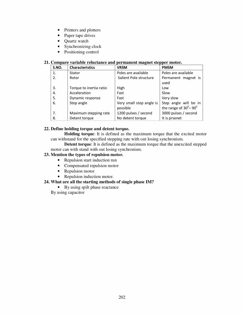
202
• Printers and plotters
• Paper tape drives
• Quartz watch
• Synchronizing clock
• Positioning control
21. Compare variable reluctance and permanent magnet stepper motor. S.NO. Characteristics VRSM PMSM
1.
2.
3.
4.
5.
6.
7.
8.
Stator
Rotor
Torque to inertia ratio
Acceleration
Dynamic response
Step angle
Maximum stepping rate
Detent torque
Poles are available
Salient Pole structure
High
Fast
Fast
Very small step angle is
possible
1200 pulses / second
No detent torque
Poles are available
Permanent magnet is
used
Low
Slow
Very slow
Step angle will be in
the range of 300– 90
0
3000 pulses / second
It is prsenet
22. Define holding torque and detent torque.
Holding torque: It is defined as the maximum torque that the excited motor can withstand for the specified stepping rate with out losing synchronism.
Detent torque: It is defined as the maximum torque that the unexcited stepped motor can with stand with out losing synchronism.
23. Mention the types of repulsion motor.
• Repulsion start induction run
• Compensated repulsion motor
• Repulsion motor
• Repulsion induction motor. 24. What are all the starting methods of single phase IM?
• By using spilt phase reactance By using capacitor