electrical machine ii lab lab manual (ee 327 f) v...
TRANSCRIPT
ELECTRICAL MACHINE II LAB
LAB MANUAL
(EE – 327 – F)
V SEMESTER
DEPARTMENT OF ELECTRICAL & ELECTRONICS
ENGINEERING
DRONACHARYA COLLEGE OF ENGINEERING,
KHENTAWAS, GURGAON – 123506

CONTENTS
Sr.No TITLE Page
No.
1. Study of the No Load and Block Rotor Test in a Three Phase
Slip Ring Induction Motor & draw its circle diagram
2. To perform O.C. test on synchronous generator. And
determine the full load regulation of a three phase
synchronous generator by synchronous impedance method
3. To Study and Measure Direct and Quadrature Axis Reactance
of a 3 phase alternator by Slip Test
4. To Study and Measure Positive, Negative and Zero Sequence
Impedance of a Alternator
5. Synchronization of two Three Phase Alternators, by
a) Synchroscope Method
b) Three dark lamp Method
c) Two bright one dark lamp Method
6. To plot V- Curve of synchronous motor.
7. To Start Induction motor by Rotor resistance starter
8. Regulation of 3-phase alternator by ZPF and ASA methods
9. Star-delta starting of a three phase induction motor
10. Load test on three phase Induction motor

EXPERIMENT NO: 01
AIM:- STUDY OF THE NO LOAD AND BLOCK ROTOR TEST IN A THREE PHASE
SLIP RING INDUCTION MOTOR & DRAW ITS CIRCLE DIAGRAM
APPARATUS:- 3 phase Induction motor with belt and pulley arrangement , three phase supply,
wattmeters , ammeter and voltmeter
FORMLULAE
Coso=Wo / √3 VoIo
Cosr=Wbr / √3 VbrIbr
Ibm = Ibr (Vo/Vbr)
Wbm = Wbr (Vo/Vbr)2
Stator copper loss = 3 Ibr2Rs
PRECAUTION
1. The 3 autotransformer should be kept at initial position.
2. Initially the machine should be under no load condition.
PROCEDURE
NO LOAD TEST
1. Connections are made as per the circuit diagram.
2. 3 AC supply is increased gradually using 3 autotransformer till rated voltage is applied.
3. Readings of voltmeter and wattmeter are noted.
BLOCKED ROTOR TEST
1. Connections are made as per the circuit diagram and rotor is blocked from rotating.
2. Applied voltage is increased until rated load current flows.
3. Readings of all meters are noted.
MEASUREMENT OF STATOR RESISTANCE
1. Connections are made as per the circuit diagram.
2. Supply is given by closing the DPST switch.
3. Readings of voltmeter and ammeter are noted.
4. Stator resistance in ohms is calculated as
Ra/phase = (Vx1.5) /2I
PROCEDURE FOR CONSTRUCTING THE CIRCLE
1. Vector OO’ is drawn at an angle of phase with respect to OY represents the output line.
2. O’X’ is drawn parallel to OX.
3. Vector OA is Ibr plotted at an angle of phasor with respect to OY. O’A is joined which
represents the output line.
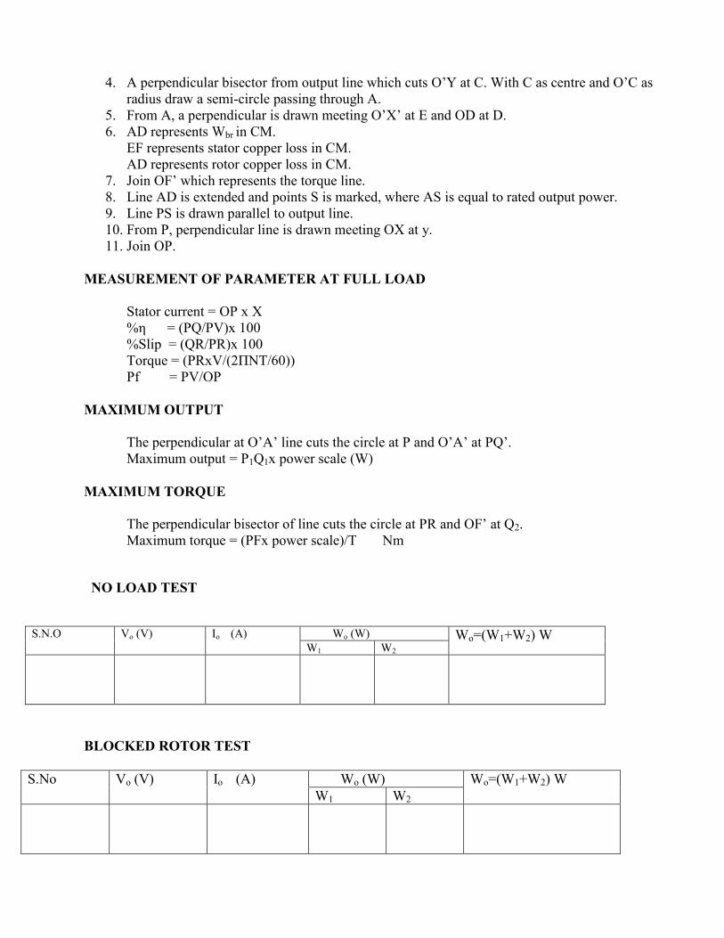
4. A perpendicular bisector from output line which cuts O’Y at C. With C as centre and O’C as
radius draw a semi-circle passing through A.
5. From A, a perpendicular is drawn meeting O’X’ at E and OD at D.
6. AD represents Wbr in CM.
EF represents stator copper loss in CM.
AD represents rotor copper loss in CM.
7. Join OF’ which represents the torque line.
8. Line AD is extended and points S is marked, where AS is equal to rated output power.
9. Line PS is drawn parallel to output line.
10. From P, perpendicular line is drawn meeting OX at y.
11. Join OP.
MEASUREMENT OF PARAMETER AT FULL LOAD
Stator current = OP x X
%η = (PQ/PV)x 100
%Slip = (QR/PR)x 100
Torque = (PRxV/(2ΠNT/60))
Pf = PV/OP
MAXIMUM OUTPUT
The perpendicular at O’A’ line cuts the circle at P and O’A’ at PQ’.
Maximum output = P1Q1x power scale (W)
MAXIMUM TORQUE
The perpendicular bisector of line cuts the circle at PR and OF’ at Q2.
Maximum torque = (PFx power scale)/T Nm
NO LOAD TEST
S.N.O Vo (V) Io (A) Wo (W) Wo=(W1+W2) W
W1 W2
BLOCKED ROTOR TEST
S.No Vo (V) Io (A) Wo (W) Wo=(W1+W2) W
W1 W2

MEASUREMENT OF STATOR RESISTANCE
S.No Voltage (V) Current (A) Rs = (Vx1.5) /2I
PRECAUTION:
1. TPST switch should be at open position.
2. 3-phase autotransformer should be at minimum voltage position.
3. There should be no-load at the time of starting(Loosen the belt on the brake drum)
4. Brake drum should be filled with water.
PROCEDURE:
1. The connections are made as per the circuit diagram.
2. Power supply is obtained from the control panel.
3. The TPST switch is closed.
4. Rated voltage of 3-phase induction motor, is applied by adjusting autotransformer
5. The initial readings of ammeter, voltmeter and wattmeter are noted.
6. By increasing the load step by step, the reading of ammeter, voltmeter and wattmeter
7. Step1 to 6 is repeated till the ammeter shows the rated current of 3-phase induction motor.
8. Decrease the load, bring auto-transformer to its minimum voltage position.
9. Switch off the supply.
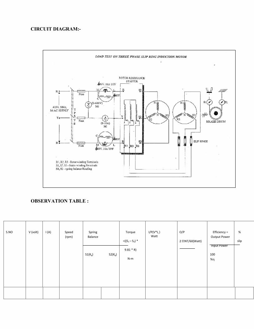
CIRCUIT DIAGRAM:-
OBSERVATION TABLE :
S.NO
V (volt)
I (A)
Speed
(rpm)
Spring
Balance
S1(Kg) S2(Kg)
Torque
=((S1 – S2) *
9.81 * R)
N-m
I/P(V*IL ) Watt
O/P
2 NT/60(Watt)
Efficiency =
Output Power
Input Power
100
%
%
slip

VIVA QUESTIONS :
Explain what is meant by a 3-phase induction motor?
Write the classification of 3-phase induction motor?
State the steps to draw the equivalent circuit of 3-phase induction motor?
State the condition for maximum torque of 3-phase induction motor?
Give the different methods of speed control of I.M.
How do you calculate slip speed?

EXPERIMENT NO: 02
AIM:- TO FIND REGULATION OF A THREE-PHASE ALTERNATOR BY OPEN CIRCUIT
AND SHORT CIRCUIT TESTS
APPARATUS:-
1. Ammeter (0-5A) AC-1No; (0-1A) DC-1 No.
2. Voltmeter (0-300V) AC-1 No.
3. Tachometer - 1 No.
4. Rheostats (400. 1.7A) 1No; 1000. 1.2A 1No.
5. Alternator 3 kVA, 4.2A, 1500 RPM, 3
6. D.C. Motor 3 HP, 220V, 1500RPM
7. Connecting wires etc.
CIRCUIT DIAGRAM:- [A] OPEN CIRCUIT TEST

[B] SHORT CIRCUIT TEST
Neutral
link
Fus
e
L F A
M
220 V
DC
SUPP
LY
220 V
DC
SUPP
LY
A
STATOR
ROTO
R
A

PROCEDURE:
[A] OPEN CIRCUIT TEST
1) Connect the circuit as shown.
2) Set potential divider to zero output position and motor field rheostat to minimum value. 3) Switch on dc supply and start the motor.
4) Adjust motor speed to synchronous value by motor field rheostat and note the meter readings.
5) Increase the field excitation of alternator and note the corresponding readings.
6) Repeat step 5 till 10% above rated terminal voltage of alternator. 7) Maintain constant rotor speed for all readings.
[B] SHORT CIRCUIT TEST
1) Connect the circuit as shown.
2) Star the motor with its field rheostat at minimum resistance position and the potential
divider set to zero output. 3) Adjust the motor speed to synchronous value.
4) Increase the alternator field excitation and note ammeter readings.
5) Repeat step 4for different values of excitations (field current). Take readings up to rated armature current. Maintain constant speed for all readings
6) Measure the value of armature resistance per phase Ra by multimeter or by ammeter-
voltmeter method.
7) Plot the characteristics and find the synchronous impedance.
PRECAUTIONS:
1)All connections should be perfectly tight and no loose wire should lie on the work table.
2)Before switching ON the dc supply , ensure that the starter’s moving arm is at it’s maximum resistance position.
3)Do not switch on the supply, until and unless the connections are checked by the teacher
4)Avoid error due to parallax while reading the meters.
5)Hold the tachometer with both hands steady and in line with the motor shaft so that it reads correctly. 6) Ensure that the winding currents do not exceed their rated values.
OBSERVATIONS:
Alternator armature resistance per phase Ra = ------- Ω Rotor speed = -------------------- RPM
O.C TEST. S.C.TEST
Sr. No
Field current If
(Amp)
Terminal voltage Per phase Vo
Sr. No.
Field current If
Short circuit current Isc

GRAPH: Plot the readings to draw following graphs. Use same graph paper for both curves.
1. If versus Vo(from OC test)
2. If versus Isc (from SC test)
CALCULATIONS:
OA Vo1
Synchronous impedance Zs = ---------- = for field current Isc1
OB Isc1
Isc1 is selected over the linear part of OCC, generally it corresponds to rated armature current.
S.N. Zs Zs (av).
Xs Xs (av). Synchronous reactance Xs = √ (Zs
2 - Ra
2)
Where Ra = Armature resistance of alternator (per phase)
Calculate the excitation emf Eo and voltage regulation for full-load and
1.0.8 lagging p.f. 2. UPF
3.0.8 leading p.f.
Eo = [(V cos + Ia Ra)2 + (V sin + Ia Xs)2]
+ sign is for lagging pf load.
- sign is for leading pf load.
V = rated terminal voltage per phase of alternator
Eo - V %Regulation = ------------ x 100
V
PHASOR DIAGRAMS:
Draw phasor diagrams for above three loads and verify the calculated results.
RESULT: Regulation of alternator at full load is found to be,
At unity pf = --------------
At 0.8 lagging = ---------------
At 0.8 leading = -------------- Synchronous Impedance varies for different values of excitation.

DISCUSSION:
1. Why OCC looks like B-H curve?
2. Why SCC is a straight line?
3. What is armature reaction effect? 4. What are the causes of voltage drop?
5. When is the regulation negative and why?
6. Can we find regulation of a salient pole machine by this test? Justify your answer.

EXPERIMENT NO: -03
AIM: - TO FIND Xd AND Xq OF A SALIENT POLE ROTOR TYPE SYNCHRONOUS MACHINE BY SLIP TEST
APPARATUS:-
1. Alternator ( 3 phase, 1 kw,4.2A, 1500 rpm)
2. DC motor (8A, 220 V, 1500 rpm, shunt) 3. Voltmeter (0-150V) AC.
4. Ammeter (0-5A) A.C
5. Dimmer stat (3 phase, 440 V, 50Hz)
6. Tachometer
CIRCUIT DIAGRAM:-
THEORY:-
The armature reactance varies from Xq to Xd periodically.
Xd - is the synchronous reactance of armature coil offered to the flow of direct axis current.
Xq - is the synchronous reactance of armature coil offered to the flow of quadrature axis
currentWhen voltage induced in the field winding is zero, armature current is minimum and the
terminal voltage is maximum. At this instant direct axis coincides with armature mmf and
corresponding reactance is Xd is given by
Maximum value of armature voltage / phase
Xd = -------------------------------------------------------- Minimum value of armature current / phase
Similarly when the voltage induced in the field winding is maximum ( positive or negative) armature
current is maximum and terminal voltage is minimum. At this instant quadrature axis coincides with
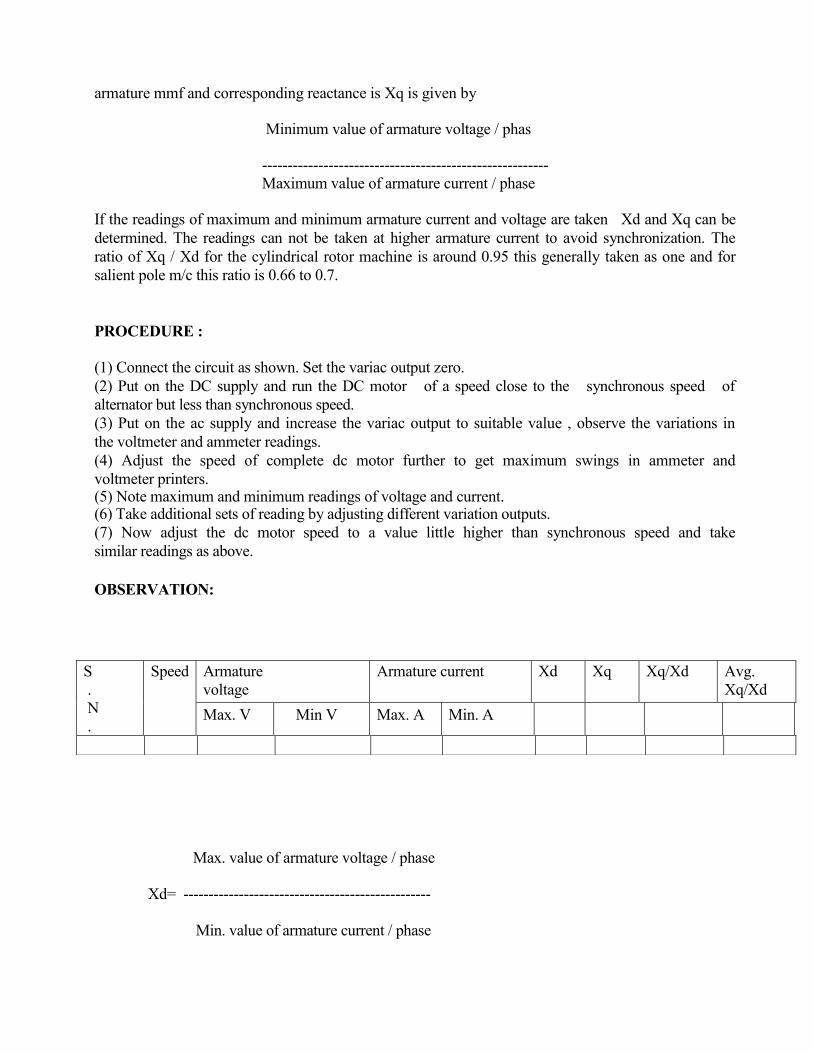
armature mmf and corresponding reactance is Xq is given by
Minimum value of armature voltage / phas
--------------------------------------------------------
Maximum value of armature current / phase
If the readings of maximum and minimum armature current and voltage are taken Xd and Xq can be
determined. The readings can not be taken at higher armature current to avoid synchronization. The
ratio of Xq / Xd for the cylindrical rotor machine is around 0.95 this generally taken as one and for
salient pole m/c this ratio is 0.66 to 0.7.
PROCEDURE :
(1) Connect the circuit as shown. Set the variac output zero.
(2) Put on the DC supply and run the DC motor of a speed close to the synchronous speed of
alternator but less than synchronous speed.
(3) Put on the ac supply and increase the variac output to suitable value , observe the variations in
the voltmeter and ammeter readings.
(4) Adjust the speed of complete dc motor further to get maximum swings in ammeter and
voltmeter printers. (5) Note maximum and minimum readings of voltage and current. (6) Take additional sets of reading by adjusting different variation outputs.
(7) Now adjust the dc motor speed to a value little higher than synchronous speed and take
similar readings as above.
OBSERVATION:
Max. value of armature voltage / phase
Xd= -------------------------------------------------
Min. value of armature current / phase
S
.
N
.
Speed Armature
voltage
Armature current Xd Xq Xq/Xd Avg.
Xq/Xd
Max. V Mn. VM Min V Max. A Min. A

Min. value of armature voltage / phase
Xq= -------------------------------------------------
Max. value of armature current / phase
RESULT :- The ratio of Xq/ Xd is determined for a salient pole rotor type synchronous machine by slip test which is found to be ------------
DISCUSSION QUESTIONS:-
1) Why it is necessary to keep the field open while taking the reading during slip test.
2) Justify that the reactance obtained by O.C. & S.C test is Xd and not Xq.
3) Defined Xd and Xq.
4) What are the normal values of Xq/Xd for the two types of syn. Machines.
5) How will you recognize whether a given syn. machine is cylindrical rotor type or salient
pole type.
6) Why this test is called slip test.
7) Why it is necessary to maintain the slip.
8) What are the main assumptions during this test.

EXPERIMENT NO: - 4
AIM: - DETERMINATION OF NEGATIVE SEQUANCE AND ZERO SEQUENCE
REACTANCE OF A SYNCHRONOUS GENERATOR.
APPARATUS:-
1.Alternator ( 3 phase, 415 V, 4.2A,1500 rpm)
2.DC motor (8A, 215 V, 1500 rpm, shunt)
3.Voltmeter (0-300V, 0-75 V) AC.
4.Ammeter (0-5A) A.C., (0-2 A)DC
5. Dimmer stat (1 phase, 230 V, 50Hz) 6.Wattmeter (150 V, 5A)
CIRCUIT DIAGRAM:-
Negative Sequence

Zero Sequence
THEORY:-
When a synchronous generator is carrying an unbalanced load its operation may be
analyzed by symmetrical components. In a synchronous machine the sequence current produce an
armature reaction which is stationary with respect to reactance and is stationary with respect to
field poles. The component currents therefore encounter exactly same as that by a balanced load as
discussed. The negative sequence is produced and armature reaction which rotates around armature
at synchronous speed in direction to that of field poles and therefore rotates part the field poles at
synchronous speed. Inducing current in the field damper winding and rotor iron. The impendence
encountered by the negative sequence is called the - ve sequence impedance of the generator. The
zero sequence current produce flux in each phase but their combined armature reaction at the air
gap is zero. The impedance encountered by their currents is therefore different from that
encountered by + ve and -ve sequence components and is called zero sequence impedance of
generator.
Negative Sequence Impendence:-
The -ve sequence impedance may be found by applying balanced -ve sequence voltage to the
armature terminals. While the machine is drive by the prime mover at its rated synchronous speed
with the field winding short circuited. The ratio of v/ph and Ia/ph gives -ve sequence Z/ph. The
reading of the wattmeter gives I2 R losses. This loss /ph divided by Iph required gives the -ve
sequence R/ph from the impedance and reactance/ph. -ve sequence can be calculated.
Another method of measuring -ve sequence reactance is found to be connect the arm terminals.
The machine is driven at synchronous speed and field current adjusted until rated current flows in the
phases shorted through armature and current coil of wattmeter respectively
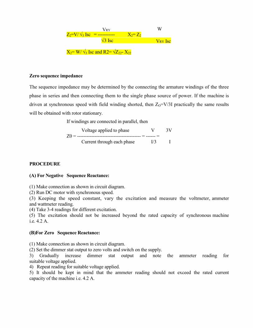
VRY W Z2=V/ 3 Isc = ----------- X2= Z2
3 Isc VRY Isc X2= W/ 3 Isc and R2= Z22- X22
Zero sequence impedance
The sequence impedance may be determined by the connecting the armature windings of the three
phase in series and then connecting them to the single phase source of power. If the machine is
driven at synchronous speed with field winding shorted, then ZO=V/3I practically the same results
will be obtained with rotor stationary.
If windings are connected in parallel, then
Voltage applied to phase V 3V
Z0 = ---------------------------------------- = ------ =
Current through each phase I/3 I
PROCEDURE
(A) For Negative Sequence Reactance:
(1) Make connection as shown in circuit diagram.
(2) Run DC motor with synchronous speed.
(3) Keeping the speed constant, vary the excitation and measure the voltmeter, ammeter
and wattmeter reading. (4) Take 3-4 readings for different excitation.
(5) The excitation should not be increased beyond the rated capacity of synchronous machine
i.e. 4.2 A.
(B)For Zero Sequence Reactance:
(1) Make connection as shown in circuit diagram.
(2) Set the dimmer stat output to zero volts and switch on the supply.
3) Gradually increase dimmer stat output and note the ammeter reading for
suitable voltage applied. 4) Repeat reading for suitable voltage applied.
5) It should be kept in mind that the ammeter reading should not exceed the rated current
capacity of the machine i.e. 4.2 A.
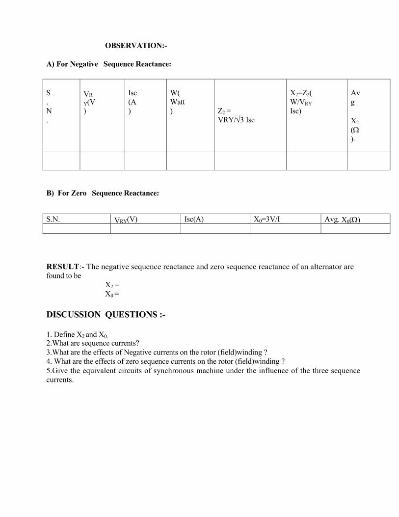
OBSERVATION:-
A) For Negative Sequence Reactance:
B) For Zero Sequence Reactance:
RESULT:- The negative sequence reactance and zero sequence reactance of an alternator are
found to be X2 =
X0 =
DISCUSSION QUESTIONS :-
1. Define X2 and X0.
2.What are sequence currents?
3.What are the effects of Negative currents on the rotor (field)winding ?
4. What are the effects of zero sequence currents on the rotor (field)winding ?
5.Give the equivalent circuits of synchronous machine under the influence of the three sequence
currents.
S
.
N
.
VR
Y(V
)
Isc
(A
)
W(
Watt
)
Z2 =
VRY/3 Isc
X2=Z2(
W/VRY
Isc)
Av
g
X2
(
).
S.N. VRY(V) Isc(A) X0=3V/I Avg. X0()

EXPERIMENT NO: -05
AIM: - TO STUDY THE SYNCHRONIZATION OF ALTERNATOR WITH INFINITE BUS
BY BRIGHT LAMP METHOD.
APPARATUS:-
3 phase alternator: - 1 KW , 4.2A, 1500 rpm , 3 phase , 440 V
DC shunt motor - 1.5 Kw , shunt , 8 A , 220V , 1500 rpm , self excited . Voltmeter 0-600 V AC
Lamp bank, rheostats, 400 ohms - 1.7 A, A knife switches, connecting wires.
CIRCUIT DIAGRAM:-
THEORY:
Following conditions must be satisfied for the synchronization of alternator with infinite
bus. 1) The terminal voltage of the incoming alternator must be equal to the bus voltage.
2) The frequency of incoming alternator must be equal to the bus frequency.
3) The voltage of incoming alternator and bus must be in the same phase with respect to the
external load.
A voltmeter can be used to check the voltage of bus and incoming alternator for frequency and phase lamps are used.
Following are the advantages of parallel operation of alternators.
2) Repairs and maintenance of individual generating unit can be done by keeping the
continuity of supply.
3) Economy 4) Additional sets can be connected in parallel to meet the increasing demand.
PROCEDURE:
1) Connect the circuit as shown in the diagram.
2) Keep all the switches S1, S2, SL1, SL2, and SL3 in open position and put on the DC supply.
3) Start the DC motor and bring the speed very near to synchronous speed of the alternator.
4) Put on AC supply and measure its voltage by keeping the position of switch S2 online side.
5) Now keep the switch S2 on alternator side and adjust its field current such that it
gives voltage equal to the line voltage.
6) Now put on the switches SL1, SL2, SL3 watch the changes in the glow of three
sets of lamps. At one instant two will be equally bright while the third set will be
fully dark. . Then the set which is fully dark slowly starts becoming bright and one
set from the to which were bright starts dimming. A position will come when this set will become
fully dark while other two will be equally bright.
7) Make small adjustment in speed and excitation of alternator to get long dark and bright periods.
8) At an instant when pair IR -IR is dark and IB-IB are equally bright, close switch S-1 to synchronize
the alternator to bus. Observe the reading of ammeter which should be minimum.
RESULT & CONCLUSION:
An alternator can be synchronized with the bus. At the time of synchronization
voltage and frequency of the incoming alternator should be equal to the bus voltage and frequency
and also the voltage of incoming alternator should be in phase with the bus with respect to external
load .
DISCUSSION QUESTIONS:-
1) What are the conditions of synchronization of two alternators?
2) What are the possible effects of wrong synchronization?
3) What are the different methods for synchronization?
4) Why a lamp pair is required in this experiment?
5) After synchronizing what is the effect of changing the excitation of the alternators.
6) Why the incoming m/c in parallel operation is operated at slightly higher speed then the
synchronous speed during synchronization.
7) In parallel operation of generator, for which condition circulating current develop even no load on
the machine.
8) What will happen, if synchronization takes place without proper phase sequence?
EXPERIMENT NO: 06
AIM: - TO PLOT V & INVERTED V CURVES OF A SYNCHRONOUS MOTOR.
APPARATUS:-
1) Synchronous motor 3 Phase, 3 HP, 440V, 8.2A ,1500 rpm,
2) DC shunt Generator 220V, 9A, 1500 rpm
3) Power factor meter-600V, 10A 4) Voltmeter AC- (0-600V), DC- (0-300V)
5) Ammeter AC- (0-10A)
6) Ammeter DC (0-2A), DC (0-10A) 7) Rheostat-470 ohm, 1.2A,
8) Resistive load bank, tachometer, connecting wires, etc.
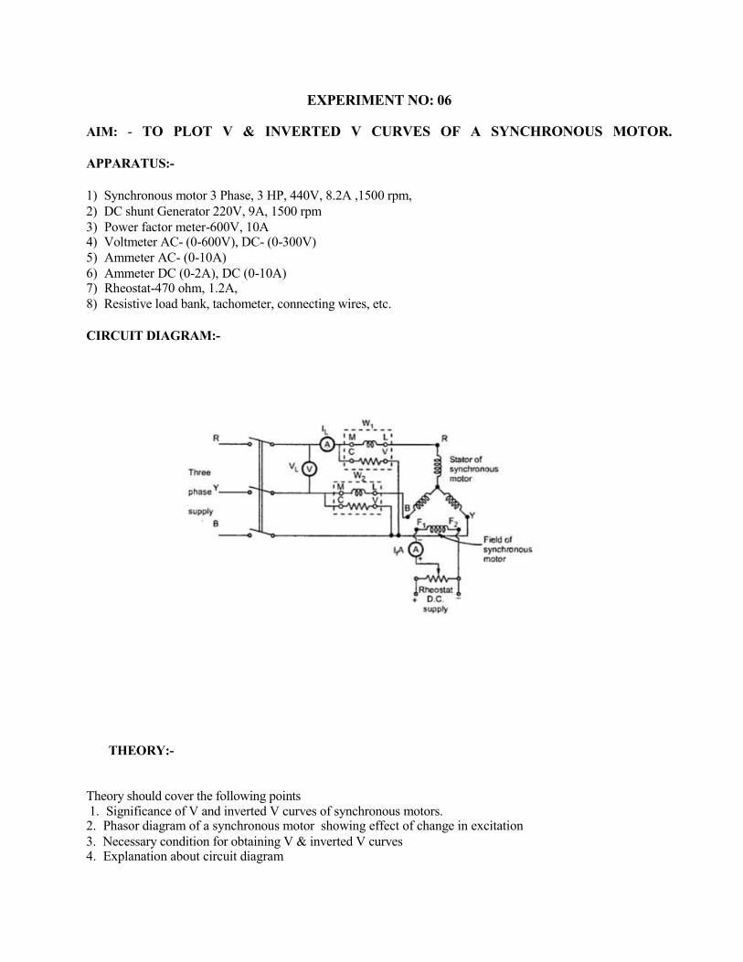
CIRCUIT DIAGRAM:-
THEORY:-
Theory should cover the following points 1. Significance of V and inverted V curves of synchronous motors. 2. Phasor diagram of a synchronous motor showing effect of change in excitation
3. Necessary condition for obtaining V & inverted V curves 4. Explanation about circuit diagram
PROCEDURE:-
1) Make the connections as shown in circuit diagram.
2) Adjust the field rheostat of DC generator at maximum position, the potential divider at zero
output position and the load at off condition. 3) Switch on the 3-ph. supply, start the synchronous motor and let it run at its rated speed.
4) Switch on the DC supply and adjust the generator field current to a suitable value so that it
generates rated voltage.
5) Increase the alternator field current and note down corresponding power factor and armature
current covering a range from low lagging to low leading power factor through a unity power
factor. Note that armature current is minimum when the p.f. in unity. 6) Repeat step No.5 for some constant load on the Generator.
OBSERVATIONS:-
[A] AT NO LOAD
[B] AT LOAD
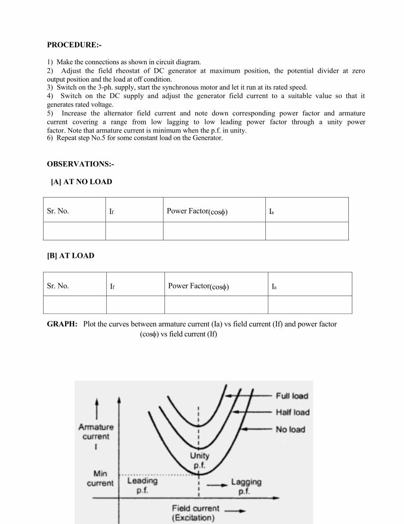
GRAPH: Plot the curves between armature current (Ia) vs field current (If) and power factor
(cos) vs field current (If)
Sr. No. If Power Factor(cos) Ia
Sr. No. If Power Factor(cos) Ia

CONCLUSION:
1. The variation of armature current (line current) and its power factor due to field current variation at load and at no load are shown. The armature current is minimum when the PF is unity.
2. As load increases the V curve shifts upward and the inverted V curve shift towards
right.
DISCUSSION :-
1. With what condition synchronous motor can be used as a synchronous condenser.
2. What are the special applications of an over excited synchronous motor. 3. Explain the effect of change of excitation of a synchronous motor on its armature current.
4. Explain the effect of change of excitation of a synchronous motor on its power factor.
5. With the given excitation a synchronous motor draws a unity PF current . if the mechanical load is increased what will be the power factor and current for the same excitation.
6. Why V curve shift upwards and inverted V curve shift right as the load increases.
7. Explain the effect of change of excitation of a synchronous generator on its armature current. 8. Explain the effect of change of excitation of a synchronous generator on its power factor.

EXPERIMENT NO: 07
AIM: - TO STUDY THE STARTING OF SLIP RING INDUCTION MOTOR BY ROTOR
RESISTANCE STARTER.
APPARATUS:- 1 3-phase slip ring asynchronous motor,1 Magnetic power brake,1 Control unit for brake,1
Rubber Coupling sleeve,1 Coupling guard,1 Shaft end guard,1 Rotation reversing switch,1 Start for slip ring
motors,1 Cut out switch, 3 pole 1 Multimeter,1 Set of connection cables.
THEORY :- Squirrel cage induction motors draw 500% to over 1000% of full load current (FLC) during
starting. While this is not a severe problem for small motors, it is for large (10's of kW) motors. Placing
resistance in series with the rotor windings not only decreases start current, locked rotor current (LRC), but
also increases the starting torque, locked rotor torque (LRT). Figure below shows that by increasing the
rotor resistance from R0 to R1 to R2, the breakdown torque peak is shifted left to zero speed.Note that this
torque peak is much higher than the starting torque available with no rotor resistance (R0) Slip is
proportional to rotor resistance, and pullout torque is proportional to slip. Thus, high torque is produced
while starting.
CIRCUIT DIAGRAM :

OBSERVATION TABLE :-
PROCEDURE :
1. Study the construction and the various parts of the 3-phase induction motor.
2. For rotor resistance starting, connect the slip-ring motor. Start the motor with full starting resistance and
then decrease the resistance in steps down to zero. Take observations of the stator & rotor currents.
3. For direct-on -line starting , connect the cage motor.
4. For star-delta starting , connect the cage motor to the terminals of the star delta.
5. For autotransformer starting, connect the cage motor. Take care at starting that the "Run" switch is open
and that it is not closed before the "Start" switch is opened.
6. In each case observe the starting currents by quickly reading the maximum indication of the ammeters in
the stator circuit.
7. Reverse the direction of rotation of the motor by reversing of two phases at the terminal box. The reversal
has to be made when the motor is stopped and the supply switched off.
Starter
I(A)

EXPERIMENT : 8
AIM : REGULATION OF 3-PHASE ALTERNATOR BY POTIER AND ASA METHODS
APPARATUS REQUIRED
Alternator set up ammeter, voltmeter, Rheostat
CIRCUIT DIAGRAM:
FORMULAE USED:
Percentage regulation = Eo – Vrated x 100 (For both POTIER & ASA methods)
Vrated

OBSERVATION TABLE:

PRECAUTION:
(i) The motor field rheostat should be kept in the minimum resistance position.
(ii) The Alternator field potential divider should be in the position of minimum potential.
(iii) Initially all switches are in open position.
PROCEDURE FOR BOTH POTIER AND ASA METHODS:
1. Note down the complete nameplate details of motor and alternator.
2. Connections are made as per the circuit diagram.
3. Switch on the supply by closing the DPST main switch.
4. Using the Three point starter, start the motor to run at the synchronous speed by varying the motor field
rheostat.
5. Conduct an Open Circuit Test by varying the Potential Divider for various values of Field current and
tabulate the corresponding Open circuit voltage readings.
6. Conduct a Short Circuit Test by closing the TPST knife switch and adjust the potential divider the set the
rated Armature current, tabulate the corresponding Field current.
7. Conduct a ZPF test by adjusting the potential divider for full load current passing through either an
inductive or capacitive load with zero power and tabulate the readings.
8. Conduct a Stator Resistance Test by giving connection as per the circuit diagram and tabulate the voltage
and Current readings for various resistive loads.
PROCEDURE TO DRAW THE POTIER TRIANGLE (ZPF METHOD):
(All the quantities are in per phase value)
1. Draw the Open Circuit Characteristics (Generated Voltage per phase VS Field Current)
2. Mark the point A at X-axis, which is obtained from short circuit test with full load armature current.
3. From the ZPF test, mark the point B for the field current to the corresponding rated armature current and
the rated voltage.
4. Draw the ZPF curve which passing through the point A and B in such a way parallel to the open circuit
characteristics curve.
5. Draw the tangent for the OCC curve from the origin (i.e.) air gap line.
6. Draw the line BC from B towards Y-axis, which is parallel and equal to OA.
7. Draw the parallel line for the tangent from C to the OCC curve.
8. Join the points B and D also drop the perpendicular line DE to BC, where the line DE represents armature
leakage reactance drop (IXL)
BE represents armature reaction excitation (Ifa).
PROCEDURE TO DRAW THE VECTOR DIAGRAM (ZPF METHOD)
1. Select the suitable voltage and current scale.
2. For the corresponding power angle ( Lag, Lead, Unity) draw the voltage vector and current vector OB.
3. Draw the vector AC with the magnitude of IRa drop, which should be parallel to the vector OB.
4. Draw the perpendicular CD to AC from the point C with the magnitude of IXL drop.
5. Join the points O and D, which will be equal to the air gap voltage (Eair).
6. Find out the field current (Ifc) for the corresponding air gap voltage (Eair) from the OCC curve.
7. Draw the vector OF with the magnitude of Ifc which should be perpendicular to the vector OD.
8. Draw the vector FG from F with the magnitude Ifa in such a way it is parallel to the current vector OB.
9. Join the points O and G, which will be equal to the field excitation current (If).
10. Draw the perpendicular line to the vector OG from the point O and extend CD in such a manner to
intersect the perpendicular line at the point H.
11. Find out the open circuit voltage (Eo) for the corresponding field excitation current (If) from the OCC
curve.

12. Find out the regulation from the suitable formula.
PROCEDURE TO DRAW THE POTIER TRIANGLE (ASA METHOD):
(All the quantities are in per phase value)
1. Draw the Open Circuit Characteristics (Generated Voltage per phase VS Field Current)
2. Mark the point A at X-axis, which is obtained from short circuit test with full load armature current.
3. From the ZPF test, mark the point B for the field current to the corresponding rated armature current and
the rated voltage.
4. Draw the ZPF curve which passing through the point A and B in such a way parallel to the open circuit
characteristics curve.
5. Draw the tangent for the OCC curve from the origin (i.e.) air gap line.
6. Draw the line BC from B towards Y-axis, which is parallel and equal to OA.
7. Draw the parallel line for the tangent from C to the OCC curve.
8. Join the points B and D also drop the perpendicular line DE to BC, where the line DE represents armature
leakage reactance drop (IXL)
BE represents armature reaction excitation (Ifa).
9. Extend the line BC towards the Y-axis up to the point O’. The same line intersects the air gap line at point
G.
10. Mark the point I in Y-axis with the magnitude of Eair and draw the line from I towards OCC curve
which should be parallel to X-axis. Let this line cut the air gap line at point H and the OCC curve at point F.
11. Mention the length O’G, HF and OA.
PROCEDURE TO DRAW THE VECTOR DIAGRAM (ASA METHOD)
(To find the field Excitation current If)
1. Draw the vector with the magnitude O’G.
2. From G draw a vector with the magnitude of GH (OA) in such a way to make an angle of (90 ± Φ) from
the line O’G [ (90 + Φ) for lagging power factor and (90 – Φ) for leading power factor]
3. Join the points O’ and, H also extend the vector O’F with the magnitude HF. Where O’F is the field
excitation current (If).
4. Find out the open circuit voltage (Eo) for the corresponding field excitation current (If) from the OCC
curve.
5. Find out the regulation from the suitable formula.
RESULT:
Thus the regulation of 3-phase alternator has been predetermined by the Potier and ASA methods.
VIVA QUESTIONS:
1. What is meant by ZPF Test?
2. What is Potier reactance? How is it determined by Potier triangle?
3. What is meant by armature reaction reactance?
4. What is the significance of the ASA modification of MMF method?
5. What is air gap line in Potier method?

EXPERIMENT - 9
AIM: Star-delta starting of a three phase induction motor
APPARATUS: Three phase induction motor,star delta starter.
THEORY:
NEED FOR STARTER:
At the standstill the motor behaves as the short circuit secondary transformer and it draws heavy current from mains,
which can cause the damages at the starting. It can cause the heavy drops in power line. So direct online starting of
motor is not desirable. The motor has to be started at reduced voltage. For heavy duty motors some starting methods
are used or resistance has to be included in the circuit at starting.
CIRCUIT DIAGRAM:
PROCEDURE:
Star Delta method of starting:
All the six terminals of stator winding are brought out and are connected as shown in Fig. In the starting the stator
winding is connected in start and full voltage is applied across these terminals. The voltage of each phase is 1/3 of
normal value. As the motor picks up the speed, the change over switch disconnects the winding of motor. Now it
connects the winding in delta across supply terminals.
B
A1
DELTA
B1
C2
CONTACTOR
ROTOR
DELTA
A1 C1
R
A2
A2
STATOR
C2
C1
SUPPLY
B1
B2
Y
STAR
3fi AC
STAR
B2
This method reduces the current taken by the motor to one third the current it would have drawn if it was directly
connected in delta. However, the starting Torque is also reduced to one third. This method is cheap, but it should be
used when high starting torque is not required like machine tools, pumps, motor generator etc.
DISCUSSION:
Star Delta method is a safe method for starting of induction motor as the inrush current in the starting is very high
without the starter.This is due to the absence of back emf at the starting.
PRECAUTIONS:
1. Make sure that all connections are tight.
2. The connections should be according to circuit diagram.
3. Don’t touch the naked connection ,it may give shock.

EXPERIMENT : 10
AIM : Load Test on three phase Induction Motor
APPARATUS REQUIRED : Ammeter, Voltmeter, Wattmeter, Tachometer
CIRCUIT DIAGRAM :
THEORY: Slip ring induction motor is also called as phase wound motor. The motor is wound for as many
poles as the no. of stator poles and always wound 3-Ф even while the stator is wound two-phase. The other
three windings are brought out and connected to three insulated slip-rings mounted on the shaft with brushes
resting on them. These three brushes are further externally connected to a three phase star connected
rheostat. This makes possible the introduction of an additional resistance in the rotor circuit during starting
period for increasing starting torque of the motor.

OBSERVATION TABLE :
FORMULAE USED:
1. Torque= (S1-S2)*9.81*100 N-m
2. O/P Power= 2πNT/60 watts
3. I /P Power = (W1+W2) watts
4. η % = (o/p power/ i/p power)*100

5. %s = (Ns-N)/Ns*100
PRECAUTIONS:
1. TPST switch is kept open initially.
2. The external resistance in the rotor circuit should be kept at max. value.