electrical installation and construction standards the approved itp. the following electrical tests...
TRANSCRIPT

Electrical Installation and
Construction Standards
Technical Specification


Contents
1 Introduction .................................................................................................. 6
2 General Requirements ................................................................................ 7
3 Design ......................................................................................................... 8
4 Inspection, Testing & Commissioning ........................................................ 10
4.1 Inspection & Test Plan (ITP) ............................................................ 10
4.2 Factory Acceptance Testing (FAT) .................................................. 10
4.3 Site Acceptance Testing (SAT) ........................................................ 10
4.4 Performance Testing ........................................................................ 12
4.5 Asset Information Recording ............................................................ 12
4.6 Drawings, Manuals & Training ......................................................... 13
4.7 Preferred Suppliers List.................................................................... 13
5 Standards, Codes & Regulations ............................................................... 14
5.1 Standards ......................................................................................... 14
6 Electrical Supply ........................................................................................ 17
6.1 Metering ........................................................................................... 17
6.2 Solar Installations ............................................................................. 17
7 Switchboards & Enclosures ....................................................................... 18
7.1 Construction ..................................................................................... 18
7.2 Mounting & Installation ..................................................................... 20
7.3 Cooling & Heating ............................................................................ 20
7.4 Degree of Protection ........................................................................ 21
7.5 Form of Protection ........................................................................... 21
7.6 Cable Entry ...................................................................................... 21
7.7 Cable Zones ..................................................................................... 21
7.8 Doors ............................................................................................... 21
7.9 Switches ........................................................................................... 22
7.10 Pushbuttons ..................................................................................... 22
7.11 Indicators ......................................................................................... 23
7.12 Equipment Mounting ........................................................................ 23
7.13 Power Distribution ............................................................................ 23
7.14 Control Circuits ................................................................................ 28
7.15 Motor Protection ............................................................................... 31
7.16 Internal Wiring .................................................................................. 31
8 Instrumentation & Field Devices ................................................................ 35
8.1 Flow Meters ..................................................................................... 35
8.2 Level Sensors .................................................................................. 36

8.3 Pressure Sensors ............................................................................. 36
8.4 Flow, Level, Pressure, Limit & Proximity Switches ........................... 36
9 Site Wiring & Installation ............................................................................ 38
9.1 Earthing ............................................................................................ 38
9.2 Cabling ............................................................................................. 38
9.3 Cable Routes .................................................................................... 42
9.4 Conduits ........................................................................................... 43
9.5 Cable Tray & Ladder ........................................................................ 45
9.6 Junction Boxes ................................................................................. 45
9.7 Lighting & General Purpose Power .................................................. 45
10 PLC, HMI, SCADA & Telemetry ................................................................. 47
10.1 Human Machine Interfaces ............................................................... 47
10.2 Alarm Diallers ................................................................................... 47
10.3 Programmable Logic Controllers & Remote Telemetry Units ........... 47
10.4 Remote SCADA ............................................................................... 48
11 Communications ........................................................................................ 49
11.1 Local ................................................................................................. 49
11.2 Landline ............................................................................................ 49
11.3 3G/4G Networks ............................................................................... 49
11.4 Radio ................................................................................................ 49
12 Process & Functional Specification ............................................................ 51
12.1 General............................................................................................. 51
12.2 General Requirements ..................................................................... 51
12.3 Duty / Standby Systems ................................................................... 53
12.4 Programing and Software ................................................................. 53
12.5 Communications ............................................................................... 54
12.6 Software and Licensing .................................................................... 54
12.7 Remote Access and Support ............................................................ 54

Document Status
Rev No
Comments Issue Date
Prepared By Reviewed By
Approved By
1 Initial Draft 18/11/2016 C. Pancutt
2 Reviewed by SGW
21/11/2016 C. Pancutt SGW
3
4
6 | South Gippsland Water – Electrical Standards Specification
1 Introduction
This specification details the general requirements for the design, manufacture, supply, installation, testing, commissioning and documentation of South Gippsland Water (SGW) electrical installations.

South Gippsland Water – Document Title | 7
2 General Requirements
The contractor shall prepare and submit all relevant design drawings and documentation for review and approval by SGW. Written approval must be received from SGW prior to the acquisition of any materials or the commencement of any works by the contractor. SGW shall also nominate a representative to liaise with the contractor for the duration of the works. All equipment shall be supplied new and without modification and installed as per the manufacturer’s specifications. Supplied equipment shall be selected from the SGW Preferred Electrical Equipment Technical Specification, or alternatively, similar equivalent equipment can be supplied with prior approval from SGW Maintenance Manager. Once installed, all equipment shall be easily and safely accessible for operation and maintenance and shall be fully capable of operating under the climatic and environmental conditions in which it is installed. All equipment, connections and cabling shall be designed and arranged to minimise the risk of fire or any damage that may arise in the event of a fire. All aspects of the installation shall include a minimum of 30% spare capacity for future expansion. This shall include, but is not limited to, physical enclosure space, internal ducts, power supply capacity, controller I/O capacity, conduit capacity and cable cores. Practical completion will not be issued until all works, including all documentation and testing information, is fully completed, witnessed and written approval has been issued by SGW.

8 | South Gippsland Water – Electrical Standards Specification
3 Design
The contractor shall prepare a complete and fully detailed electrical design for review and approval by SGW which shall include the following electrical documents as a minimum:
• Drawing Register
• Process and Instrumentation Diagrams
• Site, Lighting and Cable / Conduit Layouts
• Single Line Diagrams
• Electrical Power Schematic Drawings
• Electrical Control Schematic Drawings
• Electrical I/O Schematic Drawings
• General Arrangement Drawings
• Enclosure, Compartment & Gear Tray Layout Drawings
• Equipment Schedules
• Maximum Demand / Fault Analysis Calculations
• Cable Schedule and Sizing Calculations
• Earthing Details and Sizing Calculations
• Inspection & Test Plans / Checklists
If the contractor is responsible for any programming work then the following software documents shall be provided as a minimum:
• Functional Description / Control Philosophy
• Human Machine Interface Design
• I/O Schedule
• Process Control Logic
• Alarm List
• Communication Tables
• Network Topography
• Inspection & Test Plans / Checklists
The contractor shall prepare and submit a project plan detailing the schedule of works. All documents are subject to review while acceptance of designs and approval to manufacture shall only be issued in writing by SGW. Acceptance by SGW of any drawings, method of work or any information regarding materials and equipment the contractor proposes to furnish shall not relieve the contractor of their responsibility for any errors or omissions therein, and shall not be regarded as an assumption of risks or liability. The contractor shall have no claim under the contract on account of the failure, partial failure or inefficiency of any plan or method of work or materials and equipment so accepted.

South Gippsland Water – Document Title | 9
Such acceptance shall be considered to mean that SGW has no objection to the contractor using, upon their own full responsibility, the plan or methods of work proposed or furnishing the materials and equipment proposed. Acceptance of the contractor’s drawings shall not relieve the contractor of their full responsibility to comply with the requirements of the contract drawings and specification.

10 | South Gippsland Water – Electrical Standards Specification
4 Inspection, Testing & Commissioning
4.1 Inspection & Test Plan (ITP)
The contractor shall develop an ITP during the design process which details all tests and procedures to be completed and includes plans for Factory Acceptance Testing, Site Acceptance Testing and Performance Testing as a minimum. The ITP shall be submitted to SGW during the design process with no testing to commence until the ITP is approved in writing by SGW. All tests must be witnessed and signed off by an SGW representative.
4.2 Factory Acceptance Testing (FAT)
Prior to delivery of equipment to site, all equipment shall be tested in accordance with the approved ITP. The following electrical tests and documentation shall be included as a minimum:
• Visual inspection for construction, finish and standard of work
• Inspection for consistency with design and specifications
• Earth continuity tests on all earth conductors
• Insulation resistance tests on all wiring
• Check of labels and nameplates
• Complete check of wiring and terminations
• Conductivity tests of all busbar joints
• Point-to-point testing of all I/O wiring
• Setting and calibration of all protection, interlocks and instrumentation
• Thermal imaging or ductor tests of all bus-bars and power distribution systems
• Full functional testing of all controls, processes, interlocks & protection circuits
The following software tests and documentation shall be included as a minimum:
• Process Control Logic
• Program List
• Variable List
• Communication Tables
• Full functional testing of all controls, processes, interlocks & protection circuits
Equipment shall not be delivered to site until FAT has been completed, fully documented, witnessed and verified in writing by an SGW representative. All equipment shall be properly packaged and secured for transport and loading. As a minimum all ITP’s for FAT / SAT testing shall meet the SGW FAT/SAT Test Document.
4.3 Site Acceptance Testing (SAT)

South Gippsland Water – Document Title | 11
Following completion of FAT and site installation works, SAT shall be conducted. The following electrical tests and documentation shall be included as a minimum:
• Visual inspection for installation, finish, and standard of work
• Inspection for consistency with designs and specifications
• Earth continuity tests on all earth conductors
• Insulation resistance tests on all wiring
• Optic Fibre cable OTDR tests and documentation on all cores
• Check of labels and nameplates
• Complete check of wiring and terminations including enclosures, switchgear, field cabling and devices.
• Point-to-point testing of all I/O wiring
• Setting and calibration of all protection circuits, interlocks and instrumentation
• Thermal imaging tests of all bus-bars and power distribution systems
• Testing of all emergency stops, limit switches and safety devices
• Functional testing of all I/O
• Rotation checks for all pumps and motors
• Position checks for all actuators and valves
• Full functional testing of all controls, processes, interlocks & protection circuits
• All equipment test certificates
• Telemetry Radio Path tests and documentation of fade margin details
• Instrument Calibration Sheets
• Full functional testing of local Human Machine Interfaces
• Conduit Locations and Cross Sections
• Site Layouts showing all Underground Services
• Operation and Maintenance Manuals
The following software tests and documentation shall be included as a minimum:
• Full functional testing of local Human Machine Interfaces
• Complete testing of all alarms
• Full functional testing of all controls, processes, interlocks & protection circuits
• Telemetry checks
• Process Control Logic
• Communication Tables
• Variable List with default values
• Operation and Maintenance Manuals
At the completion of testing, a complete list of all settings applied to each item of equipment and instrumentation, and all software and applications shall be

12 | South Gippsland Water – Electrical Standards Specification
provided to SGW including all authentication and registration information. This shall include all factory default settings and site specific parameters. Signed Certificates of Electrical Safety shall be submitted to the SGW representative on satisfactory completion of any work associated with the connection, or modification of AC power supplies.
4.4 Performance Testing
Upon the completion of all testing and the receipt of all documentation fully completed and consistent with completed works, the installation will be placed into service and a Performance Testing period will commence. The contractor shall guarantee the complete installation including full functionality and rectify / replace all defective equipment promptly and efficiently during construction, testing and the full defects liability period.
4.5 Asset Information Recording
The contractor shall be issued with SGW standard Asset Information forms to record all instrument and equipment details which shall be submitted with final project documentation. These forms shall form part requirement for gaining project practical completion.

South Gippsland Water – Document Title | 13
4.6 Drawings, Manuals & Training
Upon completion of the contract works, the contractor shall update all the design drawings to include all variations and amendments. Soft (AutoCAD) and hard (A3) copies of all final “As Built” drawings shall be supplied to SGW within two (2) weeks of site commissioning. An additional site hard copy (A3) of each drawing, laminated in clear plastic, shall be provided to SGW for storage onsite. Soft (MS Word) and hard (A4) copies of Operation and Maintenance Manuals for all items of electrical equipment and instrumentation shall be provided by the contractor to SGW within two (2) weeks of site commissioning. The manuals shall have hard covers and include the following as a minimum:
sufficient detail to allow SGW to normally service, maintain and operate the plant
a full list of all configuration parameters including site specific and manufacturer default settings, motor drive settings and any passwords
HMI / SCADA / PLC / RTU programs and software
maintenance schedules
ordering codes for spare parts items
Instrument Calibration Sheets, Test Certificates and Data Sheets
training records
The contractor shall conduct training sessions for operational and maintenance personnel utilising the prepared manuals. Practical completion shall not be deemed to have occurred until the final version of operations and maintenance manuals have been received and accepted by SGW.
4.7 Preferred Suppliers List
All electrical equipment shall be installed as per manufacturer’s specifications and shall be capable of operating under climatic and environmental conditions for the location in which it is installed. All items shall be readily and safely accessible for testing, maintenance and replacement. Standard items shall be used that can be replaced from equipment supplied from the manufacturer without modification. All equipment shall be new and of current model and manufacture. The contractor shall refer to the Technical Specification for preferred equipment used by SGW.

14 | South Gippsland Water – Electrical Standards Specification
5 Standards, Codes & Regulations
5.1 Standards
All electrical work implemented shall be in accordance with the current SAA Wiring Rules (AS/NZS 3000), the current Victorian Service & Installation Rules (SIR), the relevant Australian Standards and other applicable Statutory Authority regulations, the requirements of this Specification and relevant Drawings, and the requirements of SGW. Work on, and installation of all electrical equipment and cabling shall comply with, but is not limited to, the following standards:
• AS/NZS 1125 Conductors in Insulated Electric Cables and Flexible Cords
• AS/NZS 1574 Copper and Copper Alloys - Wire For Electrical Purposes
• AS/NZS 1627 Metal Finishing - Preparation and Pre-treatment of Surfaces - Method Selection Guide
• AS/NZS 1660 Test Methods for Electric Cables, Cords and Conductors - Conductors and Metallic Components
• AS/NZS 1680 Interior Lighting
• AS/NZS 1746 Conductors - Bare overhead - Hard-drawn copper
• AS/NZS 1768 Lightning Protection
• AS/NZS 2053 Conduits and fittings for electrical installations
• AS/NZS 2184 Low Voltage Switchgear & Controlgear - Moulded-Case Circuit-Breakers for Rated Voltages up to and including 600 VAC & 250 VDC
• AS/NZS 2381.1 Electrical equipment for explosive gas atmospheres - Selection, installation and maintenance - General requirements
• AS/NZS 2467 Maintenance of electrical switchgear
• AS/NZS 2700 Colour standards for general purpose
• AS/NZS 3000 Electrical Installations (Wiring Rules)
• AS/NZS 3008 Electrical installations – Selection of Cables
• AS/NZS 3010 Electrical Installations – Generating Sets
• AS/NZS 3012 Electrical Installations – Construction and Demolition Sites
• AS/NZS 3017 Electrical Installations – Testing and Inspection Guidelines
• AS/NZS 3080 Information technology - Generic cabling for customer premises
• AS/NZS 3100 Approval and test specification - General Requirements for Electrical Equipment
• AS/NZS 3111 Approval and test specification - Miniature Overcurrent Circuit-Breakers

South Gippsland Water – Document Title | 15
• AS/NZS 3112 Approval and test specification - Plugs and socket-outlets
• AS/NZS 3123 Approval and test specification - Plugs, socket-outlets and couplers for general industrial application
• AS/NZS 3190 Approval and test specification - Residual current devices (current- operated earth-leakage devices)
• AS/NZS 3191 Electric Flexible Cords
• AS/NZS 3439 Low Voltage Switchgear and Controlgear Assemblies
• AS/NZS 3715 Metal finishing - Thermoset powder coating for architectural applications of aluminium and aluminium alloys
• AS/NZS 3768 Guide to the effects of temperature on electrical equipment
• AS/NZS 3947 Low-Voltage Switchgear and Controlgear
• AS/NZS 4009 Software reviews and audits
• AS/NZS 4836 Safe Working on Low Voltage Electrical Installations & Equipment
• AS/NZS 5000 Electric cables - Polymeric insulated
• AS/NZS 60044.1 Instrument transformers – Current transformers
• AS/NZS 60044.2 Instrument transformers – Inductive voltage transformers
• AS/NZS 60079.10 Explosive Atmospheres – Classification of Areas – Explosive Gas Atmospheres
• AS/NZS 60079.14 Explosive Atmospheres – Electrical Installations Design, Selection and Erection
• AS/NZS 60204.1 Safety of Machinery – Electrical Equipment of Machines
• AS/NZS 60269 Low Voltage Fuses
• AS/NZS 60890 A method of temperature-rise assessment by extrapolation for partially type-tested assemblies (PTTA) of low-voltage switchgear and controlgear
• AS/NZS 60947 Low Voltage Switchgear and Controlgear
• AS/NZS 61000 Electromagnetic compatibility (EMC)
• AS/NZS 61131 Programmable controllers
• AS/NZS 61800 Adjustable Speed Electrical Power Drive Systems
• AS/NZS 62061 Safety of Machinery – Functional Safety of Safety-Related Electrical, Electronic & Programmable Electronic Control Systems
• AS/NZS CISPR11 Limits and methods of measurement of electromagnetic disturbance characteristics of industrial, scientific & medical (ISM) radio equipment
• Service and Installation Rules for the relevant Power Supply Authority
• Victorian Electrical Safety Act 1998
• Industry Standard for Electrical Installations on Construction Sites

16 | South Gippsland Water – Electrical Standards Specification
Where a Standard or Code is not nominated the plant shall comply with the relevant Australian, British or other existing Standard, in this order of priority, and shall be subject to the approval of SGW.

South Gippsland Water – Document Title | 17
6 Electrical Supply
The Electrical Supply will be a 3 phase 415 VAC 50Hz MEN system. All work shall conform to requirements of the relevant Power Supply Authority and any other Statutory Authority. The contractor shall be responsible for liaison with the Power Supply Authority and lodgement of an Electrical Work Request (EWR) for isolation/restoration of power supply to the site where required. The contractor shall also be responsible for obtaining all necessary permits and arranging for all inspections and tests of the installation to meet the requirements of the Power Supply Authority, including payment of any associated fees. Any changes or modifications requested by the Power Supply Authority inspectors shall be undertaken by the contractor at the contractor’s expense. Signed Certificates of Electrical Safety shall be submitted to the SGW representative for all work associated with connection of supply to, or modification of, electrical installations. The selection of switchgear and the design of the switchboard enclosure shall take into account the prospective maximum short circuit fault level of the supply to the site. The contractor must ensure that there are no electrical supply issues including normal loading, electromagnetic interference and total harmonic disturbance. Loads shall be equally balanced across all phases of the installation.
6.1 Metering
If metering is required and the site is not already metered, a metering compartment shall be provided as part of the switchboard enclosure. The contractor shall upgrade metering if required to meet any additional demand from equipment to be installed. The contractor must liaise with the Power Supply Authority to determine all metering requirements. The contractor shall pay all fees and charges on behalf of SGW for the connection of all supplies and metering.
6.2 Solar Installations
Where Solar Powered installations are provided for co-generation, Contractors installation and design shall meet the following standards.
AS 4509 Stand-alone power systems.
AS 4086 Secondary batteries for SPS.
AS/NZS 5033 Installation of photovoltaic (PV) arrays.

18 | South Gippsland Water – Electrical Standards Specification
7 Switchboards & Enclosures
7.1 Construction
7.1.1 General
All enclosures shall be totally enclosed self-supporting metal structures and shall consist of a factory assembled combination of pre-designed modules to provide a fully co-ordinated assembly to meet the requirements of the detail specification. They shall include lift-out gear trays, lift-off hinged inner doors and lift-off hinged outer doors. The standards of construction and performance shall comply with AS/NZS 3439. The contractor shall obtain prospective fault current levels at the point of supply and ensure that the switchboard enclosure is designed to withstand this fault level with an adequate margin of safety. As a minimum, the board shall be rated for 20kA for 1 second. Switchgear connected to the main bus bars shall have a rated short circuit service breaking capacity of at least the fault level. An operator control compartment shall be provided for monitoring and control of all plant operations. The control compartment shall be suitable for access by non-electrical personnel, and exclude access to low voltage isolators and circuit breakers. Access is only available to Extra Low Voltage (ELV) switches, indicators, fault resets, touch panels, displays and instrumentation. Circuit breakers shall be grouped to provide clear separation between voltage types and levels. PLC and Telemetry units shall be installed in a dedicated compartment that only contain ELV equipment. Variable Speed Drives (VSD), Soft Starters, Direct Online (DOL) Starters and other equipment with potential to cause interference shall be installed in separate individual compartments. Enclosures for sewer, sludge or chemical dosing systems shall contain separate connection compartments to provide an effective double barrier against the entry of toxic and hazardous gases to the enclosure via cable conduits. These connection compartments shall be effectively vented. Dimensions of all enclosures shall allow a minimum of 30% spare space for future expansion.
7.1.2 Materials & Welding – Switchboard Enclosures
All enclosures shall be constructed from marine grade aluminium sheet minimum 3mm thick and ground smooth before painting. Sheet metal shall be joined by folding and welding. Outer surfaces and visible inner surfaces shall be smoothly finished by grinding and/or matching. All edges shall be folded to a uniform radius, and all edges shall be turned in or concealed; no sharp or rough edges shall protrude. All joints shall be correctly aligned, mitred, continuously welded, and reinforced where necessary. No bolt heads shall project outside the external surface of the enclosure. Seams in enclosure outer shells shall be avoided wherever possible. Where seams are unavoidable, they shall be fillet welded to prevent ingress of moisture. All welds shall be full fillet welds of neat appearance with all scale and weld spatter removed. Visible welds shall be ground and treated so that they conform in appearance and finish to the component material used.

South Gippsland Water – Document Title | 19
All welds shall be mechanically sound, providing adequate penetration and the weld-head shall be uniform and well formed. The dimensions and strengths of the weld shall be such as to provide adequate strength to the component concerned to enable it to fulfil its normal service functions. Bracing shall be provided on all walls, fascia’s and doors to ensure rigidity. Sheet metal shall be reinforced where threaded for installation of screws. Aluminium gland plates with gas-tight seals shall be provided at the bottom of each enclosure for incoming and outgoing cables. Louvres shall be fitted to any enclosure compartments where heat or gas generating equipment is housed. The louvres shall be fitted with dust filters, to prevent ingress of dust into equipment compartments. No 415V/240V AC equipment (e.g.: voltmeters, ammeters) are mounted on rear of doors or escutcheons. All equipment shall have a minimum IP20 rating for live terminals. All cutout openings within the enclosures shall be fitted with plastic bushes, or the metal edges covered with protective edge trimming. Gear plates shall be provided for mounting of equipment. All fittings shall be stainless steel grade 316 including all hinges and dome nuts. All locks and keying systems shall be in compliance to SGW standards. The Metering Board compartment shall have a Victorian power industry lock to suit the Power Supply Authority requirements. Supply Authority Meter enclosures and Metering CT enclosures shall comply with the relevant clauses in the Victorian Service & Installation Rules. A hinged meter panel shall be provided in the meter enclosure for mounting of the Supply Authority meters. The panel shall also comply with the relevant clauses in the Victorian Service & Installation Rules. The manufacturer shall take all reasonable precautions to prevent electrolytic corrosion between metals of dissimilar electrolytic series. To this end, electrical insulating materials shall be used between dissimilar metals where electrical contact is not necessary.
7.1.3 Materials – General Enclosures
All other enclosures shall be constructed from either marine grade aluminium or Stainless Steel as approved by SGW Maintenance Manager for the installation location. Size shall be suited such that there is 30% additional space available for future use.
7.1.4 Painting & Finishing
All metalwork of the enclosures shall be cleaned of welding slag, corrosion and splatter, grease, or other materials likely to impair the finish. All holes and edges shall be free of burrs. Outdoor enclosures shall be powder coated colourbond “Wilderness Green”. Indoor enclosures shall be powder coated colourbond “Orange”. No brushed aluminium enclosures shall be permitted. All internal surfaces shall be painted including the rear of outer doors, both sides of inner doors and both sides of equipment mounting gear trays. The internal surfaces shall first be hand scoured then degreased and given methylated spirits wash. Next, at least one coat of an epoxy primer and one coat of exterior enamelled paint shall be applied. The paint shall be non-yellowing white in colour.

20 | South Gippsland Water – Electrical Standards Specification
Any paintwork damage during the progress of work or in transport shall be repaired so that no blemish occurs afterwards. The finished paint shall be smooth and uniform in thickness at all places, including edges and projections, and shall be free from sagging, streakiness, floating or other defects. The total dry film thickness of the finished interior paint shall not be less than 0.1mm. The following notices/information shall be fitted to the enclosure as a minimum:
a) Plate providing information relating to the pump sets (serial #s, curve #s, FLC, duty head/flows, setting levels of ultrasonic level controller, diameter and length of rising main.
b) Complete set of wiring diagrams for enclosure to be laminated and fitted to the inside door.
c) An information plate providing the name of site and emergency contact numbers on exterior of door – notice to be made from durable plastic dimension not less than 250mm x 150mm.
d) An information plate giving manufacturers details.
7.2 Mounting & Installation
All enclosures shall be bolted to a plinth base of not less than 75mm height, and shall be of adequate thickness to support the enclosure and securely anchor it to the floor. Outdoor enclosures shall be mounted on a concrete pad with 25mm chamfered edges extending at least 1m in front of the enclosure. The top of the pad shall stand above the finished ground level to eliminate rain fall and other run off. All fasteners should be stainless steel and the bottom of the enclosure should be sealed by mastic edges to prevent water ingress. All enclosures shall be mounted above the 100 year flood level. Enclosures shall not be installed within 7 days after pouring of supporting concrete. Enclosures shall be fitted with a safe and effective lifting arrangement. Outdoor enclosures shall be installed facing away from predominant weather and sun light.
7.3 Cooling & Heating
Enclosures shall be provided with effective and efficient ventilation to provide adequate cooling under all ambient conditions. Ventilation shall ensure the temperature in the enclosure does not exceed ambient temperature by more than 10°C and does not exceed equipment manufacturer’s temperature specifications. Fans shall be controlled by a dedicated thermostat for each enclosure. All air vents shall be provided with removable filters to prevent ingress of dust and insects and maintain the ingress protection rating of the enclosure. Fans shall be mounted to directly extract air from the top of the enclosure. All outdoor enclosures shall be fitted with anti-condensation type heaters operated by a dedicated thermostat. Heaters shall be fitted at the bottom of the enclosure and protected to prevent inadvertent contact with the heater element.

South Gippsland Water – Document Title | 21
7.4 Degree of Protection
For outdoor applications, enclosures shall have an external weatherproof IP65 shell with a sloping rain-hood. For indoor applications, enclosures shall have an external dustproof IP54 shell. All electrical equipment installed in the following areas shall have specified ingress protection ratings:
Area IP Rating Inside Enclosures Absolute Minimum of IP21
Indoors Absolute Minimum of IP42
Outdoors Absolute Minimum of IP65
Buried Absolute Minimum of IP68
Wet Wells Absolute Minimum of IP68
7.5 Form of Protection
All enclosures shall be designed to contain faults and provide safety for personnel in the vicinity in the event of an arcing fault. For enclosures containing motor starters rated 15kW and above, the enclosure shall be of Form 3B as per AS/NZS 3439.1. This will require a separate compartment for each motor starter. For enclosures containing motor starters rated below 15kW, the enclosure shall be of 3BHI (separation by Housing and Insulation) as per AS/NZS 3439.1. This will allow grouping of up to four motor starters in a single compartment. Duty and Standby equipment shall not be contained in the same compartment.
7.6 Cable Entry
All enclosures shall include gland plates for all cable entries. The gland plates shall be sized to allow for 30% future expansion. Cable entries are only permitted in the top or bottom of indoor enclosures. Cable entries are only permitted in the bottom of outdoor enclosures.
7.7 Cable Zones
Fully enclosed vertical cable zones shall be provided on either side of each individual compartment. Cables zones shall have full provisions for the installation and support of cables.
7.8 Doors
7.8.1 General
All doors shall be constructed from marine grade aluminium sheet minimum 3mm thick and ground smooth before painting. Doors shall be pressed or rolled to give a neat rounded finish and shall be lipped all round, minimum lip 20mm with corners mitred and welded. Doors in excess of 600mm high shall be fitted with a stiffening channel of a broad "Top Hat" section with returned edges, spot welded down the centre of the door for its entire length.
22 | South Gippsland Water – Electrical Standards Specification
All doors higher than 1m shall have 3-point latching which shall be of a type designed to exert pressure on the door seal progressively as the door handle is turned to close. Enclosure doors shall be fitted with side mounted lift off chrome plated door hinges with stainless steel pins and, on the outer doors, with chrome plated alloy door handles fitted with cylinder locks. The inner hinged panels shall be fastened with chrome plated, knurled and slotted alloy thumb screws with retaining clips. Both the outer and inner doors shall be fitted with door stays to enable the outer doors to be rigidly held open a minimum of 90 degrees and the inner doors a minimum of 85 degrees. Gas struts shall be fitted to prevent doors being blown open by wind. Doors shall be hinged so that, where access is likely to be required to adjacent enclosures at the same time or, where double doors are fitted to enclosures, the doors shall open away from one another where practicable. All doors shall be fully gasketed with high density neoprene or approved equivalent seals. A channel shall be provided on all sides of the doorframe and shall provide effective water run-off. Escutcheon doors, plates or shrouds are required over all items of equipment requiring access by non-technical personnel for the purpose of switching or circuit breaker operation. Door mounted controls, push buttons and indicators shall be included for all individual items of plant so that each item may be fully operated and observed. All doors with controls mounted shall include a mounting strip on the rear of the door to facilitate securing of equipment. All external Switchboard doors shall be lockable to SGW keyed system. SGW will free issue barrels for installation by the Contractor.
7.9 Switches
Selector switches shall have a rotary action and shall be of the flush mounting type, complete with escutcheon plate engraved with position designations. As a minimum, each device shall have a selector switch labelled ON/OFF/AUTO (or equivalent) to operate the device. Operation of the selector switch shall bypass process interlocks only, safety and thermal interlocks shall remain active at all times. All labels shall be located directly above the switch. All operator controls shall be mounted no lower than 500mm above floor level.
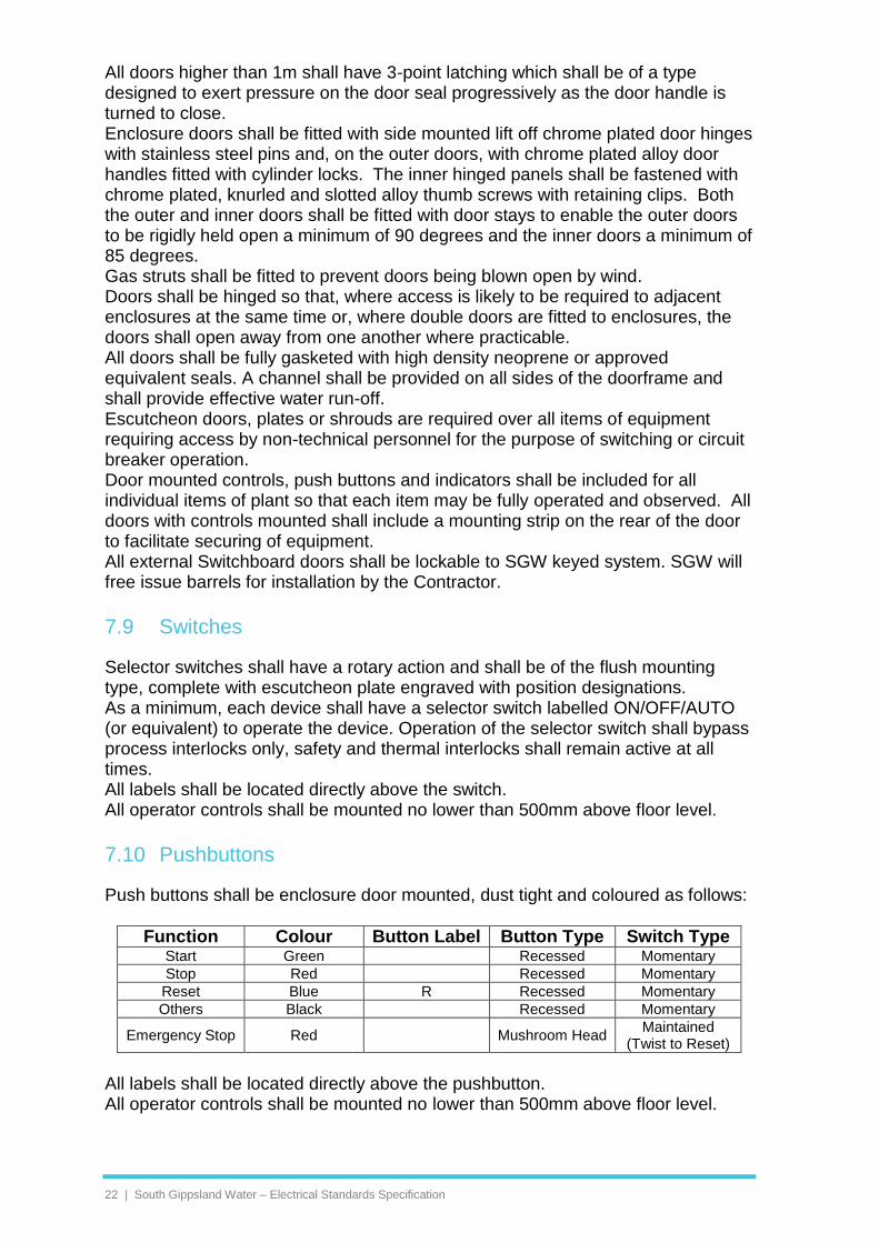
7.10 Pushbuttons
Push buttons shall be enclosure door mounted, dust tight and coloured as follows:
Function Colour Button Label Button Type Switch Type Start Green Recessed Momentary
Stop Red Recessed Momentary
Reset Blue R Recessed Momentary
Others Black Recessed Momentary
Emergency Stop Red Mushroom Head Maintained
(Twist to Reset)
All labels shall be located directly above the pushbutton. All operator controls shall be mounted no lower than 500mm above floor level.
South Gippsland Water – Document Title | 23
7.11 Indicators
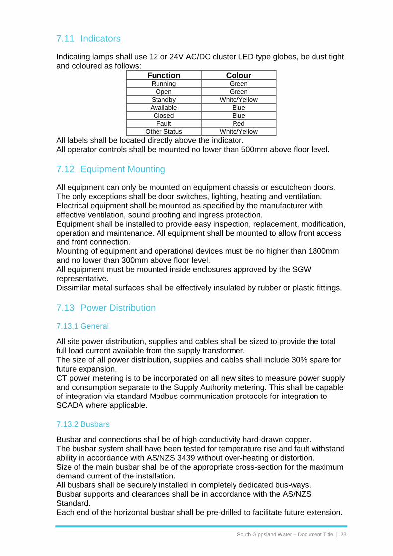
Indicating lamps shall use 12 or 24V AC/DC cluster LED type globes, be dust tight and coloured as follows:
Function Colour Running Green
Open Green
Standby White/Yellow
Available Blue
Closed Blue
Fault Red
Other Status White/Yellow
All labels shall be located directly above the indicator. All operator controls shall be mounted no lower than 500mm above floor level.
7.12 Equipment Mounting
All equipment can only be mounted on equipment chassis or escutcheon doors. The only exceptions shall be door switches, lighting, heating and ventilation. Electrical equipment shall be mounted as specified by the manufacturer with effective ventilation, sound proofing and ingress protection. Equipment shall be installed to provide easy inspection, replacement, modification, operation and maintenance. All equipment shall be mounted to allow front access and front connection. Mounting of equipment and operational devices must be no higher than 1800mm and no lower than 300mm above floor level. All equipment must be mounted inside enclosures approved by the SGW representative. Dissimilar metal surfaces shall be effectively insulated by rubber or plastic fittings.
7.13 Power Distribution
7.13.1 General
All site power distribution, supplies and cables shall be sized to provide the total full load current available from the supply transformer. The size of all power distribution, supplies and cables shall include 30% spare for future expansion. CT power metering is to be incorporated on all new sites to measure power supply and consumption separate to the Supply Authority metering. This shall be capable of integration via standard Modbus communication protocols for integration to SCADA where applicable.
7.13.2 Busbars
Busbar and connections shall be of high conductivity hard-drawn copper. The busbar system shall have been tested for temperature rise and fault withstand ability in accordance with AS/NZS 3439 without over-heating or distortion. Size of the main busbar shall be of the appropriate cross-section for the maximum demand current of the installation. All busbars shall be securely installed in completely dedicated bus-ways. Busbar supports and clearances shall be in accordance with the AS/NZS Standard. Each end of the horizontal busbar shall be pre-drilled to facilitate future extension.
24 | South Gippsland Water – Electrical Standards Specification
Busbar shall be completely insulated in phase coloured insulation as follows: RED-WHITE-BLUE for phases, BLACK for neutral and GREEN/YELLOW for earth. Taping of busbars is not acceptable. Joints in busbars to be draw filed smooth and where holes are drilled they shall be countersunk to remove burrs, all copper jointing faces shall be tinned. Bolts clamping busbars together and studs of equipment connected to busbars shall be fitted with locking washers or securely locknutted, by means of nickel plated metric size nuts and bolts. Connections shall be as close as possible to the base of the stud to minimise leverage due to mechanical stresses under load. Busbar fork is not to be used for connections on MCBs. Generally all enclosures shall be fitted with full size neutral busbars in accordance with AS/NZS 3000 unless otherwise stated elsewhere. An earthing bar shall be supplied and installed in accordance with the requirements of the Power Supply Authority. Earthing and neutral bars shall be drilled to facilitate connection of outgoing circuit cabling and numbered accordingly. Bus clamps are an acceptable alternative. Earthing and neutral bars shall be freely accessible for safe connection or disconnection of circuit conductor while the main bus is energised.
7.13.3 Main Switch Isolator
All Main Switchboard enclosures shall be fitted with a Main Switch Isolator, clearly labelled, to isolate each and every source of power to the installation as per AS/NZS 3000. In the case where the Main Switch Isolator for an alternate power source (such as a generator or UPS) is not installed within the switchboard enclosure a warning label must be clearly displayed stating “ALTERNATE ELECTRICAL SUPPLY ISOLATE ELSEWHERE.”
7.13.4 Generator Changeover Switches
All switchboard enclosures shall be fitted with a manual changeover switch to readily connect a generator to supply the total maximum switchboard load. The switch shall have the following positions: • NORMAL (Power Supply Authority – Mains Supply). • OFF (No Supply Source Connected). • GENERATOR (Emergency Generator Supply). A connection point shall be installed in one side of the switchboard enclosure for the connection of an emergency mobile generator. The connection point shall be enclosed in a suitably rated lockable enclosure with cable access from the bottom. The connection point enclosure shall be lockable with the cable from the generator connected. The connection shall be a reverse 5-pin socket for terminations rated 250A 3-phase or less with bolt and lug for terminations rated higher than 250A 3-phase. SGW shall advise if automatic changeover equipment is required. Any automatic changeover system shall include a bypass to effectively bypass and isolate the automatic changeover equipment. Note: In the case where the Main Switch Isolator for an alternate power source (such as a generator) is not installed within the switchboard enclosure a warning label must be clearly displayed stating “ALTERNATE ELECTRICAL SUPPLY ISOLATE ELSEWHERE.”

South Gippsland Water – Document Title | 25
7.13.5 Combined Fused Switches (CFS)
These shall be provided with ratings as shown in single line diagrams, and be suitable for barrel type fuses. Interlocking and performance shall be in accordance with AS/NZS 3947. Labels shall include the fuse rating and a separate switch rating. SGW’s preference is for use of Circuit Breakers over CFS units, CFS units shall only be used on approval of the SGW Maintenance Manager.
7.13.6 Circuit Breakers
The switchboard enclosure shall be supplied complete with all circuit breakers and ancillaries. Circuit breakers shall be thermal-magnetic type moulded case circuit breakers of appropriate fault level with front connecting terminals and captive clamping plates shrouded by insulated covers. Where circuit breakers are used as isolators they shall be lockable in the open position. D-Curve type Circuit Breakers shall be used for motor starter applications. Multi-pole breakers shall have a common tripping mechanism. All Circuit Breaker functions shall be operable without having to open the compartment inner door. Circuit breakers shall be mounted on brackets, or gear plates, independent of the terminals. A single circuit breaker shall be provided for each individual item of equipment. All spare poles shall be fitted with plastic pole fillers.
7.13.7 Fuses
Fuses for 415V/240V AC circuits shall be of the non-wireable enclosed HRC type, complying to AS/NZS 60269, rated at 415V operation. AC fuse holders shall be front wired and the contacts shall be fully shrouded to avoid accidental contact when fuse carriers are removed. Fuse holders shall be of the DIN-Rail mounting type. The incoming, or “live” side of the AC fuse bases shall be oriented towards the top of the enclosure. Fuses for DC supplies shall be “quick-blow” glass type, suitable for fitment in DIN-Rail mounted fuse terminals.
7.13.8 Isolators
All isolators shall be Load-Break type, clearly marked and lockable in the open position. Isolators shall include mechanical interlocks to prevent access to enclosures without effective isolation. Field isolators shall be included for each motor adjacent to the motor. Field isolators shall include extra terminals to monitor and suppress alarms.
7.13.9 Neutral Links & Earth Bars
A neutral bar and earth bar of either brass or copper shall be provided in each enclosure. Each bar must be able to accommodate all internal and external connections as well as provide spare capacity of at least 30% spare terminals. The

26 | South Gippsland Water – Electrical Standards Specification
earth bar shall be solidly earthed to the enclosure structure, while the neutral bar shall be insulated from earth. All enclosure doors, gland plates, transformer frames, instrument cases, equipment cases, and other exposed metal parts must be connected to the main earth bar by Green/Yellow PVC insulated copper wire of minimum size 2.5mm2. With respect to enclosure internal earthing, all exposed metal parts shall be made effectively earthed. In this aspect, any metal part which is painted or coated with enamel or insulating finish shall not be deemed to be in good electrical contact with the earth bar or other earthed part merely by contact of the coated surface to such part or by through the screws and bolts making contact with such earthed parts, but shall be earthed by means of an identifiable earth conductor connecting it to the earth bar. Separate earth bars shall be provided for Power Earth (Main Earth Bar) and Instrument Earth. The Power Earth Bar shall be located in the Main Switch compartment. All power cable earths, motor earths and 415V/240V AC equipment earths shall be bonded to the Power Earth Bar. MEN connection facilities shall be provided in the Main Switch compartment. The location of the MEN link shall be clearly identified by a label on the compartment door, as required by the Victorian Service & Installation Rules. The Instrument Earth Bar shall be located in the Control compartment. All instrument earths, including instrument equipment frame earths and instrumentation cable screens shall be bonded to the Instrument Earth Bar. Instruments that have metal frames shall be insulated from enclosure mounting plates using non-conductive fixings, to ensure that the Instrumentation earth system is isolated from the Power Earth system.
7.13.10 Surge Protection
Equipment in switchboard enclosures shall be protected by a surge diverter in each phase. All sensitive equipment including PCs, PLCs, telemetry or electronic/instrumentation equipment, shall be further protected by a dedicated surge diverter. The surge diverters shall be covered with a clear plastic shroud to prevent hand contact with live terminals as well as to protect adjacent equipment from damage due to possible catastrophic failure of the surge diverters during a lightning strike. The active terminals of the surge diverters shall be wired to the load terminals of the Main Switch Power Circuit Breaker, via fuses (or MCB), using 16mm2, stranded single core PVC insulated cables. The earth terminals of the diverters shall be bridged together using copper busbar. One 16mm2 stranded PVC insulated Earth conductor shall run from the earth side of the surge diverters, to the Main Earth Bar. The Earth conductor run shall be as straight and as short as possible. The normally open alarm contacts of the surge diverters shall be wired, in parallel, to a dedicated digital input in the PLC / RTU, via terminals. Data signals which interface to Telstra lines shall be protected using Austel compliant line protection devices. Where instrumentation cabling is run external to the switchboard enclosure, each instrument cable loop signal shall be terminated at a transient barrier within the control compartment. Coaxial antenna connections shall be fitted with Coaxial Surge Protectors, selected to suit the requirements of the connected equipment.

South Gippsland Water – Document Title | 27
7.13.11 Power & Phase Failure Relays
Where the power supply to the installation is 3-phase, a dedicated power failure relay shall be installed to detect failure of each phase and phase reversal. The relay shall also provide under and over voltage monitoring and be fully adjustable. Where the power supply to the installation is single-phase, an under voltage relay shall be installed.
7.13.12 Power Transformers
Transformers shall comply with AS/NZS 60044. Double winding shall be incorporated, to separate the primary and secondary windings electrically. A metallic screen shall be incorporated between the primary and secondary windings, to intercept any primary to secondary leakage currents. The screen must be solidly earthed to the enclosure frame earth. The transformer shall be sized to accommodate the full load, plus 30% spare capacity for future load expansion.
7.13.13 DC Power Supplies
All controls (including relays, indicating lamps, solenoids, but excluding motor contactors) shall be powered at 12 or 24VDC using a 240VAC/24VDC Switch Mode Power Supply unless otherwise specified. The DC Power Supply shall be sized to accommodate the full DC load, plus 30% spare capacity for future load expansion. The distribution of DC power to the control and instrumentation circuits shall be by DIN-Rail mounted fused terminal blocks.
7.13.14 Uninterruptable Power Supply (UPS)
Where specified, UPS units shall be provided for critical process and instrumentation equipment. The UPS shall be rated to provide 150% of the process load. UPS’ supplying critical instruments shall be capable of providing supply for a minimum of 6 hours. Each UPS must be supplied with a separate sub-board and circuits, and all UPS circuits shall be appropriately labelled at each supply/termination point. All general purpose outlets supplied from a UPS shall be coloured red. During normal operation, the UPS shall float charge the batteries at a controlled current. In the event of mains failure, the batteries shall provide uninterrupted power to the load. The UPS shall have a battery disconnect feature that protects the batteries from being over-discharged. The UPS shall feature charger and battery alarm contacts and LED indicators to show the operational status of the power supply and battery. Battery terminal connections shall be protected with rubber boots. Batteries shall be located at the base of the control compartment of the enclosure, and shall be held securely in position with retaining brackets, to ensure that the batteries do not dislodge during enclosure transport. The battery charger shall be capable of recharging the batteries within six (6) hours of power supply restoration. A bypass switch shall be incorporated for all UPS units that shall effectively bypass and isolate the UPS. Note: In the case where the Main Switch Isolator for an alternate power source (such as a UPS) is not installed within the switchboard enclosure a warning label must be clearly displayed stating “ALTERNATE ELECTRICAL SUPPLY ISOLATE ELSEWHERE.”

28 | South Gippsland Water – Electrical Standards Specification
7.13.15 Battery Backup
Where specified, battery backup shall be provided for critical process and instrumentation equipment. A minimum 6 hours battery operation is required. Minimum battery size is 17Ahr sealed lead acid battery. The battery shall be suitably thermally insulated to maximise battery life.
7.14 Control Circuits
7.14.1 General
All equipment with potential to cause damage to persons or property shall include emergency stop functionality. This shall include all equipment with moving parts. Emergency stop circuits shall be operated by red mushroom head push buttons wired fail-safe and directly to devices to interrupt power supply to equipment. These shall incorporate a dedicated reset push-button separate to the emergency stop device. All equipment controls shall include an individual fault reset relay that can be operated from a PLC or RTU as well as the local control compartment. There shall also be a master reset for the resetting of the entire control system.
7.14.2 Motor Starters
Motor starters shall comply with AS/NZS 3947.4.1. They shall be suitable for both intermittent duty rating Class 0.1 (12 starts per hour) and uninterrupted duty utilisation category AC-3. Motor starters shall have a mechanical endurance of 3 million cycles. All Soft-Starters and DOL motor starters shall include a current transformer on at least one phase to monitor current. Variable Speed Drive or Soft-Starters shall be fitted for all motors over 5kW. Variable Speed Drives shall be fitted for all motors over 22kW. Starter controls shall operate at 24VAC or 24VDC – with the exception of line contactors, which shall utilise 240VAC coils, to minimise inrush current on the control supply. The 240VAC control for the line contactors shall be switched via auxiliary Circuit Breakers downstream of the Motor Starter Isolating Circuit Breakers. The starters shall be able to re-start automatically after a power cut has been restored (staggered starting for multiple pumps). The types of starters selected for the motors shall be determined by the rating of the motor and its starting currents. The maximum starting currents shall comply with the regulations of the Power Supply Authority. Documentation shall be submitted to show the necessary compliance.
7.14.3 Direct On Line (DOL)
All DOL contactors shall be of the moulded block type construction complying with AS/NZS 3947.4.1 and shall be suitable for DOL starting of 3-phase, 415 VAC motors. Contactors shall be provided with positive ON/OFF status indication, and shall be fitted with auxiliary contacts of rated thermal capacity not less than 10A at 240VAC, plus one spare normally open and one spare normally closed auxiliary contact of similar rating, wired out to terminals.

South Gippsland Water – Document Title | 29
Thermal overload protection shall be provided via circuit breaker add-on module or dedicated protection relay.
7.14.4 Soft Starters
Soft starters shall be able to operate within the tolerance of the voltage and frequency of the incoming electricity supply being 415V, 3 phase, 50 Hz and shall have the following features:
• Start/Stop and Reset digital inputs.
• Volt-free contacts for Fault and Running outputs.
• Built-in bypass contactor.
• Automatic restart after power supply failure.
• Closed loop current control.
• Independent and adjustable linear acceleration ramp start and linear deceleration ramp stop of up to 120 seconds.
• Protection for electronic shear pin, adjustable motor overload, motor over-temperature, phase sequence, phase imbalance, excess starts, undercurrent, shorted SCR.
• Programmable via a remote, enclosure door-mountable operator interface.
• RS485/RS232 serial communications facilities which support standard communications protocols such as DeviceNet, Modbus, Profibus. Industrial Ethernet connectivity shall also be offered.
Adequate ventilation shall be provided for the starter compartment of the enclosure to prevent overheating of the starter module. The operating temperature within the compartment shall be maintained within the manufacturers specified limits. The housing for the starter unit shall prevent radiation of radio frequency interference (RFI). Adequate screening shall be provided for control cables to suppress RFI and avoid signal disturbances to other electronic equipment. The equipment shall comply with AS/NZS 61000.3.6, AS/NZS 61800-3 and AS/NZS CISPR 11 in relation to minimisation of Electromagnetic and Harmonic Interference.
7.14.5 Variable Speed Drives (VSD)
VSD’s shall be selected on the basis of maximum motor full load 'nameplate' amps (+10%) and not the kW or hp rating. VSD’s shall be capable of 110% peak output current without damage or fault. The VSD shall be suitable for continuous full load operation without derating in ambient temperatures of 40°C. Operation up to 50°C shall be possible with derating. Adequate forced-air ventilation shall be provided in each VSD compartment of the enclosure to prevent overheating of the VSD. The operating temperature within the VSD compartment shall be maintained within the manufacturers specified limits. VSD’s shall operate on any supply between 300 and 500VAC, at 48 to 62Hz. The output frequency shall remain constant regardless of load or supply variations, throughout the ambient temperature range of 0°C to 50°C.

30 | South Gippsland Water – Electrical Standards Specification
VSD adjustment shall be made via a remote, enclosure door-mountable operator interface capable of being 'locked' to prevent unauthorised access and modification. The operator interface shall provide programming access and manual control functions. All status, alarm and programming messages shall be displayed in plain English. The Drive Output Frequency (Hz) shall be displayed during normal operation. Manual/Off/Auto control of the VSD shall be achieved via a control selector switch on the control compartment door. When MANUAL control is selected the VSD shall be started via a START pushbutton, and shall ramp the pump up to a preset speed. The VSD shall then be stopped via a STOP pushbutton, and shall slowly ramp down the pump speed and stop the pump When AUTO mode is selected, the local Stop/Start pushbuttons shall be inhibited. Automatic speed control shall be via a “Start/Run” digital input to the VSD and an analog input (4–20mA) to the VSD. The analog inputs shall be suitable for 4–20mA current loop inputs. Configurable output relays shall signal any one of the following conditions as minimum: Available, Running, Fault. The drive shall incorporate RS485/RS232 serial communications facilities which support standard communications protocols such as DeviceNet, Modbus, Profibus. Industrial Ethernet connectivity shall also be offered. The VSD shall be protected against the following conditions as minimum: short circuit, earth fault, cooling fan failure, VSD over-temperature, motor over-temperature, motor overload, under voltage, over voltage. Motor thermal protection shall comprise selectable thermal overload (120% - 200%), microtherm or thermistor trip. The VSD shall accept direct connection to a thermistor or microtherm without the need for interposing relays or other equipment. Local and remote reset facilities shall be provided for resetting of VSD protection faults. The VSD shall be capable of starting into a rotating load in either direction and regain speed control without damage to the controller. Fault trip log shall record the last 10 events as minimum. Automatic restart shall be selectable, with programmable reset time and restart attempts. Acceleration and deceleration shall be independently adjustable over the range of 0.5 to 600s. The VSD shall include comprehensive internal PI and PID control loop for direct sensor connection. Adequate ventilation shall be provided for the VSD compartment of the enclosure to prevent overheating of the VSD. The operating temperature within the compartment shall be maintained within the manufacturers specified limits. The housing for the VSD shall prevent radiation of radio frequency interference (RFI). Adequate screening shall be provided for control cables to suppress RFI and avoid signal disturbances to other electronic equipment. All VSDs shall include harmonic filters. The equipment shall comply with AS/NZS 61000.3.6, AS/NZS 61800-3 and AS/NZS CISPR 11 in relation to minimisation of Electromagnetic and Harmonic Interference.

South Gippsland Water – Document Title | 31
7.15 Motor Protection
All motors shall be protected by an electronic motor protection device. Where the motor starter does not include motor protection features then discrete thermal overload protection relays shall be installed. All motors shall be fitted with PTC thermistor sensors embedded in the motor stator winding (one per phase). The detection relay shall be chosen with due regard to the characteristics of the thermistors supplied in the motors.
7.15.1 Contactors
All contactors shall be of the moulded block type construction complying with AS/NZS 3947.4.1 and shall satisfy the following requirements:
• Utilisation category shall be AC-3 to AS/NZS 3947.1 unless otherwise specified.
• Normally open and normally closed auxiliary contacts shall be provided as shown in the drawings.
• Coils shall be continuous rated and suitable for use on 240V AC supply voltage.
• Main contacts shall be double break silver alloy or similar and shall be suitable for uninterrupted (continuous) duty. Mechanical endurance shall be at least 5 million no-load operations.
• Contactors shall have a minimum of Type 2 coordination with their short circuit protective devices in accordance with AS/NZS 3947.4.1.
7.15.2 Vendor Specific Protection Devices
Vendor specific protection devices may be used where appropriate such as the Flyght mini-cas protection relays for submersible pump motor protection.
7.16 Internal Wiring
7.16.1 General
Wiring within the enclosures shall comply with AS/NZS 3439 Clause 7.8.3. All wiring shall employ PVC insulated, stranded copper conductor cables in accordance with AS/NZS 5000. As a minimum, all internal wiring shall be carried out using PVC V-75 insulated cables and wires. Where connecting directly to a busbar, cable insulation shall be V-90HT. Each and every wire within the enclosure shall be identified with a wire number attached to both ends of the wire. The wire markers shall be full-circle ferrules. Wire numbering shall be in accordance with the drawings. All wiring shall be terminated with approved insulated compression type lugs suitable for use with the size of conductor being used and the type of terminal employed. All control wiring shall be terminated at each end using crimp connectors of the “bootlace” pin type. All internal wiring must be neatly arranged and concealed and shall be run without kinks or twists in PVC slotted duct, with covers where practicable. Elsewhere, the wires must be strapped together with nylon or plastic ties or spiral binding to form neat looms.

32 | South Gippsland Water – Electrical Standards Specification
Where permissible, wiring energised at 415V/240V AC shall not be run in the same ducting or cable looms as ELV control, instrumentation signal or data wiring. Ducting shall not be filled to more than 50% of capacity. Equipment mounted on doors must be wired with flexible PVC insulated cables. Where groups of such cables occur, they must be arranged within a flexible plastic tubing or spiral binding, such that opening and closing of the door is not impeded and flexing of the cables is minimised. All analog and digital signal circuits shall be fully isolated from the field. All analog inputs and outputs shall be 4–20mA and shall be separately fused and effectively isolated for protection. All digital outputs shall be connected to interposing relays.
7.16.2 Wire Colours
Cable insulation colour coding shall be as follows:
Voltage Type Cable Insulation Colour
415V Active 3 Phase AC Red, White and Blue
240V Active 1 Phase AC Red
240V Neutral AC Black
24V Active AC Brown
24V Neutral AC Grey
24V Active DC Orange
24V Neutral DC Purple
12V Active DC Pink
12V Neutral DC Blue
Voltage Free - White
12 – 24V DC mA + White
0V DC mA 0V Black
Earth Earth Green / Yellow
7.16.3 Control Equipment
Relays, timers and indicating lights shall be suitable for operation on the voltages in use. Relays and timers shall be mounted on the gear plate either directly or on DIN-Rail mounting sockets. Plug in bases shall have terminals arranged so that the wire clamping is visible from the front. Relays shall have tunnel type or screw terminals. Relays shall be plug-in type with LED’s indication along with a mechanical flag / operator. All plug-in relays shall be fitted with retaining clips to prevent accidental disconnection of relays due to vibration. Relays or other auxiliary equipment shall not have more than two wires attached to each terminal. Where control equipment employs DC operated contactors, relays or solenoids, the coils of such equipment shall be fitted with free-wheeling diodes to inhibit back emf into sensitive electronic equipment during switching operations. Power monitors shall incorporate a enclosure door mounted display, and shall enable indication of Phase Voltages, Phase Currents, kW, Power Factor, Total Harmonic Distortion, Peak Maximum Demand, as minimum, and shall also have Modbus communications facilities.

South Gippsland Water – Document Title | 33
7.16.4 Terminals
Terminals shall be DIN-Rail mounted screw terminals as follows:
• Through terminals for control wiring.
• Through terminals for instrument & data cable screen & drain wire earthing.
• Disconnect terminals for PLC/RTU I/O wiring.
• Fuse terminals, including quick-blow fuses, for DC power supply positives.
• Earth terminals for LV and ELV AC equipment earthing.
• 415V/240V AC wiring shall be terminated on segregated terminals.
• Terminal blocks shall be grouped to facilitate easy connection of wiring.
• Each terminal strip shall be labelled (e.g. TS1, TS2, X1, X2 etc.).
• Each terminal group shall be labelled (e.g.: TS1-1 DIGITAL INPUTS, TS2-1 DIGITAL OUTPUTS, TS3-1 ANALOG INPUTS, TS4-1 ANALOG OUTPUTS, TS5-1 24V DC SUPPLY, etc.). Each terminal on the strip shall be sequentially numbered, and the numbering shall be reflected on the drawings.
• Terminals shall have only one wire in each clamp. Bridging of terminals shall be via screw-in cross connection links.
• Ten per-cent (10%) spare terminals of each type shall be fitted on each terminal strip.
• Terminals shall be mounted no lower than 225mm above the base of the enclosure.
• A suitable distance shall be provided between ducts and din rail mounted equipment such as relays and terminals to ensure wire markers are legible.
7.16.5 Compartment Lights & GPOs
Effective compartment lighting shall be installed in all compartments to illuminate internal equipment and shall be operated by dedicated door switches which energise the lights when the doors are opened. A double GPO shall be provided in the control compartment for powering of portable tools and test equipment. The GPO shall be earth leakage protected.
7.16.6 Labelling
All enclosure electrical components, and associated escutcheon-mounted instrumentation shall be clearly labelled to describe their function. All such labels shall conform to SGW standards and the following requirements:
Indoor Labels shall be engraved plastic laminated labels equal to "Traffolyte".
Outdoor labels shall be engraved stainless steel type.
Label colours shall be Black text on White background.
Warning labels shall be White text on Red background.
Labels shall be fixed adjacent to the equipment, or as approved by the SGW representative.

34 | South Gippsland Water – Electrical Standards Specification
Fixing of labels shall be by screw fasteners, not by adhesive. If label screws protrude into enclosures where there is a danger of screws coming into contact with concealed electrical wiring, nylon screws shall be used.
As a minimum switchboard labels shall be provided in line with SGW Standard Pump Station Drawings.

South Gippsland Water – Document Title | 35
8 Instrumentation & Field Devices
The sensors selected shall be suitable for the specific application, taking into consideration the environmental conditions (e.g.: water, sewage, corrosive chemicals, confined spaces), the accessibility of the locations, mounting requirements, ease of maintenance, required range of measurement, accuracy & repeatability. All analog instruments shall be 4–20mA output and, where specified, shall also include local indication of the measured variable via a digital indicator. Sensor accuracy shall generally be better than 1%. Local indicators shall be LCD or LED type, installed at a convenient position in regard to inspection and access for maintenance. All instrument current signals shall be fully isolated. Instruments which do not have isolated signals shall have externally powered isolators installed. All necessary cables and conduits shall be installed and terminated at the sensor and at the control compartment. Sensor installation shall include all fixing equipment for mounting. Stainless steel or aluminium covers shall be provided for all sensors exposed to the weather. The contractor shall allow for the installation and connection of cables between the sensors and transmitters. The transmitters for all sensors shall generally be mounted in weatherproof enclosures adjacent to the sensor installation. Instrumentation alarm contacts into the RTU shall be wired Fail-Safe, so that if the alarm circuit becomes open–loop, due either to a genuine fault, contact drop-out due to power failure, or cable damage, the alarm is initiated.
8.1 Flow Meters
Electromagnetic flow meters shall incorporate a primary flow measuring element and a separate indicator/transmitter. The indicator/transmitter shall be able to be mounted remotely from the flow element. Flow meters shall be installed and connected strictly in accordance with the manufacturer specifications. Buried flow meters shall be wrapped in Denso tape. The flow meter shall be supplied with the cables potted by the manufacturer. Joints in flow meter cables are not permitted. Flow meter elements shall:
• be appropriately sized for a minimum velocity of 1m/s
• be capable of being submerged or buried to 5m
• have a minimum IP 68 rating
• be selected to suit the requirements of water/wastewater
• have earth rings installed as required (up-stream and down-stream)
• Flow meters shall be installed within a suitable pit rather than direct buried, prior approval for SGW Maintenance Manager for proposed direct buried flow meters.
• Where approved, flow meters shall have flanges and junction box wrapped in Denso tape if buried

36 | South Gippsland Water – Electrical Standards Specification
• have cable installed in conduit with 1m of extra cable coiled at the indicator. There shall be no join in the cable from the flow element to the indicator/transmitter.
The indicator/transmitter shall include the following:
• All necessary adjusting and indicating equipment to ensure the correct operation of the flow metering as a whole.
• The output shall be a linear 4–20mA DC analog signal proportional to the measured flow state.
• The accuracy of the primary flow element shall be within +1% of the span within the range 1–100% design flow. The accuracy of the converter/transmitter shall be within +0.5% of the instrument span with a repeatability within +0.25%.
• The flow metering system shall be supplied with NATA test certificates.
• A ‘local’ indicator/totaliser shall be provided.
• Flow rates displayed shall be in litres per second. Totalised flow volume shall be displayed in megalitres (kL or M3).
• Fitted with a Modbus communications module for integration to PLC / SCADA.
The meters shall be provided with adequate safety equipment to avoid damage to the meters in the event of pipeline burst.
8.2 Level Sensors
Level sensors shall be calibrated to the full useable capacity of the storage tank or wet well. Ultrasonic level sensors shall be installed at least 2m away from any transmitting antennas and mounted a minimum 300mm above the maximum level.
8.3 Pressure Sensors
Hydrostatic Pressure transducers shall be used in preference to installation type, a local display shall be supplied and installed local to the device. Pressure transducers shall be of low volumetric displacement self-balancing type and shall be provided with a diaphragm seal designed for mounting directly to pipe work. The indicator/transmitter shall provide a 4–20mA DC output signal directly proportional to the measured pressure. The accuracy of the unit shall be 0.5 per cent of the span with a repeatability not less than 0.1 per cent.
8.4 Flow, Level, Pressure, Limit & Proximity Switches
Switches shall be used for all critical alarms. Each switch shall be wired fail-safe with a closed contact used for the non-alarm state. Critical alarms shall be derived from individual dedicated switches and not sensors. Separate individual switches shall be included for duty and standby plant items. “No Flow” detection for individual pumps shall be via electronically operated Flow Switches.

South Gippsland Water – Document Title | 37

38 | South Gippsland Water – Electrical Standards Specification
9 Site Wiring & Installation
9.1 Earthing
The contractor shall check existing earthing systems and surge protection devices to confirm compliance with this specification, the local Power Supply Authority, and the relevant Australian Standards, and make corrections as necessary. Earthing systems shall confirm to AS/NZS 3000 and shall comprise copper-clad steel earth rod(s) linked by insulated earth wire(s). The earth soil resistivity in the vicinity of the Main Switchboard shall be tested, to ensure that an earth resistance of less than 10 Ohms is achievable. Where 10 ohms is not achievable, a suitable Earth Enhancement Compound (Erico Eritech) and/or multiple earth stakes shall be used to reduce the earth resistance to below 10 Ohms. An inspection pit of not less than 150mm internal diameter shall be provided at each rod and shall be protected by a suitable cover. The main earth conductor from the earth rods, sheathed in green and yellow PVC insulation shall be enclosed in heavy duty PVC conduit. Earthing conductors shall conform to AS/NZS 5000. All exposed conductive parts shall be earthed, including enclosure doors, junction boxes, cable trays, steel platforms, walkways, handrails, pipework (except where cathodic protection is installed). Earth wires shall be individually and directly connected to the earth bar at the switchboard enclosure. No joints or tee-offs will be allowed. Where in-line flowmeters are installed in pipelines, the flowmeter flanges shall be bonded to the pipeline as per the flowmeter supplier’s instruction manual. All instrument earths, including instrument equipment frame earths and instrumentation cable screens shall be bonded to the Earth Bar. Any underground electrically conductive material within 4m of an earth rod shall be adequately insulated to avoid any possible electrolytic action. Where radio telemetry is installed, the radios and associated electronic equipment shall be protected against lightning surges, in accordance with AS1768, and the radio supplier’s installation instructions. Where Lightning Protection System (LPS) down-conductor earthing becomes necessary, the LPS Earth stake shall be bonded to the Main Earth stake via a Transient Earth Clamp. Where power distribution enclosures are located in outbuildings more than 100m distant from the Main Switchboard enclosure location, earth rods shall be installed at each such outbuilding. The outbuilding earth rods shall be bonded to the Main Switchboard enclosure earth rod via equipotential earthing cables of the same size as the Main Earth cable. The MEN connection shall be at the Main Switchboard enclosure only. Metal tabs – worded ‘Safety Electrical Earth – Do Not Remove’ shall be attached to earth bonded connections.
9.2 Cabling
9.2.1 General
Cable sizes shown on the drawings are minimum only. The contractor shall verify the cable sizes having particular regard to voltage drop, de-rating requirements, and methods of installation, as detailed in AS/NZS 3000 and AS/NZS 3008.1.

South Gippsland Water – Document Title | 39
PVC insulated cables of 0.6/1 kV grade shall comply with AS/NZS 5000. Conductors shall be high conductivity, multi-strand, annealed copper conforming to AS/NZS 1125. The PVC insulation shall be V75 grade thermally rated. The cabling and wiring installation shall be supplied, installed and terminated in accordance with the requirements and scope of works. The cabling and wiring installation shall include all necessary glands, termination accessories, lugs, identification ferrules, clamps, and other fastenings for cable support. All cable support systems such as cable racks, trays and conduits complete with associated mounting brackets, hangers, fittings and fixtures shall be provided and installed where necessary. Where trenching is required underground cable protection and backfilling shall be provided. The contractor shall determine the length and quantities of all cables to be supplied and installed. A Cable Connection Schedule shall be prepared and submitted by the contractor for review by the SGW representative prior to commencement of work. Cable installation shall comply with the current edition of AS/NZS 3000, and the Victorian Service and Installation Rules. Fibre optic cable installation shall comply with the current edition of AS/NZS 3080. All cables routes shall be planned on site. The layout on the Drawings should be used only as a guide. All aspects of the Works shall be considered when determining the final route to the termination points. All cable entering conduits, trays, pipes and ducts shall be protected from abrasion by means of bushes. All conduits and duct ends shall be made free of any burrs and cleaned before drawing in the cables to avoid abrasion, gouging or grooving. Where cables have been damaged from any cause arising from negligence by the contractor during installation, the cables shall be replaced. Cables bending radii shall be as large as possible. In particular the minimum bending radius of PVC/PVC cables shall be 12 times the overall diameter of the cable. Instrumentation and ELV cables for control, monitoring, alarm and data shall be physically segregated from 240/415V power and control cables in order to minimise electromagnetic interference. Where crossovers are necessary they shall be made at right angles. Any spare cables shall be terminated at both ends, and shall be earthed at one end. Individual power and signal cables shall be provided to each field device and not looped between devices. Cables shall not contain cores of different voltage levels. Outdoor cables shall be fully installed in conduit or covered cable tray and effectively protected and shaded from sunlight. Cables for Variable Speed Drives, Soft Starters and other equipment with potential to produce interference shall be fully earthed and screened for EMC protection. All EMC junction boxes shall be used for any connections of EMC cables. Submersible cables shall be used for all cabling in wet wells. Where penetrations are required for entry of cables, conduits, ducts, and the like into structures and cable ways, waterproof expanding foam shall be applied to provide an effective and neat seal. Alternative seals shall be approved by the SGW representative. Where the seal is providing a barrier between the switchboard enclosure and the wet well, a transit plate (gas tight seal) arrangement or other approved propriety sealing arrangement shall be installed and tested. Penetrations into fire-rated areas shall be sealed with 2 hour fire-rated sealant.

40 | South Gippsland Water – Electrical Standards Specification
Cable and conduit entries into enclosures shall be via suitably sized compression glands. For bottom entry cabling into enclosures, all cable/conduit entries shall be sealed against ingress of moisture using gas tight seals.
9.2.2 Power Cables
Power cables shall be orange circular, multi-stranded copper conductor, PVC sheathed and PVC insulated. The cable core insulation shall conform to the colour codes as shown on the drawing. The minimum CSA allowed for power final sub-circuits shall be 2.5mm2. TPS cables shall only be used for light and power within office type environments. TPS shall not be used for power distribution between buildings or used in underground conduit installations. Cables to motors shall be sized for 125% of the nameplate current rating taking into consideration the derating factors and volt-drop requirements of AS/NZS 3000. Motor cables for variable speed drive applications shall be screened cable. Motor cables for submersible pumps shall be flexible rubber type, as per pump supplier recommendations.
9.2.3 Control Cables
Control cables shall be orange circular, multi-stranded copper conductor, PVC sheathed and PVC insulated. All core insulation shall be white with black alphanumeric markings throughout the length of the cable. The minimum CSA allowed for control circuits shall be 1.0mm2. All main control cable runs, shall allow a minimum 30% spare cores for future expansion.
9.2.4 Data & Instrumentation Cables
All analog signal wiring and data transmission circuits shall be overall screened, twisted pair, instrumentation cable with a minimum CSA of 0.5mm2. All main instrument cable runs, shall allow a minimum 30% spare cores for future expansion. Data network cables shall be Belden type, or equivalent, selected to suit the communications protocols for the devices to be linked. Termination resistors shall be fitted at the last node in each data network, in accordance with the communications equipment supplier’s installation instructions. Where there are multiple nodes, each node shall be linked to the main trunk cable network via multiport termination devices and dropper cables, to enable nodes to be added or removed, without interrupting the existing network communications. All network cables shall be labelled with straight-through cables coloured blue and cross-over cables coloured red. Fibre Optic cable shall be minimum 6 core, multi-mode / single-mode, loose tube type, with nylon jacket outer sheath, suitable for underground installation. Magnetic Flowmeter sensor cables shall be as per the flowmeter manufacturer’s recommendations.
9.2.5 Minimum Cable Sizes
Cable sizes shall be determined according to circuit loading in compliance with the Service and Installation Rules and AS/NZS 3008, but in no case shall be less than

South Gippsland Water – Document Title | 41
those specified on the Drawings, or where not specified on the drawings, those specified below.
Cable Type Conductor Minimum
Cross-Sectional Area (CSA)
Control wiring 1.0mm2 stranded
Power wiring 2.5mm2 stranded
Instrumentation wiring 0.75mm2 screened twisted pair
Instrument power supplies flexible cable to AS/NZS 3191
PLC/RTU Digital I/O wiring 1.0mm2
PLC/RTU Analog I/O wiring 0.5mm2 screened twisted pair
Data cable Belden screened
(select to suit data speed)
Main Power Earth cable 6mm2
Instrument Earth cable 6mm2.
9.2.6 Segregation
Where practicable, Control, instrumentation and data transmission cables shall be separated by a minimum of 200mm from power cables. This includes cables installed on racks, underground and other conduit runs. Low voltage control and power cables shall only cross at right angles. Cables carrying high current shall be segregated by a minimum of 200mm from those carrying low current. Cables from VSDs shall be of the shielded type and generally segregated by a minimum of 200mm from all other cables.
9.2.7 Cable Screens
Cables screens shall be installed to minimise all electrical interference. Cable screens shall be earthed at the supply end only. Cable screens at the field end shall be insulated.
9.2.8 Wiring, Cable & Cable Core Identification
All cables shall be permanently and legibly identified at both ends with the appropriate cable number as indicated on the cable block or wiring diagram. Cable core insulation colour coding shall be as follows:
Voltage Type Cable Insulation Colour
415V Active 3 Phase AC Red, White and Blue
240V Active 1 Phase AC Red
240V Neutral AC Black
24V Active AC White
24V Neutral AC White
12 / 24V Active DC White
12 / 24V Neutral DC White
12 – 24V DC mA + White
0V DC mA 0V Black
Earth Earth Green / Yellow
Cables shall be identified by means of firmly attached plastic nametags similar to Critchley or approved equivalent at each end of the cable. The cable identification
42 | South Gippsland Water – Electrical Standards Specification
number shall be readily visible and permanent and in accordance with the Drawings. Cables shall also be identified at points when they enter or leave cableways containing a number of cables. Nametags installed in an outdoor environment shall be engraved stainless steel. Each cable core and wire, including neutrals, shall be identified with the wire number specified in accordance with the Drawings. Numbered full-circle type ferrules shall be fitted for every wire at each point of termination. All spares shall be terminated and numbered. Multicore cables shall have each core identified by means of numbers printed on the core insulation. Individual core numbers are to be provided for each DC positive and negative supply to enable ready identification of the device which they supply.
9.2.9 Terminations
All control and instrument cable terminations shall be terminated using appropriate crimp connectors with labels. Power cables connected to a stud shall be terminated using crimped lugs. Sufficient slack shall be provided at each termination to enable numerous re-terminations. All DC supplies (both positive and negative) shall be terminated at a common supply rail, and not looped from one device to another. All cores of each cable, including spare cores, shall be terminated with a lug or crimp pin as appropriate. Where exposed cable ends are not to be terminated immediately in an outdoor location, heat shrink boots or caps shall be fitted to protect the cables against entry of moisture or dirt. Where fibre-optic cabling is required, termination of fibre-optic cabling shall be via SC connectors in dedicated Fibre Optic Patch Panels (AFC type, or equivalent) within the switchboard enclosure. Fibre-optic cable terminations shall only be carried out by accredited Fibre-optic technicians. The quality of the fibre-optic system shall be confirmed using an OTDR.
9.2.10 Terminal Strips
All terminals shall be sequentially numbered in each enclosure. Terminals shall be segregated for power, control, signal supplies and barriers fitted to distinguish different voltages. Cables entering enclosures shall be terminated on a terminal strip and not wired directly to internal equipment. Instrumentation cables may be exempt if required by the manufacturer. All PLC & RTU I/O and interfacing equipment shall be terminated in a dedicated and separate terminal strip. A minimum 10% spare terminals shall be provided in each terminal strip. Bridging of terminals within a terminal strip shall be provided only by screw in links. No more than one wire shall be installed in a terminal. All Active or Neutral (including 0V) commons shall terminate at a common supply rail.
9.3 Cable Routes
9.3.1 General
Outdoor cabling shall be protected in conduit or covered cable tray all the way to enclosures, junction boxes and field devices. Sufficient slack shall be provided at

South Gippsland Water – Document Title | 43
each field termination to allow easy removal of equipment and termination of cables. No cabling shall be exposed to the weather, unless it is rated for the purpose, and has been approved for use by the SGW representative. Cables shall not be exposed to UV radiation. Exceptions shall be given for UV disinfection cabling. All cables shall be installed without damage to the insulation or sheath, and adequately protected and supported to meet the service conditions. Flexible cables shall be used where the cable is to be installed between structures and/or equipment where movement is expected, or where equipment is required to be removed without disconnecting the cable. Nylon cable grips shall be used to support hanging cables. All wiring to equipment on doors of enclosures shall be by flexible cables.
9.4 Conduits
Conduits selection and sizing shall comply with the SAA Wiring Rules (AS/NZS 3000), AS/NZS 2053 (Non Metallic Conduits) and Power Supply Authority regulations. Conduits shall be suitably sized to facilitate pulling through the cabling being installed. The minimum size conduit shall not be smaller than 50mm diameter. Conduits installed above-ground, outdoors and which are not susceptible to mechanical damage shall be UV protected, grey coloured, UPVC unless otherwise specified. Conduits installed underground or indoors, shall be high impact, orange coloured, rigid heavy duty UPVC unless otherwise specified. Conduits that are located in areas where they are susceptible to mechanical damage shall be galvanised steel. Exception is made for environments where there may be highly corrosive gases where stainless steel conduits and fittings shall be used. Communications cabling shall be run in high impact, white coloured, rigid heavy duty UPVC conduit.
9.4.1 Installation
Conduits shall be embedded and concealed in all cases unless otherwise approved by the SGW representative. Conduits shall take the shortest route available and be arranged in straight runs with sweeping bends. Conduit tees and elbows shall not be used. All jointing shall be carried out using distinctive colour PVC solvent cement applied in accordance with manufacturer’s instructions. All joints shall be watertight, whether outdoor, indoor, exposed or embedded. Separate conduits shall be installed for power and control cabling with a minimum of 200mm between power and control conduits. Nylon draw-ropes shall be provided in all conduit runs including those with cables installed. All conduits shall be swabbed on completion to ensure they are clear of moisture, debris or obstructions. All conduit ends shall be tightly plugged and sealed with an approved sealant to effectively prevent the ingress of moisture and other materials. Exposed conduits shall be painted the same colour as the structure that supports the conduit route.

44 | South Gippsland Water – Electrical Standards Specification
9.4.2 Fixing
All surface-mounted, exposed conduits shall be secured by saddles at intervals of not more than 600mm. Saddles shall secure conduits at not more than 150mm from each junction box, change of direction, bend or switch. Each saddle shall be full-type, constructed from the same material as specified for conduits and fastened by two stainless steel screws. The type of metal fixings chosen shall be suitable for the environmental conditions in the areas they are used.
9.4.3 Pulling in of Cables
Before cables are pulled into conduits, adequate measures shall be taken to ensure no damage occurs to the cables. Cables shall be lubricated with talc or suitable safe compounds as recommended by the manufacturer. Rollers shall be used when cables are drawn around corners or into pits. Cable stockings and swivels shall be used when pulling single core and multi-core cables of diameters exceeding 30mm.
9.4.4 Underground Cables
Underground cabling shall be installed using a Category A system in accordance with AS/NZS 3000. Conduits shall be selected and sized to provide a minimum 30% spare capacity for every conduit run. All trenches shall be straight and provide at least 500mm cover from ground level or 1200mm for conduit passing beneath road surfaces. Cable pull-in pits shall be provided at all changes of direction and where a straight run exceeds 75m. Cable pits shall generally be of UPVC construction and shall have concrete cover lids. Where cable pits are installed in trafficable areas, they shall be concrete with heavy duty gatic covers. A drain shall be installed at the lowest level pit, to minimise the possibility of engulfment of the pits during heavy rain conditions, or water spillages. Any conduits entering enclosures, or structures shall be sealed against ingress of water and gases. The cable route shall be marked with durable markers fastened to approved flush mounted concrete blocks located at 30m intervals and at all points of change in direction. The route and depth of underground cables shall be shown in the as-built drawings. Backfill materials shall be sand to the first 300mm, identification tape shall be placed 300mm above all underground cables. Conduits that are cast into concrete plinths shall protrude at least 50mm above the plinth, and shall extend at least 300mm past the edge of the plinth via large sweep bends. Separate conduits shall be cast into plinths for power cables, earth cables, control cables, and communications cabling. Unused conduits shall be sealed at both ends. Underground conduits shall be fully protected from UV and mechanical damage at surface level. The location of existing buried services on site (incl. water, electricity, gas, telecommunications services) must be verified by the contractor prior to carrying out any excavation work. Any buried services that are damaged during excavation works shall be rectified at the contractor’s expense.

South Gippsland Water – Document Title | 45
Backfilled trenches must be compacted with suitable compaction machinery, to minimise the possibility of future trench subsidence. Any trench subsidence that occurs during the warranty period shall be rectified at the contractor’s expense. The surfaces of backfilled trenches shall be reinstated to match the immediate surroundings. Surfaces of backfilled trenches through grassed areas shall be re-sewn. Where tree clearing is required, the contractor shall be responsible for removal of trees, including obtaining tree clearing permits from the appropriate authorities, and payment of any fees. Removal and disposal of excess backfill material shall be at the contractor’s expense.
9.5 Cable Tray & Ladder
Cable trays and racking shall be galvanised or stainless steel in corrosive areas. All sharp edges shall be removed to prevent damage to cables. All cable tray installations shall use proprietary make split plates, bends, tees, brackets, hanger rods and other necessary fittings and accessories to ensure adequate support and protection in accordance with the manufacturer’s recommendations. Cable trays shall be suspended true to line and level and shall be supported at intervals not greater than 1m. Metal partitions shall be provided in the cable trays for segregation of power cables from instrumentation and data cables. Cables shall be secured neatly at appropriate intervals with UV protected cable ties of adequate size and strength. Where cable trays are installed outdoors, they shall be fitted with covers to prevent exposure of cables to weather, UV and mechanical damage.
9.6 Junction Boxes
Junction boxes shall be stainless steel for outdoor installation and polycarbonate for indoor installation and comply with SGW IP rating standards for the area in which it will be installed. Each junction box shall be labelled to identify its function, and the identifier shall be reflected on the drawings. Outdoor junction boxes shall be lockable, and suitable for wall, or post mounting. The contractor shall supply all necessary materials for mounting of the junction boxes. Weather protective caps shall be fitted to all screw holes. Unused conduit entry plugs shall be properly sealed against moisture ingress. Where junction boxes containing dangerous voltages are mounted on steel structures, insulated screws shall be used for fixing the junction boxes in place. This includes internally mounted DIN-Rails, which must be insulated from external steel supports. Jointing or splicing shall not be used on any cable route between terminations except in junction boxes as approved by the SGW Maintenance Manager.
9.7 Lighting & General Purpose Power
The contractor shall design and install lighting and general purpose power for the installation. As far as practicable, single phase lighting and general purpose loads shall be balanced equally across all three phases.

46 | South Gippsland Water – Electrical Standards Specification
General purpose outlets and light switches are to be readily accessible and at appropriate heights above floor level for safe and easy operation. All general purpose outlets shall be protected with 30mA RCD protection and tested at regular intervals. External GPO’s shall be rated IP65 and shall be protected by 30mA RCD’s. Outdoor security and emergency lighting shall be included for all installations. Pole-mounted LED security lighting shall be installed at the site to illuminate the working area such as wet well, valve pit, and switchboard enclosure. The lighting shall be controlled via a circuit breaker in the switchboard enclosure. Lighting levels in work areas shall be in compliance with AS/NZS 1680.2.

South Gippsland Water – Document Title | 47
10 PLC, HMI, SCADA & Telemetry
10.1 Human Machine Interfaces
An operator interface shall be an integral part of the installation, capable of displaying data on all plant equipment to be monitored, including status and alarms for all pumps, wet wells and tanks. The operator interface shall also enable setting and control of plant equipment. As a minimum, manual monitoring and control of the plant shall be provided via local controls mounted to the door of the control compartment within the switchboard enclosure. The control compartment shall be suitable for access by non-electrical personnel, and include access to low voltage isolators, circuit breakers, switches, indicators, fault resets, touch panels, displays and instrumentation. These operator controls shall be door mounted for indoor enclosures or mounted to an internal escutcheon door for outdoor enclosures. Where specified, the contractor shall supply and install a touch panel PC mounted to the door of the telemetry compartment within the switchboard enclosure. The touch panel shall enable the control and monitoring of plant devices and provide for data storage and manipulation.
10.2 Alarm Diallers
Where specified, the contractor shall supply and install a battery backed alarm dialler in the telemetry compartment. The dialler shall monitor and log a minimum of four (4) digital inputs and raise alarms to a minimum of five (5) programmable telephone numbers. The contractor shall program and demonstrate the correct operation of the alarm dialler to the SGW representative. SGW will make arrangements for a telephone connection to be installed to the site to enable this facility.
10.3 Programmable Logic Controllers & Remote Telemetry Units
Where specified, the contractor shall install a Programmable Logic Controller (PLC) for control and monitoring of field devices and instrumentation according to the resident software. The PLC shall automate the control of the plant and facilitate configuration of plant processes by the operator via the site HMI. Where specified, the contractor shall install a Remote Telemetry Unit (RTU) for transmission and reception of control and monitoring data for plant field devices and instrumentation according to the resident software. The RTU shall enable remote control and monitoring of the plant via remote SCADA. The contractor shall develop the operational software for the PLC and/or RTU based on the functional specification of the plant and process. All programing shall be written in ladder logic using PC based software. Factory Acceptance Testing (FAT) of the operational software on the completed enclosure shall be conducted in the presence of the SGW representative. The contractor shall submit the proposed functional software and all subsequent revisions to SGW for acceptance. Within one week after the software has been accepted by SGW the contractor shall provide the following:
• A listing of the PLC and/or RTU program complete with device names, addresses, cross references and comments. (The comments shall include a description of the control and operational functions of each section).

48 | South Gippsland Water – Electrical Standards Specification
• A USB drive containing the accepted PLC and/or RTU program.
10.4 Remote SCADA
SGW has a remote SCADA HMI in its Bairnsdale Office which enables remote monitoring of its sites via a SCADA telemetry network. This system provides the facility to display and log engineering data, plant performance and critical alarms. The contractor shall liaise with SGW’s appointed SCADA technician to enable new RTUs to be added to the SCADA network. The contractor shall provide a spreadsheet detailing the tag database information in order for the SCADA technician to update the Citect SCADA screens at the SGW HMI, thereby enabling the site to be remotely monitored.

South Gippsland Water – Document Title | 49
11 Communications
11.1 Local
Serial Communication between equipment on site shall be implemented using MODBUS or other SGW approved protocol. The PLC or RTU shall detect if communication has been lost to the equipment and shall alarm accordingly. The contractor shall implement data mapping tables for transmission of data between HMI, PLC and RTU equipment where more than one exists on any site. There shall be a 30% excess at the time of the initial completed installation for each mapping table. After successful mapping a new data point need only be programed into the HMI, PLC or RTU to enable it to be transferred. The mapping tables shall be documented by the use of spreadsheets or other documentation tools to enable the end user to understand the mapping without referring to HMI, PLC or RTU code.
11.2 Landline
Where specified, the minimum telemetry medium is the Telstra PSTN telephone network. SGW will make arrangements for a telephone connection to be installed to the site to enable this facility.
11.3 3G/4G Networks
Communications with the SGW HMI shall be generally via Telstra Next 3G communications. The site RTU shall interface directly to the existing SCADA network via DNP3 protocol. The contractor as a minimum shall include the following:
1 x NextG/RCT/VM Fixed wireless terminal;
1 x DG900HGL high gain dual band 900Mhz antenna;
1 x Coaxial surge protector to suit 900Mhz radio.
The contractor shall ensure that the modem is also connected directly to a battery backed power source to ensure alarms can still be registered in the event of a power outage. The telemetry compartment of the enclosure shall include provision for antenna cable entries.
11.4 Radio
Where a data radio communication network is necessary, the contractor shall be responsible for carrying out signal path tests and radio network design (including selection of appropriate radios, transmission frequencies, masts, antennas and coaxial cabling), to ensure that the data radio network is reliable for the specific topographical area to be covered, and for all types of weather conditions. If the use of licensed radio frequencies is necessary for the specific application, the contractor shall advise the SGW representative of the associated annual licensing fees, and shall make all necessary arrangements with Spectrum Management for granting of the licenses.

50 | South Gippsland Water – Electrical Standards Specification
Antenna masts shall be of hot-dipped galvanised steel construction. Ground mounted masts shall be tilting-type, and shall be stabilised using concrete foundations with rag-bolt fixings. Rooftop masts shall be ‘hockey-stick’ type, or base mounted with guy wire supports, depending on required mast heights. Positioning of masts shall facilitate maintenance. The telemetry compartment of the enclosure shall include provision for antenna cable entries.

South Gippsland Water – Document Title | 51
12 Process & Functional Specification
12.1 General
The contractor shall prepare and submit a functional specification and control philosophy documentation for review and approval by SGW prior to commencing any programing work. The documents shall outline the operation of the software and describe how the control system works including all interlocks.
12.1.1 Local Manual Operation
A device is operating under Local Manual Operation if the control is performed totally independently of a PLC or RTU. It is the lowest level of control available and shall only be used in emergency situations or for test purposes. Operation in Local Manual Mode shall bypass process interlocks but safety and thermal interlocks shall remain active.
12.1.2 Remote Automatic Operation
A device is operating under Remote Automatic Operation if the control is performed by a PLC or RTU. Operation in Remote Automatic Mode shall include all process, safety and thermal interlocks.
12.1.3 Remote Manual Operation
A device is operating under Remote Manual Operation if the control is performed dependently of operator commands issued from the SCADA system. Operation in Remote Automatic Mode shall include all process, safety and thermal interlocks.
12.2 General Requirements
12.2.1 Performance During a Power Failure
In all cases the contractor shall ensure that safe and predictable behaviour takes place whenever power fails and is restored. The plant shall wait two minutes after power has been restored before re-starting.
12.2.2 Failure of PLC/SCADA System
The failure of the PLC/RTU shall create a critical alarm. The failure of the SCADA system shall not prevent control and monitoring on the Local Manual Control system. Upon a critical failure, all outputs shall switch to safe state.
12.2.3 Failure of Peer-To-Peer Control System
The failure of the Peer-to-Peer Control System shall be notified to the SCADA system and alarmed as a critical fault. The peer-to-peer control system shall be suitably interlocked upon failure.

52 | South Gippsland Water – Electrical Standards Specification
12.2.4 Data Manipulation and Storage
In all cases field data shall be converted from signalling units to engineering or process units. This shall be done in the PLC or RTU before being retransmitted SCADA system. Flow Totalising To avoid errors associated with numerical accuracy flow totalisers shall be implemented as follows:
a. Call subroutine periodically
b. Calculate the volume for the period from the flow rate observed during the time period
c. Add the total for the period to the litres counter
d. If the litres counter is over one kilolitre then add one to the kilolitres counter and subtract 1000 from the litres counter
e. Repeat for megalitres
Time Totalising To avoid errors associated with numerical accuracy time totalisers shall be implemented as follows:
1. When required call subroutine periodically
2. Add the sample period to the second counter
3. If the second counter is over 60 seconds then add one to the minutes counter and subtract 60 from the seconds counter
4. Repeat for hours and days if required
Event Totalising Totalisers that rely on an event count shall count up by one on each occurrence of the event. This may be a flowmeter that indicates that a kL throughput has been achieved.
12.2.5 Resetting of Faults
There shall be a reset facility on the SCADA or DACS to reset individual active faults. If the fault is still present the activation of the reset shall not cause the fault to reset. The reset facility shall be interlocked so that only one reset is allowed within a 10-minute period. More frequent resetting shall be permitted on critical plant.
12.2.6 Automatic to Local Manual
When transferring control from Automatic to Local Manual the device shall no longer be controlled from the PLC and all associated processes shall stop.
12.2.7 Local Manual to Remote
When transferring from local to remote the device shall assume the status required by the remote controller.

South Gippsland Water – Document Title | 53
12.3 Duty / Standby Systems
The selection of duty may be made manually from the SCADA, HMI or alternated on starts. Duty shall be changed after 24 hours of continuous operation. Failure of a duty plant item shall immediately start the standby plant item. The duty / standby selection shall be calculated in the PLC / RTU. A critical alarm shall be generated when the complete duty / standby system has failed.
12.4 Programing and Software
12.4.1 General
Where specified, SGW shall provide standard software. The PLC program shall allow for 30% future expansion including all I/O and the maximum possible memory. The contractor shall provide up-to-date copies of the final PLC program including all programing software and leads.
12.4.2 Naming and Commenting
All components of the PLC and RTU program shall be fully labelled. All program sections shall include header descriptions to describe the purpose and function of each section. All parts of the PLC and RTU program shall include written descriptions for each line of program written clearly and concisely in plain English. All comments and descriptions shall appear on all logic displays and printouts. All programs shall be neatly formatted and fully commented including liberal comments with full and clear descriptions on every line of code and for every variable. Comments shall make clear the intent of logic. All calculations and constants shall have detailed comments to ensure ease of understanding and purpose. Process and Variable names shall be consistent with the equipment and consistent throughout the installation. Inputs and Outputs shall be named identical to the wiring connected to the input or output.
12.4.3 Software Structure
Programing shall follow a sensible clear hierarchical sequence that also provides separation for plant areas and subsystems. Programing shall include simple, self-contained and formally structured sub-routines for each individual task. Standard sub-routines shall be developed and reused for similar plant items. All process, regulatory and sequence control for specific plant items shall be contained together. Each sub-routine shall minimise interlocking and signalling from other sub-routines. Critical safety or interlocking shall be implemented separately to, and effectively limit, all process control. Standard logic shall be developed and re-used for similar plant items.

54 | South Gippsland Water – Electrical Standards Specification
12.4.4 Programing
All inputs and outputs shall be fully mapped and where appropriate scaled to real numbers. All software shall be written to ease fault finding and trouble shooting. The program shall include logic to trap all faults that may occur in the processor. All digital functionality shall be implemented in ladder logic. Calculations necessary for the operation of the plant shall be performed in the PLC or RTU and all the necessary data shall be presented to the PLC or RTU. The calculations shall not rely on the availability of the SCADA system. Only one sub-routine shall monitor and control each individual output. Only one line/rung of software shall operate each individual output. Any equipment that is faulted or process interlocked shall not receive any signals to operate. Extensive signal monitoring functions shall be included for alarming of all plant items. Reoccurring and nuisance alarms and successive related alarms shall be suppressed. Programing and configuration shall be designed to fail to a safe condition. All faults shall be latched to ease trouble shooting and fault finding. Provision shall be made for the optimisation of all controllers including trending, set points, PID parameters and control modes. Controllers shall include bump-less transfer and output limiting with anti-windup.
12.4.5 Human Machine Interaction
The contractor shall supply draft design layouts and screen layouts of all operator interfaces for written approval by the SGW representative. SGW shall provide CitectSCADA system templates and documents detailing the utilisation of colours, buttons, Genies / SuperGenies and other standardized system components. The contractor shall maintain the look and feel of the standard template.
12.5 Communications
Communication between all intelligent devices shall be implemented using specific mapping instructions and tables. Serial communications shall be implemented using protocol authorised in writing by the SGW representative.
12.6 Software and Licensing
The contractor shall supply copies of all software and equipment required for operation and maintenance of the plant that is fully licensed and registered to SGW.
12.7 Remote Access and Support
The contractor shall only access the plant equipment by specifically approved use of SGW network. Prior to any request for access, the contractor shall submit to SGW details of all equipment requiring remote access. The contractor shall then be supplied information and instructions detailing how access to the SGW network is to be obtained.

South Gippsland Water – Document Title | 55
Access shall only be permitted upon individual request subject to the approval of relevant SGW representatives. The contractor shall inform the SGW representative of all requests for remote access.