electrical energy meters – principles and applications · pdf filea measuring system...
TRANSCRIPT
Electrical Energy Meters – Principles and Applications
Energy Management
2
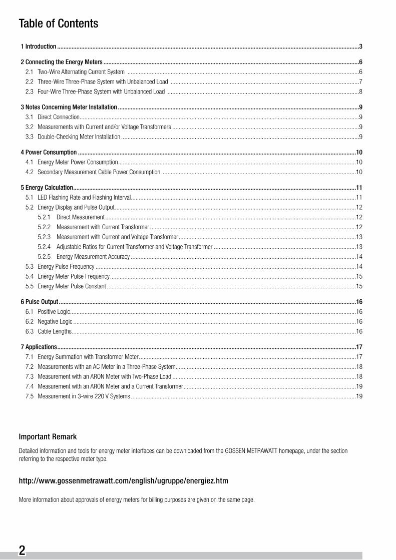
Important Remark
Detailed information and tools for energy meter interfaces can be downloaded from the GOSSEN METRAWATT homepage, under the section referring to the respective meter type.
http://www.gossenmetrawatt.com/english/ugruppe/energiez.htm
More information about approvals of energy meters for billing purposes are given on the same page.
Table of Contents
1 Introduction .............................................................................................................................................................................................3
2 Connecting the Energy Meters ................................................................................................................................................................6
2.1 Two-Wire Alternating Current System .................................................................................................................................................6
2.2 Three-Wire Three-Phase System with Unbalanced Load ......................................................................................................................7
2.3 Four-Wire Three-Phase System with Unbalanced Load ........................................................................................................................8
3 Notes Concerning Meter Installation .......................................................................................................................................................9
3.1 Direct Connection ...............................................................................................................................................................................9
3.2 Measurements with Current and/or Voltage Transformers .....................................................................................................................9
3.3 Double-Checking Meter Installation .....................................................................................................................................................9
4 Power Consumption ..............................................................................................................................................................................10
4.1 Energy Meter Power Consumption .....................................................................................................................................................10
4.2 Secondary Measurement Cable Power Consumption ..........................................................................................................................10
5 Energy Calculation .................................................................................................................................................................................11
5.1 LED Flashing Rate and Flashing Interval.............................................................................................................................................11
5.2 Energy Display and Pulse Output .......................................................................................................................................................12
5.2.1 Direct Measurement .............................................................................................................................................................12
5.2.2 Measurement with Current Transformer .................................................................................................................................12
5.2.3 Measurement with Current and Voltage Transformer ...............................................................................................................13
5.2.4 Adjustable Ratios for Current Transformer and Voltage Transformer .........................................................................................13
5.2.5 Energy Measurement Accuracy .............................................................................................................................................14
5.3 Energy Pulse Frequency ...................................................................................................................................................................14
5.4 Energy Meter Pulse Frequency ..........................................................................................................................................................15
5.5 Energy Meter Pulse Constant ............................................................................................................................................................15
6 Pulse Output ..........................................................................................................................................................................................16
6.1 Positive Logic ...................................................................................................................................................................................16
6.2 Negative Logic .................................................................................................................................................................................16
6.3 Cable Lengths ..................................................................................................................................................................................16
7 Applications ...........................................................................................................................................................................................17
7.1 Energy Summation with Transformer Meter ........................................................................................................................................17
7.2 Measurements with an AC Meter in a Three-Phase System .................................................................................................................18
7.3 Measurement with an ARON Meter with Two-Phase Load ...................................................................................................................18
7.4 Measurement with an ARON Meter and a Current Transformer ............................................................................................................19
7.5 Measurement in 3-wire 220 V Systems .............................................................................................................................................19

3
1 Introduction
The technologies used for the measurement of electrical energy (Wh) and the measurement of electrical power (W) are closely related.
The following applies regarding power in alternating current systems:
P = U · I or P = U · I · cos ϕ
For energy in alternating current systems the following:
W = P · t
For power in three-phase systems the following:
P = U1 · I1 + U2 · I2 + U3 · I3
For power in load balanced three-phase systems the following:
P = 3 · U · I (1) or P = 3 · ( U NPD · I ) · cos ϕ (2)
And for energy in three-phase systems the following:
W = P · t
Delta Voltage - Neutral-Point Displacement Voltage:
As a rule, delta voltage is used for the calculation of values in three-phase systems. Delta voltage and neutral-point displacement voltage can be derived from one another using a factor of √3.
U NPD = U Delta / √3 (3)
➞ ➞
➞ ➞ ➞ ➞ ➞ ➞
➞ ➞

4
ϕ ϕ
ϕU NPD U NPD (b)
U NPD (a)
U Delta
U Delta (c)U Delta
L1
L2 L2
Derivation of the Factor √3:
The following ensues from the cosine law and the angular relationships demonstrated by the voltage triangle shown below:
a = b = U NPD = 1 ; c = U Delta ; ϕ = 120° ; c2 = a2 + b2 - 2 · a · b · cos ϕ ⇒
U Delta = √( 12 + 12 - 2 · 1 · 1 · cos 120° ) = √( 1 + 1 - 2 · ( -0,5 ) ) = √3
If the above equation (3) is applied to the power equation, (1) or (2), the following results:
P = 3 · U Delta / √3 · I · cos ϕ
Because it is generally assumed that we are concerned with delta voltage, or phase-to-phase voltage, when dealing with three-phase systems, the index is ignored.
The quotient equation 3 / √3 = √3 results in the following:
P = √3 · U · I · cos ϕ
Respective power „P“ must be multiplied by time „t“ for the measurement of energy.

5
The Technical Realization of Energy Measurement:
The measurement of energy is accomplished by means of a voltage-frequency converter connected downstream from the power meter. The individual pulses are then summated through the use of an electromechanical meter, and are made available at a pulse output as well.
A single-phase meter is used in alternating current systems.
A measuring system with three multipliers is required for 4-wire three-phase systems of unbalanced load with neutral conductor (N). The „three-wattmeter method“ can also be used in the absence of a neutral conductor if an artificial neutral is available. This method results in a highly accurate measurement if a precision wattmeter is used.
However, 3-wire three-phase systems are commonly found in industrial applications, for which ARON circuits are used. This type of measuring circuit offers cost advantages because it allows for the measurement of power and energy with only two current transformers at phase conduc-tors L1 and L3. However, this measurement only provides correct results if the vector sums of all currents to be measured in the system are equal to zero (I1 + I2 + I3 = 0). This condition can only be fulfilled when no currents flow to earth (leakage current of a capacitive, an inductive or a resistive nature).
The theory of the ARON circuit can be demonstrated with the following equations:
(1) P = UL1 · IL1 + UL2 · IL2 + UL3 · IL3
(2) IL1 + IL2 + IL3 = 0
(3) from (2) IL2 = – IL1 – IL3
(3) to (1) P = UL1 · IL1 + UL2 · ( – IL1 – IL3 ) + UL3 · IL3
(4) P = IL1 · ( UL1 – UL2 ) + IL3 · (UL3 – UL2)
The terms (UL1 - UL2) and (UL3 - UL2) represent delta voltage.
UL1, UL2 and UL3 are the corresponding conductor voltages to earth or any desired virtual reference point. The above equations are to be inter-preted vectorially.
L1
L2
L3
L 1 – L 2
I
I
U
U
Load
L 3 – L 2
I 1
I 2
I 3
6
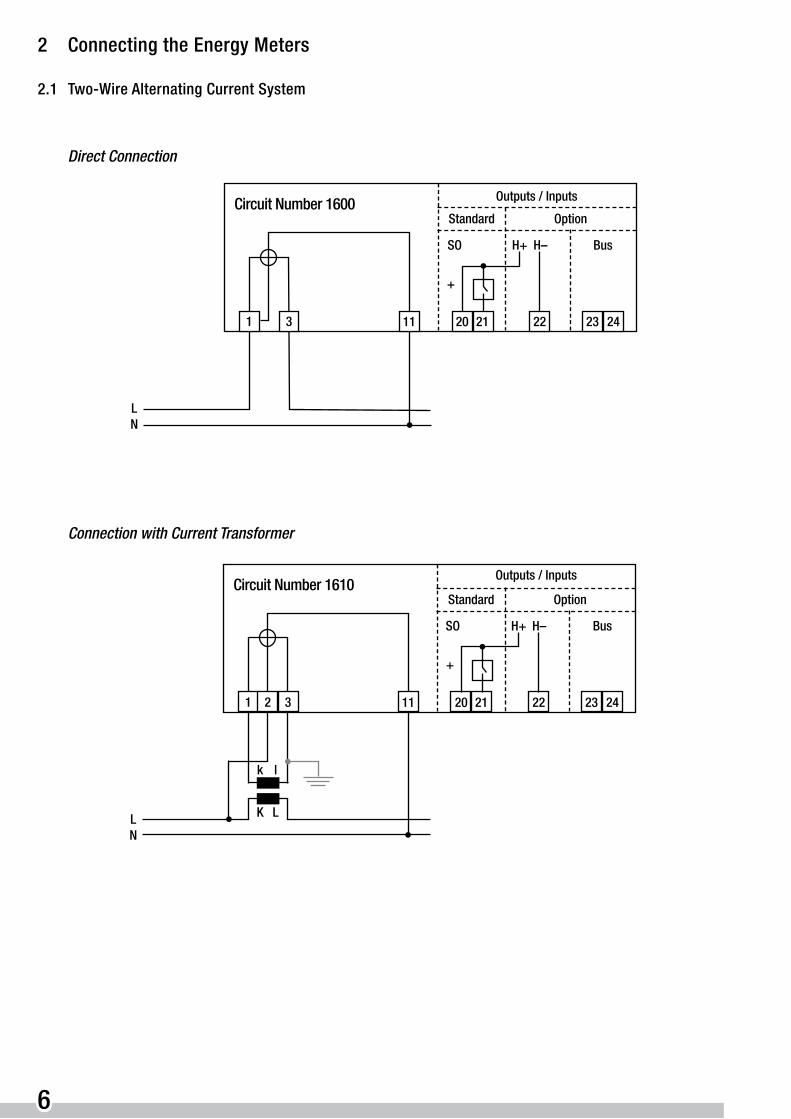
2 Connecting the Energy Meters
2.1 Two-Wire Alternating Current System
Direct Connection
11 20 21 22 23 2431
Outputs / Inputs
Standard Option
+
LN
Circuit Number 1600
BusH+SO H–
Connection with Current Transformer
11 20 21 22 23 2431
Outputs / Inputs
Standard Option
+
LN
Circuit Number 1610
BusH+SO H–
2
k l
K L

7
2.2 Three-Wire Three-Phase System with Unbalanced Load
Connection with Current Transformer
20 21 22 23 2431
Outputs / Inputs
Standard Option
+
L1L2
Circuit Number 3610
BusH+SO H–
2
k l
K L
8
K L
L3
5
k l
7 9
Connection with Current Transformer and Voltage Transformer
L1L2L3
20 21 22 23 2431
Outputs / Inputs
Standard Option
+
Circuit Number 3620.M7
BusH+SO H–
2
k l
K L
8
K L
5
k l
7 9
ux
ux
ux
XU
XU
XU
8
ux
ux
XU
XU
L1L2L3N
ux
XU
k l
K L K L
k lk l
K L
Outputs / Inputs
Standard OptionCircuit Number 4620.M1
BusH+SO H–
20 21 22 23 2431
+
2 85 7 9 114 6
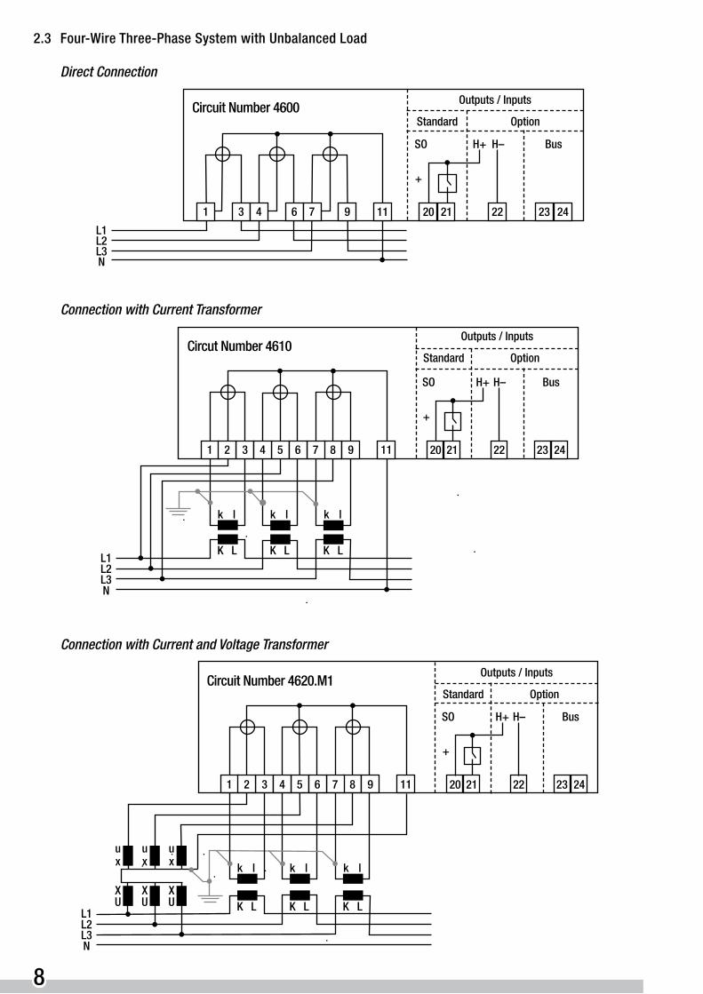
2.3 Four-Wire Three-Phase System with Unbalanced Load
Direct Connection
Outputs / Inputs
11 20 21 22 23 2431
Standard Option
+
L1
N
Circuit Number 4600
BusH+SO H–
64
L2L3
97
Connection with Current Transformer
Connection with Current and Voltage Transformer
Outputs / Inputs
Standard OptionCircut Number 4610
20 21 22 23 2431
+
L1L2
BusH+SO H–
2
k l
K L K L
L3
k l
7 9 11
k l
K L
4 6
N
5 8

9
3 Notes Concerning Meter Installation
3.1 Direct Connection
■ All phases should be protected in front of the meter with 63A fuses. The voltage path is directly connected inside the meter with the current path and can not be fused separately.
■ Voltage terminals 2, 5 and 8 must be tightened down for meter types U1281, U1289, U389A, in order to establish a connection between the current and voltage circuits.
3.2 Measurements with Current and/or Voltage Transformers
■ All phases should be protected in front of the meter with 63A fuses. There might not be any fuse in the secondary side of the transformers. Normally it is not necessary to fuse the direct connected voltage path. Nevertheless, if the voltage path should be fused, the dimension should be done in respect of the maximum power consumption of 10 VA per phase.
■ The connections between the transformers and the meters (k,l / u,v / u,x - see schematic diagrams) must be in compliance with corresponding regulations.
■ The secondary side of the current and voltage transformers should be grounded.
■ Never operate the current transformer with an open circuit: short circuit before disconnecting the meter from the system. A second terminal block between the current transformer and the meter simplifies service work.
■ When measurements are performed with upstream transformers, the displayed energy value must be multiplied by the transformation ratios. The meter is provided with a field to which entries can be made for this purpose (CT or VT factor).
3.3 Double-Checking Meter Installation
The following points must be observed in order to assure that the meter functions properly:
■ For U128X, U138X meters: is the red LED flashing? For U389X meters: is the red LED with designation ‚Imp./kWh‘ flashing ?
■ Are the current transformers connected correctly and functioning properly? Improperly connected current transformers are the most common cause of incorrect measurements. U128X and U138X meters signal current transformers with reversed polarity with a flashing of the respective phase symbol in the display. U389X meters signal current transformers with reversed polarity with the reverse LED lit up.
■ Are the individual phases properly connected and is the phase sequence correct? U128X, U138X meters signal incorrect phase sequence with the phase symbols flashing in the sequence 3-2-1, and phase failure is indicated by suppressing the associated phase symbol.
■ Check the measured power value. Perform a current measurement and calculate power based upon applied voltage. Compare the theoretically calculated value with the power value displayed in U128X, U138X meters or with the flashing rate of the Imp./kWh LED in U389X meters (see chapter 5.1). The results of this method, however, are only valid if the cos ϕ is known and has been taken into consideration in the calculation.

10
4 Power Consumption
If a meter is used in combination with a current transformer. nominal power for the current transformer is calculated based upon energy meter and secondary measurement cable power consumption. The following applies:
ASec ≈ A Cable + A Meter
A = Apparent Power (VA)
4.1 Energy Meter Power Consumption
■ Voltage Circuit
Power required for the electronics in the meter is supplied via the voltage circuit.
The following values apply: 2-Wire Meter < 5 VA
3 and 4-Wire Meters < 3 VA per phase
■ Current Circuit
Current circuit power consumption values: where Imax < 1 VA
where IB = 1 A < 0.02 VA
where IB = 5 A < 0.5 VA
where IB = 10 A < 0.02 VA
4.2 Secondary Measurement Cable Power Consumption
The following table includes estimated values for apparent cable power (VA) as a function of cable length and cross section.
Secondary Current
Cross Section Cable Length ( forward and return cables )
A mm 2 0.5 m 1.0 m 2.5 m 5 m 10 m
5 A 1.5 0.3 VA 0.6 VA 1.5 VA 2.9 VA 5.8 VA
5 A 2.5 0.2 VA 0.4 VA 0.9 VA 1.8 VA 3.6 VA
5 A 4.0 – – 0.6 VA 1.1 VA 2.2 VA
1 A 1.0 0.02 VA 0.04 VA 0.09 VA 0.18 VA 0.35VA
1 A 1.5 0.01 VA 0.03 VA 0.06 VA 0.12 VA 0.23 VA
1 A 2.5 0.01 VA 0.02 VA 0.04 VA 0.07 VA 0.14 VA
11
5 Energy Calculation
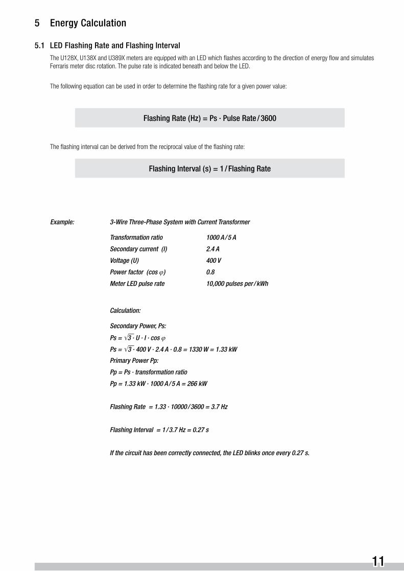
5.1 LED Flashing Rate and Flashing Interval
The U128X, U138X and U389X meters are equipped with an LED which flashes according to the direction of energy flow and simulates Ferraris meter disc rotation. The pulse rate is indicated beneath and below the LED.
The following equation can be used in order to determine the flashing rate for a given power value:
Flashing Rate ( Hz ) = Ps · Pulse Rate / 3600
The flashing interval can be derived from the reciprocal value of the flashing rate:
Flashing Interval ( s ) = 1 / Flashing Rate
Example: 3-Wire Three-Phase System with Current Transformer
Transformation ratio 1000 A / 5 A
Secondary current ( I ) 2.4 A
Voltage ( U ) 400 V
Power factor ( cos ϕ ) 0.8
Meter LED pulse rate 10,000 pulses per / kWh
Calculation:
Secondary Power, Ps:
Ps = √ 3 · U · I · cos ϕ
Ps = √ 3 · 400 V · 2.4 A · 0.8 = 1330 W = 1.33 kW
Primary Power Pp:
Pp = Ps · transformation ratio
Pp = 1.33 kW · 1000 A / 5 A = 266 kW
Flashing Rate = 1.33 · 10000 / 3600 = 3.7 Hz
Flashing Interval = 1 / 3.7 Hz = 0.27 s
If the circuit has been correctly connected, the LED blinks once every 0.27 s.

12
5.2 Energy Display and Pulse Output
Energy values can either be read from the display or from the drum-type counter mechanism at the meter. Alternatively, it can be integrated and calculated at a distant point with the help of pulses provided by the meter.
The 7-place display or electromechanical counter mechanism indicates imported energy at a resolution of 0.1 kWh for direct measurement meter types and with a resolution of 0.01 kWh for transformer type meters.
The pulse constant for the pulse output at the meter is indicated at the serial plate.
5.2.1 Direct Measurement
Calculation of Consumed Energy:
Consumed Energy = Displayed Energy
Output Pulse Calculation:
Energy per Pulse = 1 /Pulse Constant
Example: Meter Pulse Constant = 100 pulses per kWh Energy per Pulse = 0.01 kWh per pulse
5.2.2 Measurement with Current Transformer
Calculation of Consumed Energy:
Consumed Energy = Displayed Energy · Ti
Current Transformer Transformation Ratio:
Ti = Primary Current ( Ip ) / Secondary Current ( Is ) = CT-Factor
Example: Displayed Energy = 1.33 kWh Current Transformer Transformation Ratio Ti = 1000 A / 5 A Consumed Energy = 1.33 kWh · 1000 A / 5 A = 266 kWh
Output Pulse Calculation:
Energy per Pulse = Ti / Pulse Constant
Example: Meter Pulse Constant = 1,000 pulses per kWh Energy per Pulse = (1000 A / 5 A) / 1000 kWh per pulse = 0.2 kWh per pulse
13
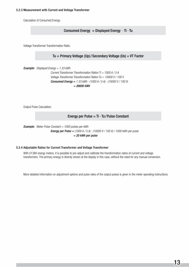
5.2.3 Measurement with Current and Voltage Transformer
Calculation of Consumed Energy:
Consumed Energy = Displayed Energy · Ti · Tu
Voltage Transformer Transformation Ratio:
Tu = Primary Voltage ( Up ) / Secondary Voltage (Us) = VT Factor
Example: Displayed Energy = 1.33 kWh Current Transformer Transformation Ration Ti = 1000 A / 5 A Voltage Transformer Transformation Ration Tu = 10000 V / 100 V Consumed Energy = 1.33 kWh · (1000 A / 5 A) · (10000 V / 100 V) = 26600 kWh
Output Pulse Calculation:
Energy per Pulse = Ti · Tu / Pulse Constant
Example: Meter Pulse Constant = 1000 pulses per kWh Energy per Pulse = (1000 A / 5 A) · (10000 V / 100 V) / 1000 kWh per pulse = 20 kWh per pulse
5.2.4 Adjustable Ratios for Current Transformer and Voltage Transformer
With U138X energy meters, it is possible to pre-adjust and calibrate the transformation ratios of current and voltage transformers. The primary energy is directly shown at the display in this case, without the need for any manual conversion.
More detailed information on adjustment options and pulse rates of the output pulses is given in the meter operating instructions.

14
5.2.5 Energy Measurement Accuracy
The level of accuracy attained during measurement depends upon the accuracy class of the energy meter and allowable influence errors. The accuracy class indicates allowable error during operation under reference conditions, i.e. with defined values for power factor, voltage, waveform and ambient temperature.
If actual condition deviate from reference conditions, additional influence error is allowed. Influence error for each influencing quantity within a defined range (nominal range of use) is included in the data sheet.
Additional error occurs under the following conditions:
■ Reversed connections: If the connections for the voltage and current circuits in three-phase systems are reversed, measuring errors ranging from minimal to extreme may occur.
■ Measuring transducer error: If the energy meter is connected to the system via measuring transducers, (current or voltage transformer) their intrinsic error must also be taken into consideration.
■ If energy is measured over short periods of time, an excessively short pulse rate (insufficient resolution) may lead to significant error, if the available quantity of electricity at the end of the energy import period is no longer sufficient for triggering the last pulse. Maximum error: (1 / n) x 100% n = number of pulses.
5.3 Energy Pulse Frequency
The optimum pulse frequency value for the forwarding of pulses is dependent upon a variety of transmission line and processing equipment factors.
The following must be considered where maximum pulse frequency prevails:
■ How high should measurement resolution be set (Ws per pulse)?
■ What is the maximum pulse frequency which can be processed?
■ Allowable relay operating cycles and switching frequency?
■ Simultaneous reading of several meters is only possible with low pulse frequencies!
■ A lower pulse frequency results in a longer interpulse period, and thus increases the danger of error due to disturbance pulses.
15
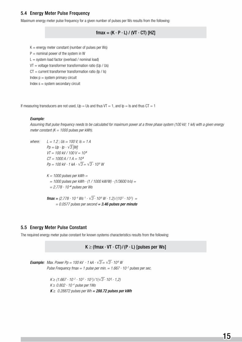
5.4 Energy Meter Pulse Frequency
Maximum energy meter pulse frequency for a given number of pulses per Ws results from the following:
fmax = (K · P · L) / (VT · CT) [HZ]
K = energy meter constant (number of pulses per Ws)
P = nominal power of the system in W
L = system load factor (overload / nominal load)
VT = voltage transformer transformation ratio (Up / Us)
CT = current transformer transformation ratio (Ip / Is)
Index p = system primary circuit
Index s = system secondary circuit
If measuring transducers are not used, Up = Us and thus VT = 1, and Ip = Is and thus CT = 1
Example: Assuming that pulse frequency needs to be calculated for maximum power at a three phase system (100 kV; 1 kA) with a given energy meter constant (K = 1000 pulses per kWh).
where: L = 1.2 ; Us = 100 V; Is = 1 A Pp = Up · Ip · √ 3 [W] VT = 100 kV / 100 V = 10 3
CT = 1000 A / 1 A = 10 3
Pp = 100 kV · 1 kA · √ 3 = √ 3 · 10 8 W
K = 1000 pulses per kWh = = 1000 pulses per kWh · (1 / 1000 kW/W) · (1/3600 h/s) = = 2.778 · 10 -4 pulses per Ws
fmax = (2.778 · 10 -4 Ws -1 · √ 3 · 10 8 W · 1.2 ) / ( 10 3 · 10 3 ) = = 0.0577 pulses per second = 3.46 pulses per minute
5.5 Energy Meter Pulse Constant
The required energy meter pulse constant for known systems characteristics results from the following:
K ≥ ( fmax · VT · CT ) / ( P · L ) [ pulses per Ws ]
Example: Max. Power Pp = 100 kV · 1 kA · √ 3 = √ 3 · 10 8 W Pulse Frequency fmax = 1 pulse per min. = 1.667 · 10 -2 pulses per sec.
K ≥ ( 1.667 · 10 -2 · 10 3 · 10 3 ) / 1( √ 3 · 10 8 · 1,2 ) K ≥ 0.802 · 10 -4 pulse per 1Ws K ≥ 0.28872 pulses per Wh = 288.72 pulses per kWh

16
6 Pulse Output
The pulse output at the meter is electrically isolated from the measuring circuit by means of an optocoupler and must be supplied with power from an external source.
6.1 Positive Logic
With positive logic, a pulse is forwarded to the analyzer. In the release condition, pulse output potential is equal to „0“.
6.3 Cable Lengths
A distance of up to 500 m between the meter and the analyzer is possible with a conductor cross section of 0.5 mm2. For distances of 500 to 1000 m, a signal cable with a cross section of 1.5 mm2 is used. As a rule, cables need not be shielded.
6.2 Negative Logic
The pulse output level is increased to high potential with a pull-up resistor in the release condition. A generated pulse causes output potential to approach „0“.
Pulse Output Schematic Diagram
Pulse Output
External Power Supply
U DC
+ –
20 (+)21
Meter Analyzer
External Power Supply
U DC
+ –
20 (+)21
Meter Analyzer
17
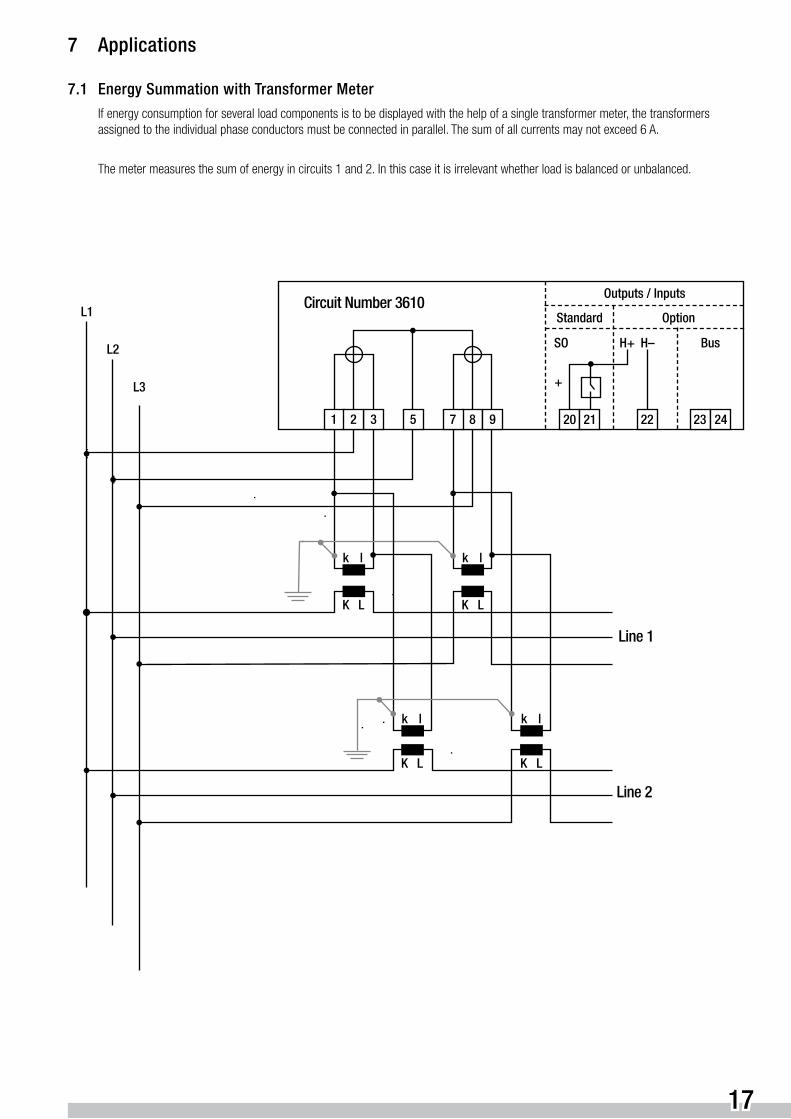
7 Applications
7.1 Energy Summation with Transformer Meter
If energy consumption for several load components is to be displayed with the help of a single transformer meter, the transformers assigned to the individual phase conductors must be connected in parallel. The sum of all currents may not exceed 6 A.
The meter measures the sum of energy in circuits 1 and 2. In this case it is irrelevant whether load is balanced or unbalanced.
20 21 22 23 2431
Outputs / Inputs
Standard Option
+
L1
L2
Circuit Number 3610
BusH+SO H–
2
k l
8
K L K L
L3
5
k l
7 9
k l k l
K L K L
Line 1
Line 2
18
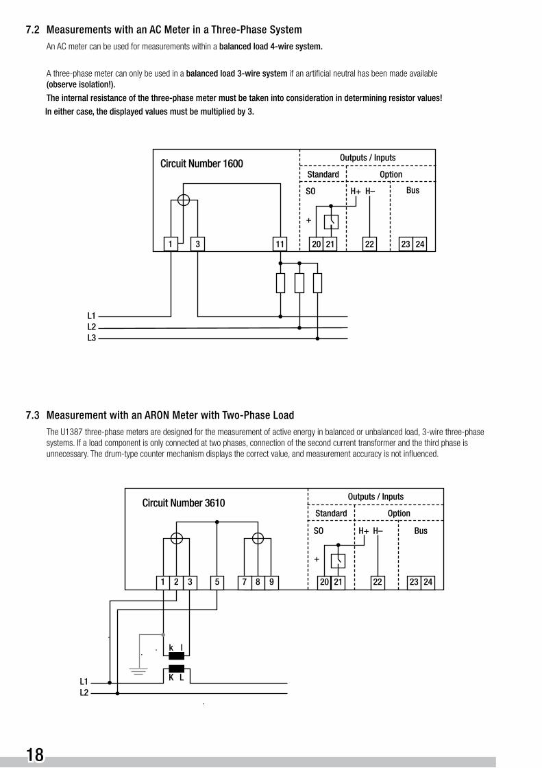
7.2 Measurements with an AC Meter in a Three-Phase System
An AC meter can be used for measurements within a balanced load 4-wire system.
A three-phase meter can only be used in a balanced load 3-wire system if an artificial neutral has been made available (observe isolation!).
The internal resistance of the three-phase meter must be taken into consideration in determining resistor values!
In either case, the displayed values must be multiplied by 3.
7.3 Measurement with an ARON Meter with Two-Phase Load
The U1387 three-phase meters are designed for the measurement of active energy in balanced or unbalanced load, 3-wire three-phase systems. If a load component is only connected at two phases, connection of the second current transformer and the third phase is unnecessary. The drum-type counter mechanism displays the correct value, and measurement accuracy is not influenced.
11 20 21 22 23 2431
Outputs / Inputs
Standard Option
+
L2L3
Circuit Number 1600
BusH+SO H–
L1
20 21 22 23 2431
Outputs / Inputs
Standard Option
+
L1L2
Circuit Number 3610
BusH+SO H–
2
k l
K L
85 7 9

19
7.4 Measurement with an ARON Meter and a Current Transformer
The U1387 three-phase meters are designed for the measurement of active energy in balanced or unbalanced load, 3-wire three-phase systems. Two current transformers are required for measurement in accordance with the ARON principle. They can also be used with a single current transformer for balanced load 3-wire systems, |I1| = |I2| = |I3|, if the artificial circuit shown below is employed. The drum-type counter mechanism displays the correct values independent of phase displacement (cos ϕ). The measurement accuracy of the meter is not influenced.
If export energy should be displayed at the counter mechanism instead of import energy, the direction of current flow through the meter must be reversed (k ➔ 1, l ➔ 9).
7.5 Measurement in 3-wire 220 V Systems
The U6 connection of the U1389 energy meter, which is deviating from standard practice, affects the functionality of the multifunctional display. Measuring quantities I1, I3, P and Q as well as energy ( kWh ) are shown correctly. Voltage U12 can be withdrawn from U1, and voltage U32 can be withdrawn from U3.
This circuit deviates from the wiring diagram located in the terminal cover at the meter. If this circuit is used, corresponding explanations must be entered into the systems plan and attached directly to the meter.
20 21 22 23 2431
Outputs Inputs
Standard Option
+
L1
L2
Circuit Number 3610
BusH+SO H–
2 8
L3
5
K L
k l
7 9
or L3 or L2
or L1 or L3
or L2 or L1
Outputs / Inputs
Standard OptionCircuit Number 4610
20 21 22 23 2431
+
L1L2
BusH+SO H–
2
k l
K L
8
K L
L3
5
k l
7 9 114 6

GMC-I Messtechnik GmbHSüdwestpark 15 90449 Nürnberg, GermanyPhone: +49 911 8602-111Fax: +49 911 8602-777E-Mail: [email protected]
Printed in Germany • Subject to change without notice • 3/10.09 • 3-337-059-03