electric service requirements book 2014-9.pdf · comment and electrical service requirements book...
TRANSCRIPT
ELECTRIC SERVICE
REQUIREMENTS
BOOK
2014-9

Comment and Electrical Service Requirements Book Change Form
This form may be utilized to communicate any recommended changes or any comments regarding the information
contained within this book or how the information is organized. Please complete the form in sufficient detail to
communicate clearly any proposed changes and please be sure to include the name, address, and telephone number of a
person to contact should additional information be required. Include additional documentation if necessary.
Date:
Requester Name: Telephone Number: _________________
Business Name: E-mail address:
Address:
Comments:
Please Mail to:
Trico Electric Cooperative, Inc.
Attn: Standards Committee – Justin Banales
P. O. Box 930
Marana, AZ 85653-0930
Trico Use Only
Date received: ESRB Updated
Reviewed by: Yes
Date forwarded to Standards Committee: No
Reviewed by:
Comments:
Action: Approved Under Study Not Approved
Does the Committee action impact the Public? Yes No
Will a Public notification letter need to be sent out? Yes No Sent
Comments:
Signed by: Date:

Electric Service Requirements 2014-9
iii
Table of Contents
1. General Requirements
1.1 General Definition ….……....…...……...…………………………………...………14
1.2 Booklet Purpose and Organization …...……………………………………...………..14
1.3 Changes or Conflicts in Requirements………………………...……...…………..14
1.4 Maximum Available Fault Current………….…………………………………….14
1.5 Customer's Responsibility for Safety ………………...………………………...…….15
1.6 Work Activity Near High-Voltage Overhead Power Lines (Over 600 Volts)……………..15
1.7 Service Interruption ………………………...………………………….…...……….16
1.8 Grounding and Bonding ………………………...………………………..…...……..16
1.9 Protection of Cooperative Equipment (Barrier Post) …………..………...………..….16
1.10 Trees and Shrubs………………………...…….……………………...…………….16
1.11 Power Factor ………………………...………………………………...……...….16
1.12 Time-Of-Use Metering………………………...………...………...…………….17
1.13 Call Before You Dig ………………………...………………...……………………17
1.14 Power Quality ………………………...………………...………………………….17
1.15 Motors ………………………...……………………..……………………………18
1.16 Customer Generation………………………...…………..….………………………19

Electric Service Requirements 2014-9
iv
2. Permits
2.1 Codes and Ordinances ………………………...……..……….………….………….23
2.2 Rights-of-Way ………………………...………..………….…………………….23
2.3 Application for Service…………………………......……………………………….24
3. Services
3.1 Types of Service Furnished………………………...…...…………………...……….26
3.2 Permanent Service Connection………………………...……………………………..26
3.3 General Meter Installations………………………...……………...………………....27
3.4 Connection and Disconnection of Service ……………………………..……..……….29
3.5 Relocation of Services and Facilities ………………………...………...…….……….29
3.6 Customer Equipment on Cooperative Poles ……………………...……………...…...29
3.7 Load Requirements ………………………...……………...……………….……….29
4. Temporary Construction Service
4.1 General ………………………...…………………………...……………………...32
4.2 Construction Criteria for Temporary Service ………………...…………...……..32
5. Clearances
5.1 Meter Clearances and Locations ……..………………………………..….………….41
5.2 Clearances from Pools, Spas or Hot Tubs ………………………...………...…………47
5.3 Clearance from Underground Gasoline Storage Tanks …………..…….…...,…………47
5.4 Clearance from Padmounted Transformer……………………..……....…….………..47
6. Underground Requirements
6.1 Underground Service………………….……...………………..…………….………50
Electric Service Requirements 2014-9
v
6.2 Trenches Provided by the Customer………………...…………..…………….……….51
6.3 Conduit ………………………...………………………..……………….……….59
6.4 Concrete Pads and Vaults for Padmount Transformers ………………...…………...….60
7. Single Family Service
7.1 General ………………………...………………………………...…………….…..63
7.2 Underground Service ………………………...……………………...……………….64
7.3 Overhead Service ………………………...……………………...………………….74
8. Multiple Family Service
8.1 General ………………………...………..……………………………...…………84
8.2 Underground Service ………………………….....………………………………….84
8.3 Overhead Service ………………………...………..………………………………...84
9. Manufactured and Mobile Home Service
9.1 Underground Service Information ……………………….…...……………………….87
9.2 Underground Service to Manufactured Home Sockets ………..………..……………….87
9.3 Underground Service to Mobile Homes ………………………….....………………….87
9.4 Installation of Pedestal and Post Meters for Underground Service ……..………………...87
9.5 Overhead Service Information ………………………......…………..……………87
9.6 Overhead Service to Manufactured Homes ……………………….....………..……….88
9.7 Overhead Service to Mobile Homes ………………………...……………..………….88

Electric Service Requirements 2014-9
vi
10. Commercial, Industrial, Agricultural Services
10.1 Self—contained Metering ……………………………...……………...…..…….. 90
10.2 Current Transformer Metering — 800 Amps Maximum ……………........………...97
10.3 Switchboard Metering ………………………...………………………………….106
10.4 Primary Voltage Service {Over 600 Volts) …………………..……….......……….114
NOTE:
Revisions to this book from the proceeding publication are noted by a black bar, shown in the
left margin, as depicted here.
Electric Service Requirements 2014-9
7
Definitions
AHJ – Authority Having Jurisdiction- A person who has the delegated authority to determine,
mandate, and enforce code requirements established by jurisdictional governing bodies.
ANSI - American National Standards Institute.
Bushings - Plastic or nylon rings that attach to the ends of conduit to protect the electrical cable from
sharp edges.
Bypass - A method which allows for service continuity to the customer while the meter is removed
for test or inspection.
Cooperative - The respective Cooperative providing electrical service to a customer.
Current - Amperes
Current Transformer – A transformer that accurately ratios input current to output current to
provide a low current input to devices such as meters.
Current Transformer Meter - A meter that requires current transformers because its current
rating is not as large as the Customer's current load, also known as a transformer rated meter
Customer - The individual responsible for or requesting electrical service from the Cooperative.
Direct-burial Cable - Electrical cable that is suitable (approved by a nationally recognized
testing laboratory) for direct burial in the ground without using a conduit system.
Direct-connect Meter - Meter that is energized to line voltage and carries all the load current. Also
known as a self-contained meter.
Drip Loop - The loop formed by the customer’s service entrance conductors, below the customers
weather head, that connects to the Cooperative’s service drop. The conductors are formed in a
downward "loop" so water will not enter the customer's service mast (weather head).
EUSERC - Electrical Utility Service Equipment Requirements Committee
Fault Current - Maximum available current under short circuit conditions.
Grounding - Grounding must be in accordance with latest issue of NEC (Article 250-Grounding).
Code enforcement agencies may require ground connection to be visible when inspection is made.
IMC - Intermediate Metallic Conduit

Electric Service Requirements 2014-9
8
Definitions (Continued)
Manual Link Bypass – Meter Base bypass facilities requiring the physical act of placing links
across line and load buss studs (see bypass) provided in the meter socket.
Manufactured Home - A factory-assembled structure or structures, site specific and transportable
in one or more sections that is designed to be used as a dwelling with a permanent foundation (see
section 9).
Meter - A device that measures and records the summation of electrical quantity over a period of
time.
Meter Base - The mounting device consisting of jaws, connectors, and enclosure for socket-type
meters. The meter base is also referred to as a meter socket.
Meter Base Ring - A metallic ring that secures the meter to the meter base that can be sealed by the
Cooperative.
Meter Pedestal - A commercially built pedestal that contains a service entrance section for
landing underground service conductors, a meter socket and customer disconnect switches or
circuit breaker section.
Meter Socket - Mounting device consisting of jaws, connectors, and enclosure for socket-type
meters.
Mobile Home - A factory-assembled structure or structures transportable in one or more sections
that is built on a permanent chassis and designed to be used as a dwelling without a permanent
foundation.
Modular Home - A factory-assembled structure or structures transportable in one or more sections
that is built on permanent chassis and designed to be used as a dwelling with a permanent
foundation.
NEC - The most recent publication of the National Electrical Code adopted by the state.
NESC - The most recent publication of the National Electrical Safety Code- adopted by
the State
NFGC - The most recent publication of the National Fuel Gas Code.
OSHA - Occupational Safety and Health Administration
Overhead Service - Electric service supplied to the customer from the Cooperative utilizing
overhead conductors.

Electric Service Requirements 2014-9
9
Definitions (Continued)
Point of Delivery – (POD) The point where facilities owned, leased, or under license by a
customer connects to the Cooperative’s facilities, as denoted in the Cooperative’s service
specifications or by written agreement. The Cooperative shall determine the Point of Delivery in
all cases.
Plumb - Level alignment of Customer mounted enclosures. To have the sides and front of the meter
base perfectly vertical from both the front and side views.
Primary - Over 600 volts
Primary Voltage – The Cooperatives Distribution system voltage(s)
Power Factor - The cosine of the angle, expressed as a percent, between voltage and current. The
ratio of the active power to the apparent power.
PVC Conduit – Polyvinyl Chloride (PVC) conduit, manufactured to schedule 40 thickness, approved
for use in electrical installations. Commonly referred to as plastic conduit or duct and gray in color.
Secondary - 600 volts and under.
Safety Socket – A device consisting of a manual link bypass facility, circuit closing nut and bolt
assembly which will de-energize the meter socket for meter removal.
Self-contained - See direct-connect meter.
Select Backfill Material - Material used to bed and cover direct-burial cables or conduit. It consists
of screened native soil or sand free of sharp or foreign objects, also called “shading material”.
Service Drop - The overhead service conductors from the Cooperative pole to the customer's house
or customer owned service pole.
Service Entrance Conductors - Overhead - The Customers service conductors between the
terminals of the service equipment and the point where joined by tap or splice to the service drop.
Service Entrance Conductor - Underground - The Customers service conductors between the
terminals of the service equipment and the point of connection to the service lateral
Service Equipment- The necessary equipment, usually consisting of a circuit breaker, switch or
fuse located near the point of entrance of supply conductors to a building, structure or other defined
area, intended to constitute the main control and means to cut off the supply.

Electric Service Requirements 2014-9
10
Definitions (Continued)
Service Lateral - The underground service conductors between the street, alley or easement,
including any risers at a pole, transformer or structure and the first point of connection to the service
entrance conductors in a terminal box, meter or other enclosure with adequate space.
Service Trench - Trench provided by Customer for service lateral.
Switchboard - A large panel or assembly of panels that may contain buses, current transformers,
meters, switches, and protective devices.
Test Block (TBF) - An assembly used to de-energize a self-contained meter socket without
discontinuing electric service to the Customer.
Test Switch – An isolation, testing and measuring device, used by the Cooperative associated
with current transformer metering.
UL - Underwriters Laboratory

Electric Service Requirements 2014-9
11
This Page Left Intentionally Blank

Electric Service Requirements 2014-9
12
Office/Payment Locations
Main Office:
Trico Electric Cooperative, Inc.
8600 W. Tangerine Rd., Marana Az.
(520) 744-2944
Mail Billing Payments to:
Trico Electric Cooperative, Inc.
Remittance Center
P.O. Box 80072
Prescott, Az. 86304-8094
E-Bill: Pay your bill online using your checking account, VISA, MasterCard or Discover card.
It’s fast, simple and free! You can even view your current and past bills, payment history, and
energy usage graphs. There is no need for a paper bill and you can opt out of paper bills
completely if you wish.
Pay By Phone: Direct connection, no menus to navigate. Inquire and make payments on your
bill. Update your phone number in our records. Call toll free at 1-866-999-8441.
Automatic Payment/Bankdraft: With Bankdraft, your monthly electric bill can be paid from
your checking or savings account on the date it’s due. Call Trico’s Member Services at 744-
2944 to sign up. You can also set up an automatic payment at trico.smarthub.coop.
Wal-Mart: Pay your Trico Electric Bill at any Wal-Mart Store- Just take your Trico Electric
Bill stub to the customer service desk. You can pay with cash, Wal-Mart money order or a PIN
based debit card. (Sorry no checks or credit cards) Wal-Mart asses a fee for this service.


Electric Service Requirements 2014-9
14
1. General Requirements
1.1 General Definition
To prevent unnecessary repetition in this booklet, the Cooperative used in the
following pages shall refer to Trico Electric Cooperative, Inc. (TRICO).
The Customer is the person or entity in whose name service is rendered, as evidenced
by the signature on the application or contract for that service, or by receipt or
payment of bills regularly issued in his name regardless of the identity of the actual
user of the service.
The term "consult Cooperative" means the customer shall obtain Cooperative approval
prior to any act towards installation. This term applies to each and every installation
involved. Failure to receive approval will result in denial of service until the
installation meets the Cooperative's approval.
1.2 Booklet Purpose and Organization
This booklet was prepared to aid you in obtaining service from the Cooperative. This
booklet applies to new services, relocated services and service alterations. If additional
information is required, please call the Cooperative office.
1.3 Changes or Conflicts in Requirements
These requirements are issued with the intent of complying will all applicable codes,
ordinances, and rates. However, in the case of conflict, the appropriate rate, code, or
ordinance supersedes the interpretation offered in this booklet. In addition, these
requirements may change if governing codes, ordinances, or rates change. The
Cooperative does not assume responsibility for keeping this book current and should
be consulted when questions arise on the applicability of any item. The Cooperative
reserves the right to modify, update, and release future editions of this book as
required by the Cooperative.
1.4 Maximum Available Fault Current
The maximum available fault current will depend on the ampacity and voltage class of
service being provided. It is the Customer's responsibility to furnish equipment to
withstand and or interrupt maximum fault currents. Upon request, and in receipt of
service entrance data required and supplied by the Customer, the Cooperative will
supply information on maximum available fault current at the Customer's service
entrance.

Electric Service Requirements 2014-9
15
1.4.1 Single Family Residential (200 Amperes)
For single family residences with services that are 200 amperes, the Customer
is responsible for furnishing equipment that will withstand the maximum fault
current available from the Cooperative. The Cooperative will provide the
maximum available fault current to the Customer upon request.
1.4.2 Single Family Residential (Larger than 200 Amperes)
For single family residences with services that are larger than 200 amperes, the
Customer is responsible for furnishing equipment that will withstand the
maximum fault current available from the Cooperative. The Cooperative will
provide the maximum available fault current to the Customer upon request.
1.4.3 Commercial, Industrial, Agricultural, and Multi-Family Services
The Customer is responsible for furnishing equipment that will withstand the
maximum fault current available from the Cooperative. The Cooperative will
provide the maximum available fault current to the Customer upon request.
1.5 Customer's Responsibility for Safety
The Customer shall comply with federal, state, and local laws and regulations
concerning activities in the vicinity of the Cooperative's electrical lines and equipment.
The Customer shall comply with all laws and regulations to protect themselves, their
family, their employees, the Cooperative and its employees, contractors and all third
parties from injury, loss, or damage.
If the Cooperative serves the Customer by means of primary voltage service or
transmission voltage service on the Customer's premises or if the Customer resells
power and energy furnished by the Cooperative the Cooperative may require the
Customer to obtain and maintain insurance coverage which the Cooperative deems
adequate to satisfy the duty of indemnification. The Cooperative may also require a
separate indemnification, hold harmless, and/or additional named insured agreement.
It is the responsibility of the Customer to plan for Cooperative transformer locations with
sufficient separation from buildings and obstructions. All transformer locations are
subject to Cooperative approval. See Figure 5-4 for padmount transformer clearances.
1.6 Work Activity near High-Voltage Overhead Power Lines (Over 600 Volts)
Arizona Revised Statute 40-360.42 thru .45 requires that no work take place within close
proximity of high-voltage overhead power line. The following are two requirements:

Electric Service Requirements 2014-9
16
The responsible party must notify the Cooperative of the intended work activity a
minimum of three working days prior to construction work. More lead time may be
required depending on the work to be done.
The responsible party and the Cooperative must agree to a mutually satisfactory
method to accomplish the activity safely.
1.7 Service Interruption
The Cooperative may temporarily suspend service to make repairs, replacements,
maintenance, tests or inspections of Cooperative equipment or to make tests, inspections,
connections or disconnections of Cooperative service. The Cooperative shall make
reasonable efforts to notify the Customer about the need for and the duration of a planned
service interruption, but it may suspend service in an emergency situation without prior
notice to the Customer.
1.8 Grounding and Bonding
Grounding and bonding is critical for safety and electrical reliability. The Customer is
responsible to ensure that the electrical service equipment is grounded and bonded in
accordance with the applicable requirements of the local (AHJ), and NEC requirements.
1.9 Protection of Cooperative Equipment (Barrier Post)
The Customer is responsible for providing barrier posts for protection of electrical
equipment. When vehicles or other equipment can be near or around Cooperative
equipment, barrier post(s) constructed with four inch diameter steel, concrete filled, will
be required. Consult the Cooperative for barrier post requirements for areas subject to
vehicles or other equipment access. (See Figure 6.3 for more detail).
1.10 Trees and Shrubs
The Customer shall prepare the premises so that trees, shrubs, and other vegetation will
not interfere with the proper access for construction, operation and maintenance of
Cooperative facilities, see Section 5 (Clearances). Consult the Cooperative for clearance
requirements of your specific installation or where electric facilities exist. For easements
and rights-of-way refer to section 2.2.
1.11 Power Factor
The Cooperative's current rate specifies a charge for low power factor for certain
commercial and industrial classes. The Cooperative recommends that the Customer
install corrective devices to make the most efficient use of the electrical system. The
Cooperative can provide a copy of the rate if the Customer would like to determine

Electric Service Requirements 2014-9
17
potential savings during design.
1.12 Time-of-Use Metering
The Time of Use rate requires special metering for residential, commercial, and
industrial loads. Time-of-Use rates may not be applicable for all Customer classes.
Contact the Cooperative for special requirements and for Time of Use rate information.
1.13 Call Before You Dig
State law requires the Customer/Excavator to call for underground utility cable locations
at least two full working days (48 hours) prior to excavation. Excavation must not start
until all locations have been marked or the utilities have informed the excavator that
they have no facilities in the area. Call 1-800-stakeit (782-5348) before you dig.
1.14 Power Quality
The characteristics of the Customer's electrical equipment and devices must not cause
undue interference to the Cooperative, or electric service to other Cooperative
Customers. Whenever a Customer's equipment has characteristics which cause undue
interference to the Cooperative or to other Cooperative Customers, the Customer must
make changes in such equipment or provide, at Customer expense, additional equipment
to eliminate the interference. If additional facilities are required by the Cooperative,
these facilities will be installed and maintained by the Cooperative at the Customer’s
expense as allowed by the Cooperative’s Rules, Regulations, Line Extension Policy and
Rate Tariffs.
The Cooperative reserves the right to inspect and test any equipment connected to its
lines and to obtain any information necessary to determine the operational
characteristics of the equipment. The Customer shall submit information to the
Cooperative regarding any new or repaired equipment which might cause interference
with service to other Customers and/or require additional Cooperative facilities for its
satisfactory operation.
Electric service supplied by the Cooperative may be subjected to voltage fluctuations
which will not normally affect the performance of typical electrical equipment. These
fluctuations may result in the improper operation of voltage-sensitive equipment such as
computers or microprocessors. In some instances, Customer owned and operated
equipment can be the cause of such voltage fluctuations. The Customer must provide
any power conditioning devices needed to obtain the "quality" of power necessary for
optimum performance of voltage-sensitive equipment. Consult the Cooperative for
specific Rules, Regulations and Line Extension Policies.
The Customer may request additional facilities at the Customers expense (such as a

Electric Service Requirements 2014-9
18
separate Cooperative transformer and a separate service) to minimize voltage
fluctuations on secondary voltage circuits for devices such as welders, induction heating
equipment, and X-ray machines. A new separate service would be subject to the
Cooperative’s Rules, Regulations and Line Extension Policies. Where the operation of
these types of equipment causes undue voltage fluctuations on Cooperative primary
voltage lines, the additional equipment required may include a separate primary voltage
line or the installation of primary voltage regulators. Consult the Cooperative for
specific policies.
The effects of the design and operation of high-frequency equipment (such as electronic
heating systems, spark discharge devices, radio transmitting equipment, etc., and
equipment that generates harmonics, such as an induction furnace) must not create
disturbances on the Cooperative electrical system which interferes with any other
Customer's proper operation of communication, radio, television, remote control, or
other equipment.
Devices which can produce harmonic distortion (such as adjustable speed drives,
electronic ballasts for fluorescent lighting, and switching power supplies for computers,
inverters and electric vehicles) shall be filtered such that the harmonic distortion
resulting from these devices is kept within the limits set forth in IEEE 519-1992, Section
10 or the latest version thereof. Compliance with this requirement is by Cooperative
measurement at the point of change of ownership between the Cooperative and the
Customer, otherwise known as "the point of common coupling".
The customer can more easily stay within these harmonic distortion limits by requiring
their equipment supplier to provide "low harmonic current distortion" equipment.
1.15 Motors
1.15.1 Protection
To assure adequate safety to personnel and equipment, the Customer is
responsible for providing and maintaining code-approved protective devices to
protect all motors against abnormal conditions such as overloading, short
circuits, ground faults, low voltage, and for protecting all three phase motors
against loss of phase conditions.
1.15.2 Starting
A reduced starter acceptable to the Cooperative shall be installed by the
Customer for all 200 horsepower motors and above and may be required by the
Cooperative for motors 40 horsepower and above (in accordance with the
Cooperatives Rules, Regulations and Line Extension policies)

Electric Service Requirements 2014-9
19
The full locked rotor or starting currents permitted to be impressed upon the
Cooperative’s electric system depend upon the frequency of motor starting, the
size and character of the Customer's load, and the design of the Cooperative's
distribution system in the area. Permitted locked rotor currents will generally be
equivalent to the maximum locked rotor current which, in the Cooperative's
opinion, can be supplied without undue interference with service to other
Customers.
The Cooperative will not install additional facilities to reduce voltage
fluctuations on an individual Customer's service caused by that Customer's
motor(s) locked rotor currents until after the Customer completes installation of
reduced voltage starters and the voltage fluctuations as determined by the
Cooperative are excessive. If the Customer still requires additional Cooperative
facilities, such facilities will be installed and maintained by the Cooperative at
the Customer's expense as allowed by the Cooperative’s Rules, Regulations and
Line Extension Policy and Rate Tariffs.
1.16 Customer Generation
A Renewable Energy guide is available on the Cooperative’s website or by contacting the
Cooperative for information regarding renewable generation and interconnecting with the
Cooperative’s system.
The Customer must provide a sealable disconnect switch with a visible air gap to isolate
this generation from the Cooperative's system. Cooperative access to this disconnect
switch must exist at all times with the ability to lock the switch open when needed to
maintain safe electrical operating conditions.
The Cooperative must approve installation and operation of the Customer’s generation
system. The Cooperative will also designate metering type and location, and the method
of interconnection between the Customer system and the Cooperative's system.
Contact the Cooperative for a copy of the Interconnection Requirements Document.
1.16.1 Emergency or Standby Generators
Permanently-installed emergency or standby generators must be connected to the
Customer's wiring system by a permanently-installed, break before make,
transfer switch intended for that purpose. The transfer switch shall disconnect
all ungrounded conductors connected to the Cooperative system that the standby

Electric Service Requirements 2014-9
20
generator will feed prior to connecting the generator to these conductors. Design
and install the transfer switch to prevent connection of the generator to the
Cooperative system during any mode of operation.
NEVER connect portable generators to a permanent wiring system unless the
interconnection uses a permanently-installed transfer switch. This can produce a
hazardous situation for the Cooperative or other service personnel.
The local AHJ’s electrical inspectors must approve all transfer switches and/or
transfer operating schemes.
All installations shall be in accordance with the Cooperatives Rules, Regulations
and Line Extension Policies.
1.16.2 Parallel Generation
Parallel generation is defined as the production of electric energy where sources
of generation outside of the Cooperative connect with the Cooperative's system
for distribution. Such sources, when Customer owned, may provide all or a part
of a Customer's requirements or the Customer may sell directly to the
Cooperative all or part of the generation output. (Customer's sources may
include wind turbines, waterwheels, steam turbines, solar and geothermal
devices.) The Cooperative will handle each proposal for parallel generation on
an individual basis and will require an Interconnect Agreement between the
Customer and the Cooperative.
The Customer must provide a disconnect switch with a visible air gap to isolate this
generation from the Cooperative's system. Cooperative access to this disconnect
switch must exist at all times with the ability to lock the switch open when
needed to maintain safe electrical operating conditions.
The Cooperative must approve operation of the Customer's parallel generation
system. The Cooperative will also designate metering type and location, and the
method of interconnection between the Customer system and the Cooperative's
system. If any additional facilities are required by the Cooperative, such as
additional or upgraded distribution transformers and conductors to safely and
effectively interconnect with the Customers generation, all costs associated with
this work will be the responsibility of the Customer as allowed by the
Cooperative’s Rules Regulations and Line Extension Policies.
It is the Customers responsibility to contact the Cooperative for all documents
and requirements prior to installing any parallel generation equipment.

Electric Service Requirements 2014-9
21
1.16.3 Cogeneration Facility
Cogeneration is defined as -any facility that sequentially produces electricity,
steam or forms of useful energy (e.g., heat) from the same fuel source and which
are used for industrial, commercial, heating or cooling purposes. It may include
gas turbines or diesel-driven generators with waste heat recovery and steam or
back pressure turbines. The Cooperative will handle each proposal for
Cogeneration on an individual basis by means of a special contract between the
Customer and the Cooperative.
The Cooperative must approve the operation of the Customer's Cogeneration
system. The Cooperative will also designate the metering location, type of
metering, and the method of interconnection between the Customer system and
the Cooperative's system.

Electric Service Requirements 2014-9
22
This Page Left Intentionally Blank

Electric Service Requirements 2014-9
23
2. Permits & Easements
2.1 Codes and Ordinances
The construction of new or remodeled installations must conform to applicable
provisions of the National Electrical Code (NEC), National Electrical Safety Code
(NESC), State rules and regulations, city and county ordinances and codes, rules on
file with or issued by AHJ, Occupational Safety Health Administration (OSHA) rules
during construction and maintenance, and Cooperative requirements.
2.2 Rights-of-Way
The Cooperative shall not be obligated to bear any part of the cost of obtaining
rights-of-way, easements, licenses or permits. The Customer may be required to put
up a non-interest bearing cost deposit(s) before work to obtain said rights-of-way
can begin or continue. It is the Customers or Applicant's responsibility to obtain the
right-of-way from the third party, however, the Cooperative may assist when
resources exist to do so. It is the Customer or Applicant's responsibility to notify the
third party, neighbor and/or adjacent landowners of the design, surveying and
construction activities that could affect them or their surroundings.
The Cooperative may install, maintain, and operate their equipment above and below
ground within Public Utility Easements (PUE’s). This allowance includes the right of
access and the right to require removal of any obstructions including structures, trees,
and vegetation. The Cooperative may require the lot owner to remove structures
within the PUE at the lot owner’s expense, or the Cooperative may remove such
structures at the lot owner’s expense. At no time may a permanent structure or
obstruction be placed within the PUE without the prior written approval of the
Cooperative and other utilities with facilities in the PUE.
The Cooperative shall be granted rights-of-way and easement(s) over the property
of the Customer, of sufficient width for the erection, maintenance, operation, repair,
replacement, relocation, removal or use of any and all wire, poles, machinery,
supplies, equipment, metering and regulating and other apparatus and fixtures
necessary or convenient for the supplying of electric service to the Customer. The
Cooperative shall be given safe and unimpaired access at reasonable times to the
premises of the Customer for the purpose of reading meters, testing, repairing,
relocating, removing or exchanging any or all equipment or facilities necessary to
provide or remove electric service to the Customer. Immediate and unannounced
access may be necessary if the Cooperative has an outage or emergency condition.
The required easement(s) and access shall be conveyed to the Cooperative prior to
service being made available to the Customer without cost to the Cooperative. The
Cooperative may terminate service after proper notice is issued if there are
violations of the required safe and unimpaired access.
Electric Service Requirements 2014-9
24
See Trico’s Rules, Regulations, and Line Extension Policy, for further explanation.
2.3 Application for Service
It is important that the applicant provide accurate load information and the requested
in service date in a timely manner to the Cooperative. Requests for service to
commercial and industrial Customers normally require considerable advance planning
by the Cooperative in order to serve the load. All applicants should give a 60-day
minimum lead time. Commercial and industrial Customers and other installations
requiring special transformers or other equipment, not readily available, may require a
six-month lead time or longer.
All applicants shall include a plot plan which shows the preferred service and meter
location with requests for service. Commercial or industrial plot plans shall also show
a single-line diagram of the electrical layout including a suggested Trico transformer
location. Commercial or industrial applicants must provide all engineered load
calculations including all motor voltage and locked rotor ratings. Residential
customers should include lighting, water heating, cooking, space heating, air
conditioning, and motor loads, if any. Sufficient information on equipment operations
that estimate the kilowatt demand of the equipment should also be included.
The Cooperative has staff available to advise Customers and their contractors on
service requirements and concerns, as well as for issues and questions relative to
electric energy utilization for new, existing, and reconstructed installations. The
Cooperative will not be held liable for any personal injury or property damage if
inadequate notice to and/or approval by the Cooperative was not granted.
If changes in the Electric Service Agreement are required, immediately contact the
Cooperative to set up alternative arrangements.
Local ordinances or state laws require that an applicant obtain appropriate permits
before the Cooperative establishes service. This may include approval of an electrical
installation by the local AHJ. Establishment of electric service will be allowed only
after all electric service requirements have been met. This includes all requirements
referenced in section 2, as well as the requirements of this book and other Cooperative
standards.
Contact the Cooperative to initiate the New Service process.

Electric Service Requirements 2014-9
25
This Page Left Intentionally Blank

Electric Service Requirements 2014-9
26
3. Services
3.1 Types of Electric Service Furnished
Available electric service in the Cooperative’s approved tariffs, utility grade quality of
power, and construction standards are limited to 60-hertz, alternating current, single
phase or three phase (See section 3.7). The nominal secondary voltages are given
below:
Underground Service:
The following underground service voltages can be provided:
Single phase, 120/240 -volt, three-wire, grounded.
Three phase, 120/208 -volt, four-wire, grounded wye.
Three phase, 277/480 -volt, four-wire, grounded wye.
Overhead Service:
The following overhead service voltages can be provided:
Single phase, 120/240 -volt, three-wire, grounded.
Three phase, 120/208 -volt, four-wire, grounded wye.
Three phase, 277/480 -volt, four-wire, grounded wye.
If other types of electric service or service voltages are required, the Customer must
request and the Cooperative must approve these before electric service can be
provided.
3.2 Permanent Electric Service Connection
Only authorized Cooperative employees or the Cooperative’s authorized contractors
shall make the permanent connection or disconnection of the Cooperative's electric
service or facilities. Electric service shall not be temporarily connected prior to local
inspection and permanent connection by the Cooperative. Trico reserves the right to
refuse permanent connection of the electric service should the Cooperative deem the
service to be in a hazardous or substandard condition.

Electric Service Requirements 2014-9
27
3.3 General Meter Installations
Unless otherwise specifically provided in the rate tariff or by contract, each of the
Cooperative's rate tariffs are based upon the supplying of electric service to one
Customer at a single point of delivery and at a single service voltage and phase
classification. Additional service supplied to the same Customer at other points of
delivery or at a different voltage or phase classification shall be separately metered
and billed, unless otherwise provided for in the Cooperative’s tariffs.
Meters must be accessible to Trico authorized personnel during all reasonable
hours for meter reading, testing, inspecting, disconnecting, and connecting
service. See 5.1 (Meter Clearances and Locations).
Meters shall not be installed on a drive-through service side of a commercial
building. See the clearances section for more detail.
Customers or their contractors are not authorized to relocate any meter belonging to
the Cooperative or interfere in any way with the meter or its connection or to break
any seals or locks the Cooperative may place on such meter or electric service
entrance enclosures. The Customer must contact the Cooperative for any work that
involves relocation, rewire, or installation of new electric service equipment.
CA UTION: With some types of meter sockets, removal of the meter does NOT de-
energize the service.
The Customer or their contractor must promptly notify the Cooperative upon
completion of repairs or modifications so the Cooperative can inspect, reinstall, and
reseal the meter or electric service equipment. An inspection by the local AHJ may
also be required. (See the seals sub-section below and section 1 concerning customer
liabilities.)
3.3.1 Acceptable Meter Sockets
Acceptable meter sockets are manufactured in accordance with the current
EUSERC requirements, standards for Safety Meter Sockets, as well as
ANSI-C12 and UL/ANSI-414. The Customer must provide and install the
meter socket complete with terminal lugs, meter jaws and manual link
bypasses or safety sockets (when required). Each enclosure must have a
means for all sections to be sealed or locked by the Cooperative.
(see Figures 7-1 & 10-1)
Stainless steel meter enclosures are recommended for corrosive
environments and contaminated areas.

Electric Service Requirements 2014-9
28
3.3.2 Sealing Provisions
The Cooperative uses seals or locks placed on meter rings, and associated
service equipment to prevent unauthorized access and or tampering. The
customers electric service entrance enclosures, meter socket enclosure and
all enclosures containing unmetered conductors (other than mainline
disconnect switches required by applicable codes) shall have provisions for
sealing.
Removable sections of conduit may only be installed when approved by the
Cooperative and must be sealed by the Cooperative. Unmetered conductors
passing through a service disconnect compartment shall not be allowed.
3.3.3 Mounting of Meter Sockets
Verify that clearances for meter sockets meet the requirements shown in
Figures 5-1 and 5-2. All electric service equipment and meter enclosures
shall be plumb in all directions and securely mounted to a rigid surface. All
conductors shall be securely connected to their respective terminals and
arranged in a manner which will not interfere with the installation of
Cooperative conductors, the meter or enclosure covers, or with the operation
of manual link bypasses if applicable.
Service entrance equipment enclosures or meter enclosures shall not be
permitted to be flush mounted into the building wall.
The Cooperative requires 36 inches of clear working space in front of live
parts. A barrier shall not be installed within 36 inches of the front of the
meter panel when a meter is removed and energized parts are exposed.
Locate meter sockets and other metering equipment with a minimum radius
of 36 inches from a gas regulator valve or other venting source.
Unmetered service conductor and metered service conductor shall not be run
in the same conduit, raceway, or gutter.
The Cooperative does not encourage the use of enclosures over meters. If
permitted, enclosures shall only cover the electric meter, and not cover the
service entrance or associated equipment.
Meter enclosures may be permitted when the following requirements are
met:
Electric Service Requirements 2014-9
29
• The meter is readily accessible for meter reading or resealing,
without requiring the use of tools or the removal of the enclosure.
• The enclosure should be hinged to one side.
• The meter meets all requirements of section 5.1 (Meter Clearances
and Locations).
• Permission to enclose the meter wil l remain in effect as long as the
Customer maintains the enclosure in good working condition.
• Adequate protection exists for meters subject to physical damage.
Barrier posts are required when metering equipment is exposed to
vehicle traffic. See Figure 6.3.
3.4 Connection and Disconnection of Service
Connection and disconnection of any electric service will be done by the
Cooperative. The Customer will be charged according to the fee schedule in effect.
All services disconnected longer than 12 months may require inspection by the local AHJ before reconnection. All work must be coordinated with the Cooperative
for connection and disconnection of service.
3.5 Relocation of Services and Facilities
Where the meter or service line location on the Customer’s premises is changed at
the request of the Customer or due to alterations on the Customer’s premises, the
Customer shall provide and have installed at his expense all wiring materials and
equipment necessary for relocating the meter and service line connection and the
Cooperative may make a charge not to exceed the actual cost for moving the
meter and/or service line as set forth in the Cooperative’s Rules, Regulations, and
Line Extension Policy.
3.6 Customer Equipment on Cooperative Poles
Customer-owned metering equipment, switching devices, conduits, conductors,
luminaries, etc., shall not be mounted on a Cooperative primary pole. The same shall
apply to Cooperative secondary, service, and meter poles, excluding Customer-
owned metering and associated equipment.
3.7 Load Requirements
3.7.1 Single phase Service
The Cooperative will limit the maximum single phase load served through
one point of delivery to a capacity of 167 kVA.
The Cooperative will require the Customer use three phase service in lieu of

Electric Service Requirements 2014-9
30
single phase service, if in the Cooperative's judgment the Customer's
connected load is excessive for single phase service.
Single phase service over 200 amps for non-residential and over 320
amps for residential requires current transformer metering as described
in section 10.2 (Current Transformer Metering).
3.7.2 Three Phase Service
Three phase service will be provided upon request to Customers in
accordance with the Cooperative's Rules, Regulations, and Line Extension
Policy and present rate schedules.
Three phase service over 200 amps requires Current Transformer metering
as described in section 10.2 (Current Transformer Metering).
The Customer's connection of single phase loads to three phase, should
follow the guideline shown below in order to prevent an overloading or
single-phasing condition which could damage the Customer's three phase
equipment:
On 120/208 Y-volt or 277/480 Y -volt three phase services, all single
phase loads should be split evenly among the three phases.
The Cooperative will endeavor to provide the type of electric
service requested. However, depending upon the characteristics of
the Cooperative's distribution system in the area and the Customer's
electrical needs, standard offer service types and voltages may not be
available.

Electric Service Requirements 2014-9
31
This Page Left Intentionally Blank

Electric Service Requirements 2014-9
32
4. Temporary Construction Service
4.1 General
Upon request, the Cooperative will supply temporary service to a customer supplied
meter base at a location adjacent to the Cooperative's facilities as provided for in the
appropriate electric service rate schedules and sections of the Rules, Regulations &
Line Extension Policy. Refer to Figure 5-3 Residential Clearances For Overhead
Services. The meter base must be inspected and approved by the local AHJ before it
can be energized.
Always locate temporary services for construction work to protect the meter from
accidental damage, and when practical, in a location usable throughout the entire
construction period. When the Cooperative must relocate a temporary service, the
Customer or their contractor must bear the relocation costs.
The meter pole must be sound and in good condition for the duration of its use. The
Cooperative will not energize a temporary service if the Customer provided meter pole
is not safe to climb.
4.2 Construction Criteria for Temporary Service
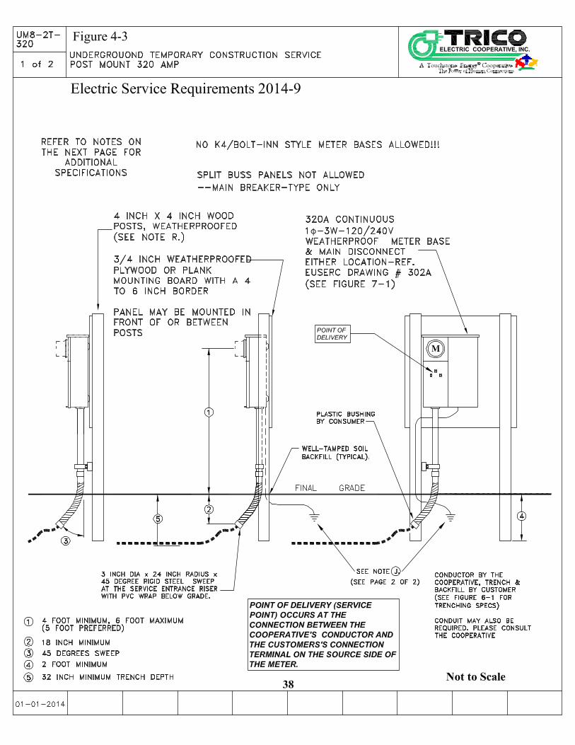
Figure 4-1, Figure 4-2 and Figure 4-3 show typical installations for overhead and
underground temporary construction service. Figure 7-3, can also be used for a
temporary installation. Standards for this type of structure must be met before the
Cooperative can provide service. All notes on these installation pages must be
followed. The Cooperative has the right to refuse connection if height, strength
bracing, or other requirements are not met.
1. To ensure strength, post must be free of any sucker knobs and have spike knots no larger than 1/3 of any face, cracks greater than 1/2 inch wide are not permitted, and no visible wood decay is allowed.
2 Figure 4-1 (Overhead Temporary Construction Service Pole) must be pressure or thermally treated with an approved American Wood Preservatives Association standardized preservative.
3. Distance between the Cooperatives’s point of attachment and the temporary service pole location, Figure 4-1, must be a minimum of 10 feet from the outside phase conductor and a maximum distance of 15 feet from the Cooperatives power source. The Customer must provide, out of the weatherhead, sufficient conductor for a drip loop and to be connected by the Cooperative to the power source. If the service length outside of these parameters requires additional facilities, the Cooperative shall furnish and install the pole(s) at the customer’s expense.
4. Distance between the Cooperative’s point of attachment and the temporary post-mounted underground service (Figure 4-2) should be within 10 feet of the power source, padmounted transformer, pedestal or handhole). If Customer supplies the conductor they must tail their own wire out of meter base with enough make up to be connected in transformer, pedestal or

Electric Service Requirements 2014-9
33
handhole.
5. A service conductor that crosses a driveway or road is required by the NEC and NESC to have a higher clearance above ground. See Table 5-1 for additional clearance requirements.
6. Soil surrounding post must be tamped to provide stability.
7. The local AHJ may require the grounding connection to be visible when electrical inspection is made. However, for safety reasons, top of ground rod should be flush with or below ground level.


Electric Service Requirements 2014-9
40
This Page Left Intentionally Blank

Electric Service Requirements 2014-9
41
5. Clearances
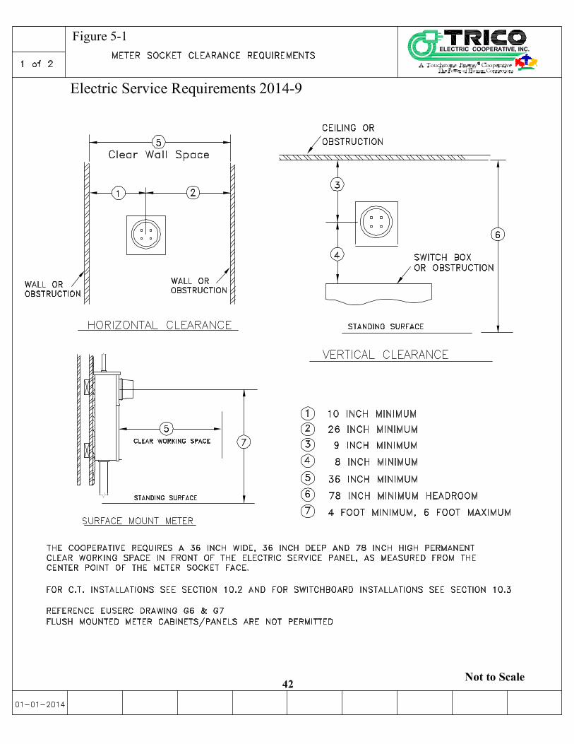
5.1. Meter Clearances and Locations
The Customer must provide suitable space and provisions for mounting a meter base at a
location acceptable to the Cooperative. It is in the mutual interest of both the Customer
and the Cooperative to provide a suitable location resulting in the most convenience to
both parties for reading, testing, and replacing meters. The minimum unobstructed
working space required by the Cooperative in front of a single meter is 36 inches wide, 36
inches deep and 78 inches high, (see Figures 5-1 and 5-2). The use of current
transformers requires a minimum working space of 78 inches high, 84 inches wide and
48 inches deep. Meters or current transformers installed in cabinets require a minimum
space of 48 inches deep to open the cabinet doors to 90 degrees. Place all meters and
metering equipment at least 36 inches from a gas meter or regulator vent.
Install residential meters outdoors at a location acceptable to the Cooperative. Generally
locate the meter on the side of the structure closest to Cooperative lines or within 10 feet
of the front (street) side to prevent meters from being located behind yard fences. Avoid
installations on exterior bedroom or bathroom walls or patios as well as exterior walls that
are likely to be fenced in. Never install the meter over window wells, steps in stairways, or
in other unsafe or inconvenient locations. Keep shrubs and landscaping from obstructing
access to meter.
Place nonresidential meters and all associated main electric service boxes outdoors unless
the Cooperative confirms prior to installation that no acceptable outdoor location exists.
Any indoor location must have prior written approval by the Cooperative. Make all meter
locations accessible to the Cooperative during daytime working hours (6:00 a.m. to 6:00
p.m.). Do not locate indoor meters in show windows, closets, bathrooms, over sinks or
laundry tubs, or in any location not safe, convenient, or readily accessible. Locked meter
rooms are not considered to be accessible unless keyed for a Cooperative lock or equipped
with a Cooperative-provided lock box for each meter room. For entry ways to meter
rooms, doors must open outward.
For meter sockets located outdoors, install so that the center of the socket is no higher than
6 feet and no lower than 4 feet above the finished grade or floor immediately in front of
the meter, except for the center of meter sockets in pedestals which are set for 42"
minimum above finished grade. In the case of vertical four-gang meter bases, set the
center of the lowest meter socket to no less than 42 inches above final grade.
If a Customer makes a meter inaccessible (in the opinion of the Cooperative) such as by
installing a fence or enclosure, the Customer must, at his or her own expense, provide
access acceptable to the Cooperative or move the meter socket to a location acceptable to
the Cooperative.
The Cooperative will not install meters on mobile structures such as trailers, barges,
cranes, dredges, draglines, or any mobile pumping equipment or on floating dwelling
units such as houseboats.


Electric Service Requirements 2014-9
46
Table 5-1 Minimum Clearances for Service Drops
(600 Volt and Below)
Loaded Conditions
Minimum service drop clearance
• Over roads, streets, and other areas subject to truck traffic. . . . . . . . . . . . . . . . . . . . . . . . . . . . . 16 Feet
• Over or along alleys, parking lots, and nonresidential driveways. . . . . . . . . . . . . . . . . . . . . . . .16 Feet
• Over land traveled by vehicles. . . . . . . . . . . . . . . . . . . . . . . . . . . . . . . . . . . . . . . . . . . . . . . . . . 16 Feet
Minimum clearances over or along residential driveways
• If height of attachment will permit. . . . . . . . . . . . . . . . . . . . . . . . . . . . . . . . . . . . . . . . . . . . . . 16 Feet
• If not;
For service drops 120/240 & 120/208Y volt, provided trucks are not anticipated. … … 12.0 Feet
The Cooperative does not allow buildings or structures to be placed under Cooperative facilities. Per this document, no
vertical clearance over buildings or structures is stated. If structures are built under a line that was constructed after
the issuance of this document, 2014, all expense to relocate the structure or Cooperative facilities will be borne by the
Customer.
Minimum clearances from buildings for service drops not attached to the building
• Vertical clearance over or under balconies and roofs-Prior to the 2014 issuance of this document!
All Areas . . . . . . . . . . . . . . . . . . . . . . . . . . . . . . . . . . . . . . . . . . . . . . . . . . . . . . . . . . . 11 Feet
• Horizontal clearance to walls, projections, windows, balconies, and areas accessible to pedestrians
If cabled together with grounded bare neutral. . . . . . . . . . . . . . . . . . . . . . . . . . . . . . . . . . . . 5 Feet
If open wire or cabled with an insulated neutral. . . . . . . . . . . . . . . . . . . . . . . . . . . . . . . . . . 5.5 Feet
Minimum clearances for service drops attached to a building or other installation (over or along the installation to
which they are attached)
• From the highest point of roofs, decks or balconies over which they pass-Prior to the 2014 issuance of this
document!
All Areas . . . . . . . . . . . . . . . . . . . . . . . . . . . . . . . . . . . . . . . . . . . . . . . . . . . . . . . . . . . . 11 Feet
Above a not-readily-accessible roof and terminating at a (through-the roof)
service conduit or approved support, the service and its drip loops set not less
than 1 8-inches above the roof. Not more than 6-feet of the service cable
over the roof or within 4-feet of the roof edge. . . . . . . . . . . . . . . . . . . . . . . . . . . . . . 1.5 Feet
In any direction from windows designed to open (except from above) . . . . . . . . . . . . . . . . 3 Feet
In any direction from doors, porches, fire escape, etc . . . . . . . . . . . . . . . . . . . . . . . . . . . . . . 3 Feet
Minimum clearances for drip loops only limited to 150 volts to ground. . . . . . . . . . . . . . . . . . . . . . . 10 Feet

Electric Service Requirements 2014-9
47
5.1.1 Definition Notes for Clearance Table 5-1
1. A truck is any vehicle exceeding 8 feet in height. Areas not subject to truck
traffic include places where truck traffic normally never occurs or is not
reasonably anticipated.
2. Spaces and ways subject to pedestrians or restricted traffic only include those
areas prohibiting equestrians, vehicles, or other mobile units that exceed 8 feet
in height, through regulations, by permanent terrain configurations, or not
normally encountered or reasonably anticipated.
3. The Cooperative considers a roof, balcony, or area to be readily accessible to
pedestrians if it can be casually accessed through a doorway, ramp, window,
stairway, or permanently-mounted ladder, by a person on foot who neither
exerts extraordinary physical effort nor employs special tools or devices to
gain entry. The Cooperative does not consider a permanently mounted ladder
as a means of access if its bottom rung is eight feet or more from the ground
or other permanently-installed accessible surface.
5.2 Clearances from Pools, Spas or Hot Tubs
5.2.1 Overhead Clearances
Overhead conductors shall not be located within 10 feet horizontally of a pool or
pool attachments (NEC 680-8). The Cooperative recommends conductors not pass
over pools, buildings, trees, or other obstructions. Consult the Cooperative before
construction.
5.2.2 Underground Clearances
NEVER locate underground conductors under or horizontally within 5 feet (NEC
680-10) of the inside wall of a pool or spa. The Cooperative installed conductors
must be in conduit (electric grade gray Schedule 40 PVC) installed by the
Customer. For trench depth, cover, and conduit requirements see section 6.
5.3 Clearance from Underground Gasoline Storage Tanks
Underground service conduits shall be located at least 10 feet from the fill opening of
underground tanks containing flammable liquids. Where the fill opening is a tight
connection, a 5 foot distance shall be maintained. Consult the Cooperative before
construction.
5.4 Clearance from Padmounted Transformer
Figure 5-4, Padmounted Transformer Clearance, located on the next page, shows
appropriate clearances from padmounted transformers.


Electric Service Requirements 2014-9
49
This Page Left Intentionally Blank

Electric Service Requirements 2014-9
50
6. Underground Requirements
6.1 Underground Service
The Customer will have the responsibility for the trenching, shading, backfilling, and
compaction of Customer provided trenches. The Customer shall install conduit,
basements, concrete products such as vaults and certain pads, and any other
requirements to complete the construction for underground service. Any conduit
installed by the Customer must be inspected prior to backfill, contact the Operations
Department to schedule an inspection. The Customer shall be responsible for any
problems associated with the conduit installation, until such time the Cooperative has
installed its facilities.
Conduit is required under any paved areas. Refer to the Table 6-1 Minimum Conduit Required for Utility Conductors for the minimum conduit acceptable for Cooperative
service lateral conductors to be installed.
Where exposed to motorized vehicles, the customer must install and maintain
Cooperative approved barriers to protect padmounted transformers and other equipment.
(See Figure 6.3)
The Cooperative will install, maintain, and own the underground service lateral from the
Cooperative's distribution line or transformer to the point of delivery (POD), except as
noted in the next paragraph.
The Customer is required to install and own secondary underground services for any
installation that requires Current Transformer (C.T.) metering. This includes
commercial services over 200 amperes, residential single phase services over 400
amperes, (320 amperes continuous) and three phase services over 200 amperes.
Where underground services are CT metered, the point of delivery (POD) shall be the
point in the circuit at which the transformer secondary conductors exit the Cooperative
provided terminations. While ownership of the secondary conductors transfers from the
Cooperative to the Customer at the (POD), the Customer is responsible for purchasing
and installing a continuous length of secondary cable necessary to allow connection to
the transformer secondary terminals. The Cooperative retains exclusive responsibility
for connection of secondary service conductors to the transformer and for oversight of all
work activities within the transformer basement and/or transformer secondary
termination cabinet.

Electric Service Requirements 2014-9
51
6.2 Trenches Provided by the Customer
To comply with OSHA rules and the Cooperative standards when not shoring the
trench, keep the excavated soil at least two feet away from the open trench.
The location of the service entrance on the Customer's premises is an important
consideration to both the Customer and Cooperative. Customer responsibilities include:
� Consulting the Cooperative to determine the route and the point of attachment for underground service laterals, meter locations, service stub-out locations, current transformers, and terminal cabinet enclosures. Routing conduit under buildings or other permanent obstructions shall not be allowed.
� Locating the service entrance to make the meter and service easily accessible from Cooperative distribution lines and convenient for the installation, operation, and maintenance of Cooperative meters and equipment.
The Customer is responsible to recognize potential surface and sub grade water flows and coordinate with the Cooperative to minimize potential run-off problems.
6.2.1 Call Before You Dig
State law requires the Customer/Excavator to call for underground utility cable locates at least two full working days (48 hours) prior to excavation. The excavation must not be started until locates have been marked or the utilities have informed the excavator that they have no facilities in the area. Call 1-800-STAKE IT (782-5348) or 811 before you dig.
State Overhead Power line Safety law also requires that if you will be working within close proximity of an energized overhead line, the Cooperative must be notified and appropriate steps taken prior to commencement of any work.
6.2.2 Backfill
The Customer will be responsible for backfilling trenches they provide. The Customer must follow the Cooperative’s backfill standards and associated specifications. See Figure 6.1. Contact the Cooperative office for the backfill procedure to be used. The Cooperative will NOT energize conductors until the Customer completes backfill to the Cooperative’s satisfaction.
6.2.3 Service Trench
When installing only service cable in the trench, follow "Secondary Trench Detail UR2-32" in Figure 6-1. When installing service cable with other utilities there is a 12 inch minimum separation from surface to surface required. Please contact the other utilities to verify their depth and separation requirements.
6.2.4 Primary Trench
Primary trench requirements may vary consult the Cooperative for trench

Electric Service Requirements 2014-9
52
requirements before installation. When trenching for Primary Conductor installation,
refer to Figure 6-1 “Main Trench Detail Spec UR2-54”. The Customer may place
communication, signal and other electrical conductors in the same trench as the
Cooperative conductors, provided that the installation meets Cooperative
specifications, all applicable code requirements are met and all concerned parties
agree on such placement.
The Cooperative will not install Primary electrical conductors in a common trench
with sewer unless unusual conditions such as adverse soil or route restrictions exist.
The Customer must make a request to the Cooperative in writing for any
deviation from this standard, and supply all supporting documentation. All
such installations require the prior approval of the Cooperative and other utility
involved.
Backfill material shall be 1 ½ inch minus in size for the first 14 inches of backfill. It
can be screened spoil material or imported sand or pea gravel. Shaded backfill shall
be 2 inches below and 12 inches above the conduit or cable. The remainder of the
trench backfill shall be free of rocks larger than 4 inches diameter.
When providing trench, the Customer will be responsible for backfilling trenches and
site restoration.
The Cooperative will NOT energize conductors until the Customer completes
backfill to Cooperative’s satisfaction
The Customer shall hand dig within 2 feet of Blue Stake marks. When nearing a
transformer or secondary junction box the Customer shall contact the Cooperative to
assist with installation of conduit sweeps.


Electric Service Requirements 2014-9
57
This Page Left Intentionally Blank

Electric Service Requirements 2014-9
58
This Page Left Intentionally Blank

Electric Service Requirements 2014-9
59
6.3 Conduit
When pre-approved to install conduit, the Customer shall install electrical-grade Schedule
40 gray PVC as acceptable conduit. DB-120 conduit may be allowed in certain conditions,
but Schedule 40 sweeps are still required. Note, Figure 7-2 & 7-3 do allow for a DB-120
sweeps, though these are the exceptions. If rock or other obstructions are encountered
consult the Cooperative. When the conduit terminates at a Cooperative pole, consult the
Cooperative for exact conduit size and correct quadrant position on the pole and to
determine if a UK5 Power Pedestal is planned. If so refer to Figure 6-2.
If service being constructed is within a duly recorded subdivision, contact the
Cooperative for details regarding that specific subdivision’s conduit requirements as
they may be different. For all other installations, table 6-1 shows minimum conduit
requirements.
Table 6-1 Minimum Conduit Required for Utility Conductors
Secondary Voltage (Under 600 V)
This table is to be used typically for up to three bends, 270 degrees or less, and
generally less than 150 feet of conduit (see note E.): This Table is not for a
conduit sleeve. For sleeve, refer to Figure 6.1
Service Entrance
Ampacity
Single phase Three Wire
Three phase Four Wire
200 or Less
201 - 400
401 - Up
One 2 1/2 inch (see note)
One 3 inch
Consult Electrical Eng.
One 3 inch
Consult Electrical Eng.
Consult Electrical Eng.
A. Larger conduit size or bend radius may be required for longer runs, more bends, four-wire
full neutral, or direct connection to utility conduit. Customer shall consult the
Cooperative for specific requirements.
B. See underground requirements for normal trench depth. Depth at sweep may be
deeper depending upon how and where conduit terminates. See Figure 6-2 & 7-2
for typical termination points.
C. Customer's service conductors must be in a separate conduit system from the Cooperative conductors.
D. To properly select wire and conduit size, the Cooperative must take into consideration customer load, customer service equipment, and service length.
E. Secondary elbows must be schedule 40 and have a minimum 24 inch sweep radius. All bends must be factory made.
F. Customer installed conduit runs containing more than 360 degrees of bends must be approved by the Cooperative before installation. If approved, the elbows must be encased
Notes:

Electric Service Requirements 2014-9
60
in a minimum of 3 inches and a maximum of 5 inches of concrete. Concrete protection shall have a strength of 1500 to 2500 lbs. per square inch with a minimum slump value of 7 and a maximum of 8. Aggregate should be small, generally half inch or less to flow readily between ducts. The concrete encasement must extend a minimum of 12 inches past the joints.
G. Mule tape or flat poly rope capable of withstanding 1,250 lbs. of tension shall be provided by the Customer with 6 feet of line extending from each end of the conduit. The pull line must be one continuous piece. The tying of short pieces together to make up the full run is not allowed. The pull line shall be installed after conduit is jointed and glue is dry.
H. The Cooperative will not install conductors in a conduit if the conduit system is improperly constructed. The Customer is responsible to proof (mandrel) all conduit he has installed in the presence of the Cooperative’s Inspector.
I. The use of conduit reducers such as the swedge coupling, are not allowed anywhere in the conduit system.
6.4 Concrete Pads and Vaults for Padmounted Equipment
All concrete equipment pads, boxpads and vaults to be supplied and installed by the
Customer when required by the Cooperative.
6.4.1 Barrier Post
Install 4 inch diameter steel, concrete-filled barrier post(s) around the Cooperative
equipment in areas where the equipment is exposed to vehicle traffic. For additional
specifications and other options contact the Cooperative office. See Figure 6.3
Equipment Barrier for further Details .


Electric Service Requirements 2014-9
62
This Page Left Intentionally Blank

Electric Service Requirements 2014-9
63
7. Single Family Service
7.1 General
The location of the service entrance on the Customer’s premises is an important
consideration. For clearance and location information see section 5 (Clearances).
• Consult the Cooperative to determine the point of attachment for overhead service
drops, underground service laterals, and meter locations.
• Position the service entrance and meter to make them more accessible from
Cooperative distribution lines and convenient for the installation, reading, and
maintenance of Cooperative meters.
The Customer will provide, install, and maintain all service equipment (including service
entrance conductors for overhead services, enclosures, and meter sockets) to include rights-
of-way and space for the installation and maintenance of the Cooperative facilities. Some
conditions include:
• The Customer must not terminate the principal grounding conductor in the
Cooperative's sealed termination compartment.
• Customer wires installed in meter bases must allow clear space for the installation
of Cooperative wires. Panel covers must be secured prior to energizing.
• See section 6 for underground and conduit requirements.
• The meter socket must not be used as a junction box.
Always use ring-type meter sockets, complete with a company approved sealable ring.
7.1.1 Residential Sockets
Single phase self-contained residential sockets which have maximum current
capacity of 200 and 400 amperes (320 amperes non-continuous) and are ANSI,
UL, EUSERC, and Cooperative approved may be used. Services rated less than
200 amperes require prior approval by the Cooperative to allow for proper
conductor and conduit size. Follow approved EUSERC drawings # 301 & 301A
(200 amp maximum single phase) and EUSERC drawings # 302A (400 amp
maximum (320) amp continuous) single phase. Ring-less meter sockets by
Cooperative approval only. See Figure 7-1.
Code calculated loads greater than 320 amperes require current transformer
metering. Refer to Section 10.2 for requirements.

Electric Service Requirements 2014-9
64
7.2 Underground Service
Before preparation of underground service, the Customer must obtain approval and
specifications from the Cooperative covering the proposed installation and the Customer’s
responsibilities.
The Customer is responsible to recognize potential surface and sub grade water flows and
coordinate with Cooperative to minimize potential run-off problems.
Customers adequately served by existing overhead distribution facilities, but desiring
underground service, should contact the Cooperative for details of the Cooperative policy
for conversions. Special rules may apply in core areas of cities where local ordinances
specify underground service.
7.2.1 Underground Service Extension
Figures 7-2, 7-4 & 7-5 show typical installations of underground service
extensions from a transformer or secondary pedestal to a house. See Section 6.3
for conduit requirements.


Electric Service Requirements 2014-9
73
This Page Left Intentionally Blank
Electric Service Requirements 2014-9
74
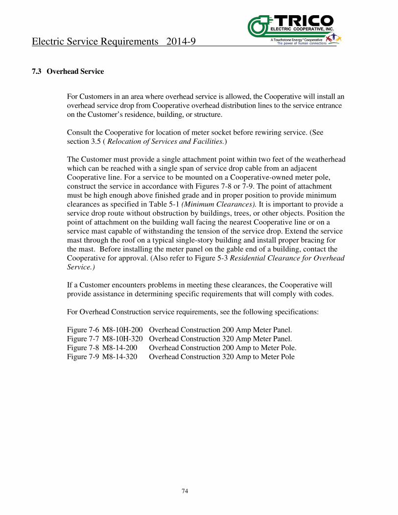
7.3 Overhead Service
For Customers in an area where overhead service is allowed, the Cooperative will install an
overhead service drop from Cooperative overhead distribution lines to the service entrance
on the Customer’s residence, building, or structure.
Consult the Cooperative for location of meter socket before rewiring service. (See
section 3.5 ( Relocation of Services and Facilities.)
The Customer must provide a single attachment point within two feet of the weatherhead
which can be reached with a single span of service drop cable from an adjacent
Cooperative line. For a service to be mounted on a Cooperative-owned meter pole,
construct the service in accordance with Figures 7-8 or 7-9. The point of attachment
must be high enough above finished grade and in proper position to provide minimum
clearances as specified in Table 5-1 (Minimum Clearances). It is important to provide a
service drop route without obstruction by buildings, trees, or other objects. Position the
point of attachment on the building wall facing the nearest Cooperative line or on a
service mast capable of withstanding the tension of the service drop. Extend the service
mast through the roof on a typical single-story building and install proper bracing for
the mast. Before installing the meter panel on the gable end of a building, contact the
Cooperative for approval. (Also refer to Figure 5-3 Residential Clearance for Overhead
Service.)
If a Customer encounters problems in meeting these clearances, the Cooperative will
provide assistance in determining specific requirements that will comply with codes.
For Overhead Construction service requirements, see the following specifications:
Figure 7-6 M8-10H-200 Overhead Construction 200 Amp Meter Panel.
Figure 7-7 M8-10H-320 Overhead Construction 320 Amp Meter Panel.
Figure 7-8 M8-14-200 Overhead Construction 200 Amp to Meter Pole.
Figure 7-9 M8-14-320 Overhead Construction 320 Amp to Meter Pole


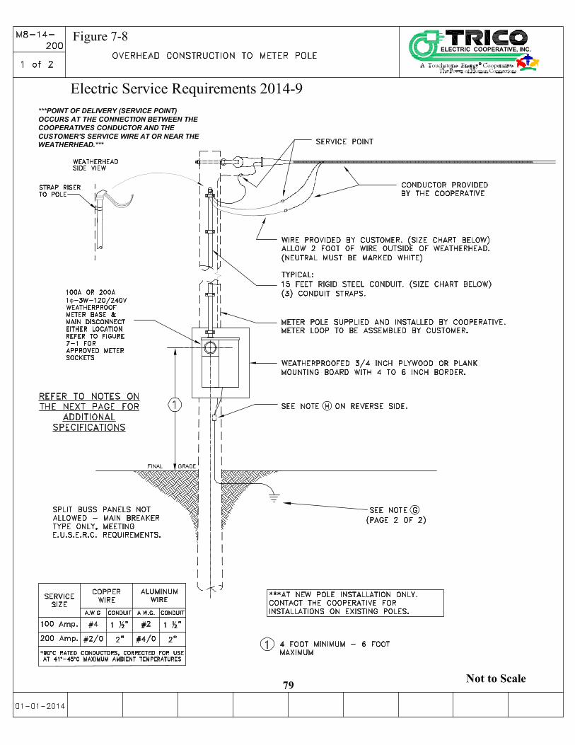


Electric Service Requirements 2014-9
83
This Page Left Intentionally Blank

Electric Service Requirements 2014-9
84
8. Multiple Family Service
8.1 General
This section describes grouped service locations that provide separate metered services,
for multi-family units, such as duplexes or apartments. The Cooperative requires grouping of service entrances at a common location.
8.2 Underground Service
Conduit is preferred for multiple family underground services. Refer to section 6 for
underground and conduit requirements. See Figure 8-1 for typical Multiple Meter
Socket installations
8.3 Overhead Service
The Customer is responsible to bring service entrance conductors from the service
head to the Cooperative’s point of attachment. The Cooperative will not extend
conductors from the point of attachment to individual service heads.. Only in
extreme situations should the Customer consider overhead service to Multi-Family
installations. Consult the Cooperative if you are planning Overhead Service for this
application.
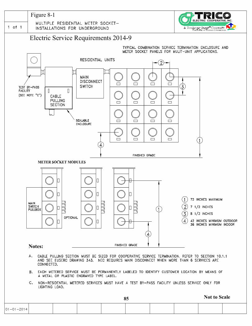

Electric Service Requirements 2014-9
86
This Page Left Intentionally Blank

Electric Service Requirements 2014-9
87
9. Manufactured and Mobile Home Service
9.1 Underground Service Information
Refer to section 6 (Underground Requirements) and to Figures 4-2, 4-3 & 7-3 for
requirements that pertain to installation of underground secondary (less than 600 volts)
service.
9.2 Underground Service to Manufactured Homes Sockets
Underground service to manufactured homes will be provided under the same requirements as
single-family service (see section 7 Single Family Service), because the home is site specific, occupies a private lot, and the service entrance is factory built with the construction of the home.. Keep in mind the meter height and position requirements in section 5.1 (Meter Clearances and Locations). When the meter socket is improperly located, the Customer is responsible for
all modifications to relocate or locate the meter to Cooperative requirements.
9.3 Underground Service to Mobile Homes
For underground service to a mobile home, locate the Customer's service entrance equipment
either in an approved pedestal, (see Figure 7-3) or mount on wood posts (see Figure 4-3). The
Customer must furnish, install, and maintain the pedestal or wood posts. The bottom of the
enclosure containing the service equipment should be not less than 24 inches above the
finished grade. For a meter subject to physical damage, the Customer must install and
maintain barrier posts or other suitable protection approved by the Cooperative (see barrier
post requirements Figure 6.3). Mobile home pedestals shall be installed a minimum of 3 feet
from the home.
After approval, the Cooperative will provide service to the meter pedestal for permanent
metered service to mobile homes located in parks. Each mobile home must have a separate
meter pedestal service approved by the Cooperative for termination of the Cooperative's
service conductors.
Position Cooperative conductor trenches and conduit, per the Cooperative’s design plan, in
mobile home parks away from the pad (never underneath), foundation, or area provided for
the manufactured home.
9.4 Installation of Pedestal and Post Meters for Underground Service
Refer to Figure 7-3 and Figure 4-3 for underground metered services installed for a mobile
home.
9.5 Overhead Service Information
The Cooperative will supply new overhead service to any building or premises except in
an area designated by local government jurisdiction and/or the Cooperative as an
underground district, restricted to underground service.
Refer to section 7 (Overhead Service) for service drop information.

Electric Service Requirements 2014-9
88
9.6 Overhead Service to Manufactured Homes
The Cooperative will provide overhead service to manufactured homes using the same
requirements as residential occupancies listed in Section 7.3 (Overhead Service) because the home is site specific, occupies a private lot, and the service entrance is factory built with the construction of the home.
The Customer must make provision for meter height and placement as described in Section
5.1 (Location of Meters). When the meter socket is improperly located the Customer is
responsible for all modifications to relocate or locate meter to Cooperative requirements.
9.7 Overhead Service to Mobile Homes
The Customer must install the meter base and service equipment on a Cooperative owned
wood pole. See Figure 7-8, or Figure 7-9 for Overhead Construction to a Meter Pole in
Section 7.3.

Electric Service Requirements 2014-9
89
This Page Left Intentionally Blank

Electric Service Requirements 2014-9
90
10. Commercial, Industrial, Agricultural Services
This section describes the Cooperative requirements for commercial, industrial, and
agricultural services. This section covers single phase and three phase services for self-
contained and current transformer type metering. The Customer is responsible to
coordinate service requirements with the Cooperative before purchase of material and
installation.
All commercial, industrial, or agricultural customers must coordinate their service
requirements with the Cooperative before purchase and installation of equipment.
Single phase and three phase services over 200 amps require current transformer (C.T.)
metering. For all services that require C.T. metering, the customer shall provide, install and own the secondary conductor and conduit (see paragraph 6.1 in section 6.0 Underground Requirements for additional important information regarding transfer of ownership at the point of delivery). The customer shall terminate the
secondary conductor on the line and load side of the C.T. The Cooperative shall provide,
install and own the C.T.'s. The Cooperative shall terminate the secondary conductors in
the transformer. The Customer shall coordinate with the Cooperative to schedule the
termination of the secondary conductor in the transformer. The Cooperative shall wire,
own and operate meter wiring from the C.T.'s to the meter. The Cooperative shall also
install and own the meter.
Primary service refers to delivery at greater than 600 volts. The Cooperative must be
consulted before installation of primary service.
The Customer must not terminate the principal grounding conductor in the Cooperative's
sealed termination compartment.
10.1 Self-contained Metering
The Cooperative requires a self-contained safety socket-type meter when the
ampacity of a single phase or three phase service is 200 amperes continuous or less.
Refer to Figure 10-1 for approved meter sockets.
Limit the continuous duty on self-contained meter sockets for motor loads to:
• 60 hp at 208Y/120-volt, three phase.
• 125 hp at 480Y/277-volt three phase
Motor sizes above these horsepower values will be metered with current
transformers (see Section 10.6)


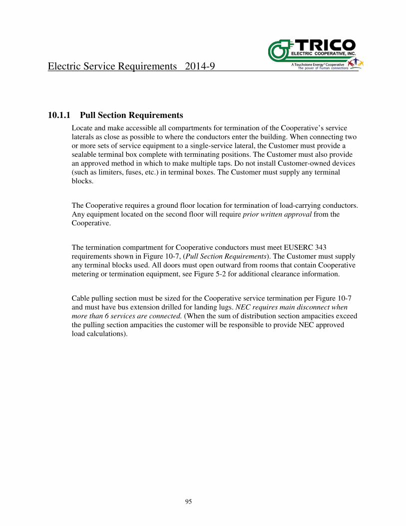
Electric Service Requirements 2014-9
95
10.1.1 Pull Section Requirements
Locate and make accessible all compartments for termination of the Cooperative’s service
laterals as close as possible to where the conductors enter the building. When connecting two
or more sets of service equipment to a single-service lateral, the Customer must provide a
sealable terminal box complete with terminating positions. The Customer must also provide
an approved method in which to make multiple taps. Do not install Customer-owned devices
(such as limiters, fuses, etc.) in terminal boxes. The Customer must supply any terminal
blocks.
The Cooperative requires a ground floor location for termination of load-carrying conductors.
Any equipment located on the second floor will require prior written approval from the
Cooperative.
The termination compartment for Cooperative conductors must meet EUSERC 343
requirements shown in Figure 10-7, (Pull Section Requirements). The Customer must supply
any terminal blocks used. All doors must open outward from rooms that contain Cooperative
metering or termination equipment, see Figure 5-2 for additional clearance information.
Cable pulling section must be sized for the Cooperative service termination per Figure 10-7
and must have bus extension drilled for landing lugs. NEC requires main disconnect when
more than 6 services are connected. (When the sum of distribution section ampacities exceed
the pulling section ampacities the customer will be responsible to provide NEC approved
load calculations).


Electric Service Requirements 2014-9
97
10.2 Current Transformer Metering
Current transformer (C.T.) metering is required when a three phase service exceeds 200
amperes, when a single phase commercial service exceeds 200 amperes, or when a single
phase residential service is greater than 400 amperes ( 320 amperes continuous). For all
services that require C.T. metering, the customer shall provide, own, and install the
secondary conductor and conduit.
It is preferred that the C.T. Can/Cabinet and meter socket be mounted outside of the building
within 50 feet of the transformer. Where metering equipment is installed in a location where
it might be struck by a motorized vehicle, the Customer is to install and maintain a
Cooperative approved barrier post. Refer to Figure 6.3
If access to metering requires entrance into a building, a lockbox and key shall be provided
by and installed by the customer.
10.2.1 The Customer will provide and install:
• Provide, own, and install line and load side service conductors on the current
transformer mounting base. Provide, own, and install a weather tight NEMA 3R
rated metallic cabinet securely mounted on a rigid surface. The door is to be hinged
and capable of being sealed. The cabinet is to be sized in accordance with Table 10-
3, Current Transformer Cabinet.
• Current transformer mounting base, meeting EUSERC requirements and rated to the
applicable ampere fault duty. See Figures 10-13 & 10-14.
• The meter socket enclosure drilled and tapped for a Cooperative test switch. See
Figure 10-8 for approved sockets.
• The conduit between the meter socket enclosure and current transformer mounting
base.
• Barrier post (4 inch diameter) required where metering equipment is installed in
vehicle traffic area. Refer to Figure 6.3.
• Grounding must meet applicable requirements of the local AHJ or in absence of an
AHJ, NEC requirements. Lugs for terminating the Customer's ground wire (or other
grounding conductors) shall be located outside of the sealable section. See Figure
10-15 for a grounding and bonding guide.
• Both the current transformer cabinet and meter socket must be mounted plumb in
both directions.
• See Section 5 for required clearances.
10.2.2 The Cooperative will:
• Provide, own, and install the meter, current transformers and test switch, with their
associated wiring. The test switch will be provided and installed by the Cooperative.
Note: Cooperative equipment shall not be located higher than the C. T. cans to minimize
water drainage into the customers' equipment.

Electric Service Requirements 2014-9
98
10.2.3 Current Transformer Metering Conduit
The Customer must provide conduit between meter socket and the current transformer cabinet.
Use the following guidelines to install the conduit:
• Rigid 1 inch diameter galvanized steel conduit shall be used. Conduits shall have
proper fittings and bushings when entering enclosures to protect metering
conductors.
• Conduit must be of sufficient length to insure a minimum distance of 10 inches
between the center of the meter socket and the current transformer cabinet. The
conduit should not exceed 12 inches in length.
If the standard location is not suitable or workable, an alternate location may be approved. Any
alternate location must have prior written Cooperative approval and must adhere to the following
guidelines:
• Conduit runs shall be 50 feet or less, with no more than three bends totaling 270°. No one
bend greater than 90° will be allowed. Runs longer than 50 feet must be approved by the
Cooperative.
• Pull lines are required in all conduits as specified in table 6-1 note G.
• Use rigid steel (1 inch diameter minimum). EMT conduit will be allowed for runs less than
10 feet.
• Secure all removable conduit fittings with ¼ inch x #20 metal screws with sealing provisions.
(LB's are not allowed outside the enclosure without prior written Cooperative approval.)
10.2.4 Current Transformer Cabinets
• Only conductors associated with metering shall be permitted in the current transformer
enclosure. No connections shall be made in any current transformer enclosure to supply any
other meter.
• The Customer conductors shall exit the enclosure on the load side of the current
transformers. Any proposed change to this must be approved by the Cooperative. For
other underground service applications, a separate terminating pull box will be provided for
the Cooperative service lateral. See Figure 10-7 for pull box requirements.
• The cabinet must be mounted in a readily accessible location acceptable to the Cooperative.
Current transformers shall be installed by the Cooperative.
• The top of the C.T. mounting bracket shall not be more than 6 feet above floor level. The
cover shall have factory installed hinges for side opening with sealing provisions and shall be
able to hold the cover in the open position at 90° or more. Refer to Figure 10-9 for additional
information.
• The Customer will connect conductors to the line and load-side of the mounting base, see
Figures 10-13 and 10-14. Line and load-side terminations on C.T. landing pads require two
bolts per connector.


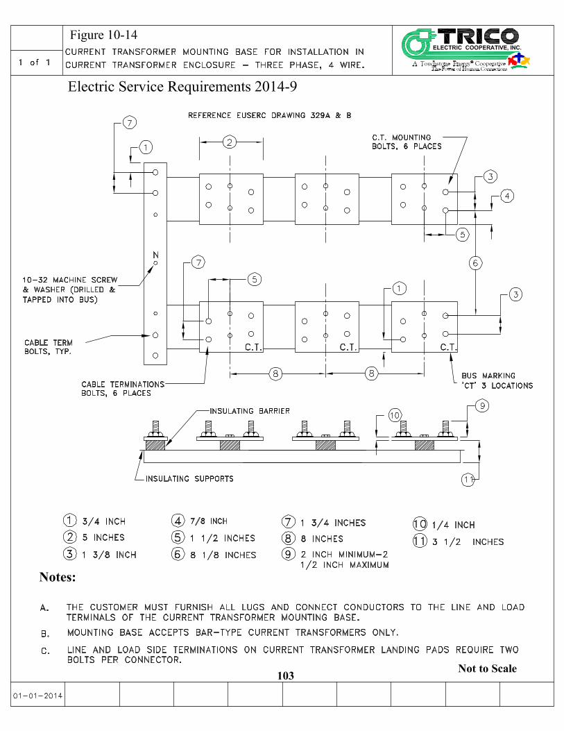


Electric Service Requirements 2014-9
105
This Page Left Intentionally Blank

Electric Service Requirements 2014-9
106
10.3 Switchboard Metering
A switchboard metering section, meeting EUSERC requirements, should be used
when the service entrance rating is greater than 800 amperes. Switchboard metering
sections may also be used for three phase services over 200 amperes and single phase
service over 320 amperes. See Figure 10-16 for general switchboard information.
All switchboard service entrance plans and site plans shall be submitted by the
Customer to the Cooperative for approval by the Cooperative prior to the Customer
constructing the switchboard. Switchboard plans and diagrams submitted for approval
shall show and detail all proposed service entrance conductor pull and landing
sections, current transformer section, and meter socket and meter test switch doors or
sections.
The instrument transformer compartment shall be completely separated by a rigid
barrier from the rest of the switchboard. It shall have hinged doors which are sealable
with pad lock type sealing devices. It shall be large enough to contain the required
number of through-type current transformers. The design shall be such that the
transformers can be readily installed or changed after the switchboard is in place.
Removable sections of bus bar shall be provided as the primary conductor of the
current transformers, and shall be the same ampacity as the bus bar entering and
exiting the compartment.
If the Cooperative approves the submitted switchboard plans, the Cooperative shall
provide to the Customer written notice of such approval.
The Cooperative will not accept or provide electric service to switchboard service
entrance gear unless the Customer has received approval of submitted plans from the
Cooperative.
The metering current transformers shall be located in the current transformer
compartment. The meter socket and test switch may be mounted within the
switchboard on an exposed panel face or remotely. It is preferred by the Cooperative
that the switchboard and metering be located on the outside of the building and the
service entrance conductor section, the current transformer section and the metering
section be housed within the main switchboard assembly. If the Switchboard is
located within a building it is preferred that it be located in an electrical room that
limits access to unqualified persons. If the metering socket and meter test switch are
not housed on or within the switchboard, a remote meter shall be mounted on the
exterior of the switchboard, (see Figure 10-18). A remote meter can be installed on the
exterior of the building, with the switchboard located inside the building, if agreed
upon by the Cooperative. Under no circumstances shall the linear length of metering
Electric Service Requirements 2014-9
107
conductors from the current transformer's to the meter be greater than 50 feet.
The Cooperative shall be given safe and unimpaired access at reasonable times to the
premises of the Customer for the purpose of reading meters, testing, repairing,
relocating, removing or exchanging any or all equipment or facilities necessary to
provide or remove electric service to the Customer. Immediate and unannounced
access may be necessary if the Cooperative has an outage or emergency condition.
The current transformer section shall be on the supply side of the main switch or
circuit breaker.
Mounting pad for all switchboard metering enclosures will be a minimum 4" thick
concrete pad.
10.3.1 Switchboard Service Termination
• The Customer will provide the switchboard section, instrument transformer
mounting base(s), panels, and meter socket, with provisions for a test switch.
• Meter and test switch are to be owned, provided, and installed by the
Cooperative at or near the Customer-owned metering compartment of the
switchboard. With a remote meter location, approved meter sockets shall
have provisions for a Cooperative installed a test switch, see Figure 10-8.
• Window or doughnut type current transformers for switchboards are
provided and installed by the Cooperative. Current Transformer line and
load side connections are to be installed by the Customer and electrical
connections are to be tightened to the switchgear manufacturers torque
specification. For underground service, the Customer will terminate the
service conductors on lug landings in the pull section.
• The Customer locking mechanism for the metering enclosure must provide for
independent access by the Cooperative.
• Terminating bolts must be secured in place and shall be provided with nuts,
flat washer, and a spring washer, and all parts must be resistive to corrosion.
Bus bars are required from the pull section into the service section.
• The Cooperative requires a minimum clear work space of 78 inches high by 36
inches minimum width by 48 inches deep in front of switchboards containing
metering equipment.
• Grounding must meet applicable requirements of the local AHJ or in absence
of an AHJ, NEC requirements. Terminals for terminating the Customer's
grounding conductors shall be located outside of the pull, service entrance,
current transformer, or meter socket & test switch sections. See Figure 10-
15 for a grounding and bonding guide.
• All switchboard removable panels and covers to the compartments or
sections containing unmetered conductors or bus, the current transformer
section and if applicable the metering section shall have provisions for the

Electric Service Requirements 2014-9
108
installation of a Cooperative sealing device .
• All pull and termination sections shall be full front access. Cover panels
shall be removable, sealable, provided with two lifting handles, and limited
to a maximum size of 9 square feet in area.
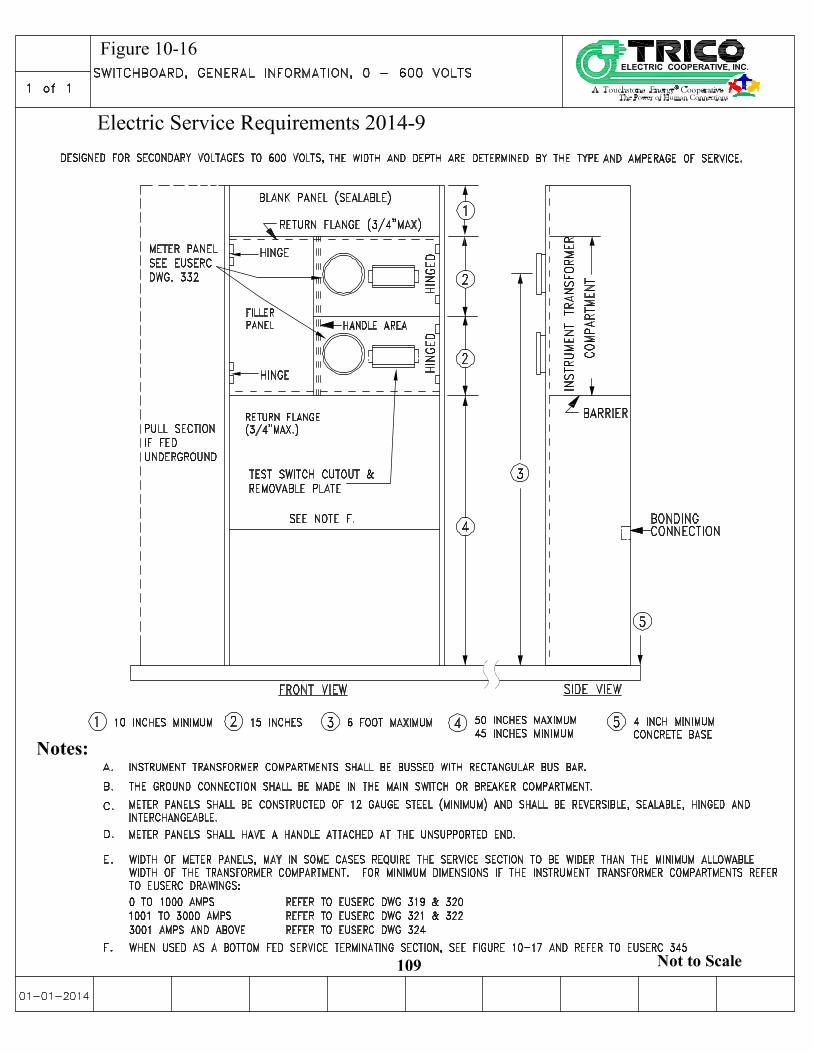


Electric Service Requirements 2014-9
114
10.4 Primary Voltage Service (Over 600 Volts)
10.4.1 General
High-voltage instrument transformers and transformer rated meters are
required for Customers taking service at primary voltage under provisions of
the Cooperative's rate schedule. To establish a mutually satisfactory
location for the Point of Delivery (POD) and metering details, the Customer
must consult the Cooperative before construction begins.
The Cooperative will provide primary voltage delivery to Customers
directly, in accordance with the Cooperatives Rules, Regulations and Line
Extension Policy, without transformation, from the high voltage or
"primary" distribution system standard for the location in which service is
requested.
10.4.2 Customer Equipment
The Customer receiving service at primary voltage may own poles,
conductors, cables, transformers, and associated protective devices in
accordance with the filed rate schedule or special contract. The Cooperative
reserves the right to approve of or require modification of the Customer’s
distribution system prior to installation.
10.4.3 Cooperative Equipment
The Cooperative will install a pole or a padmounted enclosure (both at
Customer expense), containing the primary metering equipment in
accordance with the current filed Rules, Regulations & Line Extension
Policy and rate schedule and, in addition, will normally provide a
disconnecting means at or near the Point of Delivery (POD) to separate the
Customer system from the Cooperative system. The Cooperative may
provide one span of overhead primary conductors, from the primary
metering pole, to the Customer’s facility. The disconnecting means at or
near the Point of Delivery or the padmounted primary metering enclosure
when the service is underground, shall be designated as the Point of
Delivery unless otherwise determined by the Cooperative.