electric service guidelines service guidelines page 7 site plan requirements the following...
TRANSCRIPT

Electric Service Guidelines
Version 9.1
Published by Nashville Electric Service Effective Date: March 12, 2011

Inside Cover
This page left blank intentionally.

Electric Service Guidelines
Page 3
TABLE OF CONTENTS CHAPTER I: GENERAL INFORMATION ........................................................................................... 4
OVERVIEW OF VERSION 9 CHANGES ........................................................................................................... 4 INTRODUCTION ........................................................................................................................................... 4 OBTAINING SERVICE TO A SINGLE RESIDENCE ............................................................................................ 6 OBTAINING SERVICE TO NEW RESIDENTIAL SUBDIVISIONS ........................................................................... 6 FREQUENTLY ASKED QUESTIONS ................................................................................................................ 8 INSPECTIONS AND ELECTRIC CODES ......................................................................................................... 13 SERVICE RATINGS .................................................................................................................................... 13 USEFUL PHONE NUMBERS ........................................................................................................................ 14 COMPARISON OF OVERHEAD AND UNDERGROUND SERVICE ...................................................................... 15 RIGHT OF WAY ......................................................................................................................................... 16 REPAIR & MAINTENANCE .......................................................................................................................... 17
CHAPTER II: TEMPORARY SERVICE ............................................................................................ 18 BASIC INFORMATION ABOUT TEMPORARY SERVICES: ................................................................................ 18 STEP 1: SET UP ACCOUNT & APPLY FOR SERVICE .................................................................................. 19 STEP 2: PURCHASE TEMPORARY METER BASE ........................................................................................ 19 STEP 3: INSTALL TEMPORARY SERVICE EQUIPMENT ................................................................................. 19 STEP 4: OBTAIN ELECTRICAL RELEASE FOR TEMPORARY SERVICE ............................................................ 20 STEP 5: PAY ANY REQUIRED FEES AND/OR DEPOSITS .............................................................................. 20 STEP 6: NOTIFY NES WHEN TEMPORARY SERVICE IS NO LONGER NEEDED ................................................ 20
CHAPTER III: RESIDENTIAL SERVICE .......................................................................................... 23 SUMMARY OF REQUIRED STEPS ................................................................................................................ 23 APARTMENTS AND OTHER MULTI-UNIT DWELLINGS .................................................................................... 24 MANUFACTURED AND MODULAR HOMES ................................................................................................... 24 STEP 1: SET UP ACCOUNT AND REQUEST SERVICE ................................................................................. 24 STEP 2: DESIGN DISTRIBUTION SYSTEM .................................................................................................. 25 STEP 3: INSTALL METER BASE AND OTHER SERVICE EQUIPMENT ............................................................. 25 STEP 4 (OH): SITE PREPARATION FOR OVERHEAD SERVICE .................................................................... 26 STEP 4 (UG): SITE PREPARATION FOR UNDERGROUND SERVICE ............................................................. 28
CHAPTER IV: COMMERCIAL SERVICE ......................................................................................... 44 SUMMARY OF REQUIRED STEPS ................................................................................................................ 44 STEP 1: ESTABLISH ACCOUNT AND REQUEST SERVICE ............................................................................ 45 STEP 2: DESIGN DISTRIBUTION SYSTEM .................................................................................................. 47 STEP 3: INSTALL METER BASE AND OTHER SERVICE EQUIPMENT ............................................................. 47 STEP 4(OH): SITE PREPARATION FOR OVERHEAD SERVICE ..................................................................... 47 STEP 4(UG): SITE PREPARATION FOR UNDERGROUND SERVICE .............................................................. 50
CHAPTER V: METERING ................................................................................................................ 65 METERING REQUIREMENTS LOOK-UP TABLE ............................................................................................. 66 SINGLE PHASE SELF-CONTAINED METER BASE REQUIREMENTS ................................................................ 67 UNDERGROUND METER BASE REQUIREMENTS .......................................................................................... 67 CLASS 320 METER BASE REQUIREMENTS ................................................................................................. 67 CLASS 320 UNDERGROUND REQUIREMENTS ............................................................................................. 67 THREE-PHASE SELF CONTAINED METER BASE REQUIREMENTS ................................................................. 69 CURRENT TRANSFORMER (CT) RATED METER BASE REQUIREMENTS ........................................................ 70 MULTIPLE METER INSTALLATIONS (“GANG METERS”) ................................................................................. 72 METER TROUGHS AND TERMINATION ENCLOSURES .................................................................................. 73
APPENDIX ........................................................................................................................................ 79 APPENDIX A: LIGHTING ............................................................................................................................ 80 APPENDIX B: LEGENDS USED ON NES DRAWING ..................................................................................... 83 APPENDIX C: SAFETY CLEARANCES ......................................................................................................... 88 APPENDIX D: ADDITIONAL INFORMATION .................................................................................................. 97

Electric Service Guidelines
Page 4
CHAPTER I: GENERAL INFORMATION OVERVIEW OF VERSION 9 CHANGES
• Illustrations of ditch details have been revised for clarity. • Residential and Commercial Site Plan Requirements have been revised. • Metering Requirements have been revised. • Dimensions have been revised and added to the pull box drawings. •
INTRODUCTION The Guidelines for Electric Service (Customer Handbook) has been thoughtfully and carefully laid out for the Customer’s use. Please become familiar with it before beginning a project. The word “Customer” in this publication refers to the landowner or developer. Many steps will actually be completed by contractors or electricians, but the ultimate responsibility rests with the Customer.
The Customer Handbook includes guidelines for:
• Temporary Service: services used while building a permanent structure, or for a period of one year or less.
• Residential Development: services to new subdivisions, apartments, town homes, condo-miniums or mobile home parks.
• Individual Residences: services for individual home builders and modular/manufactured homes on permanent foundations, that are not part of a park.
• Commercial and Industrial Services: services to permanent commercial or industrial struc-tures, outbuildings on residential property (barns, shops, pump-houses, garages, etc.), or any three-phase service whether it is for residential or commercial use.
G

Electric Service Guidelines
Page 5
The most recent version of the Electric Service Guidelines may be accessed at nespower.com - select Guidelines & Manuals under Builders & Contractors, and then select the appropriate document. Other useful publications may be found in the Guidelines & Manuals section of the website such as those listed below.
NES STREET LIGHT DESIGN MANUAL: Selection of luminaires and poles available for installation and maintenance by NES.
NES DOWNTOWN NETWORK SERVICE GUIDELINES: This is the governing document of guidelines for services within the Downtown Underground Network Service Area.
G

Electric Service Guidelines
Page 6
OBTAINING SERVICE TO A SINGLE RESIDENCE Call Customer Service at 615-736-6900 for assistance with obtaining service to a residence.
OBTAINING SERVICE TO NEW RESIDENTIAL SUBDIVISIONS The first step is to complete the Residential Application for Service (see Appendix page 106 and 107) available for download at nespower.com or by calling 615-747-3775.
Once completed, the application should be faxed to 615-747-3552 or mailed to: Nashville Electric Service Energy Services Engineering Room 200 1214 Church Street Nashville, TN 37246
An Energy Services Engineering (ESE) job owner will contact you to confirm receipt of the application. Once all the necessary information is received, the ESE job owner works directly with NES Customer Engineering to obtain a preliminary layout. It usually takes eight weeks to obtain a preliminary layout.
Customer Engineering then sends the cost estimate and preliminary drawing to ESE. Once the preliminary layout is agreed upon between NES and the developer, two to three weeks is required to finalize the cost estimate. ESE will then draft a Residential New Business Agreement and determine if a Contribution in Aid to Construction (CIAC) will be required. The estimate must be finalized, a Residential New Business Agreement must be signed and any CIAC must be paid before utility construction begins.
CONTRIBUTIONS IN AID TO CONSTRUCTION New residential subdivisions must generate enough electric revenues to offset estimated construction costs. The CIAC is determined by comparing the estimated cost to serve the subdivision to a revenue allowance which is based on the electric load information provided by the developer. The developer is responsible for paying any difference in these estimates before the work is scheduled for construction. If the estimated cost is less than the revenue allowance a CIAC is not required. Revenue allowances are higher for all-electric homes.
Relocations of electric facilities due to the construction of the subdivision shall be paid in advance of construction. This includes, but is not limited to, road widening and pole relocations due to clearance (safety) issues.
Once all contractual and financial issues are resolved, the job is released to construction. If necessary, a pre-construction meeting will be scheduled shortly after the job is released for construction.
G

Electric Service Guidelines
Page 7
SITE PLAN REQUIREMENTS The following information is needed before NES can engineer the electrical layout:
• Site plans (both a hard copy and digital copy) - The digital copy shall be provided on a compact disk - The format shall be dwg - The drawing shall not contain X-refs - The drawing shall be registered to the TN State Plane Coordinate System, North America Datum 1983 (NAD83) - Data shall be arranged in separate layers and labeled for identification • Street names • Building envelopes shown on drawings • Easements on Final Plat (twenty feet (20’) adjacent to roads) • Proposed grading start date • Permanent energize service date • Grading plans • Proposed location and dimensions for sidewalk/grass strips • Decision whether primary and service will be overhead or underground • Water and sanitary sewer plans • Storm water plans • Fire hydrant locations • Street lighting plans • Stream crossings and bridge requirements • Any three-phase power requirements • Plans for any secondary terminations enclosures (troughs not allowed, see page 73) • Location of any electric or dry-type vault rooms • Planned Road Improvements
G

Electric Service Guidelines
Page 8
FREQUENTLY ASKED QUESTIONS Question: Is there a special phone number for contractors to call Customer Service
(to place business orders and check on order status)? Answer: Yes - (615) 747-3443.
Question: How long will my job take? Answer: Your project clock begins once the items listed in the next question are
completed. NES needs approximately four (4) weeks to engineer a single pole-to-pad-mounted transformer job and approximately eight (8) weeks to engineer the layout for a subdivision. The time needed for the crew to complete construction once the engineering is done varies too widely to estimate. The amount of time depends on weather, equipment availability, number of new business jobs, etc.
All items listed on the following question affect the time needed to complete your job. The number one delay to establishing service is incomplete and/or incorrect information. Time can be minimized by placing the order with NES early, by ensuring the same address is used on the codes release as was used to place the order, by alerting your account representative immediately if there are any changes that affect the electric system such as service rating, relocation of buildings, streets, etc, and by making any required payments or deposits promptly.
Question: What do I have to do before NES starts construction? Answer: Complete the following:
1. Enter into a formal agreement (Contract for Electrical Service) with NES (Pay deposit if required).
2. Furnish NES Energy Services Engineering job owner with site plans (see page 7 for details) that are approved and recorded as required by the applicable County Planning Commission.
3. Pin and stake the lot lines. 4. Provide graded, usable all-weather roads where electric lines will go.
Before poles or anchors can be set, site needs to be at or within 12” of finished grade.
5. Record the easements (or sign an agreement to furnish and record easements).
6. Pour the foundation, or provide other evidence of new home construction. 7. Pay any required Contribution in Aid to Construction (CIAC). 8. Complete any required vegetation removal.
G

Electric Service Guidelines
Page 9
Question: What if the panel size needs to be changed after the order is placed? Answer: Let your NES Engineering contact know immediately. If the NES crew arrives
to energize the service and discovers the panel size is not the same as the one indicated on the job drawing, or is different from the one inspected by Codes, it will delay the installation of service. If the difference in panel sizes is not noticed by the NES crew, voltage problems or outages could result.
Question: Why is the street address so important, and where do I get it? Answer: The street address is used to match the NES order to the Codes release.
Contact your county codes official to obtain a valid street address.
Question: What situations do not require a release? Answer: An Electrical Release is not required if you are:
• Replacing meter blocks • Replacing meter base with same amperage base, and NO wire is being
replaced • Replacing or reattaching conduit, or changing out weather-head • Changing out hub • Reattaching point of attachment • Replacing breakers
Question: When do I need an Electric Release? Answer: An Electrical Release is required if you are:
• Replacing conductor with new conductor (this includes Customer’s underground conductor)
• Adding additional load • Relocating a service or building a new service • Service has been de-energized over one year
Question: When is a change meter order required? Answer: A change meter order is required if you you have existing service and you are:
• Adding additional load (changing the panel size) • Relocating a service • Building a new service
Question: Do I need to request a Temporary Service while remodeling?
Answer: Vacant homes and occupied homes being remodeled may use existing service to remodel if windows and doors are lockable to insure safety, and the existing service is not in the way of construction. Otherwise, a temporary service will be required.
Electric Service Guidelines G

Electric Service Guidelines
Page 10
Question: How do I schedule a planned outage and reconnect of my meter base for situations that do not require a codes release?
Answer: Planned outages are to be worked during normal business hours Monday through Friday only. Customer or electrician must notify the Customer Service section of NES at 736-6900 prior to work being performed. Customer Service will assist you in coordinating a schedule with the appropriate operations department(s).
Question: How do I change my existing overhead service to underground? Answer: For an individual, this may require paying NES for the associated costs
(removing pole and overhead equipment, installation of underground conductor and equipment). Additionally, the Customer is responsible for providing the trenching and conduit for the underground service. For a subdivision, participants shall agree on a method for cost-sharing the estimated cost. All Customers being served from poles that are being replaced with underground facilities must be willing to change to underground service, even if they are not participating in the cost-sharing. These costs shall be paid before construction begins.
Question: Will NES move a pole and if so, who pays for it?
Answer: If a pole is moved at the Customer’s request, the Customer is charged the actual construction costs. Also, suitable easements or property rights shall be provided with no cost to NES.
Overhead Service
Question: How much slack do I need to leave for NES to make up the drip loop?
Answer: A minimum of twenty-four inches (24”) of slack is required to make the drip loop.
Question: Can I build underneath my residential service entrance?
Answer: Only if you keep three feet and six inches (3’-6”) clearance between an inaccessible roof and the service line.
Question: What is the required clearance over a deck?
Answer: Service lines shall be eleven feet (11’) above deck railings (see page 89).
Question: Can my service line go over my hot tub (or swimming pool)?
Answer: No. Refer to Figure 44 on page 90 for more details of clearances from swimming pools and waterways.
Question: How close can my driveway be to an NES pole?
Answer: The minimum separation distance is twelve inches (12”) however, NES recommends at least three feet (3’-0”) to avoid damage to the driveway when the pole is replaced.
G

Electric Service Guidelines
Page 11
Question: Can I place the point of attachment above the weatherhead? (Frequently asked for billboards)
Answer: Most billboards are on state road or interstate right-of-ways, meaning electrical inspections are done by the State Fire Marshall. The State Fire Marshall has allowed attachments above weatherheads, as long as they meet the National Electric Code (NEC) requirement of twenty-four inches (24”) maximum distance between the point of attachment and the weatherhead. Different counties may have different rules. Check with your local codes inspector (page 14) for situations not on state road or interstate right-of-ways.
Underground Service Question: When will I get my pad sketch? Answer: Directions for the installation of concrete pads are distributed with all other
contractor requirements during the Pre-Construction meeting. General pad sketches are provided on pages 61 and 62 to give contractors an idea of the space and materials needed. Construction of the pad shall not begin until the final pad sketch is presented during the Pre-Construction Meeting.
Question: Do I dig the ditch for underground, or does NES?
Answer: The Customer is responsible for excavation and conduit. (See page 30 for residential requirements, or page 52 for commercial requirements.)
Question: Can phone, cable TV and power go in the same secondary ditch to the house?
Answer: Only if there is a one foot (1’) vertical and horizontal spacing between the NES cables and the other utility cables. (See page 30 for residential requirements, or page 52 for commercial requirements.)
Question: Why can’t the transformer go inside an electric room?
Answer: The main issue is accessibility for repairs and maintenance of the electric service. Special situations will be evaluated on a case-by-case basis.
Question: Can I put a condenser over my underground service?
Answer: No. NES requires the lines not be located under any planned permanent structures to ensure timely maintenance and repairs.
Question: Who owns the conduit?
Answer: Once a residential service is energized NES owns and maintains the primary conduit and cable. The Customer owns residential service conduit whether it is from a pad-mounted transformer or a pole-type transformer, and NES owns the cable. The Customer owns, maintains and locates the service cable and conduit of commercial services from pad mounted transformers. The Customer owns commercial service conduit from a pole-type transformer, NES owns the conductor. See page 17 for more details.
Electric Service Guidelines G

Electric Service Guidelines
Page 12
Metering Question: Can I use a 400 amp self-contained meter?
Answer: No. A class 320 (self contained) meter may be used for residential service or single phase commercial temporary service. Otherwise, single phase or three phase services over 200 amps shall be CT rated.
Question: Can I place the meter base directly onto a mobile home?
Answer: A manufactured or “mobile” home Customer SHALL install a Customer-owned pole (refer to Figure 34 on page 76 or Figure 35 on page 77 for specifications). The meter base may only be installed directly on a “modular” home if the tongue is removed and the home’s manufacturer has certified that the building is rated for such an installation.
Question: Does my manufactured home, mobile home or modular home qualify as “permanent living quarters?”
Answer: The variety of situations that can occur makes it difficult to give a black-and-white definition. The rule of thumb is, if it would be easy to reattach the wheels and relocate, it is not a permanent living quarters. A manufactured home installed on a solid foundation is a clear case of permanent living quarters.
Question: Do I have to install the ground wire all the way up and out of the weather head?
Answer: The ground wire shall be installed in accordance with your local codes. Please contact your local codes inspector for this information. (see Contacts on page 14).
G

Electric Service Guidelines
Page 13
INSPECTIONS AND ELECTRIC CODES
This handbook should be used as a guide for meeting NES requirements. It does not cover all federal, state and local code requirements. It is the Customer’s responsibility to ensure the project complies with the most recently adopted version of National Fire Prevention Association’s National Electrical Code (the NEC) and any other federal, state or local codes that apply. Once the Customer’s service equipment is installed, and any site preparation has been completed, it is the Customer’s responsibility to contact the local Electrical Codes Inspection agency. Once the installation has passed the Codes inspection, it is the Codes Inspector’s responsibility to send a copy of the release to NES. It is the Customer’s responsibility to follow up with Codes if the release has not been received by NES.
Once NES receives a release from Codes, confirms that all deposits and fees have been paid, and the engineering design is completed, a construction crew will be scheduled to install the electrical facilities.
SERVICE RATINGS The size of service depends upon the size of the building and the power requirements of the equipment installed in it. The Customer is responsible for determining power requirements for the installed equipment. The following standard types of services are available:
! Codes release shall have the same address as the Customer gave when the application for service was requested. Discrepancies between the two addresses will cause a time delay in the release process. The Cus-tomer will be responsible for correcting any discrepancies.
Single Phase Standard Service Ratings Voltage Wires Maximum Allowable Demand 120/240 3 167 kVA Overhead and Underground
120 2 Only for services of 60 Amps or less Three Phase Standard Service Ratings
208 grounded wye / 120 (transformer voltage rating is 216Y/125) 4 500 kVA Overhead, 1500 kVA Underground
480 grounded wye / 277 4 500 kVA Overhead, 2500 kVA Underground 240 delta * 3 500 kVA Overhead, not available Underground 480 delta * 3 500 kVA Overhead, not available Underground
4160 grounded wye / 2400 * 4 1,500 kVA Overhead, 5,000 kVA Underground * This voltage rating is rarely requested. Minimal equipment of this voltage rating is maintained in
inventory, and may take several months to order. NES encourages Customers to consider using 208Y/120 or 480Y/277 where practical unless the Customer is already using this voltage .
Primary Voltage Standard Service Ratings (Engineering Department shall approve use of these voltages for service requirements)
13,800 3 wire 23,900 grounded wye/13,800 4 wire
69,000 3 wire 161,000 3 wire
G

Electric Service Guidelines
Page 14
USEFUL PHONE NUMBERS
Note: All phone numbers are area code 615 unless otherwise noted NES Contacts
Customer Service Contractors' Line (All new accounts, residential or commercial) 747-3443 Energy Services Engineering (Established energy demand Customer accounts) 747-3775 Meter Department 747-3826
Street Light Billing and Contracts 747-3531 email: [email protected]
Private Lighting Section 747-3775 Power Outage or Dangerous Situations 234-0000 Ditch Inspection Line 747-3789
Electric Codes Inspectors Davidson County James "Cotton" Murray 862-6560 Cheatham County (Tue or Thurs 7AM to 8AM only) 1-866-407-3421 Fairview Maurice Holland 351-2228 Robertson County Mike Taylor 931-624-6585 Rutherford County State Inspector 519-6973 Sumner County State Inspector Fax request to: 264-3605 Williamson County Scott Mulligan Fax request to: 373-8989 Wilson County Robbie Mang 449-0370 Property along public highways, streets or roads
Marcus Pipkin 741-7170
Satellite City Street Light Contacts Metro/Davidson County Rick Cawood 880-3263 Belle Meade George Bartlett 297-6041 Brentwood Jeff Donegan or Steve Foster 371-0080 Forest Hills 383-8447 Goodlettsville Bill Brasier 859-2740 Hendersonville Gerald Horton, Paul Durham or Duane Allen 822-1016 Lakewood 847-8030 Lavergne Gary Riddle or Bob Burns 405-5964 / 793-9891 Mt. Juliet 754-2552 Oak Hill Dr. Bill Kraus 371-8291 Old Hickory Utility Dis-trict Eddie Partlow 847-2043
Other Utilities/Metro Departments AT&T Beverly Lamb 214-7314 Comcast Lisa Gaunichaux or Doug Greer 242-5571 Metro Water/Sewer Mary Jackson ([email protected]) 862-7225 Metro Street Address Assignment Bonnie Crumby, 720 S. Fifth Street 862-8781 Piedmont Natural Gas (Nashville Gas) Marketing Dept. 734-0734
TDS Telecom Russel Harper 758-6945 United Telephone Co Jeff Fatovic 931-364-4323
TN811 (TENNESSEE ONE CALL) State law requires you notify utilities of your
intent to dig through TN811 (Tennessee One Call) Call BEFORE digging Phone: 811
Fax: 366-5102
G

Electric Service Guidelines
Page 15
COMPARISON OF OVERHEAD AND UNDERGROUND SERVICE The two types of electrical service available are overhead and underground. Local ordinances such as the one enacted May 17, 2005 in Davidson County may require underground service. It is the Customer’s responsibility to be aware of and follow local codes and ordinances. More details of the Davidson County ordinance can be found on the Internet at http://www.nashville.gov/mpc/ordinances/bl2005_628.htm. If the existing primary lines are installed underground, the service shall also be installed underground. In areas where existing service is provided by overhead lines, the Customer may choose either overhead or underground.
The main difference to the Customer is site preparation. For overhead service, the Customer shall acquire the right-of-way for any new poles, guys, or other equipment that must be set to provide service, and to trim trees and otherwise clear the path for the new line. For underground service, the Customer is responsible for acquiring the right-of-way and or easements for pad-mounted equipment, digging and backfilling trenches, providing and installing conduit and ground wire and pouring pads for underground equipment. Commercial customers are also responsible for providing and installing underground service wire from a pad mounted transformer.
Figure 1A: Pad-mounted Equipment (Underground System)
Figure 1B: Utility pole (Overhead System)
Advantages of Overhead Service: • Equipment and cable costs less • Easier to connect new Customers • Equipment uses less ground space • Outages take less time to repair • More flexibility – easier to increase capaci-
ty, relocate equipment
Advantages of Underground Service: • Less tree trimming (but shrubbery must be
cleared around pad-mounted equipment). • No poles or guy-wires near drive-ways or
other Customer property • Can serve larger loads (very large trans-
formers are too heavy for poles) • Less chance of storm outages
G

Electric Service Guidelines
Page 16
RIGHT OF WAY
NES installs poles and equipment on the side of the road wherever possible. This ensures timely maintenance and repairs in the future. Roadside construction minimizes the occurrence of property damage by NES trucks when making repairs or doing maintenance. If NES equipment or primary riser poles are more than fifteen feet (15’) from a paved surface, or otherwise deemed inaccessible by NES trucks, the Customer is responsible for installation of an all-weather gravel or grass road as shown in Figure 2 below. This road is required so NES crews can access the equipment when future service restoration and maintenance is necessary.
Drawing Notes: 1. Notification of need for road will be given during the Pre-Construction Meeting. 2. Twenty-five feet (25’) minimum radius of turn on road curves. 3. Install drainage structures as needed. 4. NES may refuse to energize service until required all weather road is provided.
Figure 2: All Weather Road
! The Customer shall provide all necessary easements, rights-of-way, and tree trimming at NO COST to NES before any line extension is constructed or service is provided.
15' NOT TO SCALE
3.75"
Slope Road @ 1/4" per 1'
Top course shall be: a.) a modified soil mixture consiting of:
70% Sand15% Topsoil15% Peat Moss
b.) Mulch or seed with grass.
Base course shall be crusher-run
2" TOP COURSE
6" BASE COURSE
COMPACTED SOILCOMPACTED SOIL
COMPACTED SOIL COMPACTED SOIL
6" BASE COURSE
2" TOP COURSE
Base course shall be crusher-runor gravel up to 3"
Top course shall be screenedgravel under 1-1/4" and 10%to 15% gravel dust.
Slope Road @ 1/4" per 1'
3.75"
15' NOT TO SCALE
GRAVEL OPTION
GRASS OPTION
G

Electric Service Guidelines
Page 17
REPAIR & MAINTENANCE
Services
Overhead Services (Residential and Commercial): The Customer is responsible for repairs on the load side of the service connectors, including the weatherhead, service mast and meter base. NES is responsible for maintenance and repairs on the source side of the service connectors, including the actual service connectors.
Underground Services: Primary Conduit (residential or commercial): NES owns and maintains all primary conduits and cable no matter who installed it. The Customer is responsible for furnishing and installing the conduit, NES is responsible for maintaining and repairing the conduit and cable.
Service Conduit from pad-mounted transformer (residential): The Customer owns the residential service conduit. NES owns and maintains the conductor and will locate the service. The Customer is responsible for repairing damage to conduit that does not affect the cable. The Customer will be asked to uncover the conduit as needed in the case of a dig-in outage. NES will repair the conduit if the cable is also damaged.
Service Conduit from pad-mounted transformer (commercial): The Customer owns, locates, maintains and repairs commercial service conduit and cables. NES does not own, locate, maintain or repair commercial service conduits or cables.
Service Conduit from pole-type transformer (residential or commercial): The Customer owns the service conduit from a riser pole. NES owns and maintains the cable, and will locate the service. The Customer is responsible for repairing damage to conduit that does not affect the cable. The Customer will be asked to uncover the conduit as needed in the case of a dig-in outage. NES will repair the conduit if the cable is also damaged.
Street Lights For street lights that need maintenance, complete the NES Street Light Maintenance Request form (page 82), or call 736-6900.
Home Renovations/Additions If a meter is made inaccessible after installation (for example if a sunroom is built next to the wall with the meter base) the Customer will bear the cost for moving the metering facilities to an accessible outside location approved by NES Engineering.
G

Electric Service Guidelines
Page 18
BASIC INFORMATION ABOUT TEMPORARY SERVICES A service is considered temporary if:
• It serves new construction before the installation of permanent service. • It serves a construction trailer. • The service is needed for 12 months or less. • The service is seasonal such as Christmas tree stands. Service to mobile homes are considered temporary if: • They are not owned by the Customer. • They do not have permanent connection to a water or sewer line. • They are not installed as permanent living quarters. A connection fee shall be paid before the temporary service is energized. This fee is reduced if both the temporary and permanent service applications are made at the same time.
NES does not build new primary lines to a temporary service. There shall be signs of construction (such as the building foundation), and a permanent service order shall be placed, before a new line will be built to provide service to a temporary meter.
The only standard voltage for temporary service is 120/240 Volts single phase, three wire, supplying a service of 200 Amps or less. Non-standard service voltages are charged as a total “in-and-out” cost (total labor with overhead and indirect charges to install and remove the service, plus the cost of any non-reusable materials), but will not be any less than the standard temporary connection fee.
Temporary services are billed at the appropriate commercial rate. Flat rates are available if discussed with the Energy Services Account Manager.
CHAPTER II: TEMPORARY SERVICE
! Safety is a high priority. NES will not connect service wire to attachment hardware deemed unsafe, such as screw knobs. If NES sees an unsafe condition or violation of Codes, the service will be disconnected even if the Customer has a release.
! Temporary service meters cannot be attached to an existing NES pole, a tree, or a building.
! Contractors building in subdivisions should stencil the lot number on the temporary meter base. This will ensure the temporary service is connect-ed at the correct location.
T

Electric Service Guidelines
Page 19
STEP 1: SET UP ACCOUNT & APPLY FOR SERVICE Call the Customer Service Call Center at 615-736-6900. For temporary service larger than 200 amps contact energy services at 615-747-3775. New Contractors or Customers will need to set up an account, which may include a deposit.
Once an account has been set up, an NES representative places an order. The NES representative (“rep”) will request general billing information, the address for the new service, and discuss fees. There is a cost savings if temporary and permanent services are requested at the same time. Refer to the Residential or Commercial section to see what information will be required if permanent service is requested along with temporary.
The temporary service will be served either overhead or underground. If the existing power system in the area is overhead, the temporary service will also be overhead. If the area is served underground, the temporary service will usually come from a previously installed temporary pedestal, as shown in Figure 4 on page 22. Call NES Customer Engineering at 747-3641 for more details.
STEP 2: PURCHASE TEMPORARY METER BASE The Customer is responsible for providing a meter base with the following specifications:
• Rated 120/240 Volts • Single phase • Minimum rating of 60 Amps • Maximum rating of 200 Amps • Four jaws • Underwriters Laboratory (UL) approved • Ringed Type Any vendor that can meet the above requirements is acceptable. Vendors who are known to supply NES approved meter bases are:
STEP 3: INSTALL TEMPORARY SERVICE EQUIPMENT Temporary services shall comply with the National Electrical Codes (NEC) and National Electrical Safety Codes (NESC). Temporary services are subject to inspection by the local Codes Inspector (see Contacts on page 14). Service will not be scheduled to be energized until an electrical release is received by NES. Check with NES Customer Engineering if there are plans to do anything differently from what is shown in Figure 3 or Figure 4, or if there are any questions. Deviations can result in a delay in receiving service, or in service being denied.
CED 330 19th Avenue North Nashville, TN 37203 (615) 329-2601
Graybar Eighth Avenue South Nashville, TN 37203 (615) 254-8484
Harris Electric Supply 656 Wedgewood Ave. Nashville, TN 37202 (615) 255-4161
Utilicor (Power & Tel) 3412 Ambrose Ave. Nashville, TN 37207 (615) 226-0321
Wesco 1400 Ft. Negley Blvd. Nashville, TN 37203 (615) 248-9713
Williams Wholesale Supply 831A Cowan Street Nashville, TN 37207 (615) 324-0469
T

Electric Service Guidelines
Page 20
STEP 4: OBTAIN ELECTRICAL RELEASE FOR TEMPORARY SERVICE
Contact the local Codes Inspector. The appropriate Codes Inspector will forward a certified release to notify NES that the service is approved.
If the temporary is relocated after it has been inspected, a new inspection and release is required. NES may reject the service, or remove NES’s service wire at a later date, if the temporary is deemed unacceptable by NES or by Codes.
STEP 5: PAY ANY REQUIRED FEES AND/OR DEPOSITS Once NES receives a release from Codes, and the Customer has paid all fees and deposits, NES will schedule the temporary service to be energized.
STEP 6: NOTIFY NES WHEN TEMPORARY SERVICE IS NO LONGER NEEDED To have temporary service disconnected, contact NES Customer Service at 736-6900.
! Temporary service will not be energized until the final release is re-ceived by NES. Do not relocate the temporary after the service has been energized. Any relocation of the temporary pedestal AT ANY TIME re-quires a new Codes release.
T

Electric Service Guidelines
Page 21
Drawing Notes: 1. The service pole shall be of sufficient height to provide required conductor mid-span clearances of
eighteen feet (18’) over roads and sixteen feet (16’) over driveways. For lines crossing land that will not be subject to traffic of any kind (including vehicles, trucks, and horseback riders), the absolute minimum clearance is twelve feet (12’). The service rack shall be attached at an elevation such that the lowest point of the conductor meets these clearances.
2. Pole shall be located on the lot for which service is requested. Distance from NES pole to Customer’s temporary pole shall be at least ten feet (10’) and no more than one hundred and twenty-five feet (125’). If a distance greater than one hundred and twenty-five feet (125’) is required, contact NES Customer Engineering at 747-3641 for approval prior to construction. A taller, heavier class post with additional bracing might be required.
3. Pole shall be constructed of such material and installed at a sufficient depth, to stabilize the temporary meter base.
4. Service line shall not cross property belonging to others. If line will cross other’s property, Customer shall obtain an easement for NES.
5. Customer shall clear a path through trees or brush that is wide enough to allow utility service personnel to run the line, and to allow lines to hang without contacting trees or limbs.
6. Where practical, pole should be set at least thirty feet (30’) behind existing or proposed sidewalk or curb line to avoid conflicts with new poles and anchors. Otherwise, the temporary pole may require relocation at a later date.
7. Aluminum conductor is required for triplex service wire (“pigtail”). 8. A ringed type meter base is required for temporary services.
Figure 3: Overhead Temporary Service Installation
One 5/8" X 8' driven ground rod at meterrequired by NES. Additional groundingas required by codes
One end of the triplex must be connectedat the weatherhead and attached to theservice rack. The length must be sufficient toreach the ground from the weatherhead.
CUSTOMER'S SERVICEWIRE
BackPost
Magnified view ofbolted service rack
Magnified view ofclamped service rack
FrontSupport
BackSupport
5'-6"
spool insulator5/8" bolted rack
5/8" bolt
SERVICERACK
Neutral
ConductorMid-Span Ground Clearances- 18 ft. min over roads- 16 ft. min driveways- 12 ft absolute min clearance
FrontPost
T

Electric Service Guidelines
Page 22
Figure 4: Underground Temporary Pedestal Installation
Drawing Notes: 1. Temporary shall be located within the easement and on the same side of the street as the property being
served. The temporary shall be approximately three to ten feet (3’ - 10’) from the transformer or temporary service pedestal.
2. Temporary shall be on the secondary side of the transformer (right-hand side as viewed facing the transformer door).
3. If the connection point is a stub-out, NES requires a twenty four inch (24”) square excavation at the stub-out. Leave five feet (5’) of extra wire at the stub-out.
4. If the connection point is a pull box or transformer, the Customer needs to trench to the right side (facing transformer or pull box with back to road), and leave the conduit exposed. If any other conductors are discovered while digging, leave them covered. Leave five feet (5’) of extra wire at a pull box, ten feet (10’) of extra wire at a transformer.
5. Contact NES C&M Section (747-3512) to coordinate the installation of temporary service conductors into pedestal or transformer.
6. Customer’s conductor is 2/0 with a 1/0 neutral to the pedestal, as required by Codes. 7. Street Lighting shall not be connected to or served from a temporary pedestal.
T
3" PVC Max.
Road
Easement
Easement
PL
LP
R.O.W.
R.O.W.5' -6"
30" min
Pedestal, conductor to thetransformer, and connectorsinside the pedestal providedby NES.
One 5/8" x 8' groundrod required by NES.Additional Groundingas required by Codes.
Conduit to the temporary installed by Customer.Size of conduit and conductor as required by codes.
To NES transformer
Finished grade
Temporary services adjacent to transformer willconnect directly to transformer. Temporary must beon right-hand side of transformer, or as directed byNES Customer Engineer.
NES transformer
Permanentconduit
stub-out
Customer installedtemporary meterbase and servicedisconnect
Permanentconduitstub-out
5' min

Electric Service Guidelines
Page 23
CHAPTER III: RESIDENTIAL SERVICE SUMMARY OF REQUIRED STEPS
Note: If NES-supplied items are lost, stolen or damaged, the Customer is responsible for re-placement.
Overhead primary and secondary Furnish Install More details
on pgs: Customer Utility Customer Utility Set up account, place order with NES X N/A 24 Tree trimming X N/A 26 Weatherhead/Meter base (location deter-mined by NES) X X 25, 66
Customer-owned pedestal or pole (if required) X X 76 Conductor from meter base into building X X 27 Codes release to NES X X 14 Secondary conductors (transformer to meter) X X 27 Meter X X 66, 67 Overhead primary, underground second-
ary Furnish Install More details
on pgs: Customer Utility Customer Utility Set up account, place order with NES X N/A 24 Tree Trimming if required X N/A 26 Secondary trenching and backfill X X 30-35, 38-42 Meter base (location determined by NES) X X 25, 67, 68 Customer-owned pole or pedestal (if re-
quired) X X 76
Secondary conduits X X 29 - 31 Codes release to NES X X 14 Secondary conductors to meter/CT cabinet X X 29 - 31 Meter X X 66, 67
Underground primary and secondary Furnish Install More details on
pgs: Customer Utility Customer Utility Set up account, place order with NES X N/A 24 All trenching and backfill X N/A 30-42 All conduits (1 and 3 phase) X X 30-42 Transformer pad box (1 phase) or X X 37 Transformer concrete pad (3 phase) X X 61,62 Equipment bases (if required) X X 97 - 100 Equipment protection (if required) X X 96, 104 Meter base (location determined by NES) X X 25, 67, 68 Ground wire X X 30 Primary conductors X X 36 - 40 Codes release to NES X X 14 Secondary terminations in transformer X X 36 - 39 Current transformer (if required) Cabinet CT Both 30, 35 Secondary/service conductors (1 phase) X X 35, 38 Secondary/service conductors (3 phase) X X 39
R

Electric Service Guidelines
Page 24
APARTMENTS AND OTHER MULTI-UNIT DWELLINGS Multi-unit dwellings should provide proposed meter locations or meter pedestals. Meter troughs are not allowed (see page 73 for more details).
High-rise apartments in the downtown area planning to use 400 amp 125/216 single phase services shall get prior approval from NES Meter Department. NES does not have a self-contained 400 amp network meter.
All three phase services are treated as “commercial” for the purposes of this handbook, regardless of how they are classified for billing, zoning, etc.
MANUFACTURED AND MODULAR HOMES Modular homes are defined as a house that comes in several pieces which are put together at the home site. The meter base may only be installed directly on a modular home if the tongue is removed and the home’s manufacturer has certified that the building is rated for such an installation.
Manufactured homes (one piece, formerly referred to as mobile homes or trailers), shall install a Customer-owned pole or pedestal for mounting the meter base. The maximum distance from the building to the pole is thirty feet (30’).
STEP 1: SET UP ACCOUNT AND REQUEST SERVICE
NES will not begin the engineering work or construction for a project until the Customer has established a billing account and paid any required deposits. Contractors or developers building new subdivisions or multi-dwelling units are required to pay a one-time deposit. Individuals can discuss whether a deposit will be necessary, and if so the amount, with a Customer Service Representative.
Once an account is established, contact Customer Service to place an order. The Customer will need to be ready to supply information about the types and sizes of electrical equipment going into each building, the number of lots, apartments etc. Customer Service will process the information. An Energy Services Account Manager may contact the Customer to discuss contract terms, and may schedule a site visit for NES Customer Engineering, who will be responsible for the electrical layout. The Customer will need to provide all easements for NES equipment such as poles, anchors, pad-mounted equipment, etc.
NES recommends making decisions about street lights at this step. It is much more cost effective. For underground service, the street lighting conduit can be installed while the trenches are already opened. For overhead service, NES can allow extra pole height for street light attachments. Only the approved brands and fixtures shown in the NES Street Light Design Manual can be maintained by NES.
! NES needs information for the entire project, not just the first phase, es-pecially if there will be three-phase equipment.
! Customers who obtain a Codes release before completing Step 1 will en-counter delays. NES work is prioritized based on the date an application is made with NES, not on the Codes release date.
R

Electric Service Guidelines
Page 25
STEP 2: DESIGN DISTRIBUTION SYSTEM The NES Energy Services Account Manager will give the application information to NES Customer Engineering. NES Customer Engineering will design the electrical layout for the residence, including the recommended location of meter base.
STEP 3: INSTALL METER BASE AND OTHER SERVICE EQUIPMENT
Refer to the Meter section for guidance on selecting the proper meter base.
The meter base shall be located so it will be accessible to NES personnel. Any exceptions to the requirements shall be in writing, and include the NES employee’s signature.
Meter Base: • Location shall be approved by Customer Engineering • Shall be located on a permanent structure that is controlled by the Customer • Shall be located on the side of the building that is closest to normal public access • Cannot be mounted in exit stair breezeways (per Metro Fire Marshall) • Shall be surface mounted (Flush-mounted or recessed meter installations are not
acceptable.) • Should not be located in an area that is subject to being fenced, such as patios, decks,
porches, backyards • Should not be located in areas which are susceptible to subsequent enclosure by walls or
screens • Overhead service shall be located to prevent service wire from crossing a driveway if
possible. If it has to cross, the point of attachment shall be high enough for the lowest point of the line to be at least sixteen feet above the driveway.
• Underground service shall be located so the conductor does not go under any permanent fixture or building, and is in a straight line. (One sweeping bend with a fifteen feet (15’)minimum radius may be allowed.)
The reasons for these requirements are:
• Meter readers can read the meter in a cost effective manner. • NES can efficiently maintain the meter. • NES employees can stay out of the Customer’s backyard. • If there is a fire or other disaster, NES can quickly disconnect electrical service. • Overhead service lines crossing driveways can be hit by vehicles. • Underground service lines can be damaged when pulling through multiple bends.
! Do not install the meter base until Customer Engineering has indicated the proper location. The placement of a meter can have a tremendous effect on the cost of the service, and in some cases can make it practically impossi-ble to provide service, necessitating the expense of relocating the meter base. It is much less expensive to wait until the Engineer identifies the lo-cation of the meter base.
R

Electric Service Guidelines
Page 26
STEP 4 (OH): SITE PREPARATION FOR OVERHEAD SERVICE
4A (OH): Prepare Path from the Existing NES Pole to Customer’s Service Mast The Customer is responsible for trimming and/or removing any tree growing within fifteen feet (15’) of the centerline of the future primary power line, and any limbs growing within three feet (3’) of the service or secondary power lines. NES will monitor Customer’s vegetation growth and when necessary obtain additional clearances. Contact NES Customer Engineering (747-3641) for information on the location of these lines.
4B (OH): Install Service Mast Refer to Figure 5 on page 27.
• When determining the height of the weatherhead, keep in mind that the service conductor can have final sag of up to five feet (5’). There is a Clearance section provided in the Appendix to help the Customer understand some of the factors NES Engineers must consider when designing an electrical layout. The Clearance section may also assist development engineers in locating sidewalks, swimming pools, fire hydrants etc.
• Contact the local Codes Inspector with questions (page 14). • Service mast shall meet all NEC and local Codes. Check with local Codes Inspector for a
complete list of Codes requirements.
R

Electric Service Guidelines
Page 27
Drawing Notes: 1. NES will not connect service wire to attachment hardware deemed unsafe, such as screw in knobs.
2. Communication lines shall not attach to the electric service mast. 3. NES may require a guy wire opposing the wire tension depending on the wire size and length. If a guy
wire is required by NES, it shall have a rated tensile strength of at least 2,500 pounds. Codes may also require a guy depending on the service mast height. If Codes requires a guy, the specifications for the guy wire will need to be provided by local codes.
4. Minimum vertical clearance from service conductor to roof shall be eighteen inches (18”) within a six feet (6’) radius of the service mast, and three and one half feet (3.5’) outside of the six feet (6’) radius. Roofs that are readily accessible to pedestrian traffic shall have a minimum of ten feet (10’) of vertical clearance.
5. Service mast shall meet all NEC and local codes. Check with local codes inspector for complete list of code requirements.
6. Required conductor clearances are eighteen feet (18’) over roads, sixteen feet (16’) over a driveway. For lines crossing land that will not be subject to traffic of any kind (including vehicles, trucks, and horseback riders), the absolute minimum clearance is twelve feet (12’). Point of delivery shall be located higher so the lowest point of the conductor meets these clearances. Point of delivery is preferred to be less than twenty-two feet (22’) above final grade. However, clearance requirements overrule this preference.
Figure 5: Service Mast Installation
R
12' min
One 5/8" x 8' copperclad ground rod atmeter required byNES. Additionalgrounding as requiredby Codes.
Magnified view ofclamped service rack
Service line (installedand owned by NES)
Meter (installed andowned by NES)
Point of delivery
Note 5
12' min
One 5/8" x 8' copperclad ground rod atmeter required byNES. Additionalgrounding as requiredby Codes.
Meter (installed andowned by NES)
Service line (installedand owned by NES)
Point of delivery
Final Grade
Meter base(installed andowned byCustomer) 5'-6"
Ground wire
Final Grade
Meter base(installed andowned by Customer)
Ground wire
Note 4
Guy
POINT OF DELIVERY:(POD) This is the border between NES owned andmaintained electrical equipment and the Customer'sowned and maintained electrical equipment. For theseinstallations the POD is the splice point between theconductors.
Customer's wire, leave atleast 24 inches exposed
Magnified view ofbolted service rack
Customer's wire, leave atleast 24 inches exposed

Electric Service Guidelines
Page 28
STEP 4 (UG): SITE PREPARATION FOR UNDERGROUND SERVICE
Step 4A (UG): Receive Underground Layout Once the job has been processed, Customer Engineering will provide a copy to the Customer, along with the name and phone number of the operations supervisor responsible for working the job. The Engineer will usually schedule a formal “Pre-Construction Meeting” to distribute this information, but may waive the meeting in some instances. For example, the second or third phase of a subdivision when there weren’t any miscommunications on the first phase, or underground service served from an pole-type transformer.
The purpose of a Pre-Construction Meeting is to review the requirements in this handbook with the Customer, the NES Energy Services Account Manager, and the NES Operations Supervisor who will be inspecting the Customer’s work for compliance (the “NES ditch inspector”). Depending on the complexity of the job other people may be involved such as NES Metering, the Customer’s electrician, general contractor or subcontractors, other utilities, etc. NES Customer Engineering will have a checklist of issues called the Pre-Construction Meeting Information Sheet. Any exceptions to the requirements in this handbook shall be noted on the Pre-Construction Meeting Information Sheet and initialed by the Customer and an NES employee. The Customer will receive a copy of the Pre-Construction Meeting Information Sheet at the end of the meeting, along with construction drawings.
The Customer should keep the copy of the Pre-Construction Meeting Information Sheet until the project has been completed and energized. This way any discrepancies can be easily resolved.
NES supplies fiberglass pad boxes, and bases for equipment such as primary terminating cabinets if the job requires them. If items supplied by NES are stolen, damaged or lost, the Customer shall replace supplies at Customer’s expense.
Step 4B (UG): Dig Trenches
! Do not begin any construction related to NES electric service until the Pre-Construction Meeting has been held.
! The NES ditch inspector will not make an inspection until he has re-ceived the layout (a drawing) from the NES Engineer. A drawing cannot be made until an order is placed, and all fees have been paid. Following this sequence of steps will ensure your work is handled in a timely man-ner.
! Customer shall provide room for riser pole on the property that will be served. Pole shall have all proper NESC clearances from other objects on Customer’s property. Pole should be located roadside if at all possi-ble.
R
! Customer should not begin digging trenches until NES poles have been set. If any digging must be done prior to NES poles being set, digging should stay at least fifteen feet (15’) away from NES stakes. Failure to do so may delay NES installations.

Electric Service Guidelines
Page 29
General Trench Requirements • Trenches shall be free of large or sharp rocks and construction debris. • Trenches shall meet all Occupational Safety and Health Administration (OSHA) standards. • Excavated materials shall be kept at least two feet (2’) from the edge of the trench. • Trenches should be in a straight line. (One sweeping bend with a fifteen feet (15’)
minimum radius may be allowed.) • Trenches shall not be located under any planned permanent structures (buildings,
condensers, etc). • There shall be at least twelve inches (12”) clearance vertically and horizontally between
NES and other utilities’ conduits. (Note: If the Customer is building in the Harpeth Valley Utility District or the Hendersonville Utility District, five feet (5’) clearance is required between NES and the water/waste water utilities.)
• The Customer provides all conduit, elbows and items necessary to facilitate the conduit installation. The Customer is responsible for the installation of the conduit system in accordance with NES specifications.
Primary Trenches
• Detailed drawings will be distributed at the Pre-Construction Meeting and will show the locations of all electrical equipment and trenches.
• The embedment and/or backfill material for switch pads, pull-boxes, fiberglass box pads for terminating cabinets and transformers and conduits crossing under roads and other traffic areas is #67 gravel.
• The gravel under equipment shall be filled down to undisturbed soil as well as be below the frost line.
• Where conduits cross under roads or other traffic areas, use only #67 gravel backfill in trenches. Selected backfill is not allowed in these areas.
• Install ground wire, pull boxes, fiberglass pads for terminating cabinets & transformers (pull boxes and fiberglass pads will be provided by NES).
• The Customer will provide any manholes in accordance with NES specifications. The NES engineer will provide the specifications on/or before the pre-construction meeting date.
• For more details on primary trench see Figure 6 page 30. • The Customer is responsible for all easements, and arranging any road or private property
crossings. Secondary/Service Trenches • Trench dimensions shall be at least twenty-four inches (24”) wide and at least forty-two
inches (42”) deep. If NES is the only utility, and the conduit is installed such that the written schedule of the conduit is visible, the dimensions may be reduced to six inches (6”) wide by thirty-six inches (36”) deep, enabling Customer to use a trencher
• FOR SUBDIVISIONS ONLY: Dig trenches from pad-mounted transformers to five feet (5’) inside each property line, as shown on detailed drawings provided during the Pre-Construction Meeting (example of trenching detail shown on Figure 15 on page 41).
R

Electric Service Guidelines
Page 30
Drawing Notes: 1. The Customer is responsible for
providing all conduits, elbows and appurtenances necessary for their proper installation.
2. The NES construction drawing(s) will show the actual number and diameter of conduits required for the project. The NES Engineer will provide the Customer these drawings at the Pre-Construction Meeting.
3. There shall be a minimum of twelve inches (12”) clearance in all directions between NES conduits and any other utility’s conduits.
4. The Customer is responsible for stabilization of the soil during and after construction.
5. Refer to page 31 for detailed conduit requirements. Refer to page 43 for more specific backfilling instructions.
6. NES’s street lighting conduit may be positioned anywhere above or adjacent to NES’s primary cable. It can not be below NES’s primary.
* - For individual residences, if NES is the only utility, and the conduit is installed such that the written schedule of the conduit is visible, the dimensions may be reduced to six inches (6”) wide by thirty-six inches (36”) deep, enabling Customer to use a trencher. For solid rock conditions see page 101 of the Appendix for reduced depth dimensions and instructions.
Figure 6: Residential Primary Trench Requirements
R
DUCT
PARALLELUTILITY
DUCT
PARALLELUTILITY
NES STREETLIGHT CONDUIT2" SCH 40 PVC*
SL
NES STREETLIGHT CONDUIT2" SCH 40 PVC*
SL
18" min *
Residential Customer Ditch Detail for Primary Lines(1) 2-1/2" Diameter Schedule 40 PVC ConduitSingle (1) Phase Primary
NES
Warning Tape:NES Furnishedand Installed
12"
CROSSING UTILITY
Provided and installed by the Customer
CROSSING UTILITY
12"12"
NES conduit (single phase lines)
12" # 67 CrushedGravel
A separateditch is
recommendedfor parallel gas
pipelines
24" min *
CROSSING UTILITY
NESNESNES
Warning Tape:NES Furnishedand Installed
12"
A separateditch is
recommendedfor parallel gas
pipelines
12" # 67 CrushedGravel
CROSSING UTILITY
NES conduit (multi-phase lines or spare conduit)Provided and installed by the Customer
12"12"
SELECTED BACKFILL
30" min
42" *
Residential Subdivision Ditch Detail For Primary Lines(1) 4", (1) 3" or (2 to 3) 2-1/2" diameter conduits"Schedule 40 PVC2 or 3 Phase Primary
42" *
30" min
SELECTED BACKFILL
Ground wire in trenches.Provided and installedby Customer.
Ground wire in trenches.Provided and installedby Customer.

Electric Service Guidelines
Page 31
(UG): Install Conduit and Equipment Bases
General Conduit Requirements
• Conduit should be in a straight line run between elbows. (ONE sweeping bend of a fifteen feet (15’) minimum radius between elbows is allowed.)
• Conduit shall be laid in the trench so the print indicating the conduit size is visible. • Do not run the conduit under any permanent structure such as a building, condenser, etc. • The conduit should be encased in concrete where it crosses under drainage ditches or
small creeks. This will be discussed at the Pre-Construction Meeting. • Conduit shall have at least five feet (5’) horizontal clearance from swimming pool
enclosures. Conduit requirements at the riser pole
• One ten feet (10’) length of conduit up the pole from the elbow shall be rigid galvanized steel.
• A 24” radius elbow (rigid galvanized for primary; Schedule 80 for secondary) is required. • Cap the end of the riser pole conduit(s). • The shall be a seven and one-half inch (7 ½”) space between pole and conduit. Secondary Riser pole to meter base (page 33 and 34) or riser pole to pull box, (page 35)
• The conduit shall be a minimum schedule 40 PVC. (Special circumstances may warrant the use of concrete encasement or rigid galvanized steel.)
• Schedule 80 PVC or rigid galvanized steel is required for the elbow at the meter base. • Schedule 80 PVC or rigid galvanized steel is required up to meter base. • (Greater than 400 amps, page 34) Install a second conduit run as a spare for additional
conductor that may be needed for repairs, or if service is upgraded. The spare conduit should be capped on the riser. Spare conduit should include pull tape (Neptco Muletape WP250P or equivalent). The pull tape should be glued to the conduit cap.
Conductor being pulled
Conduit Diameter Elbow Radius (unless otherwise specified at Pre-Construction
meeting) Secondary/Service (1) - 3” 24” Single Phase Primary
(1 or 2) - 2 ½” 24”
Three Phase Primary
(3) - 2 ½” or (1) - 4”, 5” or 6” 24”
Street Lights (1) - 2” 24”
R

Electric Service Guidelines
Page 32
Primary Riser pole to pad-mounted transformer (page 36)
• The first ten feet length out of the riser elbow, and last ten feet (10’) length before the pad-mounted transformer elbow, shall be rigid galvanized steel.
• The elbow at the pad-mounted transformer shall be rigid galvanized steel. • Install the fiberglass pad for mounting the transformer (page 37), and any additional
equipment bases (pages 95 through 100). • Neptco “Muletape” catalog number WP1250P or equivalent 1/2” pull tape shall be
installed in both primary and secondary conduits. The tape’s breaking strength shall be at least 1250 lb.
• If crossing under a drainage ditch or small creek, include a concrete encasement as discussed at the Pre-Construction Meeting.
• There shall be at least five feet (5’) between the conduit and the swimming pool enclosure.
Pad-mount transformer to meter base (page 38 and 39) • The conduit from the meter to the elbow shall be schedule 80 PVC or rigid galvanized
steel • The elbows shall be schedule 80 PVC or rigid galvanized steel. • Schedule 40 PVC may be allowed between elbows. (Special circumstances may warrant
the use of concrete encasement or rigid galvanized steel.) • For services greater than 400 amps see page 39.
! If conduit must be relocated because Customer did not follow these require-ments, it will be done at the Customer’s expense.
R

Electric Service Guidelines
Page 33
Drawing Notes: 1. Three inch (3”) conduit and twenty-four inch (24”) radius elbows are to be used unless otherwise specified
during the Pre-Construction Meeting. 2. The conduit shall be laid so the size imprint is visible. 3. The Customer is responsible for soil stabilization during and after construction. 4. For individual residences, if NES is the only utility, and the conduit is installed such that the written schedule
of the conduit is visible, the dimensions may be reduced to six inches (6”) wide by thirty-six inches (36”) deep, enabling Customer to use a trencher.
Figure 7: Underground Residential Service from Secondary Riser (services up to and including 400 amps)
R
SELECTED BACKFILLTO FINISHED GRADE
Meter base(provided by Customer)
SEAL THE CONDUIT END(S) ANDSECURE THE PULL TAPE
SEAL THE CONDUIT END(S) ANDSECURE THE PULL TAPE
NES
SEC
ON
DA
RY
RIS
ER P
OLE
10
' RIG
ID G
ALV
AN
IZED
SEC
TIO
N
7.5"
DITCH INSTALLATION PROCESS1. EXCAVATE DITCH2. INSTALL CONDUIT3. CALL FOR INSPECTION4. BACKFILL 12" WITH #67 CRUSHED GRAVEL5. CALL FOR INSPECTION6. AFTER WARNING TAPE IS INSTALLED, BACKFILL TO FINISHED GRADE
12" # 67 CRUSHED GRAVEL
30" min
12"
42"
SCH 40 PVCSECONDARY CONDUIT3" DIAMETER
One 5/8" x 8' copper cladground rod at meterrequired by NES.Additional groundingas required by Codes.
WARNING TAPENES FURNISHED AND
INSTALLED
SCH 80 PVC ELBOW3" DIAMETER24" RADIUSSCH 80 PVC ELBOW
3" DIAMETER24" RADIUS
5'-6"SCH 80 PVC
3" DIAMETERSOLIDLY ANCHORED
TO BUILDING
NOTE:ALL MATERIALS, LABORAND EQUIPMENTNECESSARY TO COMPLETEEXCAVATION, CONDUITINSTALLATION, METERINSTALLATION ANDBACKFILLING SHALL BEFURNISHED BY THECUSTOMER OR THECUSTOMER'SREPRESENTATIVE(S) HEREINREFERRED TO AS OTHERSOR CUSTOMER.

Electric Service Guidelines
Page 34
Drawing Notes: 1. Three inch (3”) conduit and twenty-four inch (24”) radius elbows are to be used unless otherwise specified
during the Pre-Construction Meeting. 2. The conduit shall be laid so the size imprint is visible. 3. Contact NES Meter Department at 747-3805 to pick up the current transformer (CT’s). 4. The Customer is responsible for soil stabilization during and after construction. 5. Spare conduit should include pull tape. In spare conduit pull tape should be glued to the conduit cap on the
riser. 6. For individual residences, if NES is the only utility, and the conduit is installed such that the written schedule
of the conduit is visible, the dimensions may be reduced to six inches (6”) wide by thirty-six inches (36”) deep, enabling Customer to use a trencher.
Figure 8: Underground Residential Service from Secondary Riser (services greater than 400 amps)
R
NOTE:ALL MATERIALS, LABORAND EQUIPMENTNECESSARY TO COMPLETEEXCAVATION, CONDUITINSTALLATION, METERINSTALLATION ANDBACKFILLING SHALL BEFURNISHED BY THECUSTOMER OR THECUSTOMER'SREPRESENTATIVE(S) HEREINREFERRED TO AS OTHERSOR CUSTOMER.
One 5/8" x 8' copper cladground rod at meterrequired by NES.Additional groundingas required by Codes.
SEAL THE CONDUIT END(S) ANDSECURE THE PULL TAPE
SEAL THE CONDUIT END(S) ANDSECURE THE PULL TAPE
Meter base(provided by Customer)
1 O
R 2
CO
ND
UIT
(S) A
S R
EQU
IRED
WARNING TAPENES FURNISHED AND
INSTALLED
SCH 80 PVC3" DIAMETER
SOLIDLY ANCHOREDTO BUILDING
5'-6"
SCH 80 PVC ELBOW3" DIAMETER24" RADIUS
SCH 80 PVC ELBOW3" DIAMETER24" RADIUS
SCH 40 PVCSECONDARY CONDUIT3" DIAMETER
42"
12"
30" min
12" # 67 CRUSHED GRAVEL
DITCH INSTALLATION PROCESS1. EXCAVATE DITCH2. INSTALL CONDUIT3. CALL FOR INSPECTION4. BACKFILL 12" WITH #67 CRUSHED GRAVEL5. CALL FOR INSPECTION6. AFTER WARNING TAPE IS INSTALLED, BACKFILL TO FINISHED GRADE
SELECTED BACKFILLTO FINISHED GRADE
CT CABINET(provided by Customer)
1" RIGID GALVANIZEDBETWEEN CT CABINET
AND METER BASE
7.5"
10
' RIG
ID G
ALV
AN
IZED
SEC
TIO
N
NES
SEC
ON
DA
RY
RIS
ER P
OLE

Electric Service Guidelines
Page 35
Figure 9: Underground Residential Service from Secondary Riser Pole to Secondary Pull Box
R
Drawing Notes: 1. Three inch (3”) conduit laid with imprint visible and twenty-four inch (24”) radius elbows to be used unless
otherwise specified during the Pre-Construction Meeting. 2. Final grade shall be within one inch (1”) of the top of the fiberglass pull box. 3. Spare conduit should include pull tape. In spare conduit pull tape should be glued to the spare conduit cap. 4. For individual residences, if NES is the only utility, and the conduit is installed such that the written schedule
of the conduit is visible, the dimensions may be reduced to six inches (6”) wide by thirty-six inches (36”) deep, enabling Customer to use a trencher.
5 ft typical sidewalkwidth plus 4 ft grass strip= 9 ft minimum distance
Top View, Pole In Grass Strip
Sidewalk(if planned)
One 3" conduit extend pastthe next property line
Top View, Pole Behind Sidewalk
One 3" conduitextended past thenext property line
Two 3" conduits, each 10 ft lengthclose to property line
One 3" conduit
One 3" conduit extendedpast the next property line
5 ft typical sidewalk widthplus 4 ft grass strip= 9 ft minimum distance
Two 3" conduits, each 10 ft lengthclose to property line
Sidewalk(if planned)
The secondary pull box must be located behindthe sidewalk and within the easement.
Conduit road crossing (1-3" conduit if required)Conduit road crossing (1-3" conduit if required)
1- 3" conduit
One 3" conduit extendedpast the next property line
R.O.W.R.O.W.
Pole
Pole
CurbCurb
3'-3"
1'-5"
2'-9"
Side View
End View
2'-2"
SEAL THE CONDUITEND(S) AND SECURE
THE PULL TAPE
SCH 40 PVCSECONDARY CONDUIT(S)
3" DIAMETER
SELECTED BACKFILLTO FINISHED GRADE TO CUSTOMER(S)
METERTO RISER POLE ORPAD MOUNTEDTRANSFORMER
Top View
SCH 40 PVC ELBOW3" DIAMETER
24" RADIUS
NASHVILLE ELECTRIC SERVICE
SELECTED BACKFILLTO FINISHED GRADE
DITCH INSTALLATION PROCESS1. EXCAVATE DITCH2. INSTALL CONDUIT3. CALL FOR INSPECTION4. BACKFILL 12" AS REQUIRED5. CALL FOR INSPECTION6. AFTER WARNING TAPE IS INSTALLED, BACKFILL TO FINISHED GRADE
12" # 67 CRUSHED GRAVEL
30" min
12"
42"6"
1'
FIBERGLASS PULL-BOXFURNISHED BY NESINSTALLED BY OTHERS
# 67 CRUSHED GRAVELUNDER PULL BOX
SCH 40 PVCSECONDARY CONDUIT(S)3" DIAMETER
NOTE:ALL MATERIALS, LABOR AND EQUIPMENT NECESSARY TO COMPLETEEXCAVATION, CONDUIT INSTALLATION, AND BACKFILLING SHALL BEFURNISHED BY THE CUSTOMER OR THE CUSTOMER'SREPRESENTATIVE(S) HEREIN REFERRED TO AS OTHERS ORCUSTOMER.
WARNING TAPENES FURNISHED AND
INSTALLED
SCH 40 PVC ELBOW(S)3" DIAMETER24" RADIUS
FLUSH WITH FINISH GRADE

Electric Service Guidelines
Page 36
Drawing Notes: 1. Two and one-half inch (2-1/2”) conduit(s) and twenty-four inch (24”) radius elbows are to be used unless
otherwise specified during the Pre-Construction Meeting. 2. Conduit should be laid so the size imprint is visible. 3. Coordinate with NES before installation of transformer pad box. National Fire Prevention Association
regulations require oil-filled transformers be located specific distances away from buildings. Refer to Figure 50 on page 96 for more details.
4. A minimum of six feet (6’) clearance is required in front of the fiberglass transformer pad. A minimum of three feet (3’) is required from the fiberglass pad on the other three sides. This includes signs, structures and the outermost branches of mature plants used for landscaping.
5. Three-phase service is considered ‘commercial’, even when installed on residential property. As stated in the Commercial section, the Customer is responsible for providing and installing all commercial conductors from the pad-mounted transformer to the meter base.
6. The Customer is responsible for soil stabilization during and after construction. 7. For individual residences, if NES is the only utility, and the conduit is installed such that the written schedule of
the conduit is visible, the dimensions may be reduced to six inches (6”) wide by thirty-six inches (36”) deep, enabling Customer to use a trencher.
Figure 10: Underground Residential Primary Installation
R
SEAL THE CONDUIT END(S) AND SECURETHE PULL TAPE
PVC END(S) TOPROTECT CABLE
SELECTED BACKFILLTO FINISHED GRADE
NES
STE
EL R
ISER
PO
LE
1" MIN TO 5" MAX ABOVE FINISHED GRADE
SCH 40 PVCSECONDARY CONDUITELBOW RADIUS = 24"DIAMETER AS SPECIFIEDIN THE CONSTRUCTIONDRAWING(S)
7.5"
TRANSFORMER:NES FURNISHED AND INSTALLED.DETAILS FOR THE PAD-BOX ANDTRANSFORMER(S) WILL BE FURNISHEDAT THE PRE CONSTRUCTION MEETING.
12" # 67 CRUSHED GRAVEL
# 67 CRUSHED GRAVELUNDER AND INSIDEPAD-BOX
SCH 40 PVCLENGTH AS NEEDED
FIBERGLASS PAD-BOXFURNISHED BY NESINSTALLED BY OTHERS1'
6"
RIGID GALVANIZED ELBOWAND ADJACENT 10' SECTIONELBOW RADIUS = 24"DIAMETER AS SPECIFIEDIN THE NES CONSTRUCTIONDRAWING(S)
RIGID GALVANIZED ELBOWAND ADJACENT 10' SECTIONSELBOW RADIUS = 24"DIAMETER AS SPECIFIEDIN THE NES CONSTRUCTIONDRAWING(S)
WARNING TAPENES FURNISHED AND
INSTALLED
30" min
12"
42"
NOTE:ALL MATERIALS, LABOR AND EQUIPMENT NECESSARY TO COMPLETEEXCAVATION, CONDUIT INSTALLATION, AND BACKFILLING SHALL BEFURNISHED BY THE CUSTOMER OR THE CUSTOMER'SREPRESENTATIVES HEREIN REFERRED TO AS OTHERS ORCUSTOMER.
SEAL THE CONDUIT END(S) AND SECURETHE PULL TAPE
DITCH INSTALLATION PROCESS1. EXCAVATE DITCH2. INSTALL CONDUIT3. CALL FOR INSPECTION4. BACKFILL 12" WITH #67 CRUSHED GRAVEL5. CALL FOR INSPECTION6. AFTER WARNING TAPE IS INSTALLED, BACKFILL TO FINISHED GRADE
COPPER GROUND WIREFURNISHED AND INSTALLED BYCUSTOMER.LEAVE A 10' COIL AT EACH ENDFOR CONNECTIONS

Electric Service Guidelines
Page 37
Drawing Notes: 1. Fiberglass box pad is furnished by NES however it is installed by the Customer. 2. A minimum of six feet (6’) clearance is required in front of the fiberglass transformer pad. A minimum of
three feet (3’) is required from the fiberglass pad on the other three sides. This includes signs, structures and the outermost branches of mature plants used for landscaping.
3. No obstructions above the pad-mounted transformer are permitted. 4. Barrier wall to be installed when distance from pad to non-fireproof building is less than allowed by National
Fire Prevention Association codes (refer to Figure 50 on page 96). 5. The Customer is responsible for soil stabilization during and after construction. 6. For individual residences, if NES is the only utility, and the conduit is installed such that the written schedule
of the conduit is visible, the dimensions may be reduced to six inches (6”) wide by thirty-six inches (36”) deep, enabling Customer to use a trencher.
Figure 11: Fiberglass Box Pad for Single Phase Transformer
R
12"
6"
PVC END TOPROTECT CABLE
SELECTED BACKFILLTO FINISHED GRADE
1" MIN TO 5" MAX ABOVE FINISHED GRADE
3" DIA. SCH. 40 PVC ELBOWELBOW RADIUS = 24"3" DIA. SCH 40 PVCSECONDARY CONDUIT
12" #67 CRUSHEDGRAVEL
COPPER GROUND WIREFURNISHED AND INSTALLED BY
CUSTOMER.LEAVE A 10' COIL AT EACH END
FOR CONNECTIONS
# 67 CRUSHED GRAVELUNDER AND INSIDEPAD-BOX
SCH 40 PVCLENGTH AS NEEDED
FIBERGLASS PAD-BOXFURNISHED BY NESINSTALLED BY OTHERS1'
RIGID GALVANIZED ELBOWAND ADJACENT 10' SECTION
ELBOW RADIUS = 24"DIAMETER AS SPECIFIED
IN THE NES CONSTRUCTIONDRAWING(S)
WARNING TAPENES FURNISHED AND
INSTALLED
30" min42"
NOTE:ALL MATERIALS, LABOR AND EQUIPMENT NECESSARY TO COMPLETEEXCAVATION, CONDUIT INSTALLATION, AND BACKFILLING SHALL BEFURNISHED BY THE CUSTOMER OR THE CUSTOMER'SREPRESENTATIVES HEREIN REFERRED TO AS OTHERS ORCUSTOMER.
61"
label withlot number
Top View
31"
26"
50-1/2"
9" max. Front (Roadway)
61"
Isometric View
31"48"
32"
37 1/2"26"
SEAL THE CONDUIT END(S) AND SECURETHE PULL TAPE

Electric Service Guidelines
Page 38
Drawing Notes: 1. Unless otherwise specified at the Pre-construction meeting, the maximum number of secondary conduits
for each pad-mounted transformer is as follows:
• Transformers 25-50kVA - (6) three inch (3”) Permanent Service Conduits • Transformers 75kVA and larger - (8) three inch (3”) Permanent Service Conduits • In addition to conduits listed above, all installations may include: (1) three inch
(3”) Temporary Service Conduit and (1) two inch (2”) street light service conduit. 2. A minimum of six feet (6’) clearance is required in front of the fiberglass transformer pad. A minimum of
three feet (3’) is required from the fiberglass pad on the other three sides. This includes signs, structures and the outermost branches of mature plants used for landscaping.
3. Barrier wall to be installed when distance from pad to non-fireproof building is less than allowed by National Fire Prevention Association codes (refer to Figure 50 on page 96).
4. The Customer is responsible for soil stabilization during and after construction. 5. For individual residences, if NES is the only utility, and the conduit is installed such that the written
schedule of the conduit is visible, the dimensions may be reduced to six inches (6”) wide by thirty-six inches (36”) deep, enabling Customer to use a trencher.
Figure 12: Underground Residential Service from a Pad-mounted Transformer (services up to and including 400 amps)
R
NOTE:ALL MATERIALS, LABOR AND EQUIPMENT NECESSARY TO COMPLETEEXCAVATION, CONDUIT INSTALLATION, METER INSTALLATION ANDBACKFILLING SHALL BE FURNISHED BY THE CUSTOMER OR THECUSTOMER'S REPRESENTATIVE(S) HEREIN REFERRED TO AS OTHERSOR CUSTOMER.
One 5/8" x 8' copper cladground rod at meterrequired by NES.Additional groundingas required by Codes.
SEAL THE CONDUITEND(S) AND SECURE
THE PULL TAPE
Meter base(provided by Customer)
SEAL THE CONDUIT END(S) ANDSECURE THE PULL TAPE
1" MIN TO 5" MAX ABOVE FINISHED GRADE
SELECTED BACKFILLTO FINISHED GRADE
DITCH INSTALLATION PROCESS1. EXCAVATE DITCH2. INSTALL CONDUIT3. CALL FOR INSPECTION4. BACKFILL 12" AS REQUIRED5. CALL FOR INSPECTION6. AFTER WARNING TAPE IS INSTALLED, BACKFILL TO FINISHED GRADE
TRANSFORMER:NES FURNISHED AND INSTALLED.DETAILS FOR THE PAD-BOX ANDTRANSFORMER(S) WILL BE FURNISHEDAT THE PRE CONSTRUCTION MEETING.
12" #67 CRUSHED GRAVEL
30" min
12"
42"
6" 1'
FIBERGLASS PAD-BOXFURNISHED BY NESINSTALLED BY OTHERS
# 67 CRUSHED GRAVELUNDER AND INSIDEPAD-BOX
SCH 40 PVCSECONDARY CONDUIT3" DIAMETER
WARNING TAPENES FURNISHED AND
INSTALLED
SCH 80 PVC ELBOW3" DIAMETER24" RADIUSSCH 40 PVC ELBOW
3" DIAMETER24" RADIUS
5'-6"SCH 80 PVC
3" DIAMETERSOLIDLY ANCHORED
TO BUILDING

Electric Service Guidelines
Page 39
Drawing Notes: 1. Unless otherwise specified at the Pre-construction meeting, the maximum number of secondary conduits
for each pad-mounted transformer is as follows:
• Transformers 25-50kVA - (6) three inch (3”) Permanent Service Conduits • Transformers 75kVA and larger - (8) three inch (3”) Permanent Service Conduits • In addition to conduits listed above, all installations may include: (1) three inch
(3”) Temporary Service Conduit and (1) two inch (2”) street light service conduit. 2. A minimum of six feet (6’) clearance is required in front of the fiberglass transformer pad. A minimum of
three feet (3’) is required from the fiberglass pad on the other three sides. This includes signs, structures and the outermost branches of mature plants used for landscaping.
3. Barrier wall to be installed when distance from pad to non-fireproof building is less than allowed by National Fire Prevention Association codes (refer to Figure 50 on page 96).
4. The Customer is responsible for soil stabilization during and after construction. 5. Pull tape is also required in spare conduits. In spare conduit, pull tape should be glued to the conduit cap. 6. For individual residences, if NES is the only utility, and the conduit is installed such that the written
schedule of the conduit is visible, the dimensions may be reduced to six inches (6”) wide by thirty-six inches (36”) deep, enabling Customer to use a trencher.
Figure 13: Underground Residential Service from Pad-mounted Transformer (services greater than 400 amps)
R
One 5/8" x 8' copper cladground rod at meterrequired by NES.Additional groundingas required by Codes.
WARNING TAPENES FURNISHED AND
INSTALLED
SCH 80 PVC ELBOW3" DIAMETER24" RADIUSSCH 40 PVC ELBOW
3" DIAMETER24" RADIUS
5'-6"SCH 80 PVC
3" DIAMETERSOLIDLY ANCHORED
TO BUILDINGSEAL THE CONDUIT
END(S) AND SECURETHE PULL TAPE
SEAL THE CONDUIT END(S) ANDSECURE THE PULL TAPE
CT CABINET(provided by Customer)
1" MIN TO 5" MAX ABOVEFINISHED GRADE
1" RIGID GALVANIZEDBETWEEN CT CABINET
AND METER BASE
SELECTED BACKFILLTO FINISHED GRADE
DITCH INSTALLATION PROCESS1. EXCAVATE DITCH2. INSTALL CONDUIT3. CALL FOR INSPECTION4. BACKFILL 12" WITH #67 CRUSHED GRAVEL5. CALL FOR INSPECTION6. AFTER WARNING TAPE IS INSTALLED, BACKFILL TO FINISHED GRADE
TRANSFORMER:NES FURNISHED AND INSTALLED.DETAILS FOR THE PAD-BOX ANDTRANSFORMER(S) WILL BE FURNISHEDAT THE PRE CONSTRUCTION MEETING.
12" #67 CRUSHED GRAVEL
30" min
12"
42"
6" 1'
FIBERGLASS PAD-BOXFURNISHED BY NESINSTALLED BY OTHERS
# 67 CRUSHED GRAVELUNDER AND INSIDEPAD-BOX
SCH 40 PVCSECONDARY CONDUIT3" DIAMETER
NOTE:ALL MATERIALS, LABOR AND EQUIPMENT NECESSARY TO COMPLETEEXCAVATION, CONDUIT INSTALLATION, METER INSTALLATION ANDBACKFILLING SHALL BE FURNISHED BY THE CUSTOMER OR THECUSTOMER'S REPRESENTATIVE(S) HEREIN REFERRED TO AS OTHERSOR CUSTOMER.

Electric Service Guidelines
Page 40
Drawing Notes: 1. A minimum of six feet (6’) clearance is required in front of the fiberglass transformer pad. A minimum of
three feet (3’) is required from the fiberglass pad on the other three sides. This includes signs, structures and the outermost branches of mature plants used for landscaping.
2. Barrier wall to be installed when distance from pad to non-fireproof building is less than allowed by National Fire Prevention Association codes (refer to Figure 50 on page 96).
3. The Customer is responsible for soil stabilization during and after construction. 4. Additional clearances may be required for limited access highway. 5. See pages 30 - 39 for specific ditch and conduit requirements.
Figure 14: Typical Residential Pad Mounted Equipment Set Back Requirements
Public Roadway
R
10'
R.O
.W.
10'
12"MIN
12"
PAVEMENT
ROAD BED
SIDEWALK
SELECTEDBACKFILL

Electric Service Guidelines
Page 41
Drawing Notes: 1. Maximum number of conduits for each pad-mounted transformer are as follows:
Six (6) permanent service conduits for 25-50 kVA transformer sizes , or eight (8) permanent service conduits for 75 kVA or larger (three inch (3”) unless otherwise specified at Pre-construction Meeting) plus one (1) temporary service conduit (three inch (3”) unless otherwise specified) plus one (1) street light conduit (two inch (2”) unless otherwise specified).
2. The primary and secondary conduits shall be grouped together such that there is fifteen inches (15”) between the center lines of each group.
3. All pad-mounted transformers in subdivisions will be designed to include a two inch (2”) stub-out for future roadway lighting.
4. Group conduits together as closely as possible. 5. Other utilities (telephone, cable TV) shall be located greater than six feet (6’) from the fiberglass pad. 6. Conduit shall be laid in the trench so the print indicating conduit size is visible.
Figure 15: Trenching Details for Residential Subdivisions
R
WireGround
min
5 ft
1 ft
ROAD
5 ft
Fiberglass pad *
Secondary
Primary
PL 5 ft5 ft
Secondary
Primary
LP
5 ft
5 ft 5 ft
5 ft
PLLP
5 ft
5 ft
Eas
emen
t Lin
eLP
R.O.W.
EasementUtility
R.O.W.
5 ft
Refer toNote #4
TOP VIEW OF CONDUITS INFIBERGLASS PAD
15"
LP
5 ft5 ft
CL CL
9" max.
Place conduitsat least 2" from edge
Group conduits closely together.Label conduits with lot numbers
Primary Secondary
Temporary Pedestal
SecondarySecondary Tem
porary
Future Street
Secondary Light Conduit
5 ft

Electric Service Guidelines
Page 42
4D (UG): Arrange Inspection of Trench, Conduit and Meter Base Contact the NES ditch inspector who will be working the job, usually the person who attended the Pre-Construction Meeting. The NES ditch inspector will inspect the job for compliance with the above requirements. The inspection shall be done before backfilling the trench. The previous steps outlined, including signing up for service, shall be completed before the ditch inspection will be done.
4E (UG): Backfill Trenches After NES approves the conduit and meter base installation, backfill the trench twelve inches (12”) with #67 crushed gravel above the conduit.
Checklist for proper backfill: • Ditch contains no solid material larger than two inches (2”) in diameter. • Ditch is free from stones, rocks, or other material which could damage the conduit. • #67 gravel will be required twelve inches (12”) above the conduit. • The backfill under paved areas shall be #67 gravel.
9' 9'
20'
PADMOUNTED
TRANSFORMER
10'
ABOVE GROUND ANDWORKING CLEARANCE
REQUIREMENT
RIGHT-OF-WAY
10'
FIRE PROTECTIONCLEARANCE ZONE
BUILDINGENVELOPE
MINIMUM
(TYPICAL PRIVATE DRIVE - ALLEY SECTION)
PUBLIC UTILITY EASEMENT REQUIRED
RESIDENTIAL SUBDIVISION
PAVEMENTPAVEMENT
20'
3'-6" min.
Figure 16: Private Drive and Alley Clearances
R

Electric Service Guidelines
Page 43
4F (UG): Arrange Inspection of Backfill, Grade Property
Once the trench has been backfilled twelve inches (12”), and any changes required during the first visit have been made, contact the NES ditch inspector who did the previous inspection. The NES ditch inspector will inspect the backfill, and provide and install electrical warning tape. After this inspection, make any changes required by the NES ditch inspector. After re-inspection and warning tape installation, complete the backfilling .
4G (UG): Arrange Installation of Cables and Equipment by NES
NES will begin construction when the following are completed: • Property, including roads, are at final grade. • If an all-weather road was required at the Pre-Construction meeting, it shall be completed. • All requested easements shall be recorded or an agreement to furnish and record all
requested easements shall be signed by the developer. • There shall be evidence of new home construction. • Payment of a Contribution in Aid of Construction shall be received, if required. • Codes release shall be received by NES before completion of job.
Once these conditions are met, NES will schedule the work to install the primary and secondary conductors into the conduit, and any equipment required. NES will also provide a red stub-out marker (see Figure 57 on page 103) which will be needed to locate the conduit run once the home-owner is ready to install their service. DO NOT REMOVE OR CUT OFF THESE MARKERS!
The NES Meter Department will install the meter.
! Equipment relocations after installation, due to changes in final grade or other conditions, shall be at the Customer’s expense.
R

Electric Service Guidelines
Page 44
CHAPTER IV: COMMERCIAL SERVICE SUMMARY OF REQUIRED STEPS
Overhead primary and secondary Furnish Install More details on pgs: Customer Utility Customer Utility
Set up account, place order with NES X N/A 45
Tree trimming X N/A 47 Weather-head and Meter base X X 49, 66 Customer-owned pedestal or pole (if re-
quired) X X 76,77
Conductor from meter base into building X X 49
Codes release to NES X X 14 Service conductors (transformer to meter) X X 49
Meter X X 66, 67
Overhead primary, underground second-ary
Furnish Install More details on pgs: Customer Utility Customer Utility
Set up account, place order with NES X N/A 45 Tree trimming if required X X 47 Secondary trenching and backfill X X 51,52 Meter base (location determined by
NES) X X 49, 66
Customer-owned pole or pedestal (if required)
X X 76, 77
Secondary conduits and weather-head X X 55 Codes release to NES X X 14 Service conductors X X 55 Meter X X 66, 67
Underground primary and secondary Furnish Install More details on
pgs: Customer Utility Customer Utility Set up account, place order with NES X N/A 45
All trenching and backfill X N/A 51, 52 All conduits (1 and 3 phase) X X 53, 54 Concrete encasement of PVC (3 phase) X X 56, 58 Transformer pad box (1 phase) or X X 37
Transformer concrete pad (3 phase) X X 61, 62 Equipment bases (if required) X X 97 - 100
Equipment protection (if required) X X 96, 104 Meter base (location determined by NES) X X 49, 66 Ground wire X X 56, 59 Primary conductors X X 56, 59 Secondary terminations and grounding in
transformer X X 56, 59
Current transformer (if required) Cabinet CT Both 70, 71 Secondary/service conductors X X 63 Codes release to NES X X 14 Meter X X 66, 67
C

Electric Service Guidelines
Page 45
STEP 1: ESTABLISH ACCOUNT AND REQUEST SERVICE If the Customer does not already have an account, call NES Energy Services at 747-3775 to establish one. A service charge will be billed to all new accounts except where an existing Customer was disconnected due to an NES error. Contact NES Energy Services to determine the amount of the charge.
Application for new service may be made by telephone, facsimile, mail, or in person. Identification such as driver’s license, federal ID number, social security card, passport, or birth certificate is required before electric service can be provided.
Service Applications & Contracts Contact the NES Energy Services (747-3775) to apply for service.
A formal contract may be required for any commercial service at the discretion of the Energy Services Account Manager. All services over 50 kW demand will require a contract. A sample Contract for Electric Service is shown on page 106 and 107. The initial term of the contract depends on the demand.
Charges A basic level of service is furnished for Customers requiring less than 50kW at no cost other than normal connection fees and deposits. The basic level of service is defined as an overhead transformer and a typical length of service wire.
If the new service does not generate enough annual revenue to cover annual expenses, NES requires a “Contribution in Aid to Construction (CIAC)”. Other options may be available, such as an Additional Facilities Allowance. The NES Energy Services Account Manager will calculate the CIAC based on estimates made by NES, and from load information furnished on the Application for New Commercial Service. The details of the calculations will be made available to the Customer upon request.
! Estimate load as closely as possible. NES Customer Engineering will use this estimate to determine wire and equipment size. If the load is underestimated, the Customer can experience voltage drop or other problems.
C

Electric Service Guidelines
Page 46
Deposits NES offers a flexible, customer friendly deposit policy for commercial and industrial customers: • A non-transferable cash deposit or satisfactory guarantee may be required for new
commercial and industrial accounts before service is supplied, unless the Customer is able to provide adequate financial information or proof of satisfactory payment history from any other utility service for a minimum of one year. The amount of the deposit or guarantee shall be equal to at least twice the average monthly bill, if known, or as estimated.
• Commercial deposits will be held for a minimum of 36 months. Deposits will automatically be applied to the account after satisfactory payment history is established or upon termination of service. Satisfactory payment shall be defined as payment within the net period.
• An Irrevocable Letter of Credit may be posted by any commercial customer for a minimum of three years in lieu of a cash deposit. A local bank shall execute this on the form supplied by NES. The amount shall be equal to the normal cash deposit. The issuing bank shall be local. The Customer name shall be the same on the letter and NES records. The letter shall cover the same address/addresses. The amount shall be equal to the normal cash deposit.
• An Indemnity Bond may be posted by any commercial customer for a minimum of three years in lieu of a cash deposit. The amount shall be equal to the normal cash deposit. This is executed and maintained the same as the Irrevocable Letter of Credit, except that the Customer executes this item through an insurance company. The minimum Indemnity Bond is $1000. NES shall have the original, notarized form. No faxed copies will be accepted.
• Interest will be paid on all deposits held by NES if the deposit is held one year. All deposits will accrue simple interest on the principal at a rate determined on the first working day of each year. The rate will be equivalent to the one year Treasury Bill minus 175 basis points, rounded off to the nearest half percent. The interest will be credited to the Customer’s account.
• Special Cases: For churches that will only be using their facility two or three days per week, the deposit is lowered to one-half the calculated deposit for that square footage. For a combination office space and warehouse, where only the office space is air conditioned, the deposit is pro-rated accordingly. If one of these special cases applies, or if there is a similar special case to be considered, discuss it with the Energy Services Account Manager.
C

Electric Service Guidelines
Page 47
STEP 2: DESIGN DISTRIBUTION SYSTEM The NES Energy Services Account Manager will give the application information to NES Customer Engineering. NES Customer Engineering will design the electrical layout for the business, including the recommended location of meter bases.
STEP 3: INSTALL METER BASE AND OTHER SERVICE EQUIPMENT Refer to the Meter Base section for guidance on selecting the proper meter base.
The meter base shall be located so it will be accessible to NES personnel. Get any exception to the requirements listed below in writing, including the NES employee’s signature.
Meter Base Location: • Shall be approved by Customer Engineering • Shall be located on a permanent structure that is controlled by the Customer • Shall be located on the side of the building that is closest to normal public access • Cannot be mounted in exit stair breezeways (per Metro Fire Marshall) • Shall only be surface mounted (Flush-mounted or recessed meter installations are not
acceptable.) • Shall not be located in an area that is subject to being fenced, such as patios, decks,
porches, backyards • Should not be located in areas which are susceptible to subsequent enclosure by walls or
screens • Overhead service should be located to prevent service wire from crossing a driveway if
possible. If it has to cross, the point of attachment shall be high enough for the lowest point of the line to be at least sixteen feet (16’) above the driveway. (See Figure 42: Vertical Clearances in the Appendix for more details).
• Underground service shall be located so the conductor does not go under any permanent fixture or building, and is in a straight line. (One sweeping bend with a minimum radius of fifteen feet (15’) may be allowed by NES.) The reasons for these requirements are:
• Meter readers can read the meter in a cost effective manner. • NES can efficiently maintain the meter. • NES can quickly disconnect of electrical service if there is a fire or other disaster. • Overhead service lines crossing driveways can be hit by vehicles. • Underground service lines can be damaged when pulling through multiple bends.
STEP 4(OH): SITE PREPARATION FOR OVERHEAD SERVICE 4A (OH): Prepare Path from the existing NES Pole to the Customer’s Service Mast The Customer is responsible for trimming and/or removing any tree growing within fifteen feet (15’) of the centerline of the primary power line, and any limbs growing within three feet (3’) of the service or secondary power lines. NES will monitor Customer’s vegetation growth and when necessary obtain additional clearances. Contact NES Customer Engineering (747-3641) for information on the location of these lines.
C

Electric Service Guidelines
Page 48
4B (OH): Install Service Mast Checklist for proper installation (Refer to page 49):
• When determining the height of the weatherhead, keep in mind that service conductor can have final sag of up to five feet (5’). There is a Clearance section provided in the appendix to help the Customer understand some of the factors NES Engineers must consider when designing an electrical layout. The Clearance section may also assist development designers in locating sidewalks, swimming pools, fire hydrants etc.
• Contact the local Codes Inspector with questions (page 14). • Service mast shall meet all NEC and local Codes. Check with local Codes Inspector for
complete list of Codes requirements.
C

Electric Service Guidelines
Page 49
Drawing Notes: 1. NES will not connect service wire to attachment hardware deemed unsafe, such as screw knobs.
2. Communications lines cannot attach to the electric service mast. 3. NES may require a guy wire opposing the wire tension depending on the wire size length. If guy wire is
required by NES, it shall have a rated tensile strength of at least 2,500 pounds. Codes may also require a guy depending on the service mast height. If local Codes requires a guy, the specifications for the guy wire will need to be provided by local codes.
4. Minimum vertical clearance from service conductor to roof shall be eighteen inches (18”) within a six feet (6’) radius of the service mast, and three feet and six inches (3’-6”) outside of the six feet (6’) radius. Roofs that are readily accessible to pedestrian traffic shall have a minimum of ten feet (10’) of vertical clearance.
5. Service mast shall meet all NEC and local codes. Check with local codes inspector for complete list of codes requirements.
6. Required conductor clearances are eighteen feet (18’) over roads, sixteen feet (16’) over a driveway. For lines crossing land that will not be subject to traffic of any kind (including vehicles, trucks, and horseback riders), the absolute minimum clearance is twelve feet (12’). Point of delivery shall be located approximately five feet (5’) higher so the lowest point of the conductor meets these clearances.
7. Where possible, NES prefers point of delivery be less than twenty-two feet (22’) above final grade. However, clearance requirements overrule this preference.
Figure 17: Commercial Service Mast Installation
C
One driven ground rod required by NESAdditional grounding as required by Codes
Service line(installed & ownedby NES)
One driven ground rod required by NESAdditional grounding as required by Codes
Point of delivery (Splice)Separates NES-ownedfrom Customer-owned
Service mast guyif required by codes
Customer service mast(goes to breaker box)
12' min
5'-6"
Meter base &disconnect switch
(Customer-owned)
Ground wire
Self-contained Meter Base(Small service notrequiring a CT)
FinalGrade
Magnified view ofbolted service rack
spool insulator5/8" bolted rack
5/8" bolt
Magnified view ofclamped service rack
Customer's wireLeave at least24 inches exposed
12' min
CT Rated Meter Base(refer to Meter Sectionfor specific size)
5'-6"
6" min
1" metering conduit,customer installed
CT's provided by NES(PT's may also be providedfor 480Y/277 service)

Electric Service Guidelines
Page 50
STEP 4(UG): SITE PREPARATION FOR UNDERGROUND SERVICE
4A (UG): Receive Underground Layout Once the job has been processed the Engineer will schedule a formal “Pre-Construction Meeting” to distribute construction information, but may waive the meeting in some instances (for example, the second or third phase of a subdivision when there weren’t any miscommunications on the first phase, or underground service served from an pole-type transformer).
The purpose of a Pre-Construction Meeting is to review the requirements in this handbook with the Customer, the NES Energy Services Account Manager, and the NES Operations Supervisor. Depending on the complexity of the job other representatives involved such as NES Metering, the Customer’s electrician, general contractor or subcontractors, other utilities, etc. may be invited for coordination. The NES Engineer will have a checklist of issues called the Pre-Construction Meeting Information Sheet. Any exceptions to the requirements in this handbook shall be noted on the Pre-Construction Meeting Information Sheet and initialed by the Customer and an NES employee. The Customer will receive a copy of the Pre-Construction Meeting Information Sheet at the end of the meeting, along with construction drawings.
The Customer should keep the copy of the Pre-Construction Meeting Information Sheet until the project has been completed and energized. This way any discrepancies can be easily resolved.
NES supplies fiberglass pad boxes and bases for equipment such as terminating cabinets if the job requires them. Any materials supplied by NES that are stolen, damaged or lost, shall be replaced at the Customer’s expense.
! Do not begin digging or construction until the Pre-Construction Meeting
! The NES ditch inspector will not make an inspection until he has re-ceived the layout (a drawing) from the NES Engineer. A drawing cannot be made until an order is placed. Following this sequence of steps will ensure your work is handled in a timely manner.
! Customer shall provide room for riser pole on the property that will be served. Pole shall have all proper NESC clearances from other objects on Customer’s property. Pole should be located roadside if at all possi-ble, or an easement or all weather road shall be provided.
C

Electric Service Guidelines
Page 51
4B (UG): Dig Trenches
General Trench Requirements • Trench shall be free of large or sharp rocks and construction debris. • Trench shall meet all Occupational Safety and Health Administration (OSHA) standards. • Excavated materials shall be at least two feet (2’) from the edge of the trench. • Trench should be a straight and level run. (ONE sweeping bend of fifteen feet (15’)
minimum radius between elbows is allowed.) • Trench shall not be located under any planned permanent structures (buildings,
condensers, etc). • There shall be at least twelve inches (12”) clearance vertically and horizontally between
NES and other utilities’ conduits. (Note: If the Customer is building in the Harpeth Valley Utility District or the Hendersonville Utility District, five feet (5’) clearance is required between NES and the water/waste water utilities.)
• The Customer is responsible for soil stabilization during and after construction. Primary Trenches • The detailed drawings will be distributed at the Pre-Construction Meeting and will show
the location of the trenches. • The embedment and/or backfill material for switch pads, pull-boxes, fiberglass box pads
for terminating cabinets and transformers and conduits crossings under roads and other traffic areas is #67 gravel.
• Gravel shall be filled down to undisturbed soil and below the frost line for equipment embedment.
• Use only #67 gravel to backfill trenches where the concrete encased or rigid galvanized conduit systems cross under roads or other traffic areas
• Install ground wire, pull boxes, fiberglass pads for terminating cabinets & transformers (pull boxes and fiberglass pads will be provided by NES).
• The Customer will provide any manholes and concrete pads in accordance with NES’s specifications. The NES engineer will provide the specifications during the pre-construction meeting.
• Trench dimensions are determined by the number and size of conduits. A general detail is provided in Figure 18 Page 52.
• Customer is responsible for all easements, and arranging any road or private property crossings.
Secondary/Service Trenches • Trench dimensions: see Appendix for specific ditch details.
! Customer should not begin trenching until NES poles have been set. If any digging must be done prior to NES poles being set, digging should stay at least fifteen feet (15’) away from NES stakes. Failure to do so may delay NES installations.
C

Electric Service Guidelines
Page 52
Figure 18: Commercial Trench Requirements
Drawing Notes: 1. A spare conduit is strongly
recommended, and may be required at the Engineer’s discretion, to facilitate future repairs and maintenance.
2. Actual number and sizes of NES conduits and conduit fittings shall be shown on construction drawings, which shall be presented at the Pre-Construction Meeting.
3. There shall be a minimum of twelve inches (12”) horizontal and vertical clearance between NES conduits and any other conduits.
4. The Customer is responsible for soil stabilization during and after construction. The Customer is also responsible for the disposition of spoils from excavation.
* - For individual services, if NES is the only utility, and the NES ditch inspector agrees during the Pre-Construction Meeting, dimensions may be reduced to thirty-six inches deep (36”). For solid rock conditions see Appendix for reduced depth dimensions and instructions.
C Commercial Customer Ditch DetailUsing Concrete Encased(2) 4" DiameterSchedule 40 PVC
Provided and installed by the Customer
SELECTED BACKFILL
Warning Tape:NES Furnishedand Installed
CROSSING UTILITY
NESNES
42" *
30"
CROSSING UTILITY
Ground wire intrenches.Provided andinstalled byCustomer.
A separateditch is
recommendedfor parallel gas
pipelines
12" # 67 CrushedGravel
12"
Provided and installed by the Customer
12"
12"
NES conduit (plus spare conduit if required)
24" MIN
Commercial Customer Ditch Detail(2) 4" DiameterUsing Rigid Galvanized Duct
SELECTED BACKFILLTO FINAL GRADE
12"
CROSSING UTILITY
NESNES
Warning Tape:NES Furnishedand Installed
3"
Ground wire intrenches.Provided andinstalled byCustomer.
CROSSING UTILITY
3"
30"42" *
DUCT
PARALLELUTILITY
12"
A separateditch is
recommendedfor parallel gas
pipelines
NES conduit(s) (plus spare conduit if required)
12"
12"
26" MIN
3"
3" MINIMUM SURROUNDINGCONCRETE ENCASEMENT
BETWEEN GALVANIZED ELBOWS
DITCH INSTALLATION PROCESS1. EXCAVATE DITCH2. INSTALL CONDUIT AND GROUND WIRE SYSTEMS3. CALL FOR INSPECTION4. POUR CONCRETE,5. CALL FOR INSPECTION6. AFTER WARNING TAPE IS INSTALLED, BACKFILL TO FINISHED GRADE
DITCH INSTALLATION PROCESS1. EXCAVATE DITCH2. INSTALL CONDUIT AND GROUND WIRE SYSTEMS3. CALL FOR INSPECTION4. BACKFILL 12" #67 CRUSHED GRAVEL5. CALL FOR INSPECTION6. AFTER WARNING TAPE IS INSTALLED, BACKFILL TO FINISHED GRADE
UTILITYPARALLEL
DUCT

Electric Service Guidelines
Page 53
Communications Requirements Nashville Electric Service utilizes specialized metering for some large commercial customers. These meters have the ability to track power factor and to be read remotely. The meter collects interval load data which is utilized to provide accurate bills.
Commercial customers served by pad mounted transformers are required to install a conduit (one inch minimum diameter) between the transformer and the electrical room. NES will provide a pad sketch at the Pre-Construction Meeting indicating the conduit location in the transformer. The one-inch conduit will be used for a Customer-provided dedicated telephone line.
Currently, only customers with the potential to induce a power factor less than 85% are required to install the dedicated telephone line. All customers are required to install the conduit so it will be available for future phone line installations.
Energy Services will coordinate the connection of the Customer’s telephone line with the NES meter.
4C (UG): Install Conduit, Pads and Equipment General Conduit Requirements • Any PVC conduit installed shall have a minimum three inches (3”) thick surrounding
concrete encasement. • Conduit should be a straight and level run (ONE sweeping bend of fifteen feet (15’)
minimum radius between elbows is allowed). • Do not run conduit under permanent structure such as building, condenser, etc. • If rigid galvanized steel conduit crosses under a drainage ditch or small creek, include a
concrete encasement as discussed at Pre-Construction Meeting. • Conduit should be laid in the trench so the print indicating conduit size is visible. • Conduit size will be discussed at the Pre-Construction Meeting. Size will depend on
service size and length. • There shall be at least five feet (5’) of horizontal clearance from swimming pool
enclosures. • Underground services over 800 Amps shall be served with a pad-mounted transformer.
They cannot be served directly from a secondary riser pole to the meter base. Primary and secondary conduit(s) requirements at the riser pole • One ten feet (10’) length of conduit up the pole from the elbow shall be rigid galvanized
steel. • A twenty-four inch (24”) radius elbow (rigid galvanized for primary; Concrete encased
Schedule 80 PVC for secondary) is required. • Cap the end of the conduits on the riser pole. In the spare conduit a pull tape should be
glued to the conduit cap. • There shall be seven and one-half inch (7 ½”) space between pole and conduit.
! This telephone line cannot be shared with a fax or other number.
C

Electric Service Guidelines
Page 54
Secondary conduit(s) from riser pole to meter base, up to 800 Amps (page 55) • NES will provide and install the secondary conductors from the secondary riser to the
service point. • Concrete encased schedule 40 PVC or rigid galvanized conduit(s) are required from riser
elbow(s). • One or two elbows, schedule 80 PVC or rigid galvanized steel, are required at the meter
base. • Schedule 80 PVC or rigid galvanized steel is required up to the meter base. Primary conduit(s) from riser pole to pad-mounted transformer (single phase, page 56 & 57; three phase, page 58) • First ten feet (10’) length out of riser elbow shall be rigid galvanized steel. Remainder of
run may be either rigid galvanized steel or concrete encased schedule 40 PVC conduit. • Elbows shall be twenty-four inch (24”) radius elbow(s), unless otherwise specified by
Customer Engineering: Rigid galvanized steel at the pad-mounted transformer. • Install the concrete pad or fiberglass box-pad for mounting transformer (detailed pad
sketch provided at Pre-Construction Meeting). • Neptco “Muletape” catalog number WP1250P or equivalent 1/2” pull tape shall be
installed in the primary conduit. The tape’s breaking strength shall be at least 1250 lb. • Pulling tape in the spare conduit should be glued to the conduit cap. Pad-mounted transformer to meter base Customer provides, installs and owns all secondary conductor and conduit from the building to the pad mounted transformer. NES will terminate secondary conductors at the transformer. Secondary conduit quantity restrictions will be discussed at the pre-construction meeting. Manholes, Transformer & Switch Pads Manholes are integral components to the conduit system. The customer shall provide manholes transformer and switch pads as required. Pre-cast manholes, transformer and switch pads shall be purchased from only pre-approved manufacturers. The specification and details will be provided on a per job basis at the pre-construction meeting.
C

Electric Service Guidelines
Page 55
Drawing Notes: 1. Typical conduit sizes, unless otherwise specified at the Pre-Construction Meeting:
three inch (3”) conduit for single phase services. four inch (4”) conduit for three phase services. two inch (2”) conduit for services 100 Amps and less.
2. A spare conduit is strongly recommended, and may be required at the Engineer’s discretion, to facilitate future repairs and maintenance. Spare conduits shall be capped.
3. If current transformers (CT’s) are required, contact NES Meter Department at 747-3805. 4. The Customer is responsible for soil stabilization during and after construction.
Figure 19: Underground Commercial Service from Secondary Riser Pole (up to 800 Amps)
C
SCH 80 PVC ELBOW4" DIAMETER24" RADIUS
SCH 80 PVC ELBOW4" DIAMETER24" RADIUS
5'-6"
SCH 80 PVC4" DIAMETER
SOLIDLY ANCHOREDTO BUILDING
3" CONCRETE SURROUNDINGPVC CONDUIT(S)
NOTE:ALL MATERIALS, LABORAND EQUIPMENTNECESSARY TO COMPLETEEXCAVATION, CONDUITINSTALLATION, METERINSTALLATION ANDBACKFILLING SHALL BEFURNISHED BY THECUSTOMER OR THECUSTOMER'SREPRESENTATIVE(S) HEREINREFERRED TO AS OTHERSOR CUSTOMER.
One 5/8" x 8' copper cladground rod at meterrequired by NES.Additional groundingas required by Codes.
THE CT CABINET ISNOT REQUIRED FOR
SERVICES RATED 200AMPS AND LESS.
1 O
R 2
CO
ND
UIT
(S) A
S R
EQU
IRED
SEAL THE CONDUIT END(S)
SEAL THE CONDUIT END(S)
NES
SEC
ON
DA
RY
RIS
ER P
OLE
10
' RIG
ID G
ALV
AN
IZED
SEC
TIO
N
7.5"
1" RIGID GALVANIZEDBETWEEN CT CABINET
AND METER BASE
CT CABINET(provided by Customer)
SELECTED BACKFILLTO FINISHED GRADE
DITCH INSTALLATION PROCESS1. EXCAVATE DITCH2. INSTALL CONDUIT3. CALL FOR INSPECTION4. POUR CONCRETE BACKFILL5. CALL FOR INSPECTION6. AFTER WARNING TAPE IS INSTALLED, BACKFILL TO FINISHED GRADE
30" min
42"
SCH 40 PVCSECONDARY CONDUIT4" DIAMETER
Meter base(provided by Customer)
WARNING TAPENES FURNISHED AND INSTALLED

Electric Service Guidelines
Page 56
Drawing Notes: 1. Two and one-half inch (2 ½”) conduit(s) and twenty-four inch (24”) radius elbow(s) are to be used unless
otherwise specified during the Pre-Construction Meeting. 2. Bollards are to be installed when transformer is exposed to traffic (refer to Figure 58 on page 104). 3. Barrier wall to be installed when distance from pad to non-fireproof building is less than allowed by National
Fire Prevention Association codes (refer to Figure 50 on page 96). 4. Install a one-half inch (1/2”) pull tape with a minimum breaking strength of 1250 pounds in the primary
conduit only. (Neptco Muletape WP1250P or equivalent). For spare conduit, pull tape should be glued to the conduit cap.
5. A minimum of six feet (6’) clearance is required at the front of fiberglass transformer pad. A minimum of three feet (3’) is required from the pad on the other three sides. This includes signs, structures and the outermost branches of mature plants used for landscaping.
6. The Customer is responsible for soil stabilization during and after construction.
Figure 20: Underground Commercial Single Phase Primary Installation (SCH 40 PVC)
C
SEAL THE CONDUIT END(S) AND SECURETHE PULL TAPE
SEAL THE CONDUIT END(S) AND SECURETHE PULL TAPE
7.5"
42"
30" min
WARNING TAPENES FURNISHED AND INSTALLED
RIGID GALVANIZED ELBOWAND ADJACENT 10' SECTIONSELBOW RADIUS = 24"DIAMETER AS SPECIFIEDIN THE NES CONSTRUCTIONDRAWING(S)
6"
1'FIBERGLASS PAD-BOXFURNISHED BY NESINSTALLED BY OTHERS
SCH 40 PVCLENGTH AS NEEDED
# 67 CRUSHED GRAVELINSIDE AND UNDERPAD-BOX
3" MINIMUM SURROUNDINGCONCRETE ENCASEMENT
UP TO GALVANIZED ELBOWS
TRANSFORMER;NES FURNISHED AND INSTALLED.DETAILS FOR THE PAD-BOX ANDTRANSFORMER(S) WILL BE FURNISHEDAT THE PRE CONSTRUCTION MEETING.
1" MIN TO 5" MAX ABOVE FINISHED GRADE
NES
STE
EL R
ISER
PO
LE
SELECTED BACKFILLTO FINISHED GRADE
PVC END TOPROTECT CABLE
NOTE:ALL MATERIALS, LABOR AND EQUIPMENT NECESSARY TO COMPLETEEXCAVATION, CONDUIT INSTALLATION, AND BACKFILLING SHALL BEFURNISHED BY THE CUSTOMER OR THE CUSTOMER'SREPRESENTATIVES HEREIN REFERRED TO AS OTHERS ORCUSTOMER.
SECONDARY CONDUITAND WIRE;
SIZED, INSTALLED, OWNED ANDMAINTAINED BY OTHERS.
(6)-3" MAX IN TRANSFORMERS 25-50kVA(8)-3" MAX IN TRANSFORMERS 75-167kVA
RIGID GALVANIZED ELBOWAND ADJACENT 10' SECTION
ELBOW RADIUS = 24"DIAMETER AS SPECIFIED
IN THE NES CONSTRUCTIONDRAWING(S)
COPPER GROUND WIREFURNISHED AND INSTALLED BYCUSTOMER.LEAVE A 10' COIL AT EACH ENDFOR CONNECTIONS

Electric Service Guidelines
Page 57
Drawing Notes: 1. Two and one-half inch (2 ½”) conduit(s) and twenty-four inch (24”) radius elbow(s) are to be used unless
otherwise specified during the Pre-Construction Meeting. 2. Bollards are to be installed when transformer is exposed to traffic (refer to Figure 58 on page 104). 3. Barrier wall to be installed when distance from pad to non-fireproof building is less than allowed by
National Fire Prevention Association codes (refer to Figure 50 on page 96). 4. Install a one-half inch (1/2”) pull tape with a minimum breaking strength of 1250 pounds in the primary
conduit only. (Neptco Muletape WP1250P or equivalent). In spare conduits, pull tape should be glued to the conduit cap.
5. A minimum of six feet (6’) clearance is required at the front of fiberglass transformer pad. A minimum of three feet (3’) is required from the pad on the other three sides. This includes signs, structures and the outermost branches of mature plants used for landscaping.
6. The Customer is responsible for soil stabilization during and after construction.
Figure 21: Underground Commercial Single Phase Primary Installation (Rigid Conduit)
C
42"
12"
30" min
WARNING TAPENES FURNISHED AND
INSTALLED
ALL CONDUIT AND ELBOWSRIGID GALVANIZEDELBOW RADIUS = 24"DIAMETER AS SPECIFIEDIN THE NES CONSTRUCTIONDRAWING(S)
6"
1'
FIBERGLASS PAD-BOXFURNISHED BY NESINSTALLED BY OTHERS
# 67 CRUSHED GRAVELUNDER AND INSIDEPAD-BOX
12" # 67 CRUSHED GRAVEL
TRANSFORMER:NES FURNISHED AND INSTALLED.DETAILS FOR THE PAD-BOX ANDTRANSFORMER(S) WILL BE FURNISHEDAT THE PRE CONSTRUCTION MEETING.
7.5"
NOTE:ALL MATERIALS, LABOR AND EQUIPMENT NECESSARY TO COMPLETEEXCAVATION, CONDUIT INSTALLATION, AND BACKFILLING SHALL BEFURNISHED BY THE CUSTOMER OR THE CUSTOMER'SREPRESENTATIVES HEREIN REFERRED TO AS OTHERS.
1" MIN TO 5" MAX ABOVE FINISHED GRADE
NES
STE
EL R
ISER
PO
LE
SELECTED BACKFILLTO FINISHED GRADE
PVC END TOPROTECT CABLE
SEAL THE CONDUIT END(S) AND SECURETHE PULL TAPE
SEAL THE CONDUIT END(S) AND SECURETHE PULL TAPE
SECONDARY CONDUITAND WIRE;
SIZED, INSTALLED, OWNED ANDMAINTAINED BY OTHERS.
(6)-3" MAX IN TRANSFORMERS 25-50kVA(8)-3" MAX IN TRANSFORMERS 75-167kVA
COPPER GROUND WIREFURNISHED AND INSTALLED BYCUSTOMER.LEAVE A 10' COIL AT EACH ENDFOR CONNECTIONS

Electric Service Guidelines
Page 58
Drawing Notes: 1. Four inch (4”) conduit(s) and twenty-four inch (24”) radius elbows are to be used unless otherwise
specified during the Pre-Construction Meeting. 2. Bollards are to be installed when transformer is exposed to traffic (refer to Figure 58 on page 104). 3. NES ditch inspector shall approve form before pouring concrete pad for transformer. 4. Barrier wall to be installed when distance from pad to non-fireproof building is less than allowed by
National Fire Prevention Association codes (refer to Figure 50 on page 96). 5. Install a one-half inch (1/2”) pull tape with a minimum breaking strength of 1250 pounds in the primary
conduit only. (Neptco Muletape WP1250P or equivalent). In spare conduits pull tape should be glued to the conduit cap.
6. A minimum of six feet (6’) clearance is required at the front of transformer pad. A minimum of three feet (3’) is required from the pad on the other three sides. This includes signs, structures and the outermost branches of mature plants used for landscaping.
7. Only one meter base will be installed on the transformer. If multiple meters are being served from one transformer, CT’s and/or meters shall be mounted on the Customer site.
8. The Customer is responsible for soil stabilization during and after construction. 9. Concrete encasement is not required for galvanized conduit unless specified in the pre-construction
meeting.
Figure 22: Underground Commercial Three Phase Primary Installation
C
PVC END TOPROTECT CABLE
COPPER GROUND WIREFURNISHED AND INSTALLED BYCUSTOMER.LEAVE A 10' COIL AT EACH ENDFOR CONNECTIONS
NES
INS
TALL
ED M
ETER
CA
BIN
ET
SELECTED BACKFILLTO FINISHED GRADE
NES
STE
EL R
ISER
PO
LE
NOTE:ALL MATERIALS, LABOR AND EQUIPMENT NECESSARY TOCOMPLETE EXCAVATION, CONDUIT INSTALLATION, PADCONSTRUCTION AND BACKFILLING SHALL BE FURNISHEDBY THE CUSTOMER OR THE CUSTOMER'SREPRESENTATIVES HEREIN REFERRED TO AS OTHERS ORCUSTOMER.
SECONDARY CONDUIT AND WIRE;SIZED, INSTALLED, OWNED AND
MAINTAINED BY OTHERS.(8)-4" MAX IN TRANSFORMERS = 500kVA
(12)-4" MAX IN TRANSFORMERS > 501kVA
TRANSFORMER NES FURNISHEDAND INSTALLED.DETAILS FOR THE CONCRETE PAD(S) ANDTRANSFORMER(S) WILL BE FURNISHEDAT THE PRE-CONSTRUCTION MEETING.
# 67 CRUSHED GRAVELONLY UNDERTRANSFORMER PAD
SCH 40 PVCLENGTH AS NEEDED
RIGID GALVANIZED ELBOWAND ADJACENT 10' SECTION
ELBOW RADIUS = 24"DIAMETER AS SPECIFIED
IN THE NES CONSTRUCTIONDRAWING(S)
RIGID GALVANIZED ELBOWAND ADJACENT 10' SECTIONSELBOW RADIUS = 24"DIAMETER AS SPECIFIEDIN THE NES CONSTRUCTIONDRAWING(S)
WARNING TAPENES FURNISHED AND INSTALLED
30" min
42"
7.5"
SEAL THE CONDUIT END(S) AND SECURETHE PULL TAPE
SEAL THE CONDUITEND(S) AND SECURE
THE PULL TAPE
1" MIN. TO 6" MAXABOVE FINISHED GRADE
3" MINIMUM SURROUNDINGCONCRETE ENCASEMENT
UP TO GALVANIZED ELBOWS
1" COMMUNICATIONSDUCT SCH 40 PVC

Electric Service Guidelines
Page 59
Drawing Notes: 1. A minimum of six feet (6’) clearance is required in front of the fiberglass transformer pad. A minimum of
three feet (3’) is required from the fiberglass pad on the other three sides. This includes signs, structures and the outermost branches of mature plants used for landscaping.
2. Barrier wall to be installed when distance from pad to non-fireproof building is less than allowed by National Fire Prevention Association codes (refer to Figure 50 on page 96).
3. The Customer is responsible for soil stabilization during and after construction. 4. Additional clearances may be required for limited access highway. 5. See pages 54 - 58 for specific ditch and conduit requirements.
Figure 23: Typical Commercial Pad Mounted Equipment Set Back Requirements
Public Roadway
C
12"
10'
R.O
.W.
PAVEMENT
ROAD BED
SIDEWALK
SELECTEDBACKFILL
12"MIN
10'

Electric Service Guidelines
Page 60
Drawing Notes: 1. Three inch (3”) conduit and twenty-four inch (24”) radius elbows to be used unless otherwise specified
during the Pre-Construction Meeting. 2. Conduit shall be laid so the size imprint is visible. 3. The Customer is responsible for soil stabilization during and after construction.
Figure 24: Commercial Lighting or Residential Second Service from Secondary Riser (up to and including 200 amps)
C
One 5/8" x 8' copper cladground rod at meterrequired by NES.Additional groundingas required by Codes.
12" # 67 CRUSHED GRAVEL
NOTE:ALL MATERIALS, LABORAND EQUIPMENTNECESSARY TO COMPLETEEXCAVATION, CONDUITINSTALLATION, METERINSTALLATION ANDBACKFILLING SHALL BEFURNISHED BY THECUSTOMER OR THECUSTOMER'SREPRESENTATIVE(S) HEREIN REFERRED TO ASOTHERS OR CUSTOMER. SCH 80 PVC
3' DIAMETERSOLIDLY ANCHORED
TO BUILDING
5'-6"
SCH 80 PVC ELBOW3" DIAMETER24" RADIUS
SCH 80 PVC ELBOW3" DIAMETER24" RADIUS
WARNING TAPENES FURNISHED AND
INSTALLED
SEAL THE CONDUIT END
Meter base(provided by Customer)
SCH 40 PVCSECONDARY CONDUIT3" DIAMETER
42"
12"
30" min
DITCH INSTALLATION PROCESS1. EXCAVATE DITCH2. INSTALL CONDUIT3. CALL FOR INSPECTION4. BACKFILL 12" WITH #67 CRUSHED GRAVEL5. CALL FOR INSPECTION6. AFTER WARNING TAPE IS INSTALLED, BACKFILL TO FINISHED GRADE
SELECTED BACKFILLTO FINISHED GRADE
7.5"
10
' RIG
ID G
ALV
AN
IZED
SEC
TIO
N
NES
SEC
ON
DA
RY
RIS
ER P
OLE

Electric Service Guidelines
Page 61
7'
1'
5'-3"
4'-6"
1'-5"
1" BEVEL
Concrete Pad Construction Notes: 1. NES will inspect all conduits prior to concrete being poured. When ready for inspection, contact the NES
ditch inspector (this person’s name and phone number will be supplied at the Pre-Construction Meeting). 2. No other utilities may pass beneath the NES pad location or be located within six feet (6’) of the transformer
pad. 3. A one inch (1”) conduit (minimum) shall be provided from the transformer pad secondary well to the
Customer electric equipment room for remote metering. 4. NES will install grounding rods and grid at the pad location when excavation is complete and prior to
backfilling or forming the pad (at the time that the rebar is inspected). Contact the NES ditch inspector. 5. Concrete shall be a minimum of 3000 PSI compressive strength at 28 days. 6. The NES pad shall be on a firm bearing. All fill material beneath the pad will be a minimum of two feet (2’)
of #67 washed gravel base filled to below the local frost line. Increased pad depth or concrete piers may be necessary to reach a firm bearing for the pad. Do not fill open conduit well.
7. Reinforcing steel shall be ASTM A-615 Grade 60 (#5 rebar) or better. 8. NES to inspect the pad form and rebar steel prior to concrete being poured. Contact the NES ditch
inspector. 9. Bollards will be installed by Customer at NES approved locations if the NES transformer is exposed to
vehicular traffic.
! These pad sketches give a GENERAL idea of the space and materials needed. Do NOT begin construction of the concrete pad until the Engi-neer tells you the transformer size that will be installed and gives you a specific pad sketch for your job.
Figure 25: Concrete Pad dimensions for typical 75 – 500 kVA three phase transformer
C

Electric Service Guidelines
Page 62
1'
10'10'
1'-9"
5'-8"
1" BEVEL
1'1'-9"5'-6"
10'8'
1" BEVEL
Figure 26: Concrete Pad dimensions for 750-1500 kVA three phase transformers
Figure 27: Concrete Pad dimensions for 2500-5000 kVA three phase transformers
C

Electric Service Guidelines
Page 63
4D (UG): Arrange Inspection of Primary Trench, Conduit and Meter Base All prerequisites outlined in this document (signing up for service, paying deposits, etc.) shall be completed before a ditch will be inspected. Contact the NES ditch inspector whose name and number is given at the Pre-Construction Meeting. The NES ditch inspector will inspect the job for compliance with NES’s requirements. The inspection shall be done before any backfilling of the trench.
4E (UG): Backfill Primary Trenches After NES approves the conduit and meter base installation, backfill the trench twelve inches (12”) with #67 crushed gravel above galvanized conduit (or pour concrete if using PVC conduit).
Checklist for proper backfill: • Ditch contains no solid material larger than two inches (2”) in diameter. • Ditch is free from stones, rocks, or other material which could damage the conduit. • #67 gravel is required twelve inches (12”) above and six inches (6”) below the conduit. 4F (UG): Arrange Inspection of Backfill, Grade Property Once PVC conduit has been concrete encased, or trench has been backfilled twelve inches (12”) if rigid galvanized steel is used, contact the NES ditch inspector who did the previous inspection. The NES ditch inspector will check the encasement or backfill. If changes are necessary, complete the requested alteration(s) and again call the inspector. When the encasement or backfill is approved, the inspector will install the warning tape. The trench may then be backfilled to finished grade.
4G (UG): Arrange Installation of Cables and Equipment by NES The Customer is expected to install commercial secondary and service if served from a pad-mounted transformer. The Customer may select any wire size, however if the Customer selects a wire size for which NES does not stock termination lugs, the Customer shall supply the termination lugs.
NES stocks lugs for the following sizes (aluminum or copper):
! NES does not stock lugs for compacted or compressed wire.
#1 2/0 4/0 250 300
350 400 500 600 750
C

Electric Service Guidelines
Page 64
NES will begin installation of primary conductor and equipment, and make proper connection of the cable at the secondary bushing of the transformer, when the following are completed: • Property where NES equipment is located shall be at final grade. • If an all-weather road was required at the Pre-Construction meeting, it shall be completed. • All requested easements shall be recorded or an agreement to furnish and record all
requested easements shall be signed by the developer. • There shall be evidence of construction. • There shall be payment of a Contribution in Aid of Construction, if required. • Codes release shall be received by NES before construction can be completed.
Once these conditions are met, NES will install the primary conductor into the conduit, and will install any equipment required. NES will connect the Customer’s secondary inside the pad-mounted transformer, and ground the transformer. If the Customer is installing service directly from the pole to the meter, NES will install the service conductor. The NES Meter Department will install the meter. NES will not energize the line until all required deposits or fees have been paid.
! Equipment relocations after installation due to changes in final grade, im-proper location, or other conditions, shall be at the Customer’s expense.
C

Electric Service Guidelines
Page 65
CHAPTER V: METERING
All Anchor brand meter bases with a by-pass handle are condemned at the time they are de-energized, and must be replaced with approved meter base.
NES no longer allows the use of a 600 amp self-contained meter base (K-7 meter base). A K-7 base can not be repaired, or be replaced with a K-7 base. The service must be replaced with a CT rated service whenever the K-7 meter base is de-energized or the account has been closed.
Class 320 meters cannot be used to permanently serve buildings that are used for commercial purposes. Outbuildings, or other buildings on residential property which are billed by NES as “commercial” accounts, may use Class 320 meters.
The Customer is responsible for providing and installing all service equipment other than the meter and the service line. All meter bases, enclosures, and conduit must be bonded and grounded in accordance with NEC Codes.
Any vendor may be used to supply the meter base and socket provided both meet the requirements outlined in this section. The above vendors are known to carry NES and NEC approved meter bases:
NES reserves the right to trim or remove any landscaping, signs or other items interfering with the operation or maintenance of metering equipment. This may be necessary to restore or maintain service, and/or to ensure NES employee safety.
If a meter is enclosed or otherwise made inaccessible after installation, without written approval from the NES Meter Department, the Customer will bear the cost for having the metering facilities moved to an accessible outside location.
CED 330 19th Avenue North Nashville, TN 37203 (615) 329-2601
Utilicor (formerly Power & Telephone) 214 Space Park S. Nashville, TN 37211 (615) 837-2650
Harris Electric Supply 656 Wedgewood Ave. Nashville, TN 37202 (615) 255-4161
WESCO 1400 Ft. Negley Blvd. Nashville, TN 37203 (615) 248-9713
Mayer Electric Supply Co. Inc. 2924 Sidco Dr Nashville, TN 37204 (615) 242-1100
Williams Wholesale Supply 831A Cowan Street Nashville, TN 37207 (615) 324-0469
Stuart C. Irby 1284 Heil Quaker Blvd LaVernge, TN 37086 (615) 280-3300
M
! All NES approved meter bases can be found at www.nespower.com under the “Builders & Contractors” tab. Contact the NES Meter Department (747-3805) with any metering concerns or questions.

Electric Service Guidelines
Page 66
METERING REQUIREMENTS LOOK-UP TABLE Find the service type being metered, and compile all of the requirements listed on the following pages. Using the resulting lists will ensure the meter base purchased meets all NES requirements. All other meter related questions should be requested from the Meter Department directly at 747-3805.
Service Type Service Size Lists that apply Single-phase, 120/240 Volt, Temporary Service or Residential
Overhead or Underground
Up to 200 amps Single-Phase Self-Contained Meter Base Requirements 201 - 400 amps Class 320 Meter Base Requirements Over 400 amps CT Rated Meter Base Requirements
Single-phase, 120/240 Volt, Residential Service Only Overhead Up to 200 amps Single-Phase Self-Contained Meter Base Requirements
Underground Up to 200 amps Single-Phase Self-Contained Meter Base Requirements Underground Meter base requirements
Overhead 201 - 400 amps Single-phase Self-contained Meter Base Requirements Class 320 Meter Base requirements
Underground 201 - 400 amps Single-phase Self-contained Meter Base Requirements Class 320 Meter Base Requirements Class 320 Underground Requirements
Overhead or Underground Over 400 amps CT Rated Meter Base Requirements
8 – Terminal 5S CT rated base unless otherwise specified by NES Single-phase, 120/240 Volt, Commercial Service
Overhead or Underground
Up to 200 amps Single-Phase Self-Contained Meter Base Requirements Over 200 amps 8 – Terminal 5S CT rated base Single-phase, 120/208 volts, Permanent Residential
Overhead or Underground
Up to 200 amps Single-phase Self-contained Meter Base Requirements Include a fifth terminal set at 9:00 position
201-400 amps Class 320 Meter Base requirements Include a fifth terminal set at 9:00 position
Over 400 amps CT Rated Meter Base Requirements Single-phase, 120/208 volts, Temporary or Permanent Commercial
Up to 200 amps Single-phase Self-contained Meter Base Requirements Include a fifth terminal set at 9:00 position
Over 200 amps CT Rated Meter Base Requirements
201-400 amps Class 320 Meter Base requirements Include a fifth terminal set at 9:00 position
Three phase, 125/216Y or 277/480Y Volt Services
Overhead or Underground
Up to 200 amps Three-phase Self-contained Meter Base Requirements Seven-terminal base (HQ7) with a manual bypass block Grounded neutral conductor connected or tapped to the third ter-minal from the left on the lower terminals
Over 200 amps
CT-rated Meter Base Requirements Thirteen-terminal meter base (9S) with test switches Disconnect installed behind the meter base 3 CT’s (480Y/277 voltage also requires a 2.5:1 PT, CT’s and PT’s are supplied by NES).
Overhead or Underground
M
(Temporary Only)

Electric Service Guidelines
Page 67
SINGLE PHASE SELF-CONTAINED METER BASE REQUIREMENTS
All meter bases must: • Be ringed type unless a Class 320 with a by-pass handle is being provided • Have four meter jaws and one connection point for the neutral conductor • Be UL (Underwriters Laboratory) approved • Be rated for exterior use, and be weather proof according to NEMA-3R • Have all unused openings closed with plugs that are locked tightly in place from inside the
base or enclosures • Be level, plumb and securely fastened to the supporting structure • Be bonded and grounded in accordance with Articles 230 and 250 of the latest edition of the
NEC (When self-contained meter bases are used, the neutral conductor must be connected to the neutral terminal in the base.)
• NES will not energize any meter base with built in breakers, (temporary or permanent service), the only exception will be multi-gang load centers.
UNDERGROUND METER BASE REQUIREMENTS
In addition to single-phase self-contained meter base requirements, underground meter bases for a 120/240 Volt, 200 Amp service, must: • Be left-side connected. Line and load conductors shall not cross each other in base. • Be at least four and one-quarter inches (4 ¼”) deep by eleven inches (11”) wide by fourteen
inches (14”) high • Accept three inch (3”) rigid galvanized steel or schedule 80 PVC conduit • Have lugs (electrical connectors) that are marked to accept 4/0 aluminum conductors • Not use a center knockout (because of the bending radius of the cable)
CLASS 320 METER BASE REQUIREMENTS
In addition to single-phase self-contained requirements, Class 320 meter bases for a 120/240 Volt 400 Amp or 120/208 Volt Network 400 Amp service, must: • Be rated for 120/240 Volt or 120/208 Volt (Network) and 320 Amp continuous • Contain a Class 320 manual bypass block
CLASS 320 UNDERGROUND REQUIREMENTS
In addition to single-phase self-contained and Class 320 meter base requirements, Class 320 meter bases for underground service, must: • Have lugs that accept 350 MCM aluminum wire • Accept three inch (3”) rigid galvanized steel or schedule 80 PVC conduit, through a knockout
at the bottom left corner of the enclosure • Have at least eight and one-half inches (8 ½”) clearance between the bottom of the lugs and
the bottom of the enclosure
M

Electric Service Guidelines
Page 68
Drawing Notes: 1. Meter bases not in accordance with NES standards will not be energized.
NES only
Underground Meter InstallationStandard 200A and 400A
Meter Installation UsingDisconnect Switch with
Conductor up to 4/0
Meter Installation UsingDisconnect Switch with
Conductor larger than 4/0
Point of Delivery
Point of Delivery
Conductor up to 4/0 mayuse right side or rear knockout
3" SCH 80 PVCor 3" rigid galv.riser and elbow
3" SCH 80 PVCor 3" rigid galv.riser and elbow
3" SCH 80 PVCor 3" rigid galv.riser and elbow
Customer only
bottom right knockout.4/0 cable must exitConductor greater than
Ground
Customer
switch boxwhen requiredper codes
disconnect
Ground
NES only
1/2" conduit
1/2" conduitGround
NES only
switch boxMETER
Conductor up to 4/0 cable
Customerdisconnect
when requiredper codes
1/2" conduit
METER
METER
Point of Delivery
Figure 28: Residential Underground Meter Connections
M

Electric Service Guidelines
Page 69
THREE-PHASE SELF CONTAINED METER BASE REQUIREMENTS Commercial meter bases shall:
• Be UL (Underwriters Laboratory) approved • Be rated for exterior use, and be weather proof according to NEMA-3R • Have all unused openings closed with plugs that are locked tightly in place from inside the
base or enclosures • Be level, plumb and securely fastened to the supporting structure • Be bonded and grounded in accordance with Articles 230 and 250 of the latest edition of the
NEC (When self-contained meter bases are used, the neutral conductor shall be connected to the neutral terminal in the base.)
• Not be jumpered to provide power • Have terminals marked with a conductor range for aluminum or copper conductors (When
aluminum conductors are used, the base shall be approved and clearly marked by the manufacturer for that use.)
• Be covered and sealed with a transparent cover plate when a meter is not installed if the base contains energized equipment
• Have a manual bypass block
All Anchor brand meter bases with a by-pass handle are condemned at the time they are de-energized, and shall be replaced with an approved meter base. NES no longer allows the use of a 600 amp self-contained meter base (K-7 meter base). A K-7 base can not be repaired, or be replaced with a K-7 base. The service shall be replaced with a CT-rated service whenever the K-7 meter base is de-energized or the account has been closed.
M
! NES will not energize any meter base with built in breakers, (temporary or permanent service), the only exception will be multi-gang load centers.

Electric Service Guidelines
Page 70
CURRENT TRANSFORMER (CT) RATED METER BASE REQUIREMENTS NES provides the actual current transformers. The Customer shall pick up the CT’s from the NES Meter Department (747-3805) before purchasing a base. This provides the Meter Department time to assist the Customer in selecting the correct CT rated base which should be purchased. The table below gives general guidelines:
Customer is expected to purchase CT-rated meter base and:
• Mount meter wire weatherhead at least six inches (6”) above the CT’s. • Locate the meter base no more than thirty feet (30’) from the CT’s. • CT and PT brackets shall be mounted either on the service conductor riser, or between
the service conductor riser and the point of attachment. • Overhead services require heel-to-heel mounting bracket (provided by NES) for CT and
PT installation. The bracket may be mounted to the building structure or a riser. • For overhead services provide a long enough conductor to pass through the CT’s and an
additional twenty-four inches (24”) of conductor past the CT’s. • Install the CT cabinet such that top of the CT cabinet is a maximum of six feet and eight
inches (6’-8”) above the floor or finished grade and the bottom is a minimum of eighteen inches (18”) above the floor or finished grade. CT cabinets must not be mounted in crawl spaces, attics; any confined areas, or mounted on ceilings.
• All metering conduit must be rigid galvanized steel. • Install one inch (1”) rigid galvanized steel conduit between the meter base and CT
enclosure. Conduit must be as short as possible, and must not exceed thirty feet (30’) in length. Flex conduit is not acceptable in meter circuits. The conduit must not contain condulets, tees, or junction boxes.
• Conduit shall not be used for grounding, or any other purpose, other than NES metering cable.
• For underground services only, install CT enclosure, including lockable hinged door. Enclosure must not block a safe exit while open. Customer provides the CT cabinet.
If the service is: Base needed: 3 wire single phase service (with 2 CT’s) Form 5S, 8 terminal 4 wire three phase service (with 3 CT’s) Form 9S 13 terminal meter socket
M
! A disconnect is allowed in front of a termination enclosure only, but is not allowed between the termination enclosure and meter.

Electric Service Guidelines
Page 71
Drawing Notes: 1. CT cabinets are required for underground services only. 2. NES approved CT cabinet shall be provided by Customer. 3. Contact the NES Meter Department (747-3805) for prior approval of alternate cabinet size where space
requirements are critical. 4. Construction material is 100 5052-H32 aluminum. Finish is natural aluminum. 5. All hardware and hinges are stainless steel. 6. Doors are to be removable. 7. All flanges are to be one inch (1”). 8. The Customer shall provide a #4 AWG copper wire from the ground rod to the grounding block inside
the CT cabinet.
Figure 29: Current Transformer (CT) Cabinet
19"
32"
28"
32"
15"
17"
Stainless steel handlewith provision for padlock
Mounting emboss for 38" lag boltFour (4) places
Front View End View
Bottom View
#14 - 2/0 CU-ALGround Connector
18" drain hole
34"D x 26" H x
30" WGrade BB Plywood
17"
32"
M

Electric Service Guidelines
Page 72
MULTIPLE METER INSTALLATIONS (“GANG METERS”) Multi-unit, or “gang” meters, shall be labeled to identify the part of the premises they serve be-fore service will be energized (as shown in Figure 30 below).
Drawing Notes: 1. ID Tags shall be brass, aluminum or stainless steel.
2. Identification numbers and letters shall be stamped, and shall be one inch (1”) in height. 3. ID Tags shall be fastened to the meter center beneath the main breaker with rivets or screws.
Gluing is not acceptable. The meter center shall be de-energized before work to attach the labels begins.
4. ID Tags shall be placed on the front panel of the meter base with apartment or building number or street address adjacent to the meter serving that apartment or business, as listed on the NES bill.
5. Owners or management companies are responsible for NES time spent correcting crossed meters due to incorrectly marked bases.
6. Minimum spacing between meter bases shall be twelve inches (12”) horizontally and twelve inches (12”) vertically.
7. The bottom of the gang meter shall be a minimum of three feet (3’) above finished grade. The center of the gang meter shall be approximately five feet (5’) above the floor or finished grade.
8. Meters shall be adequately protected from physical damage. 9. Gang meters shall be mounted to a pedestal rather than a pole. 10. Pedestals shall be constructed of materials that will not easily or readily deteriorate over time. For
example, materials could be rigid galvanized post set in concrete, unistrut set in concrete, a masonry post or wall. Gang meters shall not be mounted on any wood pedestals.
Figure 30: Gang Meter Details
Brass/MetalApartment/Tenant
ID Tags
MainBreakers
M

Electric Service Guidelines
Page 73
When the Customer’s panel requires parallel service conductors in multiple conduits to support the electrical load, each conduit shall be comprised of a neutral and one conductor tied to each hot buss in the panel.
METER TROUGHS AND SECONDARY TERMINATION ENCLOSURES Nashville Electric Service will not connect service to a trough. Secondary terminating cabinets will be required on commercial services where multiple CT rated services will be used. This usually involves office spaces and retail where service size and square footage are flexible within a single building. This determination will be made by the NES engineer when the job is designed. Terminating cabinets can be purchased at local electrical distributors such as the ones listed on page 19. More information on termination enclosures can be provided at the Pre-Construction Meeting. Termination Cabinets are the property of the Customer. NES requires an NES lock on these cabinets. N.E.S. Meter Department (747-3805) will unlock cabinet for the Customer when necessary.
No
Neutral
HOT B
HOT A HOT A
HOT B
Neutral
YES
Hot "B"Hot "A"
Hot "B"
NEUTRAL
Hot "A"
NeutralNeutral
Hot "A"
NEUTRAL
Hot "A"Hot "B"
Hot "B"
Figure 31: Gang meter Wiring
Figure 32: Secondary Termination Enclosures (left: Square D I-line, right: CMC Type LPTE)
M

Electric Service Guidelines
Page 74
The following are acceptable part numbers for CMC/ESP Utility Products terminating cabinets
Square D Type HCP are also acceptable.
Each individual service in the termination cabinet shall be labeled by unit number, apartment number, suite number, space number, on the service cable for disconnect/reconnect purposes.
Duplex Metering Duplex meter bases for overhead service are not allowed (see Figure 33), but may be acceptable for underground service if it is approved by the Codes inspector. Duplex meter bases shall be labeled as described in the drawing notes for Figure 30: Gang Meter Details.
Acceptable overhead duplex
services
NO YESUnacceptable
overhead duplex service
YESUnderground duplex
services are acceptable to NES, check with
local Codes
Duplex Meter Base
Exterior Disconnect
Exterior Disconnect
Two Meter Bases
Duplex Meter Base
Exterior Disconnect
Typical Service ConductorTypical Service Conductor
Figure 33: Duplex Metering
M
! A disconnect is allowed in front of a termination enclosure only, but is not allowed between the termination enclosure and meter.

Electric Service Guidelines
Page 75
Electrical Room Requirements Meter bases may be located inside an electrical equipment room. The electrical room shall be used solely for power and communication equipment, and shall have a door directly to the outside or (with prior approval from the NES Meter Department) directly off the lobby of the structure’s main entrance.
The electrical room shall be well lit and accessible during normal business hours (7:00 am until 4:30 pm). The size of the door shall be a minimum of two feet - eight inches (2’-8”) x six feet - eight inches (6’-8”).
Customer is responsible for:
• Installing a key box near the door with provisions for a NES padlock • Providing a key for the box which allows access to metering • Installing a sign on the exterior door saying “Electrical Meter Room”
Metered Circuit Requirements • Sufficient clearance for adequate cable bending radius shall be provided to avoid placing
undue strain on the terminal facilities. • Terminals shall be rated for the conductor size being used. • Strands shall not be removed from the conductor in order to fit under-sized terminals. • When a three-phase transformer provides a single-phase 120/208 Volt service, it is the
Customer’s responsibility to identify the conductors and balance the load on the transformer. • Line-side conductors shall always be connected to the top terminals of the meter base. Line
and load conductors shall not cross each other in the base. • Service conductors shall be arranged in the base to avoid interfering with the meter
installation or operation of the bypass blocks. • Current limiting fuses should not be installed in meter bases, instrument transformer
enclosures, or NES distribution transformers. Current limiting fuses should be installed in the Customer’s service panel, or in a separate enclosure between the base and the panel. The separate enclosure may be on the supply side of the meter bases in multiple meter installations, and on 200 Amp 277/480 Volt services, if the enclosure has sealing provisions.
Customer Owned-Meter Poles and Pedestals If the meter base needs to be attached to a separate structure instead of directly on the building, the Customer is responsible for the purchase and installation of the meter pole or pedestal, and related equipment as shown in Figure 34 on page 76 for overhead service, and in Figure 35 on page 77 for underground service. The Customer retains ownership of the pole.
The location requirements for the pole are the same as those listed in this section for a meter base. Contact NES Customer Engineering (747-3641) for questions about meter pedestal installations.
Service to Fire Pumps Service to fire pumps shall be metered three-phase, four-wire, wye, with CT’s. A neutral is required in the CT cabinet.
M
! The electrical room shall not be used for storage.

Electric Service Guidelines
Page 76
Drawing Notes: 1. Installation shall meet all NEC and local codes. 2. A meter pole may be used for individual metered services such as mobile homes. Meter pole
shall be of sufficient diameter, height, and strength to safely serve its intended purpose for the life of the installation. The meter pole shall be a round pole. Poles with profiles other than cylindrical are unacceptable.
3. An anchor and guy wire may be required for longer services, as specified by the Engineer. 4. Service rack elevation shall provide the following service wire clearances : eighteen feet (18’) over road ways sixteen feet (16’) over drive ways twelve feet (12’) over property that is not subject to any vehicle traffic or horseback riders 5. The Customer is responsible for stabilization of the soil during excavation.
5'-6"
NES FURNISHED AND INSTALLEDTRIPLEX SERVICE WIRE
NES FURNISHED AND INSTALLED METER
POINT OF DELIVERY
GUY AND ANCHORSEE NOTE 3
8"
SERVICE RACKELEVATIONSEE NOTE 4
EXCLUDING THE METER AND TRIPLEX SERVICE WIRE,THIS IS A CUSTOMER INSTALLED, OWNED AND MAINTAINED ELECTRICAL STRUCTURE.
MINIMUM DEPTH(FEET)=0.1*(POLE LENGTHIN FEET)+(2 FEET)
CUSTOMER'S WEATHERHEAD,WIRE AND CONDUIT SYSTEM
CUSTOMER'S POLE, SERVICERACK, GUY AND ANCHOR
CUSTOMER'SMETER BASE
CUSTOMER'SDISCONNECT SWITCH
ONE 58" x 8' COPPER CLAD GROUNDROD REQUIRED BY NESADDITIONAL GROUNDING ASREQUIRED BY CODES
Figure 34: Overhead Customer Meter Pole
M

Electric Service Guidelines
Page 77
Drawing Notes: 1. The center of the meter base should be five feet six inches (5’-6”) above finished grade or floor
level. With prior approval from the NES Meter Department, multiple meter panels may be a minimum of three feet (3’) above floor or finished grade.
2. A working space of thirty-six inches (36”) wide by thirty-six inches (36”) deep is required in front of the meter equipment. This space is to be kept clear of any obstructions including mature-growth landscaping.
3. Installation shall meet all NEC and local codes. 4. Pedestals shall be constructed of materials that will not easily or readily deteriorate over time. For
example, materials could be rigid galvanized post set in concrete, unistrut set in concrete or masonry wall.
Figure 35: Underground Customer Meter Pedestal
M
5'-6"
Meter base(provided by Customer,
NES supplies meter)Customer's disconnectas required by Codes
Meter pedestalinstalled and owned
by Customer
Insulating bushingand lock nut
Terminal adapter
Elbow, schedule 80 PVCor rigid galvanized steel.
Conduit strap
Conduit,schedule 40 PVC
(concrete encased incommercial installations)or rigid galvanized steel.
One driven ground rodat meter required byNES. Additional groundingas required by Codes.
Conduit, schedule 80 PVCor rigid galvanized steel.
Final grade
30" mincover42"
12"
WARNING TAPE:NES FURNISHED AND
INSTALLED

Electric Service Guidelines
Page 78
Drawing Notes: 1. Installation shall meet all NEC and local codes. 2. Working space shall be provided for equipment maintenance. Minimum working area extends
eighteen inches (18”) beyond both sides of the total width of the meter and CT cabinet installation. It projects thirty-six inches (36”) out from the surface of the CT cabinet or meter.
3. There shall be open access to the meter assembly for Meter Readers and Maintenance Personnel.
4. Do not install any obstruction above the meter base. NES may install equipment such as a CT below the meter base, but there should be no other utility meters (such as gas), air conditioners, or other non-NES obstructions installed directly below the meter base. Any other installations should have a minimum eighteen inches (18”) of horizontal clearance from the meter base.
5. The edge of all meter base enclosure shall be a minimum of eighteen inches (18”) from adjacent walls, ceilings, gas meters and related piping, and any other similar obstruction. All service equipment, including disconnect switches shall be a minimum of eighteen inches (18”) from the meter’s center.
widths + 36"
CTCabinet
18
" M
inim
um
10
" m
in.
5'-6
"
CT Cabinet and meter
Cabinet.Meter o
r CT
From Face of
min.
18"
min.
18"
Space =
Working
36"
6'-8
" M
axim
um
Figure 36: Meter Clearances
M

Electric Service Guidelines
Page 79
APPENDIX
A

Electric Service Guidelines
Page 80
APPENDIX A: LIGHTING Obtaining Street Lights
NES will maintain the brands and fixture types for poles and luminaires shown in the NES Street Light Design Manual. The manual can be viewed on Hwww.nespower.comH by clicking the Builders & Contractors tab then selecting “Street Light Design Manual (pdf)”, or call NES Customer Engineering (747-3641) to obtain a copy of the manual.
The local Public Works Agency or Home Owners Association shall make a formal request to NES for all new street lighting. NES serves as a “contractor” for Metro and other entities to maintain selected street lights as shown in the Street Light Design Manual. To make a formal request, send a letter stating the quantity and type lights being requested, for example “Cityname Public Works requests that NES install 20 - 100 watt Cobrahead lights.”
A

Electric Service Guidelines
Page 81
All written requests for new installations should be directed to the Lighting and Attachments Supervisor and a copy to the Lighting and Attachments Engineer. Send written requests to:
Once a written request is received, NES will process the contract. The Customer will be assigned a primary contact for the duration of the project. All street lighting applications will be designed in accordance with the most recent edition of the Illuminating Engineering Society (IES) Recommended Practices, or as required by other local jurisdictional requirements.
If a governing agency does not wish to follow the IES Recommended Practices, the written request shall state that understanding. For example: “Thompsonville Public Works requests that NES install 4 - 100 watt Cobrahead lights on poles #01501057, #01501058, #01501064 and #01501068. Thompsonville Public Works understands that this installation may not meet IES recommended practices.”
Please note that all state highway lighting shall be approved by the Tennessee Department of Transportation (TDOT), which can take 90 or more days.
Obtaining Private Lights To obtain private lights, call the Customer Call Center at 736-6900. An Energy Services Account Manager will contact the Customer to complete a Rental Outdoor Lighting Contract. NES will normally install outdoor lighting on an existing wood utility pole if the voltage and clearance are available. If a new pole needs to be set, there will be a monthly charge. NES must install outdoor lighting such that NES equipment can be safely operated without damage to the surrounding property. If this is not possible, NES will ask that the Customer sign a “Location of Security Lights Agreement.”
Nashville Electric Service Customer Engineering Section Lighting & Attachment Group 1214 Church Street., Room 347 Nashville, TN 37246
A

Electric Service Guidelines
Page 82
NES Street Light Maintenance Request
Requested by: ____________________________ Telephone: ______________ (Name of Contact Person)
Street Number: ______ Street: ___________________________ Zip Code: __________
Detailed Location: ______________________________________________________ ______________________________________________________
Please mail to: Marietta Rooks Nashville Electric Service
1214 Church Street Nashville, TN 37246
OR Fax to: (615) 747-3672
Problem: 1. Light Out 2. Cycling 3. Always On 4. Bent Mast Arm
5. Wire Down 6. Light Down 7. Pole Down 8. Glass Broken 9. Other
Detailed Remarks
Detailed Remarks______________________________________________________ ______________________________________________________ ______________________________________________________ ______________________________________________________ ______________________________________________________ ______________________________________________________
A

Electric Service Guidelines
Page 83
APPENDIX B: LEGENDS USED ON NES DRAWING
Figure 37: Underground Equipment Symbols
A

Electric Service Guidelines
Page 84
Figure 38: Pole and Anchor Symbols
A
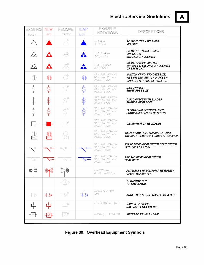
Electric Service Guidelines
Page 85
Figure 39: Overhead Equipment Symbols
A

Electric Service Guidelines
Page 86
Figure 40: Lighting Symbols
A
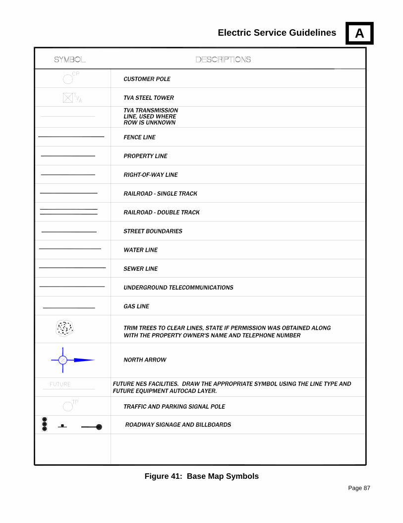
Electric Service Guidelines
Page 87
Figure 41: Base Map Symbols
A

Electric Service Guidelines
Page 88
APPENDIX C: SAFETY CLEARANCES
Drawing Notes: 1. These clearances meet or exceed the National Electrical Safety Code (NESC) 2007 edition, Table
232-1. 2. NESC Exception #1: Where the height of attachment to a building does not permit service drops
to meet these values, clearances may be reduced to ten feet (10’) for a service drop over a residential driveway. (The height of the drip loop shall have a minimum of ten feet (10’). ) NESC Exception #2: Maintain a minimum of twenty-four feet (24’) from the lowest NES attachment over all state roads, especially interstates. NESC Exception #3: Railroad clearances shown are specified by CSX Form 767 (Rev. 8-88). These clearances are for a line seventy-five feet (75’) or less from the pole to the farthest rail. If the distance exceeds seventy-five feet (75’), the clearance shall be increased by one-twentieth foot (0.2’) for each ten feet (10’) in excess of seventy-five feet (75’). Additionally, rails shall have at least twelve feet (12’) clearance from the nearest obstruction such as poles or anchors.
3. Secondary distances are for triplex or quadruplex. Add six inches (6”) for open-wire secondary.
Railroadtracks
(farthest rail75 ft or less)
Roads, streets,alleys,
parking lots,subject
to truck traffic
Residentialdriveways,commercial
areas not subjectto truck traffic
Other landtraversed by
vehicles (forest,orchards,
grazing, etc.)
Spaces orways subjectto pedestriantraffic only
20'-0"
22'-0"
30'-0"
32'-0"
18'-0"
20'-0"
27'-0"
27'-0"
22'-0"
18'-0"
69 kV
2.4kV TO 23.9kV
Comm.
Secondary
Dist Voltage
Neutral Guy
12'-0"
15'-0"20'-0"
22'-0"
16'-0"
15'-6"
16'-0"
15'-6"
17'-0"
9'-6"
Messenger
69 kV
Figure 42: Vertical Clearances
A

Electric Service Guidelines
Page 89
Drawing Notes: 1. These clearances meet or exceed the NESC 2007 edition, table 234-1. Sixty-nine (69) kV
horizontal clearance includes a three feet (3’) blow-out allowance (clearance may require additional distance based on framing or span length).
2. Pedestrian access applies if roof can be reached by ramp, stairway, doorway or permanent ladder. 3. Vehicle clearances apply if vehicles eight feet (8’) or greater in height are allowed. 4. Secondary distances are for triplex or quadruplex. Add six inches (6”) for open-wire secondary
unless otherwise noted.
Figure 43: Building Clearances
A
Secondary
All Primary2.4 kV TO 23.9 kV
Secondary
69 kV
69 kV
2.4 kV TO 23.9 kVAll Primary
69 kV
All Primary2.4 kV TO 23.9 kV
Secondary
(10'6" for open-wire)
Roof not accessible to pedestrians
Roof accessible to vehicles
Com
mer
cial Communications,
Messengers, Neutrals
Balcony or roof
accessible to
pedestrians
15'-1"
11'-0"
13'-6"R
esid
entia
l
20'-1"
18'-6"
15'-6"
16'
Secondary5'
All Primary2.4 kV TO 23.9 kV
69 kVCommunications,
Messengers, Neutrals
10'-0"
7'-6"
Communications, Messengers, Neutrals
4'-6"
5'
Communications, Messengers, Neutrals
Note: In the 2007 NESC, the horizontal distances are the same for walls, projections, windows, and balconies accessible to pedestrians.
4'6"
12'1"
7'6"
10'6" for open-wire
Roof not accessible to pedestrians
3'-0"
3'6"
14'-1"
12'-6"
12'-6"
14'-1"
3'6"
3'-0"
12'-1"

Electric Service Guidelines
Page 90
Drawing Note: 1. These clearances meet or exceed the NESC 2007 edition, table 232-1 and 234-1. 2. For boat ramps and associated rigging area, add five feet (5’) to the applicable “Sail Boating
Allowed” clearance.
3. Secondary distances are for insulated triplex or quadruplex. Add six inches (6”) for open-wire secondary.
Figure 44: Swimming Pool and Waterways Clearances
A
Fence
5'
NESC/State defined pool enclosure
NESC 351C1 - Underground
25' to pool
NESC 234E1
Dist. Voltage
Secondary
SWIMMING POOL CLEARANCES
Metro public pools require
WATER AREA CLEARANCES
SAILBOATING ALLOWEDNO SAILBOATING
69kV
DIST VOLT.
SEC. VOLT
NEUTRAL, GUY OR MESSENGER
<20 acresUnobstructed 20-200 acres 200-2000 acressurface area of:
>2000 acres
18' 6"
14' 6"
14' 0"
17' 0"
22' 0"
20' 6"
18' 0"
17' 6"
30' 0"
28' 6"
26' 0"
25' 6"
36' 0"
34' 6"
32' 0"
31' 6"
42' 6"
40' 6"
38' 0"
37' 6"
BOAT RAMPS & ASSOC. RIGGING: Add 5' to the applicable Sailboating Allowed clearance.
Exception:
22.5' to pool
22' to pool Neutral, guy or messenger
(fence is considered an enclosure)20' from the pool enclosure
as the edge of the swimming pool.
20'lines are at least five feetfrom the pool wall.
17' to diving platform or tower
14.5' to diving platform or tower
14' to diving platform or tower
19'1" to diving platform or tower27'1" to pool 69 kV

Electric Service Guidelines
Page 91
Drawing Notes: 1. These clearances meet or exceed the NESC 2007 edition. Applicable rules are listed on the
drawing. 2. These distances are minimums. NESC Rule 235H requires clearances between lines of different
communication companies to be at least four inches (4”) anywhere in the span. NESC Rule 235H also requires spacing between messengers supporting communications cables to be at least twelve inches (12”). This may necessitate spacing at the pole greater than the NESC minimum pole spacing shown.
These measurements are from lowest rack if no CATV conduit
20" minbottom of drip loop to 120 V signal line
40" min from bottom of drip loop to NES control cable or top communication cable if 120 V signal line not present
40" minfrom 120 V signal line to NES control cable or top communication cable if 120 V signal line present
30" min distance
4" min distance
4" min distance
* NOTE: Mid-span spacing between different communications must be at least four inches. If more than 12 inches is needed at the pole to obtain four inches at all points, the four inch spacing is the overriding factor.
Maintain 30" min. seperation between neutral or any voltage lines.
neut
ral
com
mun
icat
ion
lines
12" min*
12" min*12" min*
Telephone space24 ft
12" min*
Street light to 120 V signal line:12 inches gounded street light20 inches ungrounded street light
24"
12"
Communication lines and minimal voltage Public Works Signals, in no particular order
(NESC Tables 235-5 and 238-1)40 inches = Worker Safety Zone
N.E.S. Control Cable
Telephone
(NESC Rule 235H)
CATV power supply conduit/weatherhead
120 Volt Signal Line (Public Works)
(NESC Table 238-2 third row)
3W Secondary Rack (NES Neutral)
N.E.S. Messenger
Figure 45: Communications Clearances
A

Electric Service Guidelines
Page 92
Drawing Notes: 1. These clearances meet or exceed the NESC 2007 edition, Table 234-1. 2. All clearance measurements are taken from the closest point of the line to the closest point of the
object. 3. Secondary distances are for triplex or quadruplex. Add six inches (6”) for open-wire secondary
unless otherwise noted.
Figure 46: Street Light Fixture & Fire Hydrant Clearances
A
Supporting Structure
VerticalNESC 234B2
Supporting Structure
VERTICAL
69 kV lines (transmission)
All primary 2.4 - 23.9 kV
Secondary
Neutral, MessengerGuys, Communications
HORIZONTAL
4'-6"Secondary
3'-6"
Fire Hydrant(per Metro
HorizontalNESC 234B1
Neutral, Messenger, Guys, Communications
Fire Marshall)
5' sidewalk4' grass strip
10'-0"
(may vary dependingon sag and blowout)
3'-6"
69 kV lines (transmission)
9'-1"
All primary 2.4 - 23.9 kV7'-6"
6' 1"
2'
4'-6"

Electric Service Guidelines
Page 93
Drawing Notes: 1. These figures are taken from the September 1998 update of the Americans with Disabilities Act
Accessibility Guidelines (ADAAG) for Buildings and Facilities. ADAAG serves as the basis for standards used to enforce the design requirements of the ADA. These standards are maintained by the U.S. Department of Justice (DOJ) and the U.S. Department of Transportation (DOT). It is these standards that the public is required to follow.
2. On the left figure, the twenty-four inches (24”) represents the length of the item that must be maneuvered around by the wheelchair, which in this case would be the utility pole. Unless the pole diameter is such that there will be less than thirty-two inches (32”) of sidewalk clearance for a twenty inch (24”) distance, this is the absolute minimum clearance required. However, sixty inches (60”) clearance should be allowed whenever possible, as shown in the figure on the right.
Figure 47: ADA Sidewalk Clearances
A
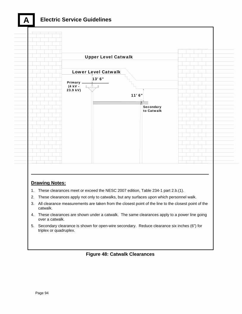
Electric Service Guidelines
Page 94
Drawing Notes: 1. These clearances meet or exceed the NESC 2007 edition, Table 234-1 part 2.b.(1). 2. These clearances apply not only to catwalks, but any surfaces upon which personnel walk. 3. All clearance measurements are taken from the closest point of the line to the closest point of the
catwalk. 4. These clearances are shown under a catwalk. The same clearances apply to a power line going
over a catwalk. 5. Secondary clearance is shown for open-wire secondary. Reduce clearance six inches (6”) for
triplex or quadruplex.
11' 6"
Secondary to Catwalk
Upper Level Catwalk
Lower Level Catwalk
Primary(4 kV -
23.9 kV)
13' 6"
Figure 48: Catwalk Clearances
A
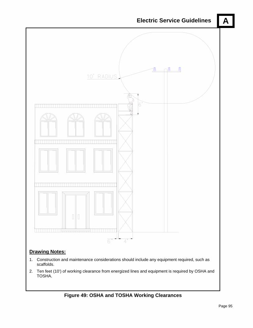
Electric Service Guidelines
Page 95
A
Drawing Notes: 1. Construction and maintenance considerations should include any equipment required, such as
scaffolds. 2. Ten feet (10’) of working clearance from energized lines and equipment is required by OSHA and
TOSHA.
Figure 49: OSHA and TOSHA Working Clearances

Electric Service Guidelines
Page 96
Drawing Notes: 1. These guidelines apply to all pad-mounted equipment, including single and three phase transformers,
residential and commercial. 2. Transformers SHALL NOT be installed, under any circumstances, less than three feet (3’) from a building
or any other structure. Transformers installed less than the distance indicated as “A” shall have a fire barrier wall installed between the transformer and the building.
3. The barrier shall be constructed of non-combustible material so it will qualify as a 4-hour fire wall (solid concrete block, reinforced concrete, steel, or eight inch (8”) brick).
4. Transformers may be installed closer to the building than shown above as distance “A” if the following conditions are fully satisfied:
• The exposed wall construction is fire-resisting in nature, such as eight inch (8”) brick.
• The exposed wall shall be rated as a 4-hour fire wall.
• There is no exposure to combustible eaves or trim.
• Any opening in the exposed wall at the same level as the transformer within the separation distance required (above) shall be protected with approved fire doors.
• Any openings in the wall above the transformer for the second and third stories above the transformer level shall be protected with fixed wired glass in a steel frame.
5. Refer to NFPA 70 article 450-27; and NESC Section 15 - 152.A.2 for complete rules.
BA
RR
IER
BUILDING(Top View)
3 ftmin
Concrete Pad & Transformer
* No wall neededif this distanceis greater than or equal to "A"
2 ft
2 ft
Concrete Pad & Transformer
BUILDING(Side View)
1 ft
3 ftmin
*
BA
RR
IER
Transformer Size “A” distance
Minimum wall dimensions
0 thru 75 kVA (most residential
services will be in this category)
10 feet 8 ft wide x
7 ft tall
76 thru 333 kVA 20 feet
over 333 kVA 30 feet
10 ft wide x 8 ft tall
Figure 50: Fire Barrier Wall
A

Electric Service Guidelines
Page 97
A
Drawing Notes: 1. Fiberglass terminating cabinet pad (NES Stock #060010000) furnished by NES and installed by the
Customer. 2. Customer to backfill within six inches (6”) of the top of the conduit with #67 crushed gravel. 3. Grounding to be furnished and installed by Customer. 4. A minimum of six feet (6’) clearance is required at the front of fiberglass terminating cabinet pad-box. A
minimum of three feet (3’) is required from the pad-box on the other three sides. This includes signs, structures and the outermost branches of mature plants used for landscaping.
Figure 51: Pad for Single-phase Primary Terminating Cabinet
APPENDIX D: ADDITIONAL INFORMATION
SCH 40 PVCLENGTH AS NEEDED
TOP VIEW
CABLE OPENING
18"
32"
12"
SEAL THE CONDUIT END(S) AND SECURETHE PULL TAPE
PVC END TOPROTECT CABLE
SELECTED BACKFILLTO FINISHED GRADE
1" MIN TO 5" MAX ABOVE FINISHED GRADE
12" # 67 CRUSHED GRAVEL
COPPER GROUND WIREFURNISHED AND INSTALLED BY
CUSTOMER.LEAVE A 10' COIL AT EACH END
FOR CONNECTIONS
# 67 CRUSHED GRAVELUNDER AND INSIDEPAD-BOX
FIBERGLASS PAD-BOXFURNISHED BY NESINSTALLED BY OTHERS
RIGID GALVANIZED ELBOWAND ADJACENT 10' SECTION
ELBOW RADIUS = 24"DIAMETER AS SPECIFIED
IN THE NES CONSTRUCTIONDRAWING(S)
WARNING TAPENES FURNISHED AND
INSTALLED
30" min
42"
NOTE:ALL MATERIALS, LABOR AND EQUIPMENT NECESSARY TO COMPLETEEXCAVATION, CONDUIT INSTALLATION, AND BACKFILLING SHALL BEFURNISHED BY THE CUSTOMER OR THE CUSTOMER'SREPRESENTATIVES HEREIN REFERRED TO AS OTHERS ORCUSTOMER.
END VIEW
23"
1'
6"
TERMINATING CABINET:NES FURNISHED AND INSTALLED.
DETAILS FOR THE PAD-BOX ANDCABINET WILL BE FURNISHED
AT THE PRE CONSTRUCTION MEETING.
37"
2'-8"

Electric Service Guidelines
Page 98
A
Drawing Notes: 1. Fiberglass terminating cabinet pad box (NES Stock #060015000) to be furnished by NES and installed by the
Customer. 2. Customer to backfill within six inches (6”) of the top of the conduit with #67 crushed gravel. 3. Multiple conduits to be grouped at the single conduit location when applicable. 4. A minimum of six feet (6’) distance is required at the front of terminating cabinet door. A minimum of three
feet (3’) is required from the pad on the other three sides. This includes signs, structures and the outermost branches of mature plants used for landscaping.
Figure 52: Pad for Three-phase Primary Terminating Cabinet
23"
END VIEW
5'-6"
NOTE:ALL MATERIALS, LABOR AND EQUIPMENT NECESSARY TO COMPLETEEXCAVATION, CONDUIT INSTALLATION, AND BACKFILLING SHALL BEFURNISHED BY THE CUSTOMER OR THE CUSTOMER'SREPRESENTATIVES HEREIN REFERRED TO AS OTHERS ORCUSTOMER.
42"30" min
WARNING TAPENES FURNISHED AND
INSTALLED
RIGID GALVANIZED ELBOWAND ADJACENT 10' SECTION
ELBOW RADIUS = 24"DIAMETER AS SPECIFIED
IN THE NES CONSTRUCTIONDRAWING(S)
1' FIBERGLASS PAD-BOXFURNISHED BY NESINSTALLED BY OTHERS
# 67 CRUSHED GRAVELUNDER AND INSIDEPAD-BOX
COPPER GROUND WIREFURNISHED AND INSTALLED BY
CUSTOMER.LEAVE A 10' COIL AT EACH END
FOR CONNECTIONS
TERMINATING CABINET:NES FURNISHED AND INSTALLED.DETAILS FOR THE PAD-BOX ANDCABINET WILL BE FURNISHEDAT THE PRE CONSTRUCTION MEETING.
1" MIN TO 5" MAX ABOVE FINISHED GRADESELECTED BACKFILLTO FINISHED GRADE
PVC END TOPROTECT CABLE
SEAL THE CONDUIT END(S) AND SECURETHE PULL TAPE
6"
12"
58.5"
18"CABLE OPENING
TOP VIEW
SCH 40 PVCLENGTH AS NEEDED
CONCRETEENCASEMENT
2'-8"

Electric Service Guidelines
Page 99
A
Drawing Notes: 1. Maximum number of permanent service conduits is five (5), including the feeder conduit from riser
pole to pull box. Conduits are three inch (3”) diameter, unless specified otherwise on the design drawing. Additionally, there can be a three inch (3”) temporary conduit, and a two inch (2”) street lighting conduit installed in the pull box.
2. Fiberglass pull box (NES Stock #060034000) is furnished by NES and installed by the Customer. 3. Customer to backfill as shown with #67 crushed gravel. 4. Final grade shall be within one inch (1”) of the top of the fiberglass pull box. 5. A minimum of three feet (3’) clearance is required all around the pull box cover. This includes signs,
structures and the outermost branches of mature plants used for landscaping.
Figure 53: Secondary Pull Box
3'-3"
1'-5"
2'-9"
Side View
End View
2'-2"
SEAL THE CONDUITEND(S) AND SECURE
THE PULL TAPEFLUSH WITH FINISH GRADE
SCH 40 PVCSECONDARY CONDUIT(S)
3" DIAMETER
SELECTED BACKFILLTO FINISHED GRADE TO CUSTOMER(S)
METERTO RISER POLE ORPAD MOUNTEDTRANSFORMER
Top View
SCH 40 PVC ELBOW3" DIAMETER
24" RADIUS
NASHVILLE ELECTRIC SERVICE
SELECTED BACKFILLTO FINISHED GRADE
DITCH INSTALLATION PROCESS1. EXCAVATE DITCH2. INSTALL CONDUIT3. CALL FOR INSPECTION4. BACKFILL 12" AS REQUIRED5. CALL FOR INSPECTION6. AFTER WARNING TAPE IS INSTALLED, BACKFILL TO FINISHED GRADE
12" # 67 CRUSHED GRAVEL
30" min
12"
42"6"
1'
FIBERGLASS PULL-BOXFURNISHED BY NESINSTALLED BY OTHERS
# 67 CRUSHED GRAVELUNDER PULL BOX
SCH 40 PVCSECONDARY CONDUIT(S)3" DIAMETER
NOTE:ALL MATERIALS, LABOR AND EQUIPMENT NECESSARY TO COMPLETEEXCAVATION, CONDUIT INSTALLATION, AND BACKFILLING SHALL BEFURNISHED BY THE CUSTOMER OR THE CUSTOMER'SREPRESENTATIVE(S) HEREIN REFERRED TO AS OTHERS ORCUSTOMER.
WARNING TAPENES FURNISHED AND
INSTALLED
SCH 40 PVC ELBOW(S)3" DIAMETER24" RADIUS

Electric Service Guidelines
Page 100
A
Drawing Notes: 1. Concrete Pull box furnished by NES (NES Stock #060044000) and installed by the Customer. 2. Customer to backfill inside box within six inches (6”) of the top of the conduit with #67 crushed gravel. 3. Final grade shall be within one inch (1”) of the top of the pull box. 4. A minimum of three feet (3’) clearance is required all around the pull box cover. This includes signs,
structures and the outermost branches of mature plants used for landscaping.
Figure 54: Primary Pull Boxes
RIGID GALVANIZED ELBOWAND ADJACENT 10' SECTIONELBOW RADIUS = 24"DIAMETER AS SPECIFIEDIN THE NES CONSTRUCTIONDRAWING(S)
4'-3"
2'-6"
2'-9"
1' 1'
1'-6"
4'-3" Side ViewEnd ViewTop View
Inside ViewNOTE:ALL MATERIALS, LABOR AND EQUIPMENT NECESSARY TO COMPLETEEXCAVATION, CONDUIT INSTALLATION, AND BACKFILLING SHALL BEFURNISHED BY THE CUSTOMER OR THE CUSTOMER'SREPRESENTATIVES HEREIN REFERRED TO AS OTHERS ORCUSTOMER.
SEAL THE CONDUIT END(S)AND SECURE THE PULL TAPE
2'FLUSH WITH FINISH GRADE
RIGID GALVANIZED ELBOWAND ADJACENT 10' SECTIONELBOW RADIUS = 24"DIAMETER AS SPECIFIEDIN THE NES CONSTRUCTIONDRAWING(S)
ELECTRIC ELECTRIC
SELECTED BACKFILLTO FINISHED GRADE SELECTED BACKFILL
TO FINISHED GRADE
12" SELECTED BACKFILL ORAT NES'S DISCRETION# 67 CRUSHED GRAVEL
36" min
12"
42"
6"1'
PRECAST PULL-BOXFURNISHED BY NESINSTALLED BY OTHERS
# 67 CRUSHED GRAVELUNDER PULL BOX ORCONCRETE AT NES'SDISCRETION
WARNING TAPENES FURNISHED AND
INSTALLED

Electric Service Guidelines
Page 101
Drawing Notes: 1. A spare conduit is strongly recommended, and may be required at the Engineer’s discretion, to facilitate
future repairs and maintenance. 2. Actual number and sizes of NES conduits and conduit fittings shall be shown on construction drawings, which
shall be presented at the Pre-Construction Meeting. 3. There shall be a minimum of twelve inches (12”) horizontal and vertical clearance between NES conduits and
any other conduits. 4. The Customer is responsible for soil stabilization during and after construction.
A
Figure 55: Trench Requirements for Solid Rock Conditions
DITCH INSTALLATION PROCESS1. EXCAVATE DITCH2. INSTALL CONDUIT3. CALL FOR INSPECTION4. POUR CONCRETE,5. CALL FOR INSPECTION6. AFTER WARNING TAPE IS INSTALLED, BACKFILL TO FINISHED GRADE
3" MINIMUM SURROUNDINGCONCRETE ENCASEMENTBETWEEN GALVANIZED ELBOWSUNLESS SPECIFIED OTHERWISEBY NES DITCH INSPECTOR
Customer Ditch Detail for Solid RockConditions
Warning Tape:NES Furnishedand Installed
NES NES
SELECTED BACKFILLTO FINAL GRADE
24" min
16"SOLID ROCK
A separate ditch isrequired for parallelutilities
MIN 12"
Provided and installed by the Customer
NES conduit(s) (plus spare conduit if required)
OTHER UTILITY

Electric Service Guidelines
Page 102
A
Drawing Notes: 1. This provision is only required for commercial subdivisions. It is installed to provide conduit for
future energy services. 2. Conduit sizes and radius of elbows will be specified during the Pre-Construction Meeting.
Figure 56: Primary Pull Box with Energy Services Provisions
SOURCE
LOAD
Customer to installduct to lots as
required.
Center line location for twoducts, as specified for job, tobe installed by Customer
Customer to installduct as required.
MIN 3'
Energy Services Duct(s)
MIN 3'
Customer to installduct as required.
Customer toinstall duct to
lots as required
DETAIL "A": Fed from pad mounted switch
DETAIL "B": Fed from manhole
Conduits should break out ofduct run so they do not gounderneath the pad.
1-1/2" duct betweenswitch and pullbox
1-1/2" ductbetween manhole
and pullbox
Conduits should break out ofduct run so they do not gounderneath the pad.
NES ownedpadmounted switch
Source side towards road
ENERGYSERVICESPULLBOX
NES manhole
ENERGYSERVICESPULLBOX
Energy Services Duct(s)

Electric Service Guidelines
Page 103
Drawing Notes: 1. NES will provide these markers (NES Stock #465337000) for the contractor/Customer to install. 2. If markers have been removed, the conduit should be located by digging in the general location. If locating
the conduit by digging is unsuccessful, call NES Customer Engineering (747-3641) to locate conduits.
! Do not remove or cut off these markers. They are placed when conduit is installed to provide the Customer with a quick and easy means for locat-ing the stub-out. Removal can delay construction.
Figure 57: Conduit Stub-out Marker
A
B
FOR INFORMATIONCALL 747-3642
DO NOTREMOVE
OUT
BELOWLOT #
S
UT
CONDUIT

Electric Service Guidelines
Page 104
Drawing Notes: 1. Exact placement of the bollard(s) will be determined by the NES Engineer. Bollards shall be a
minimum of six feet (6’-0”) from the front of the transformer pad, and three feet (3’-0”) from the other sides.
2. Preferred color is safety yellow. Post shall have a yellow or brightly colored paint to make it visi-ble.
Figure 58: Bollard/Guard Post
3000 PSI 1'-0" min.concrete
4" galvanized pipe filled with 3000 psi concrete.
3'-0"
2'-0" min.3'-0" preferred
4'-0" min.5'-0" preferred
5'-0"
6" galvanized pipe filled with 3000 psi concrete.
concrete
1'-0" min.
3000 PSI
STANDARD BOLLARD INSTALLATION INDUSTRIAL AREA BOLLARD INSTALLATION
A

Electric Service Guidelines
Page 105
Drawing Notes: 1. NES will place these decals on the door of pad-mounted transformers, terminating cabinets and
switches after they are set on the pad. 2. Clearances around pad-mounted equipment are six feet (6’) in front and three feet (3’) from the
sides and back. 3. NES reserves the right to trim or remove any landscaping, signs or other items placed closer to
the equipment than indicated on this label. This may be necessary to restore or maintain service, and/or to ensure the employee’s safety while operating the equipment. Items removed from the clear zones will not be replaced by NES.
Figure 59: Equipment Warning Label
A

Electric Service Guidelines
Page 106
A
Residential Subdivision Application for Service Date Submitted _____________ Developer/Owner name _________________________________________________________ Property Location ______________________________________________________________ Name of Development/Phase _____________________________________________________ Single Family _______ Multi-Family _______ Responsible Party ______________________________________________________________ (authorization letter required from property owner if different from responsible party) Property Owner ________________________________________________________________ County Tax Map # _____________________________________________________________ Parcel # ______________________________________________________________________ Deed of Record # ______________________________________________________________
Type of Primary Electric Service (Overhead, Underground, or Overhead w/Underground Secondary): ___________________________________________________________ Number of lots/units: ________ Average square footage: ________ Type of heat (gas/electric): ________ kW of heat: ________ If gas heat, any additional electric heat pumps? Yes ____ No ____ Tons ______ Average tons of air conditioning: ________ Number of water heaters: Gas ____ Electric ________ Sidewalk plans (if applicable): ________ (If Yes, provides _____ ft width for grass strip) Street Lighting required per City Public Works or private lighting along private road? (Yes or No)

Electric Service Guidelines
Page 107
The following items must be provided before an estimate can be initiated:
o AutoCAD Civil site drawing in State Plane coordinates (email to [email protected]) o Included with application
Yes ____ No ___ o Building Envelopes shown on Civil site digital drawings o Proposed or Existing easements on Final Plat (Standard 20-ft PUE adjacent to roads) o UG High voltage layout when zoning setbacks restrict 20-ft easements (ie, SP, UDO, UZO and
PUD plans must allow for electrical pad-mounted equipment) o Fire Hydrant Locations o Grading Plans o Storm Water Plans o Water & Sanitary Sewer Plans o 3-phase power requirements o Multi-unit dwelling proposed meter locations (if applicable) o Meter Pedestals required on Multi-unit dwelling (if applicable)
The following items must be provided before an estimate can be finalized:
o Proposed Grading start date ________ o Permanent Energize service date _______ o Sidewalk & grass strip details o Street Lighting plans if mandatory by City Public Works (Metro, Brentwood, etc…) o Stream Crossings and bridge cross-sections o Postal Plans identify address (multi-family only) o 3 Phase Multi-meter Secondary Termination Enclosure required (no troughs allowed) o Dry-type vault room required (if applicable)
Additional comments: __________________________________________________________ ____________________________________________________________________________ ____________________________________________________________________________ Please note Customer and Street Lighting Handbooks are available at www.nespower.com Section below to be completed by NES: _____________________________________________________________________________ Date Received by NES: ________________________ NES job owner: _____________________ Work Request #: _____________________ NES drawing number: ________________
A Residential Subdivision Application continued:

Electric Service Guidelines
Page 108
Update Review Committee Harold Freeman (Meter Department) Jim Purcell (Energy Services Engineering) Frank Spickler (Construction and Maintenance) Ronald Reasonover (Customer Engineering, Standards) Jim Crafton (Customer Engineering) Brad Batts (Customer Engineering) Chris Weathers (Customer Engineering, Standards) (Editor) Approved By: ____________________________ Ron Davidson Engineering Supervisor Customer Engineering, Standards and Network Section Approved By: ____________________________ Nick Thompson Engineering Manager Customer Engineering