design guidelines - site
TRANSCRIPT
Michigan State University DESIGN GUIDELINES
SITE AND UTILITY INFRASTRUCTURE Page 1
PAGE TABLE OF CONTENTS 1 SITE 2
1. Comprehensive Site Design Guidelines 2. Universal Accessibility 3. Sustainability 4. Considerations and Responsibilities 5. Pathways 6. Grading 7. Vehicle Parking 8. Road Design 9. Americans with Disabilities Act Requirements 10. Obstacles and Protruding Project Problems 11. Pedestrian Signals 12. Crosswalk Pavement Markings 13. Maintenance of Sidewalks in the Vicinity of Construction Sites 14. Bus Stops 15. Bicycle Facilities 16. Building Services Areas 17. Materials and Installation
UTILITY INFRASTRUCTURE 20
1. Utility Design 2. Campus Utility Systems
CS_DSG_DESIGN_GUIDELINES - SITE.docx Rev. 11/12/2015
Michigan State University DESIGN GUIDELINES
SITE AND UTILITY INFRASTRUCTURE Page 2
1. COMPREHENSIVE SITE DESIGN GUIDELINES
A. M.S.U. strives for long term quality construction. Not only is an attractive appearance of
the campus a primary reason why parents and students select M. S.U. but repeated repairs is not cost effective and, significantly disrupts the effective functioning of this World Class institution 24/7/365 days a year.
B. Consultants are expected to be thoroughly familiar with and follow the Owner’s design and construction standards. Consultants must be granted prior approval for any deviations from MSU Standards (details and specifications) before incorporating them into the Project Documents.
C. Designs shall adhere to the principles of “Complete Streets”, Michigan Public Act 135 of
2010 for all campus streets (roads). “Complete Streets” are roadways that are planned, designed and constructed to provide appropriate access to all legal users in a manner that promotes safe and efficient movement of people of all ages and abilities whether by car, truck, public transportation, transit assistive device, foot or bicycle. The design standards that follow provide guidance to meet and exceed the requirements of the Act. Emphasis shall be placed in order of importance beginning with pedestrians followed by bicyclist then public transportation then personal vehicles and lastly with trucks. The Detailed Site Design Standards incorporate the design provisions for designing Complete Streets. If any section of the MSU Design Standards are more extensive than Complete Streets, than the MSU Standards shall prevail.
2. UNIVERSAL ACCESSIBILITY
A. Americans with Disabilities Act (ADA), Public Law 101-336 must be followed as the
standard in the design of accessible features in new construction and alterations.
B. Design shall comply with the State of Michigan Barrier-Free Design requirements. When there is a conflict, ADA must govern. When a Michigan requirement exists, and ADA does not, the Michigan code must apply.
C. Generally, all building entrances, (including loading docks for dollys used by vans and
delivery vehicles with-out lift gates shall have ADA regulated ramps) shall be grade level from the path ramp at the adjacent street or barrier free parking. Additional accessible routes may also be required depending on current or future use of the building and/or site.
3. SUSTAINABILITY
A. Design consideration should include concepts that are appropriate for the project in accordance with The Sustainable Sites Initiative (SITES), as directed by the Owner. It is not the intent of these references to include as many of the scorecard items or benchmarks if they are not truly appropriate for the project goals.
B. Reference the Low Impact Developemt Manual for Michigan published by SEMCOG, Southeast Michigan Council of Governments.
C. Flood Control:
CS_DSG_DESIGN_GUIDELINES - SITE.docx Rev. 11/12/2015
Michigan State University DESIGN GUIDELINES
SITE AND UTILITY INFRASTRUCTURE Page 3
• The first floor elevation of any building shall be a minimum of 12” higher than
the highest part of any of the adjacent surrounding roads. • After the building site has been determined and floor elevations are established,
check flood levels and heavy rainfall conditions for any possible problems. Design changes shall be made to eliminate these problems and make the building flood-proof.
• Flood maps of the campus are on file at Infrastructure Planning and Facilities, Planning, Design and Construction.
• Reference to the historical flood elevations at the Farm Lane Bridge ◊ 1904 – 838.80 ◊ 1947 – 835.81 ◊ 1960 – 833.59 ◊ 1975 – 836.34
D. Storm Water Management: Reference MSU’s stormwater design guidelines.
E. Soil Movement on the Owners Property
• General: In order to limit liability and improve upon the long term planning
process the Owner has determined that it is appropriate to track the movement of large quantities of soil onto or around the Owners property. The following policy outlines the procedures for tracking these soils that shall be documented with project records
• Record Keeping: Planning, Design and Construction (PDC) shall develop and maintain a campus map on the GIS website that includes the following attributes:
◊ Areas of Known soil contamination ◊ Suspect areas requiring further investigation should further development
occur ◊ Locations of relocated soils in quantities greater than 500 CY ◊ Soil description and compaction criteria for filled areas if known ◊ Locations of non-contaminated fill that create a future liability for
development. Ex: concrete and rubble fill • Minimum Soil Quantity Requirements: If the project requires the movement of
more than 500CY of soil on campus, prior approval from the Vice President for Infrastructure Planning and Facilities. The request shall include appropriate information regarding location, quantities and reason for the soil movement.
• Contaminated Soil Reporting Procedure: If contaminated soils are discovered during construction, the Project Representative will contact the Office of Environmental Health and Safety (EHS) immediately. EHS will inform the VPIPF and direct any required remediation, including maintaining appropriate records indicating quantities, type of contaminants and location for disposal.
• Documentation: IPF staff shall document the location of all contaminated soils and maintain a correspondence records related to the movement of soils regulated by this policy.
• Exempt Activities: ◊ Temporary processing of topsoil for reuse on Owners property ◊ Removal of clean spoils from project site in which the spoils are lawfully
disposed of off Owners property
CS_DSG_DESIGN_GUIDELINES - SITE.docx Rev. 11/12/2015
Michigan State University DESIGN GUIDELINES
SITE AND UTILITY INFRASTRUCTURE Page 4
◊ Placement of clean existing fill soil or engineered fill soil or topsoil on
Owners property.
4. CONSIDERATIONS AND RESPONSIBILITIES
A. All site planning must conform to the current MSU Campus Master Plan which contains the Campus Planning Principles, System Frameworks, University Zoning Ordinance and various documents and images that are essential for integrating new campus designs into the current fabric of the campus. This information is available at cpa.msu.edu.
B. Planning, Design and Construction (PDC) will provide:
• Benchmarks, floor plans, and other existing information, as required to proceed with planning work
• A project specific topographic survey • An existing vegetation inventory map (including commemorative and historically
significant plants) • The locations of all historical markers and monuments. All of which shall be
preserved • Soil reports: boring locations will be determined in coordination with the
Consultant for buildings, structures and appropriate site features.
C. Consultant Responsibilities: Throughout the design process, the site Consultant shall maintain close communication and coordination with the assigned PDC project staff. Coordination by Consultant: The Design Team includes the assigned PDC project staff, other PDC staff, non-IPF MSU employees and other experts that may be hired by MSU. • Site Analysis and On-Site Observation: At concept stage, this shall serve to
identify site conditions and observe existing site use, therefore identifying site development opportunities and limitations early in the process. Thorough photographic documentation is required.
• The campus is a dynamic living/learning environment with a prized woody plant collection woven into the fabric of the campus arboretum. Knowledge and respect of the existing plants is essential to provide a successful project. The Director of the Campus Woody Plant Collection and Campus Arborist are available to assist, should you have questions or concerns. It is the responsibility of the Consultant to get prior approval, should the design negatively impact the campus woody plant collection.
• Design solutions shall integrate sustainable design and best management practices regarding storm water management. Become familiar with the Storm Water Design Standards, which is available on the PDC web site.
• Roadway, crosswalk, bike lane, bus stop and speed table design standard guidelines require coordination with PDC staff and the University Traffic Engineer. See the Appendix for standard MSU details.
• Universal Accessibility shall be provided. See Appendix for Barrier-free Roadway Crossing Guidelines.
• Coordinate heated pavement jointing patterns with planned zones, sensors and manifold locations during the design process. Include PDC Mechanical Engineer and Landscape Architect in the planning.
CS_DSG_DESIGN_GUIDELINES - SITE.docx Rev. 11/12/2015

Michigan State University DESIGN GUIDELINES
SITE AND UTILITY INFRASTRUCTURE Page 5
• Coordinate building service area designs with the Office of Recycling and the
Office of Waste Management (rubbish/recycling truck access, bin orientation, location, quantity, size, an type) and Physical Plant Shops (service vehicle parking).
• Coordinate development of the Landscape Plan Concept with PDC Landscape Architect. Required at end of Design Development for “Step 2 – Authorization to Proceed” presentation.
• Coordinate utility design with appropriate PDC Staff including a Landscape Architect. The Consultant is expected to facilitate the coordination of such items as aesthetics, tree preservation, noise, maintenance, equipment, drains, storm sewer pipe, manholes, overflow drains and turf irrigation systems. Site lighting, emergency phone (Code Blue) and irrigation circuit plans may be required. Circuit plans shall not be diagrammatic but rather illustrate exact wire routes. Routing shall accommodate subsequent landscape plans. Coordinate with PDC Electrical Engineer and Landscape Architect and consulting Electrical Engineer.
• Coordinate a construction site access, construction staging, construction barriers, tree protection and any re-routed pedestrian paths (must accommodate snow removal equipment if the project will last through the winter) during construction. Must be included in construction documents (Landscape Services, MSU Police Department, CATA, PDC Civil Engineer may all be involved with these safety and transportation issues).
• Be familiar with and utilize web-based technical standards, specifications and standard details.
◊ The PDC site detail library, as well and “Design Guideline” drawings, are provided electronically for Consultant use. If unique details are required, contact the assigned PDC project staff. PDC has unpublished details that, with prior approval, may be used and /or slightly modified for the project requirements. See the Appendix for standard MSU details.
D. Owner Responsibilities: Materials and products furnished and/or installed by Owner are listed in the technical specifications are extensive. Therefore prior approval is required before another product will be approved. Design services by Owner include: • Assessment of existing plant material • Determine items to be salvaged and procedure by Owner or Contractor. (Signs,
site lighting, emergency phones, underground wire, street furnishings, parking meters, etc.)
• Planting plan • Irrigation Plan • Site furniture selection and procurement by Landscape Architect. (Removal of
existing furniture and installation of new by Contractor) • Building, regulatory and way-finding sign text and location
5. PATHWAYS
A. Shall be adjacent to each side of a road where ever physically possible to comply with
Complete Streets.
CS_DSG_DESIGN_GUIDELINES - SITE.docx Rev. 11/12/2015
Michigan State University DESIGN GUIDELINES
SITE AND UTILITY INFRASTRUCTURE Page 6
B. Generally, pathways shall be not less than 8’ wide unless specific site conditions require
a different width. When adjacent to the front of parking spaces, the minimum shall be 9.5’ to accommodate parking meters, vehicle overhang of the curb and snow plowing operations.
C. Walking paths shall be constructed of a minimum of 6 inch thick concrete per the
Standard Detail, unless otherwise specified. Other materials and porous pavements will be seriously considered if it fits within the esthetic framework of the site.
D. Concrete pavement immediately adjacent to roadway curb must contain the brick detector
border per the Standard Detail. Pavement adjacent to parking spaces does not require a brick detector border.
E. ADA barrier-free ramps with tactile warning plates shall be at all pathways that cross
vehicle routes including where paths terminate in or cross parking lots. They shall be aligned with the crosswalk where ever possible incorporating the brick band visual aid indicator where ever needed. Warning plates shall not be more than 30” away from the back of curb.
F. Perpendicular intersection walkway radii shall be at least equal to the walk width. Acute
angle radii shall be no more than 1 foot.
G. Pavement at building entrances shall be frost free and separated from the approaching pathway with an expansion joint and supported by a haunch attached to the building wall or a spread footing adjacent to the building. They shall be cured using the wet cure method out to 50’ and then waterproofed after a minimum 30 days drying time after which the standard specified waterproofing product will be applied in accordance with the manufacturers recommendations.
H. All construction joints shall be constructed with epoxy coated dowels per the Standard
Detail.
I. All expansion joints shall have Greenstreak brand, Speed Dowels per the Standard Detail.
J. Pavement adjoining a building or foundation shall be constructed with an expansion joint and haunch, speed dowel or frost free footing.
6. GRADING
A. Detailed grading plan shall show spot elevations at the key forming junctures such as
corners, points of tangency, top and bottom of curb/wall etc.
B. Storm water drainage patterns shall minimize flow across or within pedestrian and bicycle travel ways.
C. Shall conform to Federal ADA rules.
D. Valley gutters shall be constructed of concrete that is 3 feet wide and 12 inches thick
reinforced concrete except where its located between a road/driveway and parking
CS_DSG_DESIGN_GUIDELINES - SITE.docx Rev. 11/12/2015
Michigan State University DESIGN GUIDELINES
SITE AND UTILITY INFRASTRUCTURE Page 7
spaces, in which the thickness can be reduced to 10 inches. Valley gutters that are crossed by vehicles shall remain at 12 inches.
7. VEHICLE PARKING
A. Parking space requirements – standard perpendicular spaces shall be 9’ x 18’ (excluding the gutter pan at the side of the space at ends of the parking bay). Two perpendicular parking bays and one drive lane shall be 60 feet wide.
B. Concrete curb and gutter shall be 24” wide; (integral curbs are rarely approved). Straight
curb is generally prohibited unless site conditions don’t allow for the Standard Detail curb/gutter.
C. Rolled curbs should be poured in locations where snow plows need to push snow review locations with landscape services.
8. ROAD DESIGN
A. Lane Width: All vehicle lanes shall be 10 feet wide with 5 feet wide (single direction)
bike lanes (asphalt pavement surface) (see bike lane design requirements in section 5). Service drives may be wider to accommodate larger vehicles and turning requirements. Bike lanes can be reduced to 4 feet wide if significant woody plant conflicts prohibit the 5 foot lane.
B. Clear Vision Zones: Plans shall identify all clear vision zones throughout the road, paying
particular attention to intersections and curves.
9. AMERICANS WITH DISABILITIES ACT REQUREMENTS
A. Curb Ramps at Vehicle Crossings • Where conditions permit, the slope of the ramp shall be in only one direction,
parallel to the direction of travel through the marked crosswalk. • Curb ramps shall be provided wherever an accessible route crosses a curb/gutter
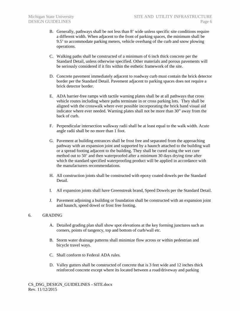
regardless weather it’s marked or not. • Desired design of sidewalk ramps includes the figures below which direct the
pedestrian in the direction of travel/marked crosswalk.
CS_DSG_DESIGN_GUIDELINES - SITE.docx Rev. 11/12/2015
Michigan State University DESIGN GUIDELINES
SITE AND UTILITY INFRASTRUCTURE Page 8
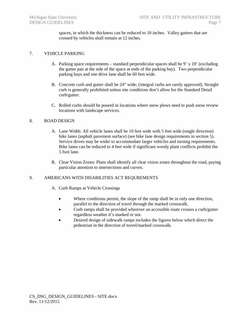
• The ramp slope is a ratio equal to the vertical rise (y) divided by the horizontal run (x). It is equal to the tangent of the angle that the plane of the ramp surface makes with a horizontal (level) plane. Transitions from ramps to walks, gutters, or streets shall be flush and free of abrupt changes. Maximum slopes of adjoining gutters, road surface immediately adjacent to the curb ramp, or accessible route shall not exceed 1:20
• The minimum width of a curb ramp shall be 36 in (915 mm), exclusive of flared sides.
• Ground surfaces along accessible routes and spaces including curb ramps shall be stable, firm, and slip-resistant.
• If a curb ramp is located where pedestrians must walk across the ramp, or where it is not protected by handrails or guardrails, it shall have flared sides; the maximum slope of the flare shall be 1:10.
CS_DSG_DESIGN_GUIDELINES - SITE.docx Rev. 11/12/2015

Michigan State University DESIGN GUIDELINES
SITE AND UTILITY INFRASTRUCTURE Page 9
Note: if X is less than 48 in. then the slope of the flared side shall not exceed 1:12
• This figure shows a typical curb ramp, cut into a sidewalk perpendicular to the curb face, with flared sides having a maximum slope of 1:10. The landing at the top, measured from the top of the ramp to the edge of the walkway or closest obstruction is denoted as "x". If x, the landing depth at the top of a curb ramp, is less than 48 inches, then the slope of the flared side shall not exceed 1:12
• Where the curb ramp is completely contained within a planting strip or other non-walking surface, so that pedestrians would not normally cross the sides, the curb ramp sides can have steep sides including vertical returned curbs.
• Where the curb ramp is completely contained within a planting strip or other non-walking surface, so that pedestrians would not normally cross the sides, the curb ramp sides can have steep sides including vertical returned curbs.
• Defined curb height where the two streets intersect provides two distinctive curb ramps for the two sidewalks. This allows individuals with Visual Impairments to detect a left or right edge to the curb ramp and subsequently avoid diagonal crossing into the intersection
B. Detectable Warning Device: Detectable warnings shall consist of a surface of truncated
domes. • Positioning: A curb ramp shall have a detectable warning. The detectable
warning shall extend the full width of the curb ramp (exclusive of flared sides) CS_DSG_DESIGN_GUIDELINES - SITE.docx Rev. 11/12/2015

Michigan State University DESIGN GUIDELINES
SITE AND UTILITY INFRASTRUCTURE Page 10
and shall extend either the full depth of the curb ramp or 24 inches (610 mm) deep minimum measured from the back of the curb on the ramp surface.
• Dome Size: Truncated domes in a detectable warning surface shall have a base diameter of 0.9 inch (23mm) minimum and 1.4 inches (36 mm) maximum, a top diameter of 50 percent of the base of the diameter minimum to 65 percent of the base diameter maximum, and a height of 0.2 inch (5.1 mm).
• Dome Spacing: Truncated domes in a detectable warning surface shall have a center-to-center spacing of 1.6 inches (41 mm) minimum and 2.4 inches (61 mm) maximum, and a base-to-base spacing of 0.65 inch (17 mm) minimum, measured between the most adjacent domes on a square grid.
• Contrast: Detectable warning surfaces shall contrast visually with adjacent walking surfaces either light-on-dark, or dark-on-light.
• Platform Edges: Detectable warning surfaces at platform boarding edges shall be 24 inches (610 mm) wide and shall extend the full length of the public use areas of the platform.
◊ Material Specifications: Detectable warnings must be made from cast iron. The approved vendor is East Jordan Iron Works, East Jordan, MI 800-874-4100.
C. Sidewalks Parallel to Road Edge: Where sidewalks or paved areas are adjacent to the
roadway and there is not a definable separation of surface character between the pavement edge and curb/gutter of the road, this presents a hazard to pedestrians in areas where lighting is poor or if the pedestrian has a visual impairment. The following solutions are appropriate: • Turf: In areas which are wide enough to adequately maintain turf, place a
continuous strip of turf to separate the sidewalk from the curb/gutter edge of the road.
• Planters: Place a continuous ADA designed planter to separate the sidewalk from the curb/gutter of road
• Differentially Textured Hard Surface: Place a band of contrasting colored bricks for a width of at least 17 inches between the sidewalk and the curb/gutter of road.
10. OBSTACLES AND PROTRUDING OBJECT PROBLEMS:
A. Obstacles and protruding objects in sidewalks present hazards to pedestrians with and
without vision loss, and can create barriers for individuals traveling in wheelchairs or using crutches or other mobility aids, and individuals walking or riding bicycles or walking in small and large groups. Obstacles and protruding objects include, but are not limited to: vegetation, signs, posts, emergency phones, light poles, benches, bollards, rubbish cans, traffic signal poles or similar type obstructions.
B. Signs: Where parking or pedestrian movements occur, the clearance to the bottom of the sign(s) shall be at least 7 feet (2.1 m) above the level of the pavement edge. Signs must not protrude into the pedestrian path of travel. Sign posts are to be located parallel to the pedestrian path of travel with the signage positioned perpendicular to the path of travel.
C. Protruding Objects: Objects between 27 in. and 80 in. (685 mm and 2030 mm) above
ground and not detectable by cane shall not protrude more than 4 in. (100 mm) into sidewalks, corridors, or passageways (including objects mounted on a wall). Objects
CS_DSG_DESIGN_GUIDELINES - SITE.docx Rev. 11/12/2015

Michigan State University DESIGN GUIDELINES
SITE AND UTILITY INFRASTRUCTURE Page 11
mounted with their leading edges at or below 27 in. (685 mm) above the finished floor may protrude any amount. Free-standing objects mounted on posts or pylons may overhang 12 in. (305 mm) maximum from 27 in. to 80 in. (685 mm to 2030 mm) above the ground or finished floor. Protruding objects shall not reduce the clear width of an accessible route or maneuvering space. Protruding objects may be protected by a barrier (including a vertical curb or similar structure) that is detectable.
D. Head Room: Sidewalks, corridors, passageways, or other circulation spaces shall have 80
in. (2030 mm) minimum clear head room. If vertical clearance of an area adjoining an accessible route is reduced to less than 80 in. (nominal dimension), a barrier to warn blind or visually-impaired persons shall be provided.
E. Bollards: When a bollard is placed in the pavement, the following solutions are available
to warn of the hazard:
• Color Contrast: A contrasting color on the bollard is desired (dark green bollard on light colored concrete or white bollard on blacktop as examples of color contrast only and not to be used as specific colors that are approved), to allow for better visual detection of bollards in settings with low lighting and by individuals with visual impairments.
• Flared-bottom Design: The use of bollards with a flared-bottom design is desired as compared to pole design, to allow for the detection of the bollard by individuals in low light and by individuals who are blind and use a long cane.
F. Vegetation: Protruding vegetation which are not maintained can present hazards and sight line concerns for pedestrians, bicyclists, and motorists. • Unobstructed sidewalk or bike path: Vegetation shall be maintained to provide a
clear route on sidewalks and bike paths. All plant material shall be cleared at least one (1’) foot from the pavement edge and eight (8 ft.) above the pavement. In areas of low light, or for individuals with visual impairments, a protruding branch can be a severe hazard to pedestrians and cyclists.
• Sight Line: In areas where vegetation will be added to the landscape, consideration needs to be made with regard to the planting space and areas where pedestrians, cyclists and vehicles may intersect. It is important to consider the mature growth of the vegetation related to the sight line for motorists, cyclists, and pedestrians.
11. PEDESTRIAN SIGNALS
A. An accessible pedestrian signal detector shall be defined as a device designated to assist
the pedestrian who has visual or physical disabilities in activating the pedestrian phase. At accessible pedestrian signal locations, pushbuttons should clearly indicate which crosswalk signal is actuated by each pushbutton. Pushbuttons and tactile arrows should have high visual contrast as described in the “Americans with Disabilities Act Accessibility Guidelines for Buildings and Facilities (ADAAG)”. Tactile arrows should point in the same direction as the associated crosswalk.
B. Acceptable Vendors & Vendor Standards:
CS_DSG_DESIGN_GUIDELINES - SITE.docx Rev. 11/12/2015

Michigan State University DESIGN GUIDELINES
SITE AND UTILITY INFRASTRUCTURE Page 12
• Michigan State University uses the Polara 2 Wire Navigator Accessible
Pedestrian Signal (http://www.polara.com/Nav_Features.htm) which can be ordered through Carrier & Gable, Inc. (http://www.carriergable.com/) – 10/2008.
• Michigan State University adheres to the Michigan Department of Transportation (MDOT) Special Provision for Accessible Pedestrian Signal System: 03T820 (243) - http://mdotwas1.mdot.state.mi.us/public/dessssp/spss/gotoview.cfm, with the following additions/addendums:
◊ 2.A.08 – The Owner uses the MUTCD & MDOT authorized regulatory sign size.
◊ 2.A.08 – The Owner uses contracted Braille for the street name placed on the regulatory sign.
◊ 2.C.07 – The Owner uses the standard color: BLACK ◊ The Owner standard message is: “Street Name” followed by “walk sign”
to indicate the crossing.
C. Location of Push Buttons for Accessible Pedestrian Signals: In locations where pedestrians must actuate the signal for crossing (i.e., mid-block crossings, intersections which are not “time controlled” for classes, etc.) the following standards are required: • Adjacent to a level all-weather surface to provide access from a wheelchair, and
where there is an all-weather surface, wheelchair accessible route to the ramp; • Within 1.5 m (5 ft.) of the crosswalk extended; • Within 3 m (10 ft.) of the edge of the curb, shoulder, or pavement; and • Parallel to the crosswalk to be used.
D. Button Locations: Road without Median: If two accessible pedestrian pushbuttons are
placed less than 10 feet apart or on the same pole, each accessible pedestrian pushbutton shall be provided with the following features: • A pushbutton locator tone, • A tactile arrow, • A speech walk message for the WALKING PERSON (symbolizing WALK)
indication, and • A speech pushbutton information message. • Contracted Braille “Street Name” on the regulatory sign.
E. Button Location – Road with Median: If the pedestrian clearance time is sufficient only
to cross from the curb or shoulder to a median of sufficient width for pedestrians to wait and accessible pedestrian detectors are used, an additional accessible pedestrian detector shall be provided in the median.
F. Pushbutton Locator Tones:
• Pushbutton locator tones shall be easily locatable, shall have a duration of 0.15 seconds or less, and shall repeat at 1-second intervals.
• Pushbuttons should be audibly locatable. Pushbutton locator tones should be intensity responsive to ambient sound, and be audible 1.8 to 3.7 m (6 to 12 ft) from the pushbutton, or to the building line, whichever is less.
CS_DSG_DESIGN_GUIDELINES - SITE.docx Rev. 11/12/2015

Michigan State University DESIGN GUIDELINES
SITE AND UTILITY INFRASTRUCTURE Page 13
• Pushbutton locator tones should be no more than 5 dBA louder than ambient
sound. • The audible tone(s) may be made louder (up to a maximum of 89 dBA) by
holding down the pushbutton for a minimum of 3 seconds. The louder audible tone(s) may also alternate back and forth across the crosswalk, thus providing optimal directional information.
G. Audible Message Standard • When verbal messages are used to communicate the pedestrian interval, they
shall provide a clear message that the walk interval is in effect, as well as to which crossing it applies. The verbal message that is provided at regular intervals throughout the timing of the walk interval shall be:
• MSU Standard: “Street Name” to be crossed followed by “walk sign” to indicate the crossing. (i.e., “Farm Lane, walk sign”).
H. Countdown Pedestrian Signals • Standard Pedestrian Signal Head: A pedestrian interval countdown display may
be added to a pedestrian signal head in order to inform pedestrians of the number of seconds remaining in the pedestrian change interval.
• Accessible Pedestrian Signal Detectors: In areas where the Owner has installed or is using visual countdown pedestrian signals, the audible countdown features within the accessible pedestrian signal pushbuttons will be activated.
• Timing: 3.5 ft/second timing Face-to-Face/curb-to-curb crossing. The assumed flashing “do not walk” is based upon walking speed for pedestrian at 3.5 ft/second from face of curb to face of curb. The minimum walk time should be 20 seconds.
• Pedestrian button activation: Reluctant to rely on the activation of a button by a pedestrian, the button shall always be on recall.
12. CROSSWALK PAVEMENT MARKINGS
A. Evaluate each situation separately with approval from the University Traffic Engineer. Crosswalk pavement markings standards are as follows: • crossing Type Heavy Use Moderate to Light Use
Signalized Intersection Zebra Zebra Road with Stop Sign Zebra Standard Driveway with Stop Sign Standard Standard Mid-Block Crossing Zebra Zebra Parking Lot Entrance Standard Standard Crossing in Parking Lot Zebra Standard Roundabouts Zebra Zebra
13. MAINTENANCE OF SIDEWALKS IN THE VICINITY OF CONSTRUCTION SITES
A. Pedestrian Considerations - A wide range of pedestrians might be affected by temporary
traffic control (TTC) zones, including the young, elderly, and people with disabilities
CS_DSG_DESIGN_GUIDELINES - SITE.docx Rev. 11/12/2015

Michigan State University DESIGN GUIDELINES
SITE AND UTILITY INFRASTRUCTURE Page 14
such as hearing, visual, or mobility. These pedestrians need a clearly delineated and usable travel path which would include:
• Advance notification of sidewalk closures shall be provided and published to the
university community. • Where there are closed sidewalks, a lighted barrier fencing that is detectable by a
person with a visual disability traveling with the aid of a long cane shall be placed across the full width of the closed sidewalk and/or work site.
• Where there are blocked routes, alternate crossings and channelizing routes detectable to pedestrians traveling with the aid of a long cane or who have low vision shall be provided and maintained around the work site.
• Alternate crossings and channelizing routes must include curb ramps and accessibility features for individuals using wheelchairs.
• Sign and signal information should be used to communicate routes around construction to pedestrians.
B. Planning Considerations for Pedestrians in Temporary Traffic Control (TTC) Zones:
• Pedestrians should not be led into conflicts with work site vehicles, equipment, and operations.
• Pedestrians should not be led into conflicts with vehicles moving through or around the work site.
• Pedestrians should be provided with a reasonably safe, convenient, and accessible path that replicates as nearly as practical the most desirable characteristics of the existing sidewalk(s).
• Where pedestrians who have visual disabilities encounter work sites that require them to cross the roadway to find an accessible route, instructions should be provided using an audible information device. Accessible pedestrian signals with accessible pedestrian detectors might be needed to enable pedestrians with visual disabilities to cross wide or heavily traveled roadways.
• A pedestrian route should not be severed and/or moved for non-construction activities such as parking for vehicles, storage of construction equipment or construction materials.
C. When pedestrian movement through or around a work site is necessary, a temporary separate usable sidewalk shall be provided.
• If the previous pedestrian facility was accessible to pedestrians with disabilities, the temporary pathway should also be accessible.
• No abrupt changes in grade or terrain that could cause a tripping hazard or could be a vertical barrier to wheelchair use.
• The sidewalk shall be continuous with curb ramps and all accessibility features.
D. Accessible TTC Zones need to include the following:
• Provisions for continuity of accessible sidewalks should be incorporated into the TTC planning process.
• Access to temporary transit stops shall be provided.
CS_DSG_DESIGN_GUIDELINES - SITE.docx Rev. 11/12/2015
Michigan State University DESIGN GUIDELINES
SITE AND UTILITY INFRASTRUCTURE Page 15
• When channelization is used to delineate a sidewalk, a continuous detectable
edging should be provided throughout the length of the sidewalk such that pedestrians using a long cane can be guided.
• A smooth, continuous hard surface should be provided throughout the entire length of the temporary sidewalk. There should be no curbs or abrupt changes in grade or terrain that could cause tripping or be a barrier to wheelchair use.
• The width of the sidewalk should be a minimum of 1500 mm (60 in.) for the temporary route. Traffic control devices and other construction materials and features should not intrude into the usable width of the sidewalk (permanent or temporary). When it is not possible to maintain a minimum width of 1500 mm (60 in) throughout the entire length of the sidewalk, a 1500 x 1500 mm (60 x 60 in) passing space should be provided at least every 60 m (200 ft), to allow individuals in wheelchairs to pass.
• Signs and other devices mounted lower than 2.1 m (7 ft) above the temporary sidewalk should not project more than 100 mm (4 in) into accessible sidewalks.
14. BUS STOPS
A. Location, size and shape shall be approved by the Owner in consultation with CATA.
B. Bus Stop Location: On two way/two lane roads, locate the bus stop diagonally across from each other with the Bus Stop before the crosswalk. On two lane same direction roads, the bus stop shall be after the crosswalk (refer to standard details). Position at least one street light at the crosswalk (two for multi-lane roads). This layout, provide the maximum sight line for motorist to see departing bus riders who are crossing the road.
15. BICYCLE FACILITIES
A. Bike Paths/Lanes • Road Bike Lanes: Dedicated bike lanes shall be on all streets and roads. Bike
lanes shall be constructed of bituminous pavement. They shall be 5’ wide whenever possible measured from the face of the gutter pan. However, a narrower bike lane to a minimum of 4’ may be approved by the Owner, if existing obstructions (trees, mechanical systems, etc.) dictate the reduction in width.
• Bike Paths: Dedicated bike paths shall be 1) 5’ wide in each direction, 2) adjacent to each other and 3) adjacent to the sidewalk, if one exists nearby and 4) shall be constructed using the Owners standard bituminous material used for parking lots, unless an alternate surface material has been selected by the Owner.
B. Bicycle Parking Areas
• Size and Location: Bike parking areas shall be aesthetically and conveniently located near building entrances. Size of the parking area should accommodate the demand for that entrance, to the extent possible without compromising the buildings appearance.
• Hardware: Specify the standard detail, unless an alternate design has been selected by the Owner.
CS_DSG_DESIGN_GUIDELINES - SITE.docx Rev. 11/12/2015
Michigan State University DESIGN GUIDELINES
SITE AND UTILITY INFRASTRUCTURE Page 16
16. BUILDING SERVICE AREAS
A. Provide sufficient space to accommodate rubbish and recycling operations (as well as
grease handling containers for buildings with food service) in sufficient size that is appropriate for the intended use of the building without interfering with the normal operation of the dock or building operations.
B. Provide space for MSU service vehicle parking (coordinate with PDC)
C. Adequate space for special use vehicles that require frequent trips daily (quantity to be furnished by PDC)
D. Barrier-free parking spaces shall also be accommodated in the service area if no other
area is available.
E. Snow storage area shall be accommodated in the service area design.
F. Provide a visual barrier (structural and/ or vegetation) from adjacent road/sidewalk.
17. MATERIALS AND INSTALLATION
A. Concrete Pavement
• Thickness and reinforcement ◊ Light Duty: (Pedestrian pavement): Minimum of 6” thick without
reinforcement. ◊ Heavy Duty: 8” thick with 4x4 4 gauge, both ways, reinforcement mesh.
Pavement width should be at least 10’, with larger radii so vehicles can remain on the pavement, especially when turning.
• Heated Pavement: Shall be a minimum of 8” thick with 4x4x6ga.both ways, reinforcement mesh supported by slab on ground plastic or continuous metal chair with a sand plate (also designated as CHCP in the trade). Chairs will be mechanically secured to soil grade to prevent the piping from allowing the mesh and chairs from rising off the grade. All tubing shall be 4 inches from the edge of the heated pavement to reduce the potential of damage during adjacent pavement replacement or for excavation for utility repairs. Acceptable alternative design would be to place 2 inches of foam insulation beneath the concrete and change the tubing chairs to standard chairs, eliminating the CHCP chair.
◊ Heated pavement shall extend from the threshold of the door to the barrier-free parking spaces. With PDC approval, some parking space pavement may also be heated.
◊ See the standard detail for the manifold vault which shall be located at the intersection of pavement joints. Coordination with Mechanical Engineer will be required to insure the manifold vault is correctly located.
◊ The Consultant will develop a conceptual plan identifying all the Areas in the heated pavement which will include the manifold vault locations. The Mechanical Engineer will use this plan to lay out the tubing plan.
CS_DSG_DESIGN_GUIDELINES - SITE.docx Rev. 11/12/2015
Michigan State University DESIGN GUIDELINES
SITE AND UTILITY INFRASTRUCTURE Page 17
The Project Designer, Consultant and the Mechanical Engineer will work together should adjustments be necessary.
◊ Heated pavement beneath pavers should be avoided if possible. ◊ Tubing within a supported slab shall be isolated. ◊ Include balancing valves in manifold vaults to reduce the need for
uniformly sized tube lengths and to improve uniform heat distribution
• Service Dock Aprons: 10” with a minimum of 2 layers of 4x4 4 gauge, both ways, mesh or greater. The concrete aprons will extend at least 50’ from the dock to include both the front and rear axles of most delivery vehicles to reduce bituminous pavement deterioration from diesel fuel spillage and front tire ruts.
• Roll-off and compactor bins: Where compactor bins are positioned, place steel plates to protect the concrete from the damage caused by the bin wheels. Plates should extend beyond the front of the bin a sufficient distance so the wheels and guides never come in direct contact with the concrete. Consult with Recycling /Waste Management (884-03580) for bin size that will be used for the project.
• For reinforced concrete as specified, identify on the plans, all concrete to be reinforced per specification Section 323212, 3.2
• Reinforcement mesh or rod shall overlap above all casting structure ring flange surfaces.
B. Jointing:
• Refer to the standard details for joint location and construction. • Include all standard joint details. • Identify all expansion and control joints on drawings. • Pavement 10’ wide or greater shall have a center longitudinal joint. • Flags shall be jointed to be a close to square as possible but not more than 25 %
greater in one dimension than the other. • Joints shall be perpendicular to the edge of the pavement or tangent. • Joint spacing shall be less than 10’ • A “T” control joint must terminate at an expansion or construction joint. • A “T” expansion joint must terminate at another expansion joint. • Install dowels, keyways or haunches where potential for settlement exists, such
adjacent to building foundations, over new utility lines, filled excavations or over engineered fill more than 18” deep.
• Joints shall be straight (without bends or curves) unless approved by the Owner.
C. Construction joints: Shall have epoxy dowels positioned per the standard detail.
D. Expansion joints:
• Shall have Speed Dowel brand dowels positioned and spaced per the standard detail.
• Shall always isolate pavement sections. • Isolate all structural elements.
E. Prohibited Concrete Surfaces
CS_DSG_DESIGN_GUIDELINES - SITE.docx Rev. 11/12/2015

Michigan State University DESIGN GUIDELINES
SITE AND UTILITY INFRASTRUCTURE Page 18
• Exposed aggregate (without prior approval) • Stamped concrete • Surface-applied color • Steel toweled finishes • Concrete pavers • Broken concrete and any surface treatment where a stumbling potential is
possible, especially for the visually impaired or blind.
F. Concrete Curb and Gutter:
• Identify on the plans, all curb and gutter is to be reinforced. See Section 321613, 3.2
• Standard curb/gutter is 24” wide x 12” high • Standard gutter pan is 9” thick. • Valley gutter [3’wide x 12”thick and 2” deep (8” thick along parking bays) and
reinforced by three #4 bar] shall always be located where concentrated water flow exists. Center road water flow lines are not acceptable.
• Jointing ◊ Control joints shall be 2 inches minimum depth (saw cut only if
necessary) after the surface has been tooled (refer to the standard detail). ◊ Expansion Joints
• Layout
◊ Tangent points shall transition with any visible point between the curve and the straight section
G. Bituminous Pavement
• Specify only MSU standard bituminous pavement systems. If the area being paved has both parking and roadway/loading docks design for the most severe use.
• If the design includes porous pavement, the limits shall be appropriately located to maximize durability, reduce the frequency of raveling and completely surrounded by concrete curb/gutter.
H. Brick Pavers: Concrete pavers are not approved. Clay brick paver other than the standard color requires prior approval. Brick pavers are considered as a surface treatment only. All brick shall be supported by 6” concrete pavement below and reinforced if necessary according to the Specifications and Standard Details. Include drainage system.
I. Pavement Marking Milling: Milled the surface prior to the installation of all thermoplastic and cold plastic for new bituminous pavement and Polyurea thermoplastic (for concrete pavement only) used for road markings (including bike lanes) symbols and arrows. The only exception is parking space lines.
J. Earthwork
• Consultant shall be familiar with the Owner’s detailed earthwork specification, including in particular regarding scarification and removing of construction
CS_DSG_DESIGN_GUIDELINES - SITE.docx Rev. 11/12/2015

Michigan State University DESIGN GUIDELINES
SITE AND UTILITY INFRASTRUCTURE Page 19
debris from subsoil after construction activities have ended and prior to topsoil placement.
• All topsoil shall be furnished by the Owner from a location on the Owners property.
CS_DSG_DESIGN_GUIDELINES - SITE.docx Rev. 11/12/2015
Michigan State University DESIGN GUIDELINES
SITE AND UTILITY INFRASTRUCTURE Page 20
UTILITY INFRASTRUCTURE
1. UTILITY DESIGN
A. Where possible, all utilities should come into one area in the building.
B. If steam tunnel approaches can be located under the means of access between the universally designed barrier free entrance and the bus drop-off location and the accessible parking area, entry snow melting systems can be eliminated or reduced in size. Tunnels should be close enough to the surface to assure snow-melting effectiveness equivalent to a snow melting system.
C. Excavation plans should indicate all underground utilities and the effects of new grading should be carefully coordinated with existing utilities, trees and other appurtenances.
D. The elevation and location of underground utilities shall be field verified by excavation or other reliable means during design.
E. On one drawing, all existing and all new utilities shall be field verified by excavation or other reliable means during design.
F. All new and existing utilities are to have profile drawings to show elevations for construction and clearances from other utilities.
G. Information and data pertaining to utilities will be provided by Planning, Design and Construction.
H. Design of all new utilities will be performed under the direction of Planning, Design and Construction.
2. CAMPUS UTILITY SYSTEMS
A. The following utility systems are located underground throughout the campus: (See Construction Standards Section 02550 – Site Utilities):
• Steam: Central high pressure steam is available at 70-90 psi to most new structures for heating, air conditioning and other needs. This system is generally extended via walk-through tunnels which house steam supply and pumped condensate. (See Construction Standards Section 336320 – Steam and Condensate Utility Distribution.)
• Potable Water: Potable water is provided by a central distribution system at 50-60 psi into each structure. Softening on a limited basis is provided in buildings requiring it. (See Construction Standards Section 331000 – Water Distribution System.)
CS_DSG_DESIGN_GUIDELINES - SITE.docx Rev. 11/12/2015
Michigan State University DESIGN GUIDELINES
SITE AND UTILITY INFRASTRUCTURE Page 21
• Chilled Water: In various parts of the campus, chilled water for air conditioning
purposes is available from a regional chilled water plant.
• Sewers: Sanitary sewers are connected to central sewer system leading to the city sewage plant. Storm water is run separately into a central storm system leading to the river. (See Construction Standards Section 02513 – Drainage Structures, and Section 02520 – Drainage Pipe.)
• Natural Gas: Natural gas is taken from Consumers Power medium pressure system available on campus. (See Construction Standards Section 02551 – Gas Distribution System.)
• Electric: Electricity is provided by the 13,200 volt distribution system. (See Construction Standards Section 337119 – Electric and Communication Distribution.)
Communications: Communication networks are generally installed in concrete encased duct banks. (See Construction Standards Section 337119 – Electric and Communication Distribution.)
CS_DSG_DESIGN_GUIDELINES - SITE.docx Rev. 11/12/2015