electric power | marine | oil & gas basic...
TRANSCRIPT

Page 1
Electric Power | Marine | Oil & Gas CATERPILLAR CONFIDENTIAL: GREEN
Electric Power | Marine | Oil & Gas
CATERPILLAR CONFIDENTIAL: GREEN
Basic A&I Application & Installation of Generators Jessica Treadway - February 2017
Page 2
Electric Power | Marine | Oil & Gas CATERPILLAR CONFIDENTIAL: GREEN
Electric Power | Marine | Oil & Gas
What is A&I?
CATERPILLAR CONFIDENTIAL: GREEN

“A&I” is Application and
Installation engineering
technical support…
Page 3
CATERPILLAR CONFIDENTIAL: GREEN Electric Power | Marine | Oil & Gas

Agenda
Page 4
CATERPILLAR CONFIDENTIAL: GREEN Electric Power | Marine | Oil & Gas
• Engine Room Design
• Air Intake Systems
• Cooling Systems
• Exhaust Systems
• Fuel Systems
• Engine Room Ventilation
• Foundations & Isolation

Page 5
Electric Power | Marine | Oil & Gas CATERPILLAR CONFIDENTIAL: GREEN
CATERPILLAR CONFIDENTIAL: GREEN
Electric Power | Marine | Oil & Gas
Engine Room Design
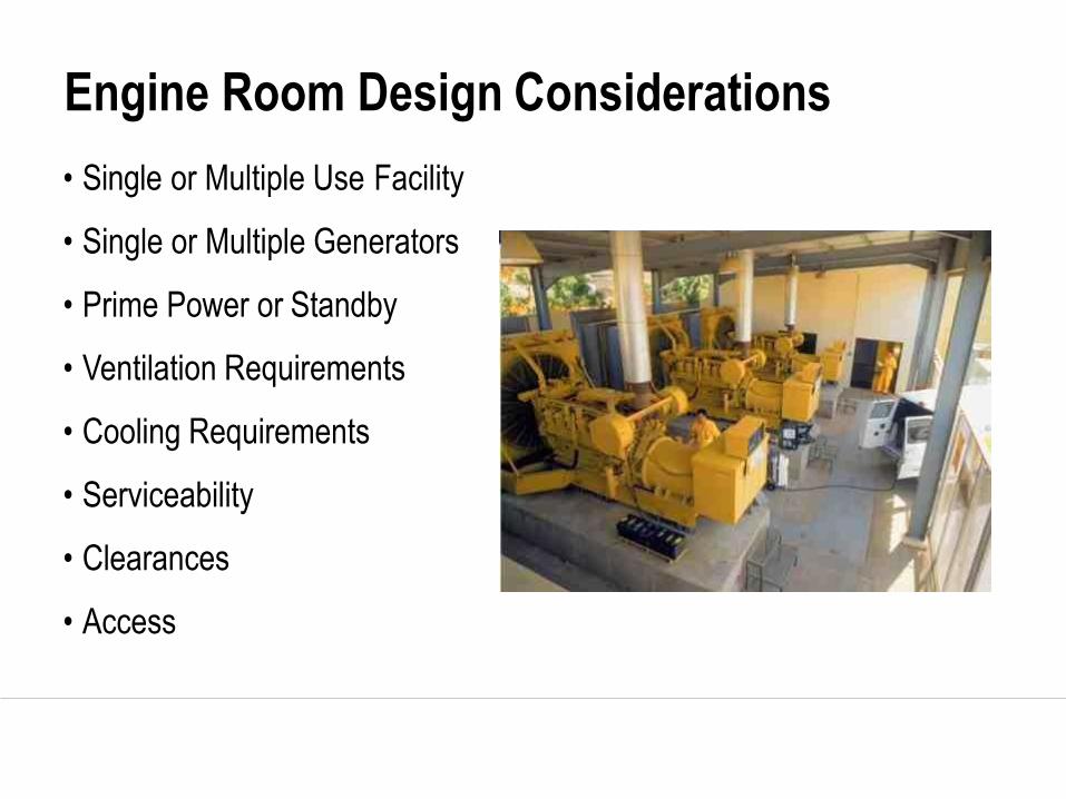
Engine Room Design Considerations
• Single or Multiple Use Facility
• Single or Multiple Generators
• Prime Power or Standby
• Ventilation Requirements
• Cooling Requirements
• Serviceability
• Clearances
• Access
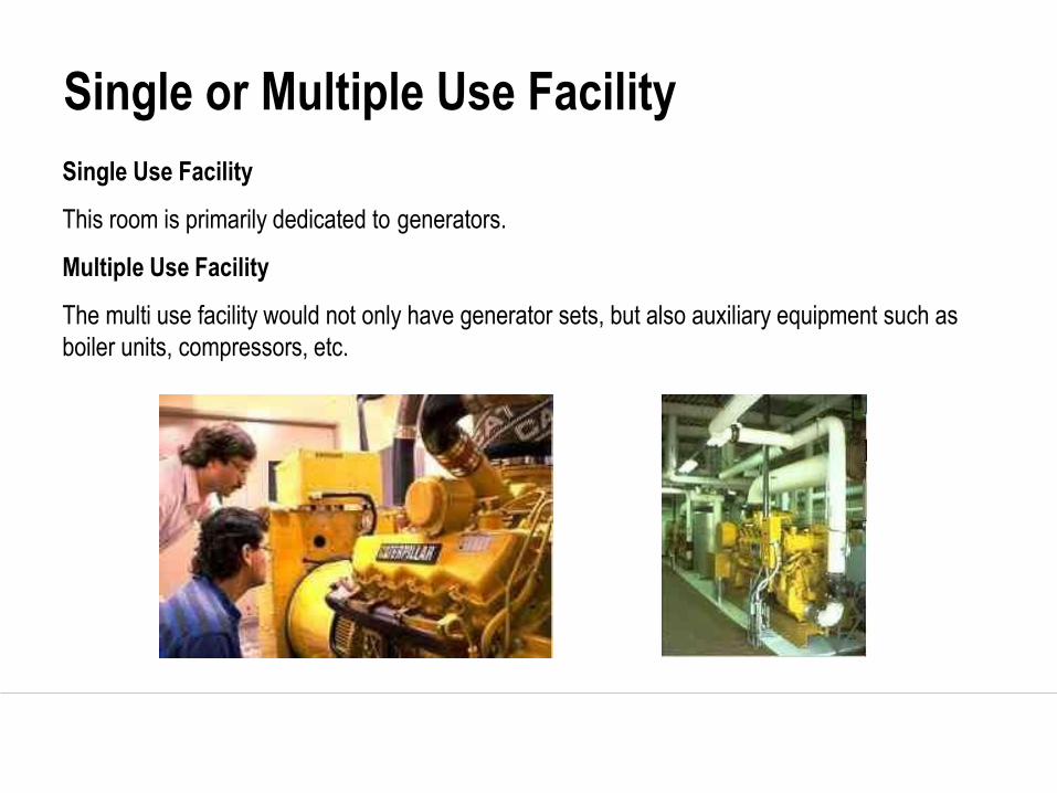
Single or Multiple Use Facility
Single Use Facility
This room is primarily dedicated to generators.
Multiple Use Facility
The multi use facility would not only have generator sets, but also auxiliary equipment such as
boiler units, compressors, etc.

• Location
Prime or Standby

Serviceability

Service Convenience
• Compressed Air
• Ventilation Air
• Water
• Emergency Wash Station
• Fire Suppression System
• Cable Routing
• Load Testing

Clearances
• Lifting Capabilities
• Overhead Clearances
• Side Clearances
• Front and Rear
Clearances
• Underneath Clearance
• Electrical Connections

Access
• Door Width
• Access for Routine
Maintenance
• Major Repair
• Service Elevator

Several Other Considerations
• Emergency/Rental Generator
• Expansion (future genset)
• Installation Considerations - Lift Points
• Total Package Weight
• Engine Storage
• Removing Moisture in Generators
• Flooring Considerations
• Rooftop Installations
• Fire & Explosion Prevention
• Lines, Tubes & Hoses
Page 14
Electric Power | Marine | Oil & Gas CATERPILLAR CONFIDENTIAL: GREEN
Electric Power | Marine | Oil & Gas
Air Intake Systems

• Dirt and debris ingested into the engine are a major source of wear on
moving engine parts.
• The air intake is a significant path for dirt and debris to enter the
engine.
• Sources of dirt and debris in the air intake include:
– Materials left from initial fabrication and assembly of ducts
– Filter changes
– Air intake duct leaks
– Environment
Air Cleanliness

Particles in Intake Air
• Particles under 0.001mm (1 micron) diameter have little
effect and will pass out through the exhaust
• Particles from 0.001 – 0.01mm (1-10 microns) diameter have
a measurable effect on the engine
– The average human hair is 0.08mm (80 microns) in diameter
• One teaspoon of 0.125mm (125 microns) diameter dust per
hour will create catastrophic failure of an engine in 24 hours

Air Cleaner Configurations
• Engine mounted
• Remote mounted
• Multiple element
• Multi-stage (Precleaners)

• May be a requirement of the site configuration
• Best practice to leave engine-mounted air cleaners on the engine and
route ducts from them
• For remote-mounted air cleaners,
ducts must be completely sealed
to ensure all intake air is drawn
through the filter elements
Air Intake Ducts

• Varies according to engine model,
rating and fuel
• Provided on technical data sheet in
both volumetric and mass flow terms
• Establishes total flow
requirement for use in
design of the site air
intake system
• Used in restriction
calculations
Combustion Air Flow Requirements

Page 20
Electric Power | Marine | Oil & Gas CATERPILLAR CONFIDENTIAL: GREEN
Electric Power | Marine | Oil & Gas
Cooling Systems

Engine Heat Balance
Internal Heat
~ 25% - 35%
Mechanical Work
30%-40%
Exhaust Energy
~ 30%-35% Radiation ~ 5%

Review of the Basics
Internal heat is removed by:
– Jacket water
– Oil cooler
– Aftercooler
Oil cooler heat load is included in the jacket water heat load on
diesel engines and in the aftercooler heat load on most gas
engines.

Review of the Basics
Cooling system is defined by how the aftercooler heat
is handled:
– JWAC jacket water aftercooled
– SCAC separate circuit aftercooled
– ATAAC air to air aftercooled
– Two stage aftercooler (JWAC+SCAC)
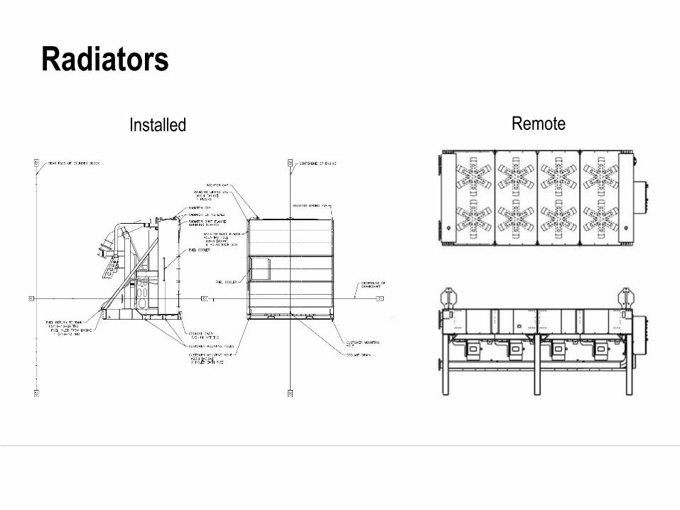
Radiators
Installed Remote

Radiator Height Limits
If more than 57ft vertical
distance from JW pump to
highest point in cooling circuit,
a hot well or heat exchanger is needed to
keep static head pressure below seal limits.

– Try to design room to ½”
H2O restriction
– Plan cooling at ¾” H2O
restriction
• Walls at the air exit
should be 2 fan
diameters or more
away from the radiator
• Louvers typically
require an additional
25-95% opening,
heavy duty bird screen
material, 20-40%
Radiator Air Flow

Radiator Sizing
Need to Know:
– Heat rejection to JW and AC
– Radiant heat added to room
– Room air restriction (if installed radiator)
– Line loss and pump flow rate (if remote radiator)
– Site altitude
– Max ambient temperature

Heat Rise
• Heat Rise - Potential temp rise as intake air moves across gen-set
Example for Caterpillar Diesel Engines:
– Tier 2 engine in a power room: 4oC heat rise
– Tier 4 engine with CEM in a power room: 6oC heat rise
– Tier 2 engine in an enclosure: 7oC heat rise
• THESE ARE MINIMUM VALUES
• When specifying, make sure to
clarify location of ambient temp
or specify cooling
system capability including
heat rise.

Line Restriction
– Always keep external restriction between the
limits shown for the pump in technical
information
– Too much restriction
• Too little flow to cool the engine
• Cavitation that ruins the pump
– Too little restriction
• Too much velocity erodes the cooling system

Venting
– Vent lines or air release valves are needed at every air trap point.
– Vent lines need to be constantly rising until they reach the highest point in the system.
– Air release valves use a float and spring to keep the system closed until steam builds
up in a cavity.

Page 31
Electric Power | Marine | Oil & Gas CATERPILLAR CONFIDENTIAL: GREEN
Electric Power | Marine | Oil & Gas
Exhaust Systems

Exhaust System Considerations
• Minimize back pressure
• Reduce noise
• Provide adequate clearance
• Ensure proper mounting

Back Pressure
• Target – Half the maximum allowable system back
pressure
• Common Culprits
– Exhaust pipe diameter
– Sharp bends
– Exhaust pipe length
– Silencer resistance
• Calculate and Measure

Noise Reduction
• Determine Attenuation Level
– Residential
– Critical
– Supercritical
• Selecting a Silencer
– Balance sound attenuation with back pressure
– Space, Cost, Appearance

Clearance and Mounting
• Clearance
– Overhead cranes
– Minimum 9 inches from combustible materials
– Air intake
• Mounting
– Flexible connections
– Weight support

Page 36
Electric Power | Marine | Oil & Gas CATERPILLAR CONFIDENTIAL: GREEN
Electric Power | Marine | Oil & Gas
Fuel Systems
Diesel Fuel Supply System
• Fuel Storage System
• Fuel Transfer System
• Fuel Filtration System

Fuel Storage System
• Main Tank
– Sizing Rule of Thumb:
Fuel Consumption Rate x Hours Between Refills » (at 100% load factor depending on application)
– 660 Rule
• Day Tank
– Required when main fuel tank is:
• Same level, > 50 ft away
• > 12 ft below engine
• Above engine fuel injectors

Fuel Transfer System
• Fuel Pump Capability and Design Considerations
– Vertical distance from tank to pump
– Internal piping system losses
– Elevation
• Routing
– Avoid hot surfaces
– Avoid formation of traps
– Low to the ground

Fuel Filtration System
• Engine fuel filters must never be removed or
bypassed
• Removal of water and sediment
– Water separator
– Coalescing filter
– Centrifuge

Page 41
Electric Power | Marine | Oil & Gas CATERPILLAR CONFIDENTIAL: GREEN
Electric Power | Marine | Oil & Gas
Engine Room Ventilation

Ventilation
• Remove Radiant and Convection Heat
– Genset and Switchgear performance
– Adequate conditions for personnel
• Engine Room Temperature Rise
– 8.5oC to 12.5oC
– Never exceed 49oC
• Air Velocity
– 1.5 m/s in working areas

Ventilation Considerations
• Direction
– Cool, dry, clean air
– Low entry
– Horizontal air flow
– Generator first

Ventilation Considerations
• Routing
– Entry as far and low as possible
– Discharge as high as possible
– Do not blow cool air toward hot engine components

Type 1 Ventilation

Type 2 Ventilation

Type 3 Ventilation

Type 4 Ventilation

Incorrect Flow Single Engine

Multiple Engine Arrangement

Incorrect Ventilation

Required Air Flow
– Engine room ventilation
can be estimated by the
following formula,
assuming 38oC (100oF)
ambient air temperature:

Page 53
Electric Power | Marine | Oil & Gas CATERPILLAR CONFIDENTIAL: GREEN
Electric Power | Marine | Oil & Gas
Foundations & Isolation

Functional Requirements for Foundations
• Support total weight (mass) & dynamic loading of
equipment, accessory equipment and fluids (coolant, oil
and fuel)
• Maintain alignment between engine, driven equipment, and
accessory equipment
• Isolate equipment vibration from surrounding structures

Base Material
• Material supporting the foundation must carry the
total weight
– Firm level soil, gravel, or rock
– Fine clay, loose sand, or sand near ground water level
• Seasonal changes
– Extend foundations below the frost line

Concrete Foundations
• Avoid excessively thick bases
• For paralleled units foundation must
withstand twice the weight
• Minimum 12 inch edge clearance
• Mass no less than mass of
equipment
• Depth to attain minimum weight
𝐹𝐷 = 𝑊 ÷ (𝐷 × 𝐵 × 𝐿)
FD = Foundation Depth
W = Total Weight of Equipment
D = Density of Concrete
B = Foundation Width
L = Foundation Length

Functional Requirements for Package
Isolators
• Limit vibrations transmitted from genset to foundation
• Ensure that package rigid body vibration modes stay clear of
engine excitation frequencies
• Correct for small variations in foundation surface flatness
– Generally, isolators used on electric power gensets can not correct
for foundation flexure under dynamic loads!

Isolators
• Many types
– Rubber
– Gravel or Sand (Bulk Isolation)
– Spring

Summary
• Engine Room Design
• Air Intake Systems
• Cooling Systems
• Exhaust Systems
• Fuel Systems
• Engine Room Ventilation
• Foundations & Isolation

Questions ?