electric part-turn actuators - process valve solutions sg.pdf · auma’s electric part-turn...
TRANSCRIPT
Electric part-turn actuators
Product description
SG 05.1 – SG 12.1SGR 05.1 – SGR 12.1
SGExC 05.1 – SGExC 12.1
ISO 9001ISO 14001
Certificate Registration No.12 100 426912 104 4269

2
Part/turn valves find applications inmany industries as shut-off devicesand increasingly to control the flow.Without automation the smooth func-tion of industrial processes would beimpossible. AUMA’s electricpart-turn actuators play an importantrole in this case. For part-turn valveswith a nominal diameter of approx.DN 40 and above, AUMA part-turnactuators from the SG 05.1 –SG 12.1 range are the best automa-tion solution.
AUMA is a leading manufacturer ofelectric actuators. More than 40years’ experience in conjunction withthe innovative spirit of our engineersare the sound basis for constantimprovement and further develop-ments.
AUMA offer a wide range of actua-tors which fulfils all the usual require-ments of valve automation.Multi-turn actuators from 10 to32,000 Nm, part-turn actuators from25 to 360,000 Nm or linear thrustunits from 4 to 217 kN. All kinds ofvalves can be automated and oper-ated by rotary and linear movement.
Sales support and after sales serviceare provided worldwide by regionaloffices, service centres, AUMA sub-sidiaries and representatives. Thisensures that experienced salesengineers and qualified service tech-nicians are close to the customer.They are prepared for responding toenquiries, executing orders or fur-nishing after-sales service.
Table of contents
Applications 3Equipment/ Summary of functions 5Equipment/ functions 6
Type designation 6Open-close duty 6Modulating duty 7Comparison short-time and intermittent duty 7Adjustable swing angle 8Seating 8Adjustable torques 9Overload protection against torque peaks 9DUO limit switching/ intermediate position switches (option) 10Limit and torque switches 10Magnetic limit and torque transmitter (MWG) (option) 11Non-intrusive setting (option) 12Position/ torque feedback signal (option) 12Running indication (option) 13Heater 13
Design principle 14Equipment/ functions 16
Motors 16Operating times 16Motor protection 17
Interfaces 18Electrical connection 18Wiring diagrams 20Valve attachment 20Coupling 20
Integral controls 21Integral controls (option) 21Which type of controls? 22Advantages of integral controls (option) 23
Ambient conditions 24Enclosure protection 24Corrosion protection/ Colour 24Ambient temperatures 24Explosion protection 25Lifetime 25Mounting positions 25
Other information 26EU-Directives 26Functional tests 26Further literature 26
Index 27
We reserve the right to alter data according to improvements made.Figures and diagrams are not binding.

3
Applications
AUMA part-turn actuators areemployed wherever an automatedrotatry movement of 360° or lessdriven by an electric motor isrequired. Examples are valves suchas butterfly valves and ball valves.
Water/ Waste-water
Water works Sewage treatment Pump stations
Others Air conditioning and ventilation Ship building industry Steel mills Cement plants
Energy Power plants Air pollution control District heating
Chemicalindustry
Chemical industry Petrochemical industry Pharmaceutical industry
Food industry Breweries Dairies Sugar industry

4
Versions
Definition of part-turnactuators according toISO 5211
A part-turn actuator is an actuator(actor), which transmits a torque tothe valve for less than one full revolu-tion. It need not be capable of with-standing thrust.
Part-turn actuator withAUMA MATIC integralcontrols
Part-turn actuator withAUMATIC controls onwall bracket

5
Equipment/ Summary of functions
Standard Option
SG05.1 – 12.1
SGR05.1 – 12.1
SGExC05.1 – 12.1
Descriptionon page
Equ
ipm
ent/
func
tions
Open-close duty 6Modulating duty 7Swing angle adjustable 8,14Mechanical end stops 14Seating 8
– Limit seating 8
– Torque seating 8Overload protection 9DUO (Four train gear) limit switching 10Limit and torque switches 10
– Tandem switch 10
– Triple switch 10
– Switches with gold plated contacts 10Magnetic limit and tor que transmitter (MWG) 11Non-intrusive setting 12Position feedback/ torque feedback signal 12Mechanical position indicator 14Blinker transmitter for running indication 13Operating time adjustable 16Manual operation 15Heater
– in switch compartment 13
– Motor heater 13Motors 15, 16
– 3-phase AC motors 15, 16
– 1-phase AC motors 15, 16
– DC motors 15, 16Motor protection 17
– Thermoswitches 17
– PTC thermistor 17Integral controls 21 - 23
Inte
rfac
es
Electrical connections 14, 18, 19
– AUMA plug/ socket connector 18, 19
– Double sealed 18
– Plug/ socket connector for explosion-proof actuators 18, 19
– Plug-in terminal connection 18, 19
– Plug cover in special versions 19Valve attachment according to ISO 5211 15, 20
– Coupling 15, 20
– Coupling with bore 20
Ser
vice
cond
ition
s
Ambient conditions 24– Enclosure protection IP67 24
– Enclosure protection IP68 24
– High temperature version 24
– Low temperature version 24
– Corrosion protection KN 24
– Corrosion protection KS, KX 24
– Version with cast iron housing 24Explosion protection 24, 25EU Directives 26Functional tests 26

6
Equipment/ functions
Type designation
Version for modulating duty
Explosion-proof part-turn actuator acc. to ATEX Directive 94/9/ EC
SGRExC 05.1
Size (standard flange size according to EN ISO 5211)
Device generation (SG x.2 for ship building, SG x.3 for lower torques)
Open-close duty
Type of duty for part-turnactuators for open-close duty(SG, SGExC)
AUMA part-turn actuators SG foropen-close service are rated forshort-time duty S2 - 15 min. Theexplosion-proof version SGExC arerated for S2 - 10 min. Description ofthe types of duty on page 7.
t run max = 15 min (30 min)
trunVal
vepo
sitio
n
t
Typical operation process in OPEN-CLOSE duty
Input
Valve
Actuatorfor open-close duty
The usual valve positions inopen-close duty are the end posi-tions OPEN and CLOSED. Uponreceiving an appropriate commandthe actuator moves the valve to oneof the two end positions or, if neces-sary, to a pre-defined intermediateposition.
The valves are operated relativelyseldom, the time intervals can spanbetween a few minutes up to severalmonths.
7
Equipment/ functions
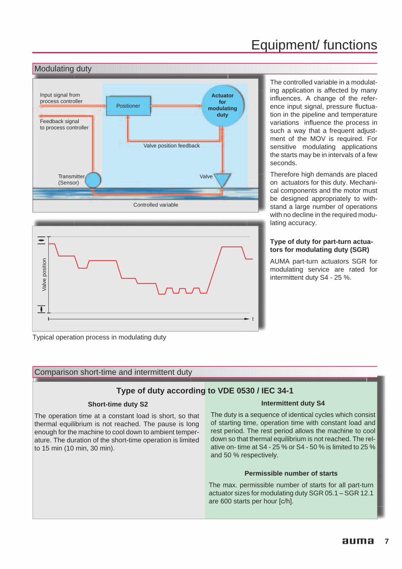
Modulating duty
Input signal fromprocess controller
Feedback signalto process controller
Transmitter(Sensor)
Valve
Valve position feedback
Controlled variable
Actuatorfor
modulatingduty
Positioner
t
Val
vepo
sitio
n
Typical operation process in modulating duty
The controlled variable in a modulat-ing application is affected by manyinfluences. A change of the refer-ence input signal, pressure fluctua-tion in the pipeline and temperaturevariations influence the process insuch a way that a frequent adjust-ment of the MOV is required. Forsensitive modulating applicationsthe starts may be in intervals of a fewseconds.
Therefore high demands are placedon actuators for this duty. Mechani-cal components and the motor mustbe designed appropriately to with-stand a large number of operationswith no decline in the required modu-lating accuracy.
Comparison short-time and intermittent duty
Type of duty according to VDE 0530 / IEC 34-1
Short-time duty S2
The operation time at a constant load is short, so thatthermal equilibrium is not reached. The pause is longenough for the machine to cool down to ambient temper-ature. The duration of the short-time operation is limitedto 15 min (10 min, 30 min).
Intermittent duty S4
The duty is a sequence of identical cycles which consistof starting time, operation time with constant load andrest period. The rest period allows the machine to cooldown so that thermal equilibrium is not reached. The rel-ative on- time at S4 - 25 % or S4 - 50 % is limited to 25 %and 50 % respectively.
Type of duty for part-turn actua-tors for modulating duty (SGR)
AUMA part-turn actuators SGR formodulating service are rated forintermittent duty S4 - 25 %.
Permissible number of starts
The max. permissible number of starts for all part-turnactuator sizes for modulating duty SGR 05.1 – SGR 12.1are 600 starts per hour [c/h].

8
Equipment/ functions
Adjustable swing angle
During manual operation the swingangle is limited via the internal endstops. If the customer requirementshave not been mentioned in theorder, the actuator is supplied with aswing angle of 90° The swing anglemay be subsequently adjustedwithin a range of 80° – 110°. Theoperating time is extended orreduced accordingly.
Other swing angle ranges(option)
On request the part-turn actuatorsmay be supplied with different swingangle ranges.
The following swing angle rangesare available:
30° – 40° 40° – 55° 55° – 80° 80° – 110° (standard) 110° – 160° 160° – 230° 230° – 320°
Seating
Limit seating
The actuator runs at nominal output speed up to the settripping point P. Due to the high reduction ratio and theconsequently low output speeds (3.75 rpm at the shortestoperating time 4 s for 90°) the overrun may be ignored.
Torque seating
After starting from the end position OPEN, the actuatorruns in direction CLOSE. In end position CLOSED thetorque increases within the valve seat until the actuator isautomatically switched off after reaching the set value.
Travel
Spe
ed
P
CLOSEDOPEN CLOSEDOPEN
Travel
Set tripping torque
Torq
ue
Depending on the design of the valveto be operated, end position switch-ing either limit seating, i.e. by mea-suring the valve travel completed, ortorque seating, i.e. after reaching adefined torque. For this purpose, the
actuator is equipped with two inde-pendent measuring systems, i.e.limit switching and torque switching.
The type of seating has to be taken in
account both when setting the actua-tor and in the actuator control. How-ever, the processing of signals forthe two types of seating differs.

9
Equipment/ functions
Adjustable torques
Minimum and maximum tripping torques for part-turn actuators for open-close duty
Size SG 05.1 SG 07.1 SG 10.1 SG 12.1
min. [Nm] 100 120 250 500
max. [Nm] 150 300 600 1 200
Torques for part/turn actuators for modulating duty
Size SGR 05.1 SGR 07.1 SGR 10.1 SGR 12.1
min. tripping torque [Nm] 100 120 250 500
max. tripping torque [Nm] 150 300 600 1 200
Torque for modulating [Nm] 50 100 200 400
Overload protection against torque peaks
The torque switching, used fortorque seating in the end position(see page 8), serves as overloadprotection for the entire travel, evenin the case of limit seating.
If excessive torque builds up at theobturator in an intermediate position,e.g. due to a trapped object, thetorque switching trips after reachingthe set tripping torque.
After the controls have processedthe torque switch signal accordingly,the motor will be switched off. As aresult, valve and actuator are pro-tected from damage.
If the limit switch signals are pro-cessed accordingly in the controls,you can distinguish between a nor-mal torque switch tripping at the end
positions and tripping in an interme-diate position (fault) caused byover-torque.
CLOSEDOPEN
Travel
Set tripping torque
Torq
ue
10
Equipment/ functions
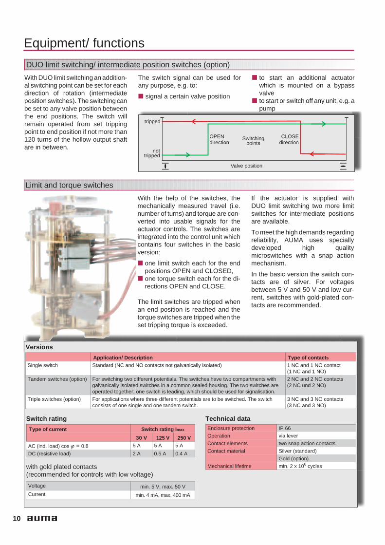
DUO limit switching/ intermediate position switches (option)
With DUO limit switching an addition-al switching point can be set for eachdirection of rotation (intermediateposition switches). The switching canbe set to any valve position betweenthe end positions. The switch willremain operated from set trippingpoint to end position if not more than120 turns of the hollow output shaftare in between.
The switch signal can be used forany purpose, e.g. to:
signal a certain valve position
to start an additional actuatorwhich is mounted on a bypassvalve
to start or switch off any unit, e.g. apump
tripped
Switchingpoints
OPENdirection
CLOSEdirection
Valve position
nottripped
Limit and torque switches
With the help of the switches, themechanically measured travel (i.e.number of turns) and torque are con-verted into usable signals for theactuator controls. The switches areintegrated into the control unit whichcontains four switches in the basicversion:
one limit switch each for the endpositions OPEN and CLOSED,
one torque switch each for the di-rections OPEN and CLOSE.
The limit switches are tripped whenan end position is reached and thetorque switches are tripped when theset tripping torque is exceeded.
If the actuator is supplied withDUO limit switching two more limitswitches for intermediate positionsare available.
To meet the high demands regardingreliability, AUMA uses speciallydeveloped high qualitymicroswitches with a snap actionmechanism.
In the basic version the switch con-tacts are of silver. For voltagesbetween 5 V and 50 V and low cur-rent, switches with gold-plated con-tacts are recommended.
Versions
Application/ Description Type of contact s
Single switch Standard (NC and NO contacts not galvanically isolated) 1 NC and 1 NO contact(1 NC and 1 NO)
Tandem switches (option) For switching two different potentials. The switches have two compartments withgalvanically isolated switches in a common sealed housing. The two switches areoperated together; one switch is leading, which should be used for signalisation.
2 NC and 2 NO contacts(2 NC und 2 NO)
Triple switches (option) For applications where three different potentials are to be switched. The switchconsists of one single and one tandem switch.
3 NC and 3 NO contacts(3 NC and 3 NO)
Switch rating
Type of current Switch rating I max
30 V 125 V 250 V
AC (ind. load) cos ϕ = 0.8 5 A 5 A 5 A
DC (resistive load) 2 A 0.5 A 0.4 A
with gold plated contacts(recommended for controls with low voltage)
Voltage min. 5 V, max. 50 V
Current min. 4 mA, max. 400 mA
Technical dataEnclosure protection IP 66
Operation via lever
Contact elements two snap action contacts
Contact material Silver (standard)
Gold (option)
Mechanical lifetime min. 2 x 10⁶ cycles

11
Equipment/ functions
Magnetic limit and torque transmitter (MWG) (option)
The magnetic limit and torque trans-mitter converts the mechanical val-ues of limit and torque into continu-ous electronic signals.
The simultaneous use of integralcontrols which evaluate the signalsis a prerequisite for the use of theMWG. This variant does not require
any switches for limit positions ortorque.
Actuators with MWG have the follow-ing advantages.
Non-intrusive setting is possible(see page 12)
A torque signal is permanentlyavailable. It can be used forswitching off at the set trippingtorque. It can also be transmittedfor external use, for example fortorque monitoring at the valve.
Absolute travel measurement –without battery
The valve position is determinedusing a so called multi-turn-absoluteencoder.Four shafts, each with a ratio of 8:1,are used to convert the travel into anelectronic signal. Each valve posi-tion is assigned an unambiguouscombination of the 4 shaft positions.Magnets and hall sensors registerthe shaft positions electronically.
As soon as the power supply hasbeen restored after a power failure,the current valve position is immedi-ately available; a reference opera-tion is not required. Position changesdue to manual operation duringpower failure are registered by theMWG even without supply voltage. Abattery is not required.
Torque – continuously available
The proven design of the slidingworm provides the mechanical prin-ciple of torque sensing. A torque atthe output drive results in an axialmovement of the sliding wormagainst the spring action. With alever, the axial movement is trans-formed into a rotary movement. Hallsensors convert this movement intoan electronic signal.
Travel/ position signalto the controls
Torque signalto the controls

12
Equipment/ functions
Non-intrusive setting (option)
If the actuator is equipped witha magnetic limit and torquetransmitter (see page 11) andAUMATIC integral controls (see
page 22) the actuator can be setnon-intrusively. This means that the
parameters can be set without hav-ing to open the actuator. Therebyseveral advantages are achieved:
No tools are required for setting. The actuator need not be opened
again after the electrical connec-tion is completed. The electronicand mechanical components inthe housing are well protectedfrom ingress of water and dust.
The actuator can be set in poten-tially explosive atmospheres,without affecting the explosionprotection.
Position/ torque feedback signal (option)
If the actuator is equipped with anMWG and AUMATIC integral con-trols, the valve position and thetorque available in the valve are canbe used as output signals. Even ifthere is no MWG installed in the actu-ator, the position of the valve can betransmitted as a continuous signalfor remote position indication.
Position feedback is provided as ananalogue feedback signal by:
Precision potentiometer Electronic position transmitter
RWG.
Electronic position transmitterRWG
The actual position value is transmit-ted by a potentiometer and trans-formed by electronics into a currentsignal. Zero and span of the feed-back signal can be easily adjusted bytrimmer potentiometers.
Inverse operation of the RWG is pos-sible.
Technical data potentiometer
Precision potentiometer Precision potentiometer intandem version
Linearity ≤ 1 %
Output 0.5 W
Resistance (standard) 0.2 kΩ 0.2/0.2 kΩ
Resistance (option) 0.1 kΩ, 0.5 kΩ, 1.0 kΩ,5.0 kΩ
0.5/0.5 kΩ, 1.0/1.0 kΩ,5.0/5.0 kΩ, 0.2/5.0 kΩ
Technical data RWG
Output signal- 2-wire system- 3- or 4-wire system
4 – 20 mA0/4 − 20 mA
Supply voltage 24 V DC ±15% smoothed
Lifetime min. 5 x 10⁶ operations
1006000
20Signalin mA
4
Travel in %
Power supply unit for withoutintegral controls
For the voltage supply of all positiontransmitters we recommend theAUMA power supply unit PS 01.However, this unit must not be usedin potentially explosive atmospheresor for intrinsically safe electriccircuits.

13
Equipment/ functions
Running indication (option)
As an option the actuators are avail-able with a blinker switch installedwhich can be used for the runningindication. The contacts are avail-able at the electrical connection.
Rating
Type of current Switch rating Imax
30 V 125 V 250 VAC 5 A 5 A 5 A
DC 2 A 0.5 A 0.4 A
Heater
Heater in switch compartment(standard)
Condensation in the actuator is pos-sible due to wide fluctuation of theambient temperature. The heaterintegrated in the control unit pre-vents this in general.
The heater is rated for continuousduty. Therefore it should always beenergized, but at the very least whenthe actuator is not operating.
Technical data for heater in switch compartment
Heater for actuatorswithout integral controls
Heater for actuators withintegral controls
Heating element self-regulating PTC element Resistance type heater
Voltage ranges 110 V – 250 V DC/AC24 V – 48 V DC/AC380 V – 400 V AC
24 V DC/AC(internal supply)
Output 5 W – 20 W 5 W
Motor heater(option)
For operation in extremely low tem-peratures AUMA strongly recom-mends the use of a motor heater.This applies to actuators in extremelow temperature version from– 50 °C. The heater prevents actua-tor starting problems caused byextremely cold temperatures.
14
Design principle
3
1
4
6
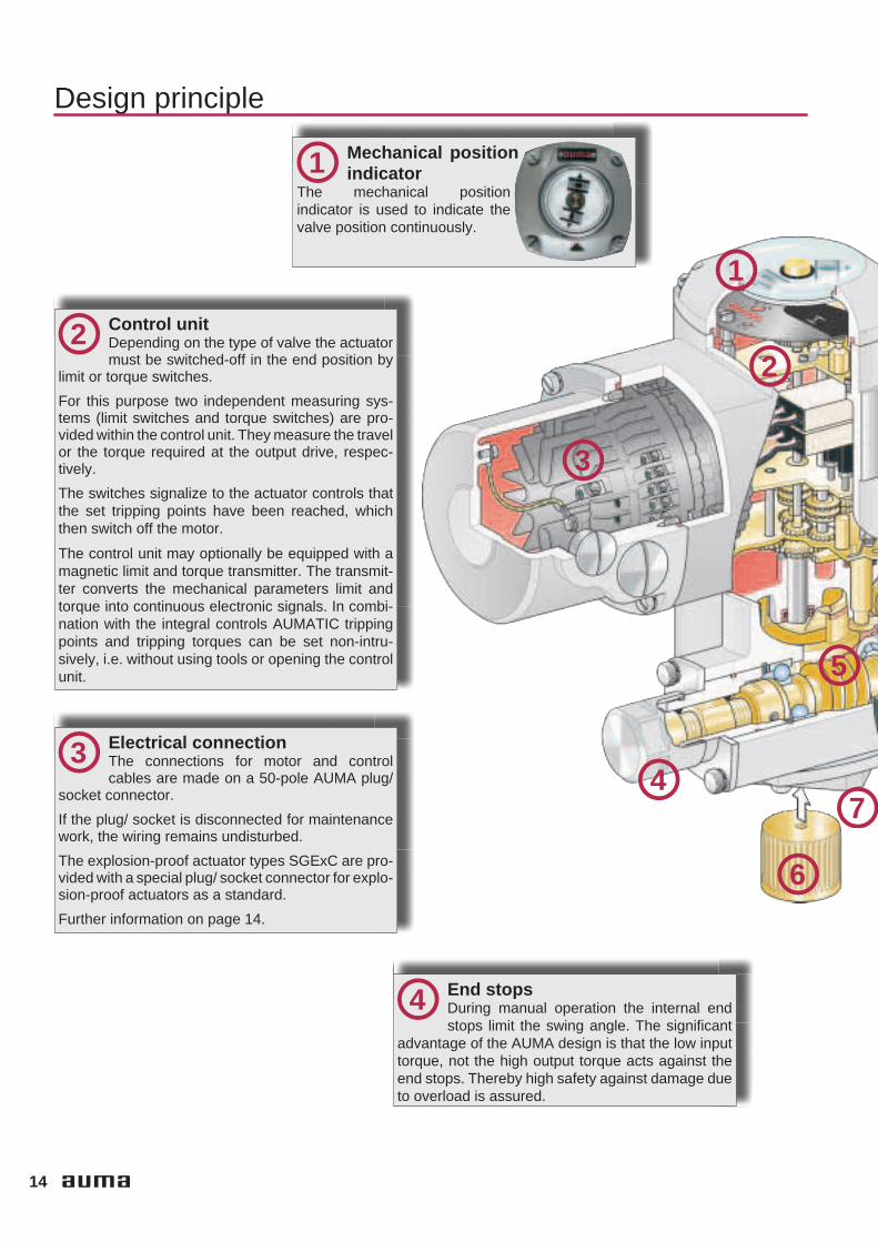
Mechanical positionindicator
The mechanical positionindicator is used to indicate thevalve position continuously.
1
Control unitDepending on the type of valve the actuatormust be switched-off in the end position by
limit or torque switches.
For this purpose two independent measuring sys-tems (limit switches and torque switches) are pro-vided within the control unit. They measure the travelor the torque required at the output drive, respec-tively.
The switches signalize to the actuator controls thatthe set tripping points have been reached, whichthen switch off the motor.
The control unit may optionally be equipped with amagnetic limit and torque transmitter. The transmit-ter converts the mechanical parameters limit andtorque into continuous electronic signals. In combi-nation with the integral controls AUMATIC trippingpoints and tripping torques can be set non-intru-sively, i.e. without using tools or opening the controlunit.
22
Electrical connectionThe connections for motor and controlcables are made on a 50-pole AUMA plug/
socket connector.
If the plug/ socket is disconnected for maintenancework, the wiring remains undisturbed.
The explosion-proof actuator types SGExC are pro-vided with a special plug/ socket connector for explo-sion-proof actuators as a standard.
Further information on page 14.
3
End stopsDuring manual operation the internal endstops limit the swing angle. The significant
advantage of the AUMA design is that the low inputtorque, not the high output torque acts against theend stops. Thereby high safety against damage dueto overload is assured.
4
7
5

15
Design principle
8
9
GearingThe well proven principle of worm gearing,combined with a planetary gear, is used to
reduce the motor speed to the required actuator out-put speed. Self-locking is achieved by the wormgearing.
The gear housing is filled with lubricant for the wholelifetime. A change of grease or re-lubrication is notnecessary.
5
CouplingThe separate coupling facilitates the assem-bly of the actuator. It is placed on the valve
shaft and secured against axial movement. Subse-quently the actuator is fitted on the valve flange(Refer also to page 20).
6
Valve attachmentThe valve attachment is according to EN ISO5211. On request, special connections are
available.
The gearbox can be positioned on the valve at every90°.
7
Manual operationFor commissioning or in an emergency thepart-turn actuator can be operated with the
handwheel. Pull the handwheel until it disengages.The manual operation acts on the worm shaft due toan over-riding gear arrangement. The sliding wormwhich is used to determine the torque is located onthe handwheel shaft.
8
MotorAn especially high starting torque is fre-quently required to unseat valves from the
end position. The motors developed by AUMA fulfilthis basic requirement.Apart from the predominantly used 3-phase ACmotors, the actuators may also be equipped with1-phase AC motors. When using actuators with1-phase motors, the operating time can be adjusted.
The motor is connected via an internal plug/ socketconnector. This enables quick exchange of themotor, e.g. for change of output speed.
Further information on page 16.
9

16
Equipment/ functions
Motors
Part-turn actuators SG 05.1 – SG12.1 may be equipped with 3-phaseAC motors (standard), 1-phase ACmotors (option), or DC motors(option). Part-turn actuators for mod-
ulating duty SGR are only availablewith 3-phase AC motors. For actua-tors with 3-phase AC motors, theoperating time may only be reachedby replacing the motor or the plane-
tary gear. For actuators with 1-phaseAC motors, the operating time maybe adjusted on site (see below).
Standard voltages/ frequencies
3-phase AC motors
Voltage 1) [V] 220 230 240 380 400 415 440 460 480 500
Frequency [Hz] 50 50 50 50 50 50 60 60 60 50
1-ph AC motors
Voltage [V] 110 – 120 220 – 240
Frequency [Hz] 50/ 60 50/ 60
DC motors
Voltage [V] 24 110 2201) Permissible fluctuations ± 10 %
Overvoltage may result in excessive temperature rise in the motor windings. In case of undervoltage the motor torque decreases in the ratio ofthe square of undervoltage divided the standard voltage. Larger voltage variations have therefore to be considered when sizing the actuator.
Operating times
If the actuators are equipped with thestandard 3-phase AC motor, theoperating time is invariably con-nected to the supply frequency andthe reduction ratio. The operatingtime may only be subsequentlychanged by replacing the motor orthe planetary gear.
For part-turn, open-close duty actua-tors optionally equipped with a1-phase AC motor, the operatingtime may be adjusted within the setlimits. Part-turn SGR actuators formodulating duty are only availablewith 3-phase AC motors.
Operating times for a swing angle of 90°
Size SG 05.1 SG 07.1 SG 10.1 SG 12.1
with 3-phase AC motor at50 Hz [s]
4/ 5,6/ 8/ 11/ 16 /22/ 32
5,6/ 8/ 11/ 16/ 22/32
11/ 16/ 22/ 32/ 45/63
22/ 32/ 45/ 63
with 1-phase AC motor at50 Hz [s]
5.6 – 45 11 – 90 11 – 90 22 – 180
with DC motor [s] 5 – 1010 – 20
10 – 1520 – 30
20 – 2540 – 50
30 – 3560 – 70

17
Equipment/ functions
Motor protection
In order to protect the motor againstoverheating thermoswitches or PTCthermistors are embedded in themotor windings of the 3-phase ACand 1-phase AC motors. When inte-grated into the control circuit, theywill protect the motor against dam-age due to excessively high windingtemperature.
Thermoswitches and PTC thermis-tors offer better protection than ther-mal overload relays, since the tem-perature rise is directly measured atthe motor.
The thermoswitches will interrupt thecontrol circuit as soon as a windingtemperature of 140 °C is exceeded.After cooling down to a temperaturebetween 120 °C to 90 °C, the actua-tor can be switched on again.
Important! Failure to integrate themotor protection device into the con-trols voids the warranty for themotors.
If the actuator is equipped with inte-gral controls, the thermoswitchesare automatically integrated.
Delay time
The delay time is the time from thetripping of the limit or torque switchesto the motor power being removed.
To protect the valve against exces-sive peak torques, the delay timeshould be as low as possible. Thisshould be taken into account, espe-cially if the actuators are controlledby a PLC. We recommend a delaytime < 50 ms and to switch off the cor-responding contactor directly by thelimit or torque switch. Longer delay
times are possible provided the out-put speed, output drive type, valvetype and the type of installation areconsidered.
For the AUMA MATIC and AUMATICintegral controls the motor will imme-diately be switched off after trippingof a switch.
Actuator type Thermoswitches PTC thermistorsSG/SGR 05.1 – SG/SGR 12.11)
Standard Option
SGExC 05.1 – SGExC 12.11)Option Standard
1) Also available with integral controls AUMA MATIC or AUMATIC; in this case the PTC trip-ping device is already integrated, if PTC thermistors are used.
Rating of the thermoswitches
AC voltage(250 V AC)
Switch ratingImax
cos ϕ = 1 2.5 A
cos ϕ = 0.6 1.6 A
DC voltage Switch ratingImax
60 V 1 A
42 V 1.2 A
24 V 1.5 A
140 °C
90 °C
115 °C
Mot
orte
mpe
ratu
re
Time
Reset point
Tripping point

18
Interfaces
AUMA plug/ socket connector
As a standard, the actuators areequipped with an AUMA plug/socket connector for motor andcontrol cables. This applies whetherthe actuator is equipped with inte-gral controls or not.
The significant advantage of thistype of connection:Once connected, the wiring remainsundisturbed, even if the actuator hasto be removed from the valve, e.g. formaintenance purposes.
Electrical connection
Double sealed(option)
The double sealed connection is asealed plug and socket which is fittedbetween the device housing and theplug/ socket connector. Even afterremoving the plug cover or if thecable glands do not seal properly thedevice will be protected against theingress of dust or humidity.
Plug/ socket connector with terminal board for explosion-proof actuators SGExC
Explosion-proof actuators in ver-sions SGExC with or without con-trols are designed with a ‘flameproofenclosure’. The sealed terminalboard of this electrical connectionensures that the flameproof enclo-sure remains undisturbed even if theplug cover has been removed.
The electrical connection betweenthe terminal board and the electric/electronic components within thedevice is provided via a plug/ socketconnector. The advantage of themodular design with plug-in connec-
tion is thereby also provided for explo-sion-proof actuators.
The customer connection compart-ment is designated protection type‘increased safety’.
By means of a protection cover, whichis available as an option, the discon-nected plug may be fitted to a wall toenable the operation of the plantunder explosion-proof conditions.
Plug-in terminal c onnection for explosion-proof actuators SGExC (option)
Contrary to the plug/ socketconnector, the customer connectionis made on terminals which havebeen fitted to a terminal frame. Theconnection compartment has beenenlarged. In terms of explosion pro-tection this connection type has thesame characteristics as the plug/socket connector.
On request, these terminals can alsobe used for non-explosion-proof actu-ators.
By means of a protection cover whichis available as an option, the discon-nected plug may be fitted to a wall toenable the operation of the plantunder explosion-proof conditions.

19
Interfaces
Special connections
For special customer requests plug/socket connectors of specifiedbrands can be used.
The plug cover of the standard ver-sion can be replaced by the followingvariants:
Plug cover with
removable lid enlarged terminal compartment enlarged terminal compartment
and removable lid
Parking frame, protection cover
These parts offer the facility to placethe plug connector, while taken offthe actuator, in a safe location on awall. The open terminal compart-ment at the actuator can be closedwith the protection cover. This pre-vents foreign matter, dust and waterfrom entering the compartment whilethe plug connector is taken off.
Technical dataAUMA plug/ socket connector
No. of contacts max. 6 (3 are available) 1 (leading contact) 50 pins/ socketsDesignation U1, V1, W1, U2, V2, W2 according to VDE 1 to 50Connection voltage max. 750 V – 250 V
Nominal current max. 25 A – 16 A
Type of customer connection Screws Screw for ring lug Screws or crimping (option)Cross section max. 6 mm2 6 mm2 2.5 mm2
Material: Pin/ socket carrier Polyamide Polyamide PolyamideContacts Brass Brass Brass, tin plated or gold plated (option)
Plug/ socket connector/ terminal board for explosion-proof actuators SGExC
No. of contacts max. 3 1 38 pins/ socketsDesignation U1, V1, W1 according to VDE 1 to 24, 31 to 40, 47 to 50Connection voltage max. 550 V – 250 V
Nominal current max. 25 A – 10 A
Type of customer connection Screws Screws ScrewsCross section max. 6 mm2 6 mm2 1.5 mm2
Material: Pin/ socket carrier Araldite/ Polyamide Araldite/ Polyamide Araldite/ PolyamideContacts Brass Brass Brass tin-plated
Plug-in terminal connection for explosion-proof actuators SGExC
Terminals max. 6 (3 are available) 1 (leading contact) 50Designation U1, V1, W1 according to VDE 1 to 50Voltage max. 750 V – 250 V
Current max. 25 A – 10 A
Type of customer connection Screws Screws Cage clamp2)
Cross section max. 10 mm2 10 mm2 2.5 mm2 flexible
Threads for conduit entries 3)
Type Metric (standard) Pg (option)
SG/ SGR 05.1 – 12.14)
SGExC 05.1 – 12.14)2 x M25x1,5; 1 x M20x1,5 2 x Pg21; 1 x Pg13;5
1) Suitable for copper wires. For aluminium wires please contact AUMA.2) Optional with screw connections.3) For delivery, sealed with plugs. Other thread sizes and thread types e.g. metric threads are possible on request.
Cable glands can be supplied on request.4) Also valid for possibly available integral actuator controls.
Technical data Motor power connections 1) Protective earth Control pins
Technical data Motor power connections 1) Protective earth Control pins
Technical data Motor power connections 1) Protective earth Control pins
20
Interfaces
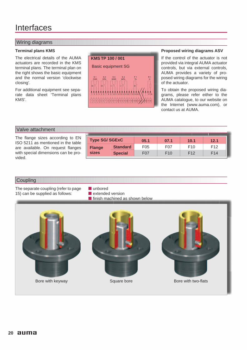
Wiring diagrams
Terminal plans KMS
The electrical details of the AUMAactuators are recorded in the KMSterminal plans. The terminal plan onthe right shows the basic equipmentand the normal version ‘clockwiseclosing’.
For additional equipment see sepa-rate data sheet ‘Terminal plansKMS’.
Proposed wiring diagrams ASV
If the control of the actuator is notprovided via integral AUMA actuatorcontrols, but via external controls,AUMA provides a variety of pro-posed wiring diagrams for the wiringof the actuator.
To obtain the proposed wiring dia-grams, please refer either to theAUMA catalogue, to our website onthe Internet (www.auma.com), orcontact us at AUMA.
KMS TP 100 / 001
Basic equipment SG
Valve attachment
The flange sizes according to ENISO 5211 as mentioned in the tableare available. On request flangeswith special dimensions can be pro-vided.
Type SG/ SGExC 05.1 07.1 10.1 12.1
Flangesizes
Standard F05 F07 F10 F12
Special F07 F10 F12 F14
Coupling
The separate coupling (refer to page15) can be supplied as follows:
unbored extended version finish machined as shown below
Bore with keyway Bore with two-flatsSquare bore

21
Integral controls
Integral controls (option)
withAUMA MATIC
withAUMATIC
Part-turn actuators SG 05.1 – 12.1
22
Integral controls
Which type of controls?
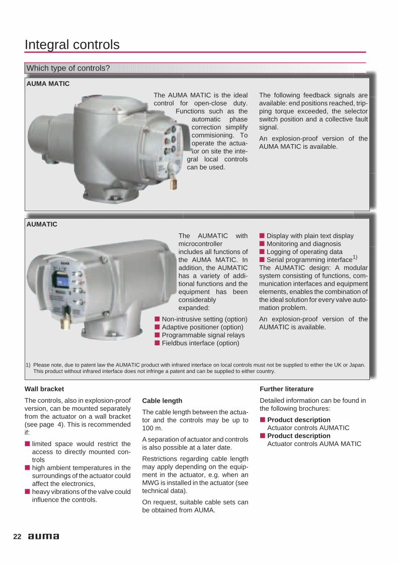
AUMA MATIC
The AUMA MATIC is the idealcontrol for open-close duty.
Functions such as theautomatic phasecorrection simplifycommisioning. Tooperate the actua-tor on site the inte-
gral local controlscan be used.
The following feedback signals areavailable: end positions reached, trip-ping torque exceeded, the selectorswitch position and a collective faultsignal.
An explosion-proof version of theAUMA MATIC is available.
AUMATIC
The AUMATIC withmicrocontrollerincludes all functions ofthe AUMA MATIC. Inaddition, the AUMATIChas a variety of addi-tional functions and theequipment has beenconsiderablyexpanded:
Non-intrusive setting (option) Adaptive positioner (option) Programmable signal relays Fieldbus interface (option)
Display with plain text display Monitoring and diagnosis Logging of operating data Serial programming interface1)
The AUMATIC design: A modularsystem consisting of functions, com-munication interfaces and equipmentelements, enables the combination ofthe ideal solution for every valve auto-mation problem.
An explosion-proof version of theAUMATIC is available.
1) Please note, due to patent law the AUMATIC product with infrared interface on local controls must not be supplied to either the UK or Japan.This product without infrared interface does not infringe a patent and can be supplied to either country.
Wall bracket
The controls, also in explosion-proofversion, can be mounted separatelyfrom the actuator on a wall bracket(see page 4). This is recommendedif:
limited space would restrict theaccess to directly mounted con-trols
high ambient temperatures in thesurroundings of the actuator couldaffect the electronics,
heavy vibrations of the valve couldinfluence the controls.
Cable length
The cable length between the actua-tor and the controls may be up to100 m.
A separation of actuator and controlsis also possible at a later date.
Restrictions regarding cable lengthmay apply depending on the equip-ment in the actuator, e.g. when anMWG is installed in the actuator (seetechnical data).
On request, suitable cable sets canbe obtained from AUMA.
Further literature
Detailed information can be found inthe following brochures:
Product descriptionActuator controls AUMATIC
Product descriptionActuator controls AUMA MATIC

23
Integral controls
e.g. 400 V AC e.g. 400 V AC
Con
trols
Con
trols
Con
trols
O. C. O. C.
O. C.
Con
trol
cab
inet
Process control system
PLC PLC
Fie
ldbu
sm
aste
r
I> I>I> I>
I> I>
Isolatingswitch
SupplyCommandsSignalsFieldbus cable (bidirectional)
Localcontrols
Advantages of integral controls (option)
The aim in developing integral motorcontrols was to enable the customer
to save the high installation costs ofexternal controls. This is highlighted
by the diagram below.
External controls (A)
For actuators to be connected toexternal controls, the following mustbe considered:
All actuator signals, e.g. thetorque and limit switch signals,must be passed on to the externalcontrols in the control cabinet.
The control of the actuators via areversing contactor combinationhas to be implemented and in-stalled in the control cabinet.
The local controls have to be im-plemented and mounted
Integral controls (B)
Actuators with integral controls aresupplied ready for use with local con-trols and switching elements.All electrical components, e.g. limit,torque and thermoswitches, as wellas monitoring elements and possiblyavailable position transmitters areintegrated into the modern controls.This results in the following simplifiedsystems:
No extensive wiring in a controlcabinet is required.
Reliable and correct processing ofthe actuator signals. The immedi-ate reaction of the controls pre-vents excessive torques frombuilding up in the valve
Actuator and controls are ideallyadjusted to each other
Standard wiring diagrams areavailable
Integral controls/Fieldbus (C)
If the actuator controls are integratedin a fieldbus system, then the instal-lation costs are further reduced. Thecommands and signals of all actua-tors (slaves) are transmitted to andfrom the master via a two-wire cableor via optical fibres. The space con-suming input/ output boards, as wellas their associate control cabinetsections, are no longer required.
A B C

24
Ambient conditions
Enclosure protection
Corrosion protection / Colour
KN (standard)
The standard AUMA corrosion pro-tection KN is a high quality coating.This is suitable for outdoor installa-tion and for slightly aggressive atmo-spheres with a low level of pollution.
KS
AUMA recommends this corrosionprotection class when installingdevices in occasionally or perma-nently aggressive atmospheres witha moderate pollutant concentration(e.g. in sewage treatment plants,chemical industry).
KX
AUMA recommends this corrosionprotection class when installingdevices in extremely aggressiveatmospheres with high humidity andhigh pollutant concentration.
Ambient temperatures
Versions SG SGR SGExC
Standard – 25 °C – + 80 °C 1) – 25 °C – + 60 °C – 20 °C – + 40 °C 2)
Low temperature – 40 °C – + 60 °C – 40 °C – + 60 °C – 40 °C – + 40 °C
Extr. low temperature – 50 °C – + 60 °C – – 50 °C – + 40 °C
High temperature 3) 0 °C –+ 120 °C – –
Versions SG SGR SGExC
Standard – 25 °C – + 80 °C 1) – 25 °C – + 60 °C – 20 °C – + 40 °C 2)
Low temperature – 40 °C – + 60 °C – 40 °C – + 60 °C – 40 °C – + 40 °C
Extr. low temperature – 50 °C – + 60 °C – – 50 °C – + 40 °C
High temperature 3) 0 °C –+ 120 °C – –
1) With 3-phase AC motor up to + 80 °C, with 1-phase AC motor and/ or integrated RWG and/ or integral controls up to + 70 °C2) In special sizing up to + 60 °C possible3) Only possible with 3-phase AC motor
IP 67
AUMA part-turn actuators conformto enclosure protection IP 67 accord-ing to EN 60 529. IP 67 means pro-tection against immersion up to max.1 m head of water for max. 30 min-utes.
IP 68
AUMA part-turn actuators are avail-able with improved enclosure pro-tection IP 68 according to EN 60 529.IP 68 means protection against sub-mersion up to 6 m head of water formax. 72 hours. During submersionup to 10 operations are permissible.
In order to guarantee the enclosureprotection IP 68, suitable cableglands have to be used. They are notpart of the standard supply, but canbe provided by AUMA, if ordered.
Colour
The standard colour of the finishcoating is silver-grey (DB 701, simi-lar to RAL 9007). Other colour arepossible on request.
Aluminium-free version
All outside parts including thehandwheel are either made of castiron, spheroidal cast iron or stainlesssteel.
This actuator version is designed foruse in atmospheres which are highlycorrosive to aluminium. Thisincludes atmospheres with highhumidity and maritime climate suchas those present onshore, offshoreor in desalination plants.

25
Ambient conditions
Explosion protection
Lifetime
Part-turn actuators foropen-close duty SG/ SGExC
One cycle is an operation from endposition CLOSED to end positionOPEN and vice versa for a swingangle of 90°.
Type CyclesSG/ SGExC 05.1 20 000
SG/ SGExC 07.1 20 000
SG/ SGExC 10.1 15 000
SG/ SGExC 12.1 10 000
Part-turn actuators for modulating duty SGR
The lifetime in operation hours (h)depends on the load and the numberof starts. A high starting frequencywill rarely improve the modulatingaccuracy. To reach the longest pos-sible maintenance and fault-free
operation time, the number of startsper hour chosen should be as low aspermissible for the process. This canbe achieved by setting the modulat-ing parameters accordingly.
Type Starts inmillion.
min.
Number of starts per hour for anexpected lifetime based on min.
operation hours 1)
Number ofcyclesmax/h
5.000 h 10 000 h 20 000 h
SGR 05.1 2,5 600 300 150 600
SGR 07.1 2,5 600 300 150 600
SGR 10.1 2,5 600 300 150 600
SGR 12.1 2,5 600 300 150 600
1) Based on the permissible torque for modulating duty according to ‘Technical Data SGR’and the type of duty S4 - 25 %
Mounting positions
AUMA actuators (with or without inte-gral controls) can be operated withoutrestriction in any mounting position.
For the installation of actuators inpotentially hazardous or explosiveareas, special protective measuresare required. These are stipulated inthe European Standards EN 50 014,50 018 and 50 019. The PTB(Physikalisch Technische Bundes-
anstalt, the German nationaltest authority) as Euro-
pean test authoritycertifies the confor-mity of the equip-ment with the men-tioned standards.
The explosion-proofversions of the AUMA SGExC corre-
spond to protection class II2GEEx de IIC T4.
Certificates of conformity fromnational test authorities in othercountries, e.g. CIS are also avail-able. For the current versions of thecertificates refer to the Internetunder:www.auma.com (download section).

26
Other information
EU-Directives
Machinery Directive
According to this directive, actuatorsare not complete machines. Thismeans that a Certificate ofConformity is not possible. However,AUMA confirms with the Declarationof Incorporation (on the Internetunder www.auma.com) that during thedesign stage the Standards men-tioned in the Machinery Directive wereapplied.
By mounting the actuator to othercomponents (valves, pipelines etc.)a ‘machine’ within the meaning of theDirective is formed. Before commis-sioning this machine a Certificate ofConformity must be issued.
Low Voltage, ElectromagneticCompatibility and ATEX Directive
AUMA actuators fulfil the require-ments, which has been proved inextensive tests. Therefore AUMAissued a Certificate of Conformityaccording to these Directives (on theInternet under www.auma.com).
CE Mark
Since AUMA actuatorsfulfil the requirements ofthe Low Voltage and EMC
and the ATEX Directives, the actua-tors are marked with the CE-mark inaccordance with the directives.
Functional tests
After assembly, all actuators arethoroughly tested according toAUMA’s inspection specification andthe torque switching is calibrated.
A final inspection record can be pro-vided. The inspection records can beretrieved online via the Internet(www.auma.com).
Further literature
InformationElectric actuators for the installa-tion in hazardous areas
InformationElectrical part-turn actuatorsSA/GS combinations
Product descriptionElectrical part-turn actuators foropen-close and modulating dutyAS(R) 6 – AS(R) 50
Product descriptionActuator controls AUMA MATIC
Product descriptionActuator controlsAUMATIC
Technical dataAUMA part-turn actuatorsSG 05.1 – SG 12.1
Technical dataAUMA part-turn actuators forModulating dutySGR 05.1 – SGR 12.1
Technical dataAUMA part-turn actuatorsSGExC 05.1 – SGExC 12.1
Furthermore, there are dimensionsheets, proposed wiring diagramsand wiring diagrams available. Thecomplete documentation is alsoavailable as PDF files under the Doc-uments tab on the Internet underwww.auma.com.
27
Index
AAbsolute encoder 11Actor 4Actuator controls 22 - 23Ambient temperatures 24Analogue feedback signal 12Applications 3ATEX Directive 26AUMA MATIC 4, 21 - 22AUMA plug/ socket connector 14,
18 - 19AUMATIC 4, 12, 21 - 22
BBlinker switch 13Bore with two-flats 20
CCE Mark 26Certificate of Conformity 26Coating 24Collective fault signal 22Colour 24Conduit entries 19Control cabinet 23Control unit 10, 13 - 14Controls 4, 22 - 23Corrosion protection 24Coupling 15, 20Cycles 25
DDC motor 16Declaration of Incorporation 26Definition of part-turn actuators 4Delay time 17Design principle 15Display 22Double sealed 18DUO limit switching 10DUO-limit switching 10
EElectrical connection 14, 18EMC Directive 26EN ISO 5211 15, 20Enclosure protection 24End stops 8, 14EU-Directives 26Explosion protection 25External controls 23
FFeedback signal 12, 22Fieldbus 22 - 23Fieldbus interface 22Flange size 20Frequencies 16Functional tests 26
GGearbox 15Gearing 15
HHandwheel 15Heater 13
IIntegral controls 21, 23Intermediate position switches 10Intermittent duty 7
LLifetime 25Limit seating 8Limit switching 8, 10, 14Literature 22, 26Local controls 22 - 23Logging of operating data 22Low Voltage Directive 26
MMachinery Directive 26Manual operation 8, 14 - 15Mechanical position indicator 14Modulating duty 7Motor protection 17Motors 15 - 17Mounting positions 25
NNon-intrusive setting 11 - 12Number of starts 7
OOne-phase AC motor 15 - 16Open-close duty 6Operating time 15 - 16Overload protection 9
PParking frame 19Phase correction 22Plug/ socket 14Plug/
socket connector 14 - 15, 18 - 19Plug/ socket connector with
terminal board explosion-proof 18Position indicator 14Position transmitter RWG 12Positioner 22Potentiometer 12Power supply unit 12Precision potentiometer 12Protection cover 19PTB 25PTC thermistor 17PTC thermistors 17
RRating 13Reference input signal 7Running indication 13RWG 12
SSelector switch 22Self-locking 15Short-time duty 6 - 7Signals 23Single switch 10Special connection 15Special connections 19Square bore 20Summary of functions 5Swing angle 8, 14, 16Switch 10Switch rating 10Switches 10
TTandem switches 10Technical data 9, 16Terminal connection 18 - 19Terminal plans 20Thermoswitches 17, 23Threads for conduit entries 19Three-phase AC motor 15 - 16Torque seating 8Torque sensing 11Torque switches 10 - 11Torque switching 8, 14Tripping torque 9Type designation 6Type of duty 6 - 7Type of seating 8
VValve attachment 15, 20
Wwall bracket 4Wiring diagrams 20Worm gearing 15

ISO 9001ISO 14001
Certificate Registration No.12 100 426912 104 4269
AUMA Riester GmbH & Co. KGP. O. Box 1362D - 79373 Mü[email protected]
+49 (0)7631/809-0+49 (0)7631/809 250
For detailed information about AUMA products refer to the Internet:
www.auma.com
EuropeAUMA Riester GmbH & Co. KGWerk MüllheimDE-79373 MüllheimTel +49 7631 809 - 0Fax +49 7631 809 - [email protected] Ostfildern-NellingenDE-73747 OstfildernTel +49 711 34803 - 0Fax +49 711 34803 - [email protected] KölnDE-50858 KölnTel +49 2234 20379 - 00Fax +49 2234 20379 - [email protected] MagdeburgDE-39167 NiederndodelebenTel +49 39204 759 - 0Fax +49 39204 759 - [email protected] BayernDE-85748 Garching-HochbrückTel +49 89 329885 - 0Fax +49 89 329885 - [email protected]üro Nord, Bereich SchiffbauDE-21079 HamburgTel +49 40 791 40285Fax +49 40 791 [email protected]üro Nord, Bereich IndustrieDE-29664 WalsrodeTel +49 5167 504Fax +49 5167 [email protected]üro OstDE-39167 NiederndodelebenTel +49 39204 75980Fax +49 39204 [email protected]üro WestDE-45549 SprockhövelTel +49 2339 9212 - 0Fax +49 2339 9212 - [email protected]üro Süd-WestDE-69488 BirkenauTel +49 6201 373149Fax +49 6201 [email protected]üro WürttembergDE-73747 OstfildernTel +49 711 34803 80Fax +49 711 34803 [email protected]üro BadenDE-76764 RheinzabernTel +49 7272 76 07 - 23Fax +49 7272 76 07 - [email protected]üro KraftwerkeDE-79373 MüllheimTel +49 7631 809 192Fax +49 7631 809 [email protected]üro BayernDE-93356 Teugn/NiederbayernTel +49 9405 9410 24Fax +49 9405 9410 [email protected]
AUMA Armaturenantriebe GmbHAT-2512 TribuswinkelTel +43 2252 82540Fax +43 2252 [email protected] (Schweiz) AGCH-8965 BerikonTel +41 566 400945Fax +41 566 [email protected] Servopohony spol. s.r.o.CZ-10200 Praha 10Tel +420 272 700056Fax +420 272 [email protected] AUMATOR ABFI-02270 EspooTel +35 895 84022Fax +35 895 [email protected] FranceFR-95157 Taverny CédexTel +33 1 39327272Fax +33 1 [email protected] ACTUATORS Ltd.GB- Clevedon North Somerset BS21 6QHTel +44 1275 871141Fax +44 1275 [email protected] ITALIANA S.r.l.IT-20020 Lainate MilanoTel +39 0 2 9317911Fax +39 0 2 [email protected] BENELUX B.V.NL-2314 XT LeidenTel +31 71 581 40 40Fax +31 71 581 40 [email protected] Polska Sp. zo. o.PL-41-310 Dabrowa GórniczaTel +48 32 26156 68Fax +48 32 26148 [email protected] Priwody OOORU-125362 MoscowTel +7 095 787 78 21Fax +7 095 787 78 [email protected]ØNBECH & SØNNER A/SDK-2450 Copenhagen SVTel +45 3326 6300Fax +45 3326 [email protected] S.A.ES-28027 MadridTel +34 91 3717130Fax +34 91 [email protected]. G. Bellos & Co. O.E.GR-13671 Acharnai AthensTel +30 210 2409485Fax +30 210 [email protected] SØRUM A. S.NO-1301 SandvikaTel +47 67572600Fax +47 [email protected] SintraTel +351 2 1910 95 00Fax +351 2 1910 95 [email protected]
ERICHS ARMATUR ABSE-20039 MalmöTel +46 40 311550Fax +46 40 [email protected] Endüstri Kontrol Sistemieri Tic. Ltd.Sti.TR-06460 Övecler AnkaraTel +90 312 472 62 70Fax +90 312 472 62 [email protected]
AfricaAUMA South Africa (Pty) Ltd.ZA-1560 SpringsTel +27 11 3632880Fax +27 11 [email protected] CairoTel +20 2 3599680 - 3590861Fax +20 2 [email protected]
AmericaAUMA ACTUATORS INC.US-PA 15317 CanonsburgTel +1 724-743-AUMA (2862)Fax +1 [email protected] Chile Respresentative OfficeCL- La Reina Santiago de ChileTel +56 22 77 71 51Fax +56 22 77 84 [email protected] S. A.AR-C1140ABP Buenos AiresTel +54 11 4307 2141Fax +54 11 4307 [email protected] Termoindustrial Ltda.BR-13190-000 Monte Mor/ SP.Tel +55 19 3879 8735Fax +55 19 3879 [email protected] Inc.CA-L4N 5E9 Barrie OntarioTel +1 705 721-8246Fax +1 705 [email protected] Ferrostaal de Colombia Ltda.CO- Bogotá D.C.Tel +57 1 4 011 300Fax +57 1 4 131 806dorian.hernandez@manferrostaal.comwww.manferrostaal.comPROCONTIC Procesos y Control AutomáticoEC- QuitoTel +593 2 292 0431Fax +593 2 292 [email protected] DE MEXICO S. A. de C. V.MX-C.P. 02900 Mexico D.F.Tel +52 55 55 561 701Fax +52 55 53 563 [email protected] Latin America S. A.PE- San Isidro Lima 27Tel +511 222 1313Fax +511 222 [email protected] Inc.PR-00936-4153 San JuanTel +18 09 78 77 20 87 85Fax +18 09 78 77 31 72 [email protected]
SuplibarcaVE- Maracaibo Edo, ZuliaTel +58 261 7 555 667Fax +58 261 7 532 [email protected]
AsiaAUMA (India) Ltd.IN-560 058 BangaloreTel +91 80 2839 4655Fax +91 80 2839 [email protected] JAPAN Co., Ltd.JP-210-0848 Kawasaki-ku,Kawasaki-shi KanagawaTel +81 44 329 1061Fax +81 44 366 [email protected] ACTUATORS (Singapore) Pte Ltd.SG-569551 SingaporeTel +65 6 4818750Fax +65 6 [email protected] Middle East Rep. Office c/o Al AymanInd. Eqpts.AE- DubaiTel +971 4 3682720Fax +971 4 [email protected] Beijing Representative OfficeCN-100029 BeijingTel +86 10 8225 3933Fax +86 10 8225 [email protected] CONTROLS Ltd.HK- Tsuen Wan, KowloonTel +852 2493 7726Fax +852 2416 [email protected] Controls Co., Ltd.KR-153-803 Seoul KoreaTel +82 2 2113 1100Fax +82 2 2113 1088/[email protected] Eng. Company W. L. L.KW-22004 SalmiyahTel +965 4817448Fax +965 [email protected] TradingQA- DohaTel +974 4433 236Fax +974 4433 [email protected] Valves and Intertrade Corp. Ltd.TH-10120 Yannawa BangkokTel +66 2 2400656Fax +66 2 [email protected] Advance Enterprises Ltd.TW- Jhonghe City Taipei Hsien (235)Tel +886 2 2225 1718Fax +886 2 8228 [email protected]
AustraliaBARRON GJM Pty. Ltd.AU-NSW 1570 ArtarmonTel +61 294361088Fax +61 [email protected]
2005-02-23
Y000.217/004/en/1.05