weatherproof multi-turn actuators - bernard controls
TRANSCRIPT

Invest in Confidence
ST & ASM RANGES
Weatherproof Multi-turn Actuators
LAB
EL
The complete solution
Contents
Ranges Overview > 4Wide Choice of Controls > 6Reliability > 8Security > 12User-friendly controls > 14Hardwired controls > 18Fieldbus communication > 20Product Specifications > 22 INTELLI+® Layout > 31 INTELLI+® Configuration > 32Mounting Flange > 34
2

The BC PREMIUM label guarantees “The complete solution”, with many options and possible configurations to fit at best very specific needs. Decades of return on experience from very demanding applications such as nuclear qualified valves actuation have shaped our technical orientations and our commitment to quality and safety.
The BC PREMIUM label reflects this long-lasting experience and in-depth expertise, working with the most demanding markets, where the ability to design customized solutions has always been decisive. It is the guarantee of quality and security for installations’ actuation in the case of severe environment, demanding operational constraints and critical applications.
LAB
EL
The complete solution
Weatherproof Electric Actuators 3

Ranges overview ST Range
• Available torque range from 60 to 2200 N.m
• IP68 (5m/72h) / NEMA6 as standard
• Duty & Modulating Classification: > On-Off : A/A+, > Inching/Positioning : B/B+, > Modulating : III (complying with EN15714-2 Class C)
• Type of control: > Standard electromechanical, SWITCH > Integrated, INTEGRAL+ /POSIGAM+ > Intelligent INTELLI+®
• Self-locking at all speed
Other Weatherproof solutions
• Linear systems
Positioning & modulating applications Up to 200mm travel Up to 200 kN thrust Optional yoke mounting
ST actuator with INTELLI+® controlsST actuator SWITCH version
44

ASM range
• Available torque range from 60 to 200 N.m
• IP67 (IP68 5m/72h as option) / NEMA6 as standard
• Duty & Modulating Classification: > On-Off : A/A+, > Inching/Positioning : B/B+, > Modulating : III (complying with EN15714-2 Class C)
• Type of control: > Standard electromechanical, SWITCH > Integrated, INTEGRAL+ /POSIGAM+ > Intelligent INTELLI+®
• Continuous Modulating Actuators
Adaptation to all modulating valves: quarter-turn, multi-turn, linear
EN15714-2 duty classification: Continuous Modulating (Class D)
Up to high speed and very high resolution Torque range from 20 to 1000 Nm.
ASM actuator with INTELLI+® controlsASM actuator SWITCH version
Weatherproof Electric Actuators 5
LAB
EL

SWITCH control
INTELLI+® control
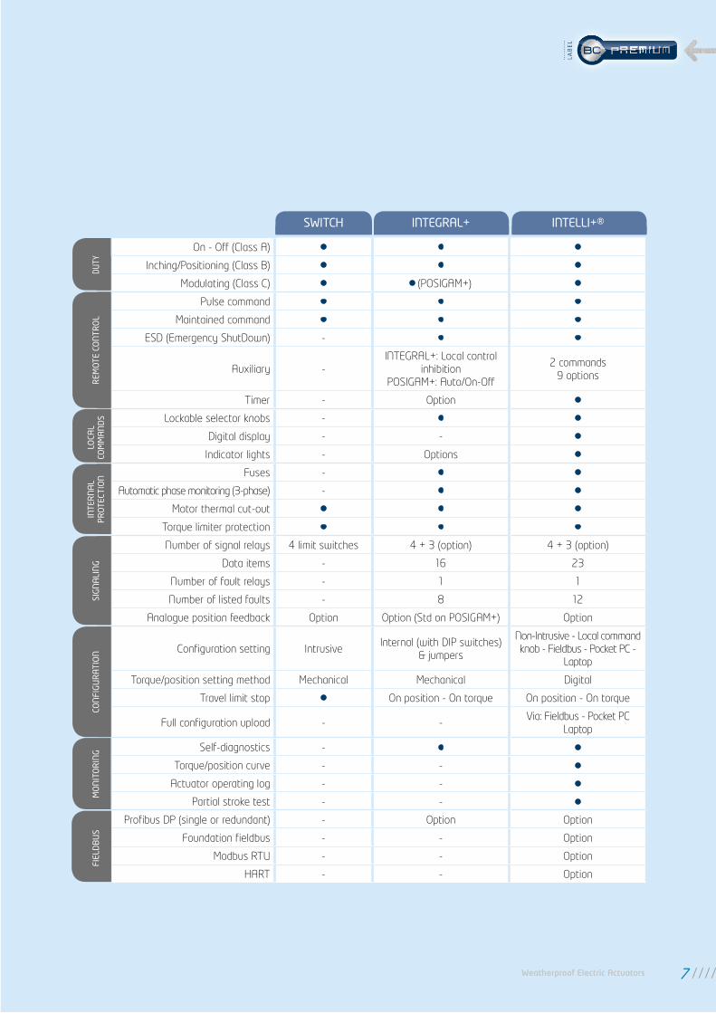
You can decide on local or remote control to meet the requirements of your particular system and the environment in which the actuators are to be used. BERNARD CONTROLS wide range of control systems enables you to choose the best solution for your needs.
Information Information
Integrated controls INTEGRAL+ / POSIGAM+
SWITCH controlThe customer provides the control logic to handle all the data received from the actuator electric contacts. The reversing starters are housed in the customer's own enclosure.
Integrated controlThe INTEGRAL+ control system is fully configurable and can perform all actuator control functions, including production of status reports, fault handling, protection systems and command processing. It offers local controls which can be disabled either locally or from a remote location. The reversing starters are incorporated in the control unit.
The POSIGAM+ control (Class III actuators) is based on the same electronics platform as the INTEGRAL+ but includes a positioner function. Proportional signals are used to control the actuator (setpoint) and to signal the valve actual position (feedback).
INTELLI+® controlThe INTELLI+® control allows the system to be set up and programmed without opening the unit. It includes an LCD screen plus tools for preventive maintenance. More information on INTELLI+® control on pages 14 to 17 and 33 to 35.
Wide Choice of Controls
66
SWITCH INTEGRAL+ INTELLI+®
DUTY
On - Off (Class A) • • •
Inching/Positioning (Class B) • • •
Modulating (Class C) • • (POSIGAM+) •
REM
OTE
CO
NTR
OL
Pulse command • • •
Maintained command • • •
ESD (Emergency ShutDown) - • •
Auxiliary -INTEGRAL+: Local control
inhibitionPOSIGAM+: Auto/On-Off
2 commands 9 options
Timer - Option •
LOCA
LCO
MM
AN
DS Lockable selector knobs - • •
Digital display - - •
Indicator lights - Options •
INTE
RN
AL
PRO
TECT
ION Fuses - • •
Automatic phase monitoring (3-phase) - • •
Motor thermal cut-out • • •
Torque limiter protection • • •
SIG
NA
LIN
G
Number of signal relays 4 limit switches 4 + 3 (option) 4 + 3 (option)
Data items - 16 23
Number of fault relays - 1 1
Number of listed faults - 8 12
Analogue position feedback Option Option (Std on POSIGAM+) Option
CON
FIG
UR
ATI
ON Configuration setting Intrusive
Internal (with DIP switches) & jumpers
Non-Intrusive - Local command knob - Fieldbus - Pocket PC -
Laptop
Torque/position setting method Mechanical Mechanical Digital
Travel limit stop • On position - On torque On position - On torque
Full configuration upload - -Via: Fieldbus - Pocket PC
Laptop
MO
NIT
OR
ING Self-diagnostics - • •
Torque/position curve - - •
Actuator operating log - - •
Partial stroke test - - •
FIEL
DB
US
Profibus DP (single or redundant) - Option Option
Foundation fieldbus - - Option
Modbus RTU - - Option
HART - - Option
Weatherproof Electric Actuators 7
LAB
EL
Heavy duty mechanical design
Reliability
• The gear design ensures lifetime lubrication by grease, thus reducing periodic maintenance requirements considerably.
Lubrication
• A built-in motor thermal switch protects the motor from overheating.
Motor thermal protection
• A visual position indicator allows a clear indication of the current valve position. In fact, this indicator is mechanically linked to the valve shaft.
Position indicator
• Gearing is self-locking at all speeds.
• Continuous gear drive between motor and valve.
• Unaffected by vibration on main mechanical parts
Trouble-free operation
• Asynchronous motor with high starting torque to unseat the valve.
• Excellent starting torque / nominal torque ratio.
• On/Off & Inching/Positioning operation: S4 motor with 30% duty rating for peak service conditions of up to 360 starts per hour.
• Modulating Class III: 50% duty rating for peak service conditions of up to 1,200 starts per hour.
• Motors easy to remove with sealed ball bearings fitted at front and rear.
Powerful motors
88
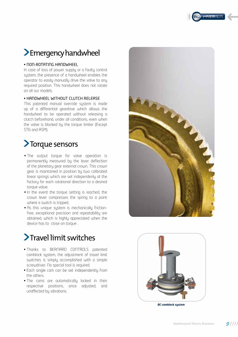
• The output torque for valve operation is permanently measured by the lever deflection of the planetary gear external crown. This crown gear is maintained in position by two calibrated linear springs which are set independenly at the factory for each rotational direction to a desired torque value.
• In the event the torque setting is reached, the crown lever compresses the spring to a point where a switch is tripped.
• As this unique system is mechanically friction-free, exceptional precision and repeatability are obtained, which is highly appreciated when the device has to close on torque .
Torque sensors
• Thanks to BERNARD CONTROLS patented camblock system, the adjustment of travel limit switches is simply accomplished with a simple screwdriver. No special tool is required.
• Each single cam can be set independently from the others.
• The cams are automatically locked in their respective positions, once adjusted, and unaffected by vibrations.
Travel limit switches
BC camblock system
• NON-ROTATING HANDWHEELIn case of loss of power supply or a faulty control system, the presence of a handwheel enables the operator to easily manually drive the valve to any required position. This handwheel does not rotate on all our models.
• HANDWHEEL WITHOUT CLUTCH RELEASE This patented manual override system is made up of a differential geardrive which allows the handwheel to be operated without releasing a clutch beforehand, under all conditions, even when the valve is blocked by the torque limiter (Except ST6 and ASM).
Emergency handwheel
Weatherproof Electric Actuators 9
LAB
EL

Reliability
The separated control box configuration can be specially useful when the actuator has to be mounted:
in a difficult access (manhole, in a high position,...) on a highly vibrating device in an excessively high or low temperature area
The maximum distance between control and actuator is 50 meters.
Separated control box (option)
Two barriers fitted with O-rings insure an optimum protection against water ingress into the electronic compartment.
This protection remains effective even if the cover has not been closed properly or if the cable glands have not been tightened.
Protection is also ensured for the local control selectors thanks to internal reed switches which prevent moisture ingress.
Double-sealing protector
O-rings
Cover
Cable entries
Captive screws
Double-sealing principle
Enclosure adapted to field constraintsFor ST & ASM with integrated and INTELLI+® controls, BERNARD CONTROLS offers reliable solutions adapted to field constraints.
1010
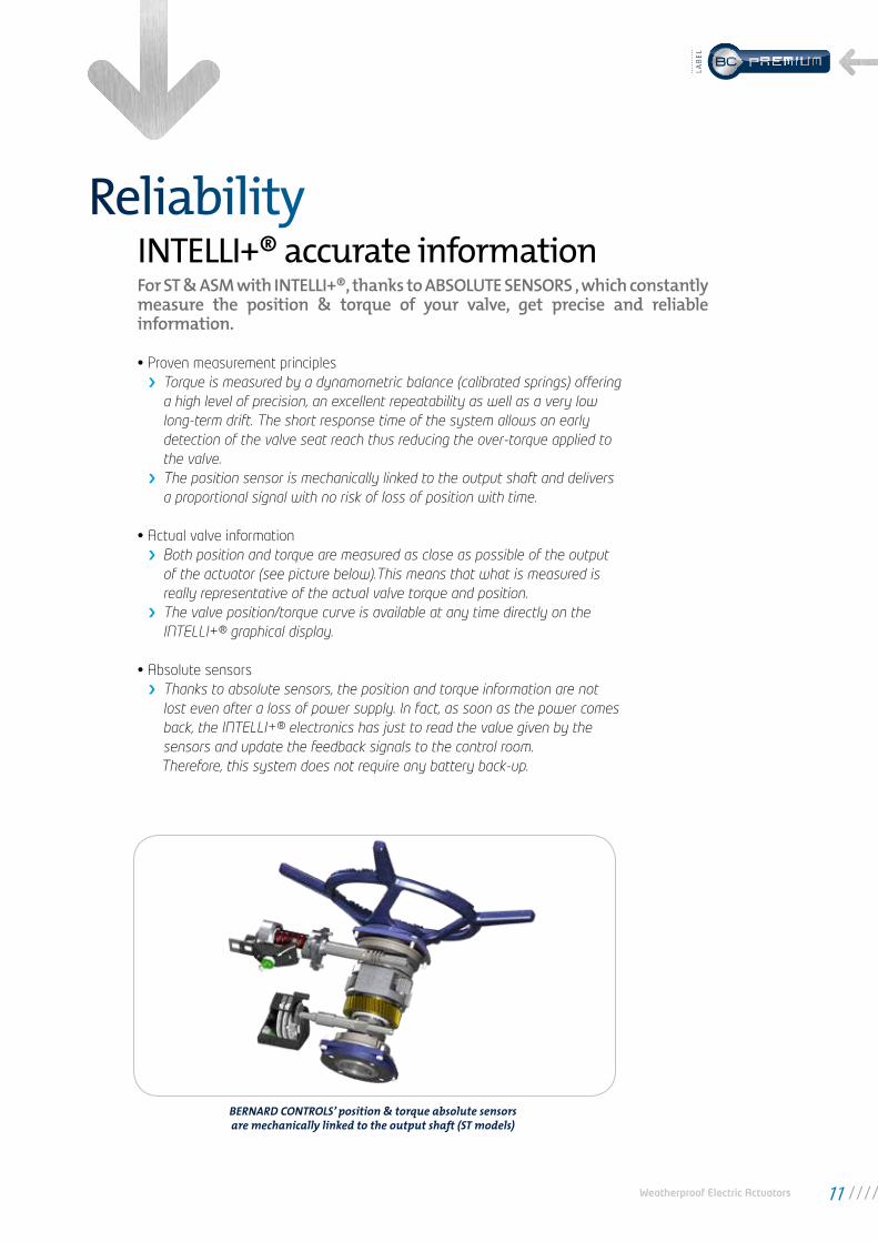
For ST & ASM with INTELLI+®, thanks to ABSOLUTE SENSORS , which constantly measure the position & torque of your valve, get precise and reliable information.
• Proven measurement principles Torque is measured by a dynamometric balance (calibrated springs) offering a high level of precision, an excellent repeatability as well as a very low long-term drift. The short response time of the system allows an early detection of the valve seat reach thus reducing the over-torque applied to the valve.
The position sensor is mechanically linked to the output shaft and delivers a proportional signal with no risk of loss of position with time.
• Actual valve information Both position and torque are measured as close as possible of the output of the actuator (see picture below).This means that what is measured is really representative of the actual valve torque and position.
The valve position/torque curve is available at any time directly on the INTELLI+® graphical display.
• Absolute sensors Thanks to absolute sensors, the position and torque information are not lost even after a loss of power supply. In fact, as soon as the power comes back, the INTELLI+® electronics has just to read the value given by the sensors and update the feedback signals to the control room.
Therefore, this system does not require any battery back-up.
BERNARD CONTROLS’ position & torque absolute sensors are mechanically linked to the output shaft (ST models)
INTELLI+® accurate informationReliability
Weatherproof Electric Actuators 11
LAB
EL

SecurityMotorised valve protection
BERNARD CONTROLS INTELLI+® controls offers key specifications for valve protection.
INTELLI+® includes an automatic phase correction device. In case of 3 phase power supply, whatever the power connection, the actuator always rotates in the correct direction.If one of the phases is not present, the actuator stops automatically and the fault relay drops.
An automatic delay protects the actuator and valve from all rapid rotational direction changes while limiting the effects of the mechanical pieces in inertia.
The actuator is totally autonomous and does not require a battery to operate. However, a signaling battery back-up optional board can be added for signaling purpose only.This battery is activated in case of loss of power supply and allows:
to use the INTELLI+® display. to update remote signalling (valve position, alarms, ...) to refresh fieldbus information
Low battery condition is automatically detected by the INTELLI+® and a warning message is sent. A low battery condition does not have any consequence on actuator operation.
Note: a 24VDC external power supply input is also present on the INTELLI+® board to achieve the same functionality and more.
One changeover (SPDT) relay indicates that the actuator is unavailable. This fault monitoring relay reports 5 types of defaults as a standard. Additional defaults to be reported can be easily added by the user (see Configuration on page 34). The monitoring relay is always energized and drops out only in event of a fault.
Phase monitoring
Protection of change in direction
Signaling continuity (option)
Fault monitoring relay
1212

Plant installations protection
ESD (Emergency Shut Down) is a remote emergency control signal with priority over all other commands. Depending upon the valve operation, ESD can be configured as an Open, Close or Stop command. To increase the availability of the actuator in extreme conditions, ESD can be set to ignore a torque overload condition.
Emergency shutdown (ESD)
This function enables an increase in the operating time of the actuator, i.e. to avoid water-hammer effect in a pipe. Travel time can be programmed independently in both opening and closing directions. It is also possible to apply the timer function to a limited section of the stroke.
Timer
Thanks to a fully dedicated control board and to an absolute position encoder with built-in self-test, BC INTELLI+® actuators are SIL 2 certified for the following safety integrated functions: Emergency Shut Down - Emergency Open - Emergency Stayput. These are also SIL3 capable for Emergency Shut Down and Emergency Open in 1oo2 configuration. Moreover, in case of emergency, the accuracy of signaling data is essential to make the good decision and activate the ESD functions. BERNARD CONTROLS offer SIL2 assessment on the following signaling functions: Valve open - Valve closed - 4/20mA analog position signal (optional function).
SIL Certification
INTELLI+® continuously monitors the actuator performances. Up to 17 different types of faults and alarms can be reported (refer to Configuration on page 28 for a complete list of alarms). An exclamation mark in a triangle on the local display indicates an alarm.The actuator can still operate normally in case of an alarm, for example there is an alarm after ‘Too many starts’. The alarm will automatically reset when the fault no longer exists.
Alarms indication
Partial stroking is a key specification of BERNARD CONTROLS actuators which enable to check the availability of the connected MOVs. This test consists in the execution of a very short return travel. Starting position as well as partial stroke amplitude are programmable.This command can be either hardwired or sent by fieldbus. A warning is generated in event of problems occuring during this test.
Partial Stroke Test (PST)
A password can be entered to protect access to parameters modification and actuator on valve setting.
Protection by password
Security
BERNARD CONTROLS INTELLI+® controls offers key specifications for installation protection.
Weatherproof Electric Actuators 13
LAB
EL

Display indications
INTELLI+® intuitive interface
Valve position in % of opening Valve torque can also be displayed in % of actuator maximum torque.
Local controls inhibited by the remote controller.
Emergency shutdown signal received.
Infrared link is detected.
Bluetooth link is detected.
This icon is displayed in case of alarm.
When a positioner is built-in, the set point value is displayed in percentage.This indication is blinking in case of loss of control signal.
This icon indicates that the fieldbus board is installed. The square displays the status of the communication: no communication, communication in progress or faulty module.
In case of redundant fieldbus interface, two squares are displayed. The squares display the status of each communication line:no communication, a channel is acting as primary or backup, communicationin progress or a faulty module.
ESD
0%
BUS
1 2
ESD
0%
BUS
1 2
ESD
0%
BUS
1 2
5% OpenTorque 20%
ESD
0%
BUS
1 2
ESD
0%
BUS
1 2
ESD
0%
BUS
1 2
ESD
0%
BUS
1 2
User-friendly controls
• Menu guided settings using clear messages. Language can be freely selected among: Chinese, English, French, German, Italian, Polish, Portuguese, Russian and Spanish
• The LCD display gives a clear status of the actuator and of the control system:
Position in percentage (for example 5% Open) When the valve is fully closed, closed is displayed When the valve is fully open, open is displayed
Actual torque expressed as % of actuator maximum torque Alarm/fault flag
Graphical display
1414

• INTELLI+® user interface is intuitive.• INTELLI+® operation does not rely on a battery.• No tool is needed to have access to the menu in any case.
• 2 LEDs (red/green) indicate the position (close/open) at ends of travel, and direction of running (blinking).• Red and green LED can be freely assigned to open or closed positions.
• The red selector enables the operator to choose remote control, local control function and stop during operation. It can also inhibit all use of the actuator (OFF position). This selector switch can be locked in each position (padlock not supplied).
• The blue selector allows local operation of the actuator in either direction: OPEN or CLOSE.• Local commands can be inhibited remotely.
Autonomous
Local signaling
Local commands
LANGUAGE: to change the language of the display (9 languages available)
CHECK: to read all the actuator parameters and configuration (activity, alarms, commands, torque, data sheet, position, positioner, signaling, timer, fieldbus)
SET UP: to set up the actuator on the valve (closing mode, close direction, position setting)
CHANGE: to modify the actuator configuration (activity, commands, torque, data sheet, position, positioner, signaling, timer, fieldbus)
EXIT SETUP: to exit the actuator setup
User-friendly menu
Selector to validate the choice (ok)Selector to navigate up and down into the menu
OK
Weatherproof Electric Actuators 15
LAB
EL

INTELLI+® non intrusive settings
During the actuator on valve setting procedure, the user is guided step by step by INTELLI+®: Choice of closing (on torque or on position), Choice of direction to close, Drive the actuator to the closed and the open position and validate the position.
For certain valves, as an example gate valves equipped with back seat, INTELLI+® can automatically perform this setting: the actuator detects the extreme posi-tions (using the torque limiter), tests the inertia in order to optimize this setting.
Manual or automatic setting
As an alternative, BERNARD CONTROLS proposes the Bluetooth technology which uses radio signals to communicate between the PC with INTELLISOFT and the INTELLI+® controls.• Accessibility: the user does not need to position himself in front of the actuator
and can move its computer without loss of communication.• Simplicity and security: the PC/PDA automatically detects all devices located
at a maximum distance of 10m. Each actuator holds a unique identifier and the connection can be protected with a password.
Bluetooth communication (option)
If necessary, operating parameters can be modified with the local control buttons by following information on the display.
Parameters modification
INTELLI+® offers the possibility to communicate with a standard laptop through an infra-red link with INTELLIKIT or INTELLIPOCKET.• INTELLIPOCKET is a real industrial pocket PC
which eases the engineer’s job on site both for setting up and throughout product lifetime.
• INTELLIKIT is a communication kit neces-sary to communicate with INTELLI+®, made of the INTELLISOFT communication software developed by BERNARD CONTROLS and an infrared transmitter receiver connected to USB. All functions (use, settings / configuration, status, etc…) are available through the computer.
Infrared communication
Screen with INTELLISOFT
Thanks to INTELLI+®, commissioning is simplified and can be performed in a non-intrusive way. Upon user’s request the actuator parameters can be preset at the factory. In this case, start-up simply consists in setting the actuator on the valve.
User-friendly controls
1616
User-friendly controls
Thanks to its absolute sensors and its microprocessor technology, INTELLI+® continuously monitors its components as well as the actuator status and measures some important valve parameters. INTELLI+® provides users with a great deal of information to help with system diagnosis and aid in scheduling their valves preventative maintenance. INTELLI+® helps maximise process availability by reducing maintenance downtime.
INTELLI+® preventative maintenance
Parameters are available on the display through the menu to check the activity of the actuator:
Number of starts: total starts since the actuator manufacturing. A partial counter can be selected. Running time: total running time since the actuator manufacturing. Starts last 12h: number of starts in the last 12 hours (to check the modulating activity i.e.).
Handwheel action: indicates if the handwheel was operated by manual operation since the last electrical command.
INTELLI+® stores in its memory the data sheet of the actuator: customer tag number, BERNARD CONTROLS serial number, duty rating, classification level, manufacturing date, etc.
INTELLI+® checks the operation of its components, particularly torque sensor, position sensor, microprocessor and EEPROM memory.INTELLI+® constantly monitors its performance in order to detect any problem of over-travel, jammed motor, rotation direction, lost phase, motor thermal overload and many others.Refer to Configuration page 28 for the complete list of alarms.
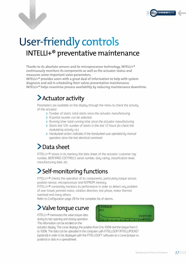
INTELLI+® memorizes the valve torque data during its last opening and closing operation. This information can be recalled on the actuator display. The curve displays the position from 0 to 100% and the torque from 0 to 100%. The data can be uploaded in the computer with INTELLISOFT/INTELLIPOCKET (optional) in order to be displayed with the INTELLISOFT software as a curve (torque vs. position) or data in a spreadsheet.
Actuator activity
Data sheet
Self-monitoring functions
Valve torque curve
Weatherproof Electric Actuators 17
LAB
EL

INTELLI+® can be equipped with an analogue position & torque feedback board. This module delivers a 0/4-20mA signal proportional to the percentage of the valve opening. A voltage signal (i.e. 0-10V) can also be obtained by connecting an external resistance. The board can be either supplied by an external (12 to 32 VDC) source of power or internally, by the INTELLI+® electronics. This module also delivers a 4 - 20mA signal propotional to the real torque of the valve.
A positioner board can be installed into the INTELLI+® to allow the operator todrive the valve to intermediate positions (Inching/Positioning & Modulating duties).The positioner module has been designed to work with either current(i.e. 4-20mA) or voltage (i.e. 0-10V) analogue signals
One input signal: the set-point One output signal: the actual valve position feedback
The input and output signals are fully isolated from each other.The setting procedure is fully automatic and is performed in a non-intrusive way. The dead band can be adjusted by the user.
Remote indication is done through 4 relays, with the possibility of 23 available information.Voltage free relays maintain their positions without battery backup. Normally open or normally closed contact can be chosen. An optional board with 3 single option relays allows reporting of 3 additional indications.
Remote control can be achieved using a 10 to 250 V external voltage supplyor by dry contacts, which uses the actuators internal 24 VDC voltage supply.This control can be configured as a pulse or self-holding remote command.Inputs on the board are completely isolated by opto-isolators.It is also possible to control the actuator with a unique external contact, using one of the two functions Priority to open or Priority to close .
Position & torque transmitter
Positioner
Remote indications
Wire by wire command
Hardwired controlsFOCUS ON
18
Weatherproof Electric Actuators 19

BERNARD CONTROLS actuators can be connected to most of the standard fieldbuses available on the market:
• PROFIBUS DP• FOUNDATION FIELDBUS• MODBUS RTU• HART• Other fieldbus on demand.
For more security, redundant fieldbus ensures continuous operation, even in case of a bus line disruption. Indeed, all elements of the bus line (bus controller, lines, actuators interfaces) are doubled.
Open versus Proprietary systems:
Two physical concepts of fieldbus are available from various providers.
• The Proprietary so-called system: This is a technology designed by a device manufacturer for his own needs. A Proprietary system always includes the actuators with the specific bus interface, but also the bus controller located at the line head-end. Only the products proposed by the bus controller manufacturer can be installed on the bus.
• Open systems: One using standard international fieldbuses so various manufacturers can supply compatible controllers and interfaces. This type of technology is proven, reliable and offers fast response time.
BERNARD CONTROLS chooses the open system for all its fieldbus solutions.
POINT-TO-POINT CONNECTIONEACH ACTUATOR HAS TO BE CONNECTED TO THE CONTROL CABINET
MULTIDROP CONNECTIONMANY UNITS CONNECTED ON A SINGLE PAIR OF WIRES;ALL COMMANDS AND SIGNALS CAN BE TRANSMITTED BY THE BUS
Valve 1
Valve 2
Valve 3
Valve 1
Valve 2
Valve 3
VALVE OPENVALVE CLOSEDOPEN THE VALVECLOSE THE VALVE...
VALVE OPENVALVE CLOSEDOPEN THE VALVECLOSE THE VALVE...
VALVE OPENVALVE CLOSEDOPEN THE VALVECLOSE THE VALVE...
Valve 1
Valve 2
Valve 3
VALVE OPENVALVE CLOSEDOPEN THE VALVECLOSE THE VALVE...
Fieldbus communicationwith INTELLI+® control
The fieldbus, present on a large number of installations,is used more and more to communicate information and commands with multiple actuators and deviceswired in series on a single pair of wires. Thus, the number of information available from each actuator can be multiplied while reducing the overall cost of wiring on the site.
FOCUS ON
20

• Based on robust PLC technology and open fieldbus protocol
• Up to 120 actuators and 10km distance
• Fast response time. Standard scan time 1 to 3 s whatever the distance and number of actuators connected
• 1 to 3 lines starts
• Simple or redundant configurations
• Overall start up time reduced to the minimum
BERNARD CONTROLS Master Station
Weatherproof Electric Actuators 21
LAB
EL

Product specifications ST SWITCH & INTEGRAL+/POSIGAM+ specifications
GEN
ERA
L
DescriptionST actuators SWITCH version include motor with thermal protection, gear case, emergency handwheel, connection box, travel limit switches, torque switches and output drive. Wide range of number of turns: 2 to 1080 turns
Torque range ST6 = 60 Nm ST30 = 300 Nm ST14 = 140 Nm ST70 = 700 Nm ST175 = 1750 Nm ST220 = 2200Nm
Type of service
Adapted to process requirements: • On-Off : Class A actuators complying with EN15714-2 and improved endurance Class A+ actuators • Inching/Positioning: Class B actuators complying with EN15714-2 and improved endurance Class B+
actuators• Modulating: Class III actuators with higher duty performance and specification of additional
performance criteria compared to EN15714-2 Class C basic design requirements
ENCL
OSU
RE
- PR
OTE
CTIO
N
Casing• Aluminium die casting • Iron cast casing for ST175/ST220 • Cover fastened by captive and stainless screws
External Protection
• Type : polyurethane coating in standard Protection: - Standard: C3 according to ISO 12944 - Option : highly corrosive conditions: C5M • Color: RAL 5002 Blue Other possibilites on request
Weatherproof • IP68 - 5m /72h
Ambient temperaturerange ATEX and IEC Ex
• Standard : -20 ... +70°C / -4 ... +158°F• Low temp. option : -40 ... +70°C / -40 ... +158°F• High temp. option : +0 ... +90°C / +32 ... +194°F (available only on SWITCH versions)
Vibration resistance 1g (9.8 m/s²) at 10-500 Hz. (Contact our sales teams for higher vibration levels).
MO
TOR
Motor technology • TENV design (Totally-enclosed, not ventilated) 3-phase or single-phase asynchronous motor,
class F insulation with integral thermal overload protection.• TENV DC motors with 2-wire connection available for some references
Motor duty rating
• On/Off operation (complying with EN15714-2 Class A) and Inching/Positioning (complying with EN15714-2 Class B): S4-30% motor duty rating. Up to 360 starts per hour at peak of operation.
• BC Modulating Class III (complying with EN15714- 2 Class C) : S4-50% motor duty rating. Up to 1 200 starts per hour at peak of operation.
MEC
HA
NIC
AL
SPEC
IFIC
ATI
ON
Gear design • Reduction by largely sized worm & wheel gear type • The gears are mechanically self-locking
Manual emergency operation
Handwheel which does not rotate during motor operation. • Automatic switch between manual and electrical operation without clutch release lever (exept
ST6). Priority to electric drive.• Manual control gear ratios: ST6:1:1, ST14/30:1/2, ST70:1/21, ST175/220: 1/31 • Maximum rim force to apply conform to EN 12570
Output flange Actuator flanges comply with ISO 5210.
Lubrication The actuators are lubricated for the product lifetime and do not require any special maintenance.
ELEC
TRIC
AL
SPEC
IFIC
ATI
ON
Power supply
Actuators can operate on a wide variety of power supplies: • single-phase or 3-phase, DC, • up to 690 V (depending on version), • 50 or 60 Hz
Terminal compartment
• SWITCH : All control elements are directly connected to screw type terminals, size 4 mm² for controls and power supply, according to enclosed wiring diagram.
• INTEGRAL+ : Ring tongue terminals inside control box • Internal and external earth ground rod.
Fuse protection INTEGRAL+
INTEGRAL+ : 3 fuses : FU1 : transformer primary fuse 6,3 x 32mm - 0,5A - 500V; FU2 : transformer secondary fuse 5 x 20mm - 0,5A; FU3 : transformer tertiary fuse 5 x 20mm - 0,05A
Conduit entries
SWITCH : • 2 x M20 • 2 x M20 + 1 x M25 (as an option)INTEGRAL+ : • 3 x M20 • 2 x M20 + 2 x M25 (as an option) orWith INTEGRALBUS option• 3 x M20 + 2 x M16 (or 4xM16 for bus redundant)ST175/ST220:• 2 x 1’’ + 1 x 1’’1/2 • + 2 x 3/4’’ for fieldbus (as an option) • (or 4x 3/4’’ for bus redundant)
22
POSI
TIO
N &
TO
RQ
UE
SEN
SOR
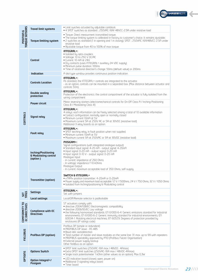
STravel limit systems • Limit swiches actuated by adjutable camblock.
• 4 SPDT switches as standard ; 250VAC-16A/ 48VCC-2.5A under resistive load
Torque limiting system
• Torque: Direct measurment transmitted torque.• The torque limiting system is calibrated in factory to customer’s choice. It remains ajustable.• 2 switches as standard (1 in opening and 1 in closing); SPDT ; 250VAC-16A/48VCC-2.5A under
resistive load• Ajustable torque from 40 to 100% of max torque
CON
TRO
LS
Control
INTEGRAL+: • Isolated by opto-couplers• Voltage: 10 to 250 V DC/AC• Current: 10 mA at 24V• Dry contacts (uses INTEGRAL+ auxillary 24 VDC supply)• Minimum pulse duration: 100ms• Time of rotational direction’s change: 50ms (default value) or 200ms
Indication A dial type window provides continuous position indication.
Controls Location
INTEGRAL+: As standard, the INTEGRAL+ controls are integrated to the actuator. - as an option, controls can be mounted in a separated box. (Max distance between actuator and controls 50m).
Double sealing protection
INTEGRAL+: Protection of the electronics: the control compartment of the actuator is fully isolated from the wiring compartment
Power circuit Motor reversing starters (electromechanical controls for On-Off Class A / Inching-Positioning Class B / Modulating Class III)
Signal relay
INTEGRAL+: 4 relays: each information can be freely selected among a total of 10 available information• Contact configuration: normally open or normally closed• Minimum current 10mA at 5V• Maximum current 5A at 250V AC or 5A at 30VDC (resistive load)Additional 3 relay boards as an option.
Fault relay
INTEGRAL+: • SPDT latching relay, in fault position when not supplied.• Minimum current 10mA at 5V• Maximum current 5A at 250VAC or 5A at 30VDC (resistive load)
Inching/Positioning & Modulating control (option )
POSIGAM+: Signal configurations (with integrated analogue output): • Standard input signal: 4-20 mA - output signal: 4-20mA • Input signal: 0-20 mA - output signal: 0-20 mA • Input signal: 0-10 V - output signal: 0-20 mA Analogue Input: - in current: impedance of 260 Ohms - In voltage: impedance f 10 kOhms Analogue Output: - In current: maximum acceptable load of 350 Ohms, self-supply
Transmitter (option)
SWITCH & INTEGRAL+ • «TAM» position transmitter: 4-20mA or 0-20mA• Power supply and maximum load acceptable: 12 V / 150Ohms, 24 V / 750 Ohms, 32 V / 1050 Ohms• Isolated from Inching/positioning & Modulating control
SET
TIN
GS Settings INTEGRAL+:
Set with jumpers
Local settings Local/Off/Remote selector is padlockable
COM
FOR
MIT
Y T
O
EC D
IREC
TIV
ES
Compliance with EC Directives
ST actuators comply with: • directive 2004/108/EC Electromagnetic compatibility • directive 2006/95/EC Low voltage • the following harmonised standards: EN 61000-6-4: Generic emissions standard for industrial
environments; EN 61000-6-2: Generic immunity standard for industrial environments; EN 60034-1: Rotating electrical machines; EN 60529: Degrees of protection provided by enclosures (IP ratings code)
FIEL
DB
US
Profibus DP (option)
Profibus DP (simple or redundant)• PROFIBUS-DP slave - RS 485• Baud rate: autodetection• Total number of master and slave modules on the same line: 31 max. up to 99 with repeaters• PROFIBUS operability approved by PNO (Profibus Nutzer Organisation)• External power supply backupOther fieldbus as an option
OP
TIO
NS Options Switch
• DPDT limit switches (250VAC-16A max / 48VDC- 4Amax)• Extra DPDT limit switches (250VAC-16A max / 48VDC-4Amax)• Single track potentiometer 1 kOhm (other values as an option). Max 0,3W
Option Integral+/Posigam
• LED indication board (closed, open, power on) • Additional 3 signaling relays board • Timer board
Weatherproof Electric Actuators 23
LAB
EL

ST INTELLI+® specifications
GEN
ERA
L
DescriptionST actuators offer a wide range of torques. INTELLI+® control offers many advanced solutions. An INTELLI+® controls with SIL2/SIL3 assessment is also available (see dedicated catalog for detailled specifications). Wide range of number of turns: 2 to 900 turns
Torque rangeST6 = 60 Nm / ST30 = 300 Nm / ST14 = 140 Nm / ST70 = 700 Nm / ST175 = 1750 Nm / ST220 = 2200Nm
Type of service
Adapted to process requirements: • On-Off : Class A actuators complying with EN15714-2 and improved endurance Class A+ actuators• Inching/Positioning: Class B actuators complying with EN15714-2 and improved endurance Class B+
actuators• Modulating: Class III actuators with higher duty performance and specification of additional
performance criteria compared to EN15714-2 Class C basic design requirements
ENCL
OSU
RE
- PR
OTE
CTIO
N
Casing• Aluminium die casting • Iron cast casing for ST175/ST220 • Cover fastened by captive and stainless screws
External Protection
• Type : polyurethane coating Protection:- Standard: C3 according to ISO 12944- Option : highly corrosive conditions: C5M• Color: RAL 5002 BlueOther possibilites on request
Weatherproof • IP68 - 5m / 72h
Ambient temperaturerange ATEX and IEC Ex
• Standard : -20 ... +70°C / -4 ... +158°F• Low temp. option : -40 ... +70°C / -40 ... +158°F
Vibration resistance 1g (9.8 m/s²) at 10-500 Hz. (2g for INTELLI+® with SIL)(Contact our sales teams for higher vibration levels).
MO
TOR
Motor technology • TENV design (Totally-enclosed, not ventilated) 3-phase or single-phase asynchronous motor,
class F insulation with integral thermal overload protection.• TENV DC motors with 2-wire connection available for some references
Motor duty rating
• On/Off operation (complying with EN15714-2 Class A) and Inching/Positioning (complying with EN15714-2 Class B): S4-30% motor duty rating. Up to 360 starts per hour at peak of operation.
• BC Modulating Class III (complying with EN15714- 2 Class C) : S4-50% motor duty rating. Up to 1 200 starts per hour at peak of operation.
MEC
HA
NIC
AL
SPEC
IFIC
ATI
ON
Gear design• Reduction by largely sized worm & wheel gear type • The gears are mechanically self-locking
Manual emergency operation
Handwheel which does not rotate during motor operation. • Automatic switch between manual and electrical operation without clutch release lever (exept
ST6). Priority to electric drive.• Manual control gear ratios: ST6:1:1, ST14/30:1/2, ST70:1/21, ST175/220: 1/31 • Maximum rim force to apply conform to EN 12570
Output flange Actuator flanges comply with ISO 5210.
Lubrication The actuators are lubricated for the product lifetime and do not require any special maintenance.
ELEC
TRIC
AL
SPEC
IFIC
ATI
ON Power supply
Actuators can operate on a wide variety of power supplies: • single-phase or 3-phase, DC, • up to 690 V (depending on version), • 50 or 60 Hz
Terminal compartment • Ring tongue terminals • Internal and external ground rod
Fuse protectionPrimary fuse (6.3 x 32mm - 0.5 A) located on the transformer board. 2 automatic fuses for low internal voltages.
Conduit entries
• Cable glands supplied as an option • 3xM20 in standard • + 2xM16 for fieldbus (as an option) • (or 4xM16 for bus redundant)
24

PO
SITI
ON
&
TOR
QU
E SE
NSO
RS
Travel limit systems• Position: movement reading on output shaft. • Position sensor : Absolute encoder
Torque limiting system • Torque: Direct measurment transmitted torque.• The torque limiting system is calibrated in factory to customer’s choice. It remains ajustable via
INTELLI+® (non intrusive setting)
CON
TRO
LS
Control
Command by: • voltage: 10 to 250 V DC/AC (current 10 mA at 24V) • dry contact (use INTELLI+® auxiliary 24 VDC supply) Command Signal Isolated by opto-couplers Minimum command pulse duration: 100ms Time of rotational direction change: 200ms (factory setting range 50 to 500 ms)
Visual position indication
A LCD screen dial type window provides continuous position indication even in the event of power supply loss using 24VDC back-up supply or optionnal battery.
Controls LocationAs standard, the INTELLI+® control is integrated to the actuator. On option, controls can be mounted in a separated box (max distance between actuator and controls 50m).
Double sealing protection
Protection of the electronics: the control compartment of the actuator is fully isolated from the wiring compartment
Power circuitMotor reversing starters (electromechanical controls for On-Off Class A / Inching-Positioning Class B / Modulating Class III)
Auxiliary power supply 24VDC in standard. 48VDC as an option.
Signal relay
4 relays: each information can be freely selected among a total of 23 available information • Contact configuration: normally open or normally closed • Minimum current 10mA at 5V • Maximum current 5A at 250V AC or 5A at 30VDC (resistive load) Additional 3 relay boards as an option.
Default relay• SPDT monostable relay, in fault position when not supplied. • Minimum current 10mA at 5V • Maximum current 5A at 250V AC or 5A at 30V DC (inductive load)
Inching/Positioning & Modulating control (option)
Input (setpoint) and output (feedback) signals are fully isolated from each other Signal configurations (selectable): • Input signal: 4-20 mA - output signal : 4-20mA • Input signal: 0-20 mA - output signal : 0-20mA • Input signal: 0-10 V - output signal : 0-20mA (0-10V with an external resistance) Analogue inputs • in current: impedance of 160 Ohms • in voltage: impedance of 11 KOhms Analogue outputs: • in current: maximum acceptable load of 750 Ohms at 24 VDC supply • In voltage: minimum acceptable load of 50 KOhms (with a shunt resistance of 500 Ohms)
Transmitter (option)
Proportional position (0/4-20 mA) and torque (4-20 mA) feedback board Analogue outputs: • in current: maximum acceptable load of 750 Ohms at 24 VDC supply • In voltage: minimum acceptable load of 50 KOhms (with a shunt resistance of 500 Ohms)
Signaling continuity (option)
Allows to use the display and update the open and closed position information (through the signaling relays or via fieldbus or via Transmitter option) in case of lack of power supply
SETT
ING
S
SettingsNon-Intrusive. All actuator settings and parameters are stored in a non-volatile EEPROM memory. Protection by password. Adjustable via Local control; Infrared link or Bluetooth (as an option; to keep an high level of security, Bluetooth range is limited to 10m).
Local settingsThe INTELLI+® can be fully set via its local display and selectors. Does not require any specific setting tool. Local / Off / Remote selector is padloackable
INTELLIKIT (option)• INTELLISOFT CD-ROM for laptop PC. • Infrared module to connect to the laptop (USB) and clip on the actuator window • USB cable (2 meters length max.)
INTELLI POCKET (option)
• Protection: IP65 (option: ATEX II2G EEx ia IICT4) • Shock resistance: 1.2 m on concrete • Communication: with INTELLI+®: infrared link (40 cm maximum distance) or bluetooth (up to
10m) / with PC: bluetooth, IRDA, Wifi (802.11b) as a standard• Optional USB station • Operating system : Windows Mobile 2005 • 64Mb RAM + 256Mb storage card
Weatherproof Electric Actuators 25
LAB
EL

COM
FOR
MIT
Y T
O
EC D
IREC
TIV
ES
Compliance with EC Directives
ST actuators comply with: • directive 2004/108/EC Electromagnetic compatibility • directive 2006/95/EC Low voltage • the following harmonised standards: EN 61000-6-4: Generic emissions standard for industrial
environments; EN 61000-6-2: Generic immunity standard for industrial environments; EN 60034-1: Rotating electrical machines; EN 60529: Degrees of protection provided by enclosures (IP ratings code)
FIEL
DB
US
Profibus DPV1 (option)
• PROFIBUS-DPV1 - RS 485• Baud rate: 9.6 kbit/s up to 1.5 Mbit/s (autodetection)• Communication protocol: PROFIBUS DPV1 slave-cyclic & acyclic• Type of connection: single line (standard) or redundant line (option)• Cable specification: Profibus certified cable only• Line connection without repeater - Actuators per line: 31 max. - Line length: 1.2 km max. (0.75 mi)• Line connection with repeaters - Number of repeaters per line: 9 max - 30 actuators and 1 Km max. per segment . - Number of actuators per line with repeater: 124 maximum - Line length with 9 repeaters: 10.2 km max. (6.2 mi)• Scan speed (30 units & 1.2 km): 0.1s (at a baud rate of 93.75 Kbit/s)• Power supply: internal and isolated via INTELLI+®. 24VCC emergency power supply to refresh Open/Close position information in case of loss of electric supply• Technical approval: operability approved by PNO (Profibus Nutzer Organisation)
Modbus (option)
• MODBUS RTU - RS 485 • Transmission medium: 1 shielded pair cable • Functions: Half Duplex, asynchronous mode, multidrop • Baud rate: 1.2k to 115 Kbit/s • Format: 8 data bits, 1 stop bit, no parity • Communication protocol: Modbus (slave) • Modbus address: configurable by the actuator menu
Foundation Fieldbus (option)
• H1 speed = 31.25kBit/s • Fully compliant with fieldbus standard IEC 61158 • Physical layer: IEC 61158-2, 2 wires communication • Current consumption: 20mA • Operating voltage: 9 to 32 VDC • Cable specification: Type A (for example: 3076F Belden) • Line connection - Actuators per line without repeater: 31 max. - Line length without repeater: 1.9 km max. (1.2 mi) - Number of repeaters per line: 4 max. - Maximum number of actuators and line length depends on consumption available • Technical approval: Foundation tested. Several DCS manufacturer operability checked.
HART (option)
• Interface: HART, 4-20mA current, FSK modulation • Transfer speed: 1.2 kbit/s • Protocol: HART 7.4 • Impedance: 250 Ohms • Power consumption: Internal by Intelli+ transformer, External power supply for 4-20mA loop only • Actuator configuration: Available through EDD file • Connection line: Point-to-Point or Multi-drop • Technical approval: approved by Hart Communication Foundation
OP
TIO
N
Option INTELLI+®
• Heating resistance (6W max) • Position feed-back (current loop) • Torque feed-back (current loop) • Fieldbus interface • Signaling continuity • 3 additionnal signaling relays
ST INTELLI+® specifications
26

ASM SWITCH & INTEGRAL+/POSIGAM+ specificationsG
ENER
AL
DescriptionThe ASM range is mainly designed to work in combination with gearboxes. Wide range of number of turns: 2 to 270 turns
Torque range ASM-6: 60Nm, ASM10: 100Nm, ASM16: 160Nm, ASM20: 200Nm
Type of service
Adapted to process requirements: • On-Off : Class A actuators complying with EN15714-2 and improved endurance Class A+ actuators• Inching/Positioning: Class B actuators complying with EN15714-2 and improved endurance Class B+
actuators• Modulating: Class III actuators with higher duty performance and specification of additional
performance criteria compared to EN15714-2 Class C basic design requirements
ENCL
OSU
RE
- PR
OTE
CTIO
N
Casing • Aluminium die casting • Cover fastened by captive and stainless screws
External Protection
• Type : polyurethane coating Protection:- Standard: C3 according to ISO 12944- Option : highly corrosive conditions: C5M• Color: RAL 5002 BlueOther possibilites on request
Weatherproof • IP67 in standard • IP68 (5m/72h) as an option
Ambient temperaturerange ATEX and IEC Ex
• Standard : -20 ... +70°C / -4 ... +158°F• Low temp. option : -40 ... +70°C / -40 ... +158°F• High temp. option : +0 ... +90°C / +32 ... +194°F (available only on SWITCH versions)
Vibration resistance 1g (9.8 m/s²) at 10-500 Hz. (Contact our sales teams for higher vibration levels).
MO
TOR
Motor technology • TENV design (Totally-enclosed, not ventilated) 3-phase or single-phase asynchronous motor,
class F insulation with integral thermal overload protection.• TENV DC motors with 2-wire connection available for some references
Motor duty rating
• On/Off operation (complying with EN15714-2 Class A) and Inching/Positioning (complying with EN15714-2 Class B): S4-30% motor duty rating. Up to 360 starts per hour at peak of operation.
• BC Modulating Class III (complying with EN15714- 2 Class C) : S4-50% motor duty rating. Up to 1 200 starts per hour at peak of operation.
MEC
HA
NIC
AL
SPEC
IFIC
ATI
ON
Gear design
• Two reduction stages : - Planetary system with high speed reduction and excellent efficiency - Worm & wheel gear type • One additionnal planetary system on ASM16/ASM20 • The gears are mechanically self-locking when associated with worm and wheel gearboxes. • Self-locking system as an option for other mechanical devices.
Manual emergency operation
Actuators are fitted with a handwheel for manual emergency operation. Declutch system with motor priority • Manual control gear ratios: ASM6-ASM10: 1:1, ASM16-ASM20 : 1:3 • Force to apply conform to EN 12570 standard
Output flange Actuator flanges comply with ISO 5210. ASM16/20 available only in B3 or B4 form.
Lubrication The actuators are lubricated for the product lifetime and do not require any special maintenance.
ELEC
TRIC
AL
SPEC
IFIC
ATI
ON
Power supply
Actuators can operate on a wide variety of power supplies: • single-phase or 3-phase, DC, • up to 690 V (depending on version), • 50 or 60 Hz
Terminal compartment
• SWITCH : All control elements are directly connected to screw type terminals according to enclosed wiring diagram.
• INTEGRAL+ : Ring tongue terminals inside control box • Internal and external earth ground rod.
Fuse protection
INTEGRAL+ : 3 fuses : FU1 : transformer primary fuse 6,3 x 32mm - 0,5A - 500V FU2 : transformer secondary fuse 5 x 20mm - 0,5A FU3 : transformer tertiary fuse 5 x 20mm - 0,05A
Entrées de câbles Conduit entries
SWITCH : • 2 x M20• 2 x M20 + 1 x M25 (as an option)INTEGRAL+ : • 3 x M20 • 2 x M20 + 2 x M25 (as an option) orWith INTEGRALBUS option• 3 x M20 + 2 x M16 (or 4xM16 for bus redundant)
Weatherproof Electric Actuators 27
LAB
EL
PO
SITI
ON
& T
OR
QU
E SE
NSO
RS
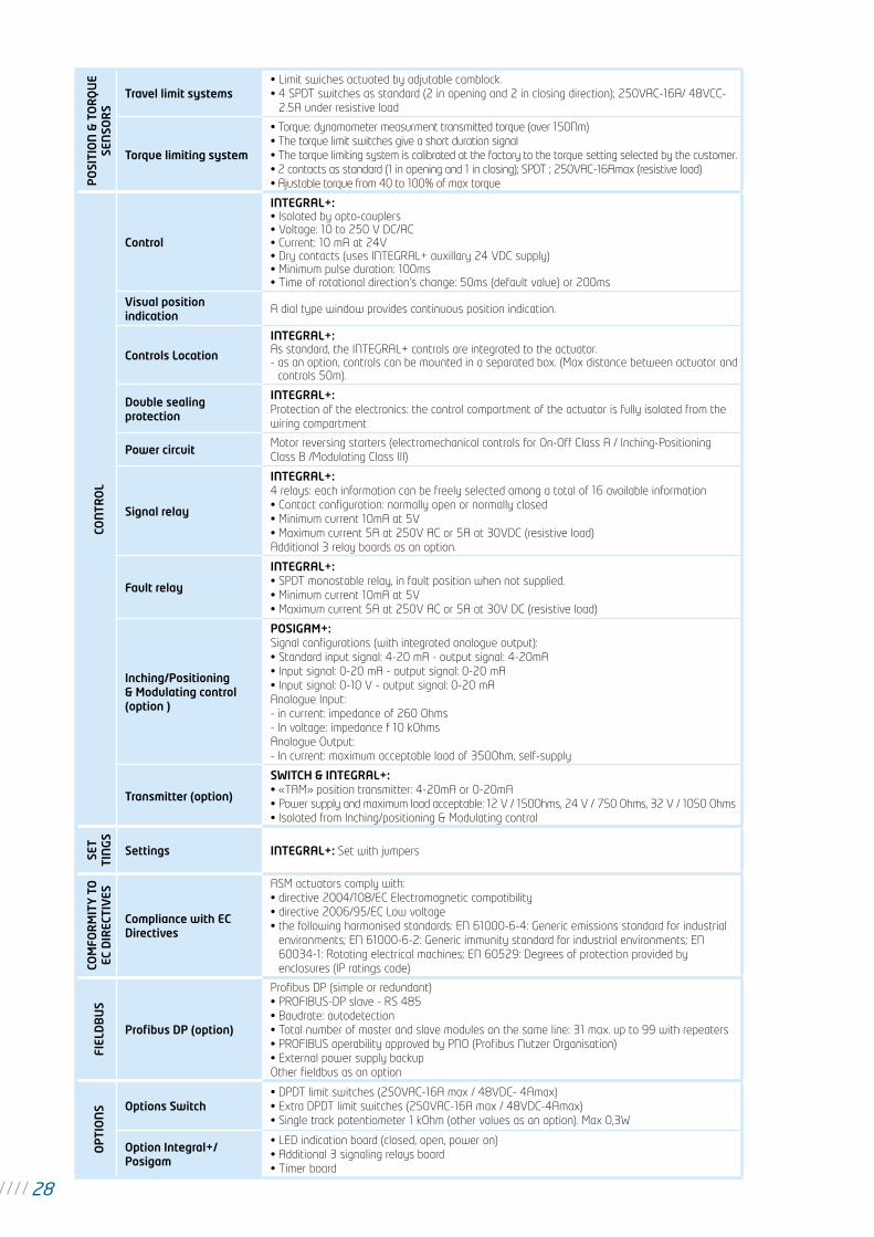
Travel limit systems• Limit swiches actuated by adjutable camblock. • 4 SPDT switches as standard (2 in opening and 2 in closing direction); 250VAC-16A/ 48VCC-
2.5A under resistive load
Torque limiting system
• Torque: dynamometer measurment transmitted torque (over 150Nm)• The torque limit switches give a short duration signal• The torque limiting system is calibrated at the factory to the torque setting selected by the customer.• 2 contacts as standard (1 in opening and 1 in closing); SPDT ; 250VAC-16Amax (resistive load)• Ajustable torque from 40 to 100% of max torque
CON
TRO
L
Control
INTEGRAL+: • Isolated by opto-couplers• Voltage: 10 to 250 V DC/AC• Current: 10 mA at 24V• Dry contacts (uses INTEGRAL+ auxillary 24 VDC supply)• Minimum pulse duration: 100ms• Time of rotational direction’s change: 50ms (default value) or 200ms
Visual position indication
A dial type window provides continuous position indication.
Controls Location
INTEGRAL+: As standard, the INTEGRAL+ controls are integrated to the actuator. - as an option, controls can be mounted in a separated box. (Max distance between actuator and
controls 50m).
Double sealing protection
INTEGRAL+: Protection of the electronics: the control compartment of the actuator is fully isolated from the wiring compartment
Power circuitMotor reversing starters (electromechanical controls for On-Off Class A / Inching-Positioning Class B /Modulating Class III)
Signal relay
INTEGRAL+: 4 relays: each information can be freely selected among a total of 16 available information • Contact configuration: normally open or normally closed • Minimum current 10mA at 5V • Maximum current 5A at 250V AC or 5A at 30VDC (resistive load) Additional 3 relay boards as an option.
Fault relay
INTEGRAL+: • SPDT monostable relay, in fault position when not supplied.• Minimum current 10mA at 5V • Maximum current 5A at 250V AC or 5A at 30V DC (resistive load)
Inching/Positioning & Modulating control (option )
POSIGAM+: Signal configurations (with integrated analogue output): • Standard input signal: 4-20 mA - output signal: 4-20mA • Input signal: 0-20 mA - output signal: 0-20 mA • Input signal: 0-10 V - output signal: 0-20 mA Analogue Input: - in current: impedance of 260 Ohms - In voltage: impedance f 10 kOhms Analogue Output: - In current: maximum acceptable load of 350Ohm, self-supply
Transmitter (option)
SWITCH & INTEGRAL+: • «TAM» position transmitter: 4-20mA or 0-20mA• Power supply and maximum load acceptable: 12 V / 150Ohms, 24 V / 750 Ohms, 32 V / 1050 Ohms• Isolated from Inching/positioning & Modulating control
SET
TIN
GS
Settings INTEGRAL+: Set with jumpers
COM
FOR
MIT
Y T
O
EC D
IREC
TIV
ES
Compliance with EC Directives
ASM actuators comply with: • directive 2004/108/EC Electromagnetic compatibility • directive 2006/95/EC Low voltage • the following harmonised standards: EN 61000-6-4: Generic emissions standard for industrial
environments; EN 61000-6-2: Generic immunity standard for industrial environments; EN 60034-1: Rotating electrical machines; EN 60529: Degrees of protection provided by enclosures (IP ratings code)
FIEL
DB
US
Profibus DP (option)
Profibus DP (simple or redundant) • PROFIBUS-DP slave - RS 485 • Baudrate: autodetection • Total number of master and slave modules on the same line: 31 max. up to 99 with repeaters • PROFIBUS operability approved by PNO (Profibus Nutzer Organisation) • External power supply backup Other fieldbus as an option
OP
TIO
NS Options Switch
• DPDT limit switches (250VAC-16A max / 48VDC- 4Amax)• Extra DPDT limit switches (250VAC-16A max / 48VDC-4Amax)• Single track potentiometer 1 kOhm (other values as an option). Max 0,3W
Option Integral+/Posigam
• LED indication board (closed, open, power on) • Additional 3 signaling relays board • Timer board
28
ASM INTELLI+® specificationsG
ener
al
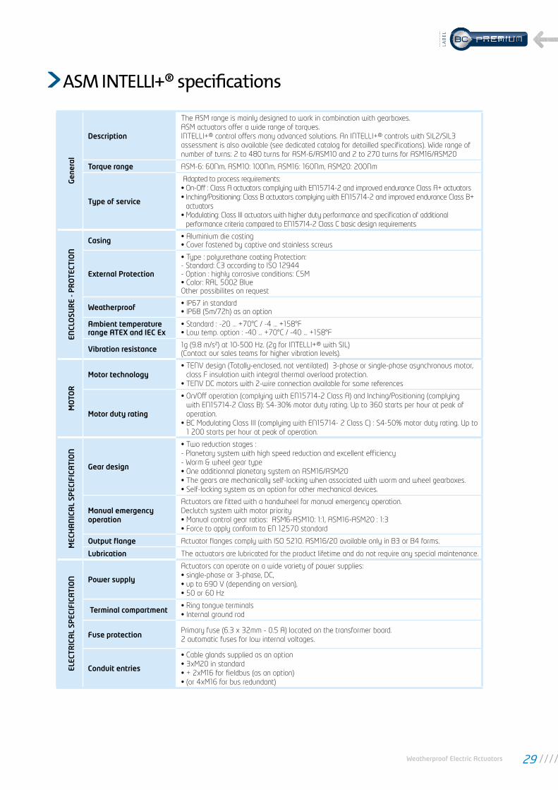
Description
The ASM range is mainly designed to work in combination with gearboxes. ASM actuators offer a wide range of torques. INTELLI+® control offers many advanced solutions. An INTELLI+® controls with SIL2/SIL3 assessment is also available (see dedicated catalog for detailled specifications). Wide range of number of turns: 2 to 480 turns for ASM-6/ASM10 and 2 to 270 turns for ASM16/ASM20
Torque range ASM-6: 60Nm, ASM10: 100Nm, ASM16: 160Nm, ASM20: 200Nm
Type of service
Adapted to process requirements: • On-Off : Class A actuators complying with EN15714-2 and improved endurance Class A+ actuators• Inching/Positioning: Class B actuators complying with EN15714-2 and improved endurance Class B+
actuators• Modulating: Class III actuators with higher duty performance and specification of additional
performance criteria compared to EN15714-2 Class C basic design requirements
ENCL
OSU
RE
- PR
OTE
CTIO
N
Casing • Aluminium die casting • Cover fastened by captive and stainless screws
External Protection
• Type : polyurethane coating Protection:- Standard: C3 according to ISO 12944- Option : highly corrosive conditions: C5M• Color: RAL 5002 BlueOther possibilites on request
Weatherproof • IP67 in standard • IP68 (5m/72h) as an option
Ambient temperaturerange ATEX and IEC Ex
• Standard : -20 ... +70°C / -4 ... +158°F• Low temp. option : -40 ... +70°C / -40 ... +158°F
Vibration resistance 1g (9.8 m/s²) at 10-500 Hz. (2g for INTELLI+® with SIL)(Contact our sales teams for higher vibration levels).
MO
TOR
Motor technology • TENV design (Totally-enclosed, not ventilated) 3-phase or single-phase asynchronous motor,
class F insulation with integral thermal overload protection.• TENV DC motors with 2-wire connection available for some references
Motor duty rating
• On/Off operation (complying with EN15714-2 Class A) and Inching/Positioning (complying with EN15714-2 Class B): S4-30% motor duty rating. Up to 360 starts per hour at peak of operation.
• BC Modulating Class III (complying with EN15714- 2 Class C) : S4-50% motor duty rating. Up to 1 200 starts per hour at peak of operation.
MEC
HA
NIC
AL
SPEC
IFIC
ATI
ON
Gear design
• Two reduction stages : - Planetary system with high speed reduction and excellent efficiency - Worm & wheel gear type • One additionnal planetary system on ASM16/ASM20 • The gears are mechanically self-locking when associated with worm and wheel gearboxes. • Self-locking system as an option for other mechanical devices.
Manual emergency operation
Actuators are fitted with a handwheel for manual emergency operation. Declutch system with motor priority • Manual control gear ratios: ASM6-ASM10: 1:1, ASM16-ASM20 : 1:3 • Force to apply conform to EN 12570 standard
Output flange Actuator flanges comply with ISO 5210. ASM16/20 available only in B3 or B4 forms.
Lubrication The actuators are lubricated for the product lifetime and do not require any special maintenance.
ELEC
TRIC
AL
SPEC
IFIC
ATI
ON Power supply
Actuators can operate on a wide variety of power supplies: • single-phase or 3-phase, DC, • up to 690 V (depending on version), • 50 or 60 Hz
Terminal compartment • Ring tongue terminals • Internal ground rod
Fuse protectionPrimary fuse (6.3 x 32mm - 0.5 A) located on the transformer board. 2 automatic fuses for low internal voltages.
Conduit entries
• Cable glands supplied as an option • 3xM20 in standard • + 2xM16 for fieldbus (as an option) • (or 4xM16 for bus redundant)
Weatherproof Electric Actuators 29
LAB
EL

PO
SITI
ON
&
TOR
QU
E SE
NSO
R
Travel limit systems• Position: movement reading on output shaft. • Position sensor : Absolute encoder
Torque limiting system • Torque: dynamometer measuring transmitted torque .• The torque limiting system is calibrated in factory to customer’s choice. It remains ajustable via
INTELLI+® (non intrusive setting)
CON
TRO
L
Control
Command by: • voltage: 10 to 250 V DC/AC (current 10 mA at 24V) • dry contact (use INTELLI+® auxiliary 24 VDC supply) Command Signal Isolated by opto-couplers Minimum command pulse duration: 100ms Time of rotational direction change: 200ms (factory setting range 50 to 500 ms)
Visual position indication
A LCD screen dial type window provides continuous position indication even in the event of power supply loss using 24VDC back-up supply or optionnal battery.
Controls LocationAs standard, the INTELLI+® control is integrated to the actuator. As an option, controls can be mounted in a separated box (max distance between actuator and controls 50m).
Double sealing protection
Protection of the electronics: the control compartment of the actuator is fully isolated from the wiring compartment
Power circuitMotor reversing starters (electromechanical controls for On-Off Class A / Inching-Positioning Class B / Modulating Class C)
Auxiliary power supply 24VDC in standard. 48VDC as an option.
Signal relay
4 relays: each information can be freely selected among a total of 23 available information • Contact configuration: normally open or normally closed • Minimum current 10mA at 5V • Maximum current 5A at 250V AC or 5A at 30VDC (resistive load) Additional 3 relay boards as an option.
Default relay• SPDT monostable relay, in fault position when not supplied.• Minimum current 10mA at 5V • Maximum current 5A at 250V AC or 5A at 30V DC (inductive load)
Inching/Positioning & Modulating control (option)
Input (setpoint) and output (feedback) signals are fully isolated from each other Signal configurations (selectable): • Input signal: 4-20 mA - output signal : 4-20mA • Input signal: 0-20 mA - output signal : 0-20mA • Input signal: 0-10 V - output signal : 0-20mA (0-10V with an external resistance) Analogue inputs • in current: impedance of 160 Ohms • in voltage: impedance of 11 KOhms Analogue outputs: • in current: maximum acceptable load of 750 Ohms at 24 VDC supply • In voltage: minimum acceptable load of 50 KOhms (with a shunt resistance of 500 Ohms)
Transmitter (option)
Proportional position (0/4-20 mA) and torque (4-20 mA) feedback board Analogue outputs: • in current: maximum acceptable load of 750 Ohms at 24 VDC supply • In voltage: minimum acceptable load of 50 KOhms (with a shunt resistance of 500 Ohms)
Signaling continuity (option)
Allows to use the display and update the open and closed position information (through the signaling relays or via fieldbus or via Transmitter option) in case of lack of power supply
SETT
ING
S
Settings
Non-Intrusive. All actuator settings and parameters are stored in a non-volatile EEPROM memory. Protection by password.Adjustable via Local control; Infrared link or Bluetooth (as an option; to keep an high level of security, Bluetooth range is limited to 10m).
Local settingsThe INTELLI+® can be fully set via its local display and selectors Does not require any specific setting tool Local / Remote selector is padloackable
INTELLIKIT (option)• INTELLISOFT CD-ROM for laptop PC. • Infrared module to connect to the laptop (USB) and clip on the actuator window • USB cable (2
meters length max.)
INTELLI POCKET (option)
• Protection: IP65 (option: ATEX II2G EEx ia IICT4) • Shock resistance: 1.2 m on concrete • Communication: with INTELLI+®: infrared link (40 cm maximum distance) or bluetooth (up to
10m) / with PC: bluetooth, IRDA, Wifi (802.11b) as a standard• Optional USB station • Operating system : Windows Mobile 2005 • 64Mb RAM + 256Mb storage card
ASM INTELLI+® specifications
30

COM
FOR
MIT
Y T
O
EC D
IREC
TIV
ES
Compliance with EC Directives
ASM actuators comply with: • directive 2004/108/EC Electromagnetic compatibility • directive 2006/95/EC Low voltage • the following harmonised standards: EN 61000-6-4: Generic emissions standard for industrial
environments; EN 61000-6-2: Generic immunity standard for industrial environments; EN 60034-1: Rotating electrical machines; EN 60529: Degrees of protection provided by enclosures (IP ratings code)
FIEL
DB
US
Profibus DPV1 (option)
• PROFIBUS-DPV1 - RS 485• Baud rate: 9.6 kbit/s up to 1.5 Mbit/s (autodetection)• Communication protocol: PROFIBUS DPV1 slave-cyclic & acyclic• Type of connection: single line (standard) or redundant line (option)• Cable specification: Profibus certified cable only• Line connection without repeater - Actuators per line: 31 max. - Line length: 1.2 km max. (0.75 mi)• Line connection with repeaters - Number of repeaters per line: 9 max - 30 actuators and 1 Km max. per segment . - Number of actuators per line with repeater: 124 maximum - Line length with 9 repeaters: 10.2 km max. (6.2 mi)• Scan speed (30 units & 1.2 km): 0.1s (at a baud rate of 93.75 Kbit/s)• Power supply: internal and isolated via INTELLI+®. 24VCC emergency power supply to refresh Open/Close position information in case of loss of electric supply• Technical approval: operability approved by PNO (Profibus Nutzer Organisation)
Modbus (option)
• MODBUS RTU - RS 485 • Transmission medium: 1 shielded pair cable • Functions: Half Duplex, asynchronous mode, multidrop • Baud rate: 1.2k to 115 Kbit/s • Format: 8 data bits, 1 stop bit, no parity • Communication protocol: Modbus (slave) • Modbus address: configurable by the actuator menu
Foundation Fieldbus (option)
• H1 speed = 31.25kBit/s • Fully compliant with fieldbus standard IEC 61158 • Physical layer: IEC 61158-2, 2 wires communication • Current consumption: 20mA • Operating voltage: 9 to 32 VDC • Cable specification: Type A (for example: 3076F Belden) • Line connection - Actuators per line without repeater: 31 max. - Line length without repeater: 1.9 km max. (1.2 mi) - Number of repeaters per line: 4 max. - Maximum number of actuators and line length depends on consumption available • Technical approval: Foundation tested. Several DCS manufacturer operability checked.
HART (option)
• Interface: HART, 4-20mA current, FSK modulation • Transfer speed: 1.2 kbit/s • Protocol: HART 7.4 • Impedance: 250 Ohms • Power consumption: Internal by Intelli+ transformer, External power supply for 4-20mA loop only • Actuator configuration: Available through EDD file • Connection line: Point-to-Point or Multi-drop • Technical approval: approved by Hart Communication Foundation
OP
TIO
NS
Option INTELLI+®
• Heating resistance (6W max) • Position feed-back (current loop) • Torque feed-back (current loop) • Fieldbus interface • Signaling continuity • 3 additionnal signaling relays
Weatherproof Electric Actuators 31
LAB
EL

specificationsMounting flange
FlangeMax. stem diameter (mm)
Type A (max) Type B1 (max) Type B3 Type C (max)
ST6 F10 30 42 20 32
ST14 F10 38 42 20 40
ST30 F14 42 60 30 45
ST70 F16 54 80 40 56
ST175 F25 85 100 50 90
ST220 F30 90 120 60 90
ASM6 F10 30 42 20 32
ASM10 F10 30 42 20 32
ASM16 F14 N/A N/A 30 N/A
ASM20 F14 N/A N/A 30 N/A
ISO 5210 requirements
Flange Max torqueMax. thrust
with stem nutMounting bolts
F10 100 N.m 40 000 N 4 x M10 / d=102 mm
F14 400 N.m 100 000 N 4 x M16 / d=140 mm
F16 700 N.m 150 000 N 4 x M20 / d=165 mm
F25 1200 N.m 200 000 N 8 x M16 / d=254 mm
F30 2500 N.m 325 000 N 8 x M20 / d=298 mm
Type ASTEM NUT
Type B1LARGE DIA.
Type B3SMALL DIA.
Type CCLAW COUPLING
Thrust accepted Thrust not accepted Thrust not accepted Thrust not accepted
32
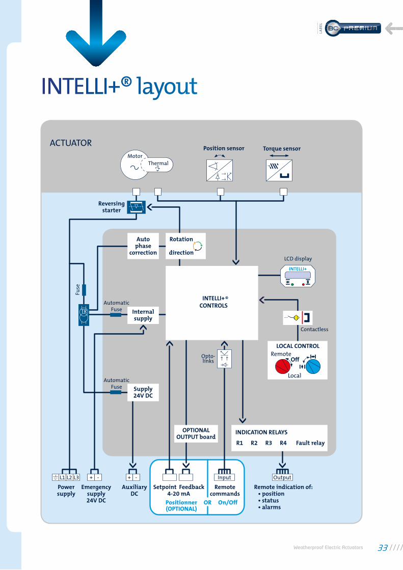
INTELLI+® layout
Position sensor
Reversingstarter
Autophase
correction
Internalsupply
Supply24V DC
OPTIONALOUTPUT board
LOCAL CONTROLRemote
Local
INDICATION RELAYS
R1 R2 R3 R4 Fault relay
Off
Rotation
direction
INTELLI+CONTROLS
Torque sensor
LCD display
INTELLI+
Motor
ACTUATOR
Thermal
Fuse
TR
AutomaticFuse
AutomaticFuse
Opto-links
Contactless
Powersupply
Emergencysupply24V DC
AuxiliaryDC
Remotecommands
Remote indication of: • position • status • alarms
Input+L1 L2 L3 - + -
Setpoint
Positionner OR On/Off(OPTIONAL)
Feedback4-20 mA
Output
®
Weatherproof Electric Actuators 33
LAB
EL

INFORMATION STANDARD CONFIGURABLE
• Tag number (8 digits)• Actuator serial number (unchangeable)• Manufacturing date (unchangeable)• Password (000) • Password (3 digits)
Close directionClosing modeSetting of torque limit system Closing torque Opening torque settingOnly if closing the valve on torque Valve seat torque Torque to unseat the valve
• Clockwise• On position
• 100%• 100%
• 100%• 100%
• Counter-clockwise• On torque
• Other values between 40 and 100%• Other values between 40 and 100%
• Other values between 40 and 100%• Other values between 40 and 100%
or without any limitation
Auxiliary remote commands(2 chosen from 10)
Fault tolerance degradation (ESD)
Auxiliary command activated by a contact
• Local command inhibit but local stop available (auxiliary command 1)
• ln emergency closing (ESD) (auxiliary command 2)
• None
• Normally open
• Local plus remote control or remote control only
• Local or remote control • Local command inhibited • Open/Close inhibited• Auto / modulating / On-Off• Emergency closing (ESD)• Emergency opening (ESD)• Emergency stopping (ESD)• Partial stroke• No thermal overload (weatherproof
versions only)• Full torque (100%)
• Normally closed
Blue selector operating mode
Stop local, while remote command
• By pulse (a pulse is enough to achieve an opening or closing command)
• Authorized
• Maintained (actuator operates while the operator holds the button)
• Increments from 0 to 100% (actuator moves the valve to the position set in % of opening)
• Inhibited
• None • Open priority• Close priority• Open and close priority
Faults reported on fault relay • Control circuit power lost (always included)
• Fuse blown (always included)• Thermal cutoff has tripped (always
included)• Lost phase (always included)• Locked rotor (always included)• Local / remote selector set to local• Local / remote selector set to off
• Jammed valve• Actuator receives an emergency
command (ESD)• The actuator receives an inhibit
command• Overtravel• 4 - 20 mA signal lost (if positioner
option installed)
OPE
NIN
G/
CLO
SIN
G
PRIO
RIT
YLO
CAL
COM
MA
ND
SCO
MM
AN
DS
SET
UP
DA
TASH
EET
FAU
LT R
ELA
Y
INTELLI+® offers a lot of information, many of them can be configurable by the user as it is shown in the following table.
INTELLI+® Configuration
34

* Voltage signal with an external resistance
INFORMATION STANDARD CONFIGURABLE
Information reported on signaling relays
Each contact can be:
• Valve open (for R1 and R3)• Valve closed (for R2 and R4)
• Normally open (when something occurs, contact is closed)
• Torque limiter action in the opening / closed direction
• Valve in intermediate position, between x% and y% of opening (for example: 10% to 50%)
• Selector in local/remote/off• The actuator is moving (fixed signal)• The actuator is moving (blinking signal)• Moving in the open/close direction
(fixed signal)• Moving in the open/close direction
(blinking signal)• Emergency command (ESD)• Stop mid-travel• The actuator is normally powered• The motor thermal cutoff has tripped• Jammed valve• In three-phase, a phase is missing• 4-20 mA signal lost (if positioner
option installed)• The handwheel has been activated
since the last electrical movement• If fieldbus option is installed, this relay
is assigned to an external command• Battery low (if installed)• Partial stroking in progress / in fault• Normally closed
In case of communication loss • Remain in position • Go to closed position • Go to open position
Position remote indication
Torque remote indication
Signal variation direction
• 4-20mA
• 4-20mA
• Signal increases in the open direction
• 0-20mA and 0-10V*• 4-12 mA• 12-20 mA
• Signal decreases in the open direction
Auxiliary command 1
Type of signal
Signal direction
Dead band setting
In case of 4-20mA signal loss
• Switch: automatic control (proportional command) / On-Off (standard Open /Close command)
• 4-20mA
• Signal increases in the open direction
• 1%
• Remain in position
• 0-20mA and 0-10V• 4-12mA• 12-20mA
• Signal decreases in the open direction
• Other value between 0.2 and 5%
• Go to fully closed position• Go to fully open position
SIG
NA
LLIN
G R
ELA
YSFI
ELD
BU
S (o
ptio
n)
AN
ALO
G P
OSI
TIO
NFE
EDB
ACK
BO
AR
D (o
ptio
n)
AN
ALO
GU
E CO
NTR
OL:
PO
SITI
ON
ER
(opt
ion)
Weatherproof Electric Actuators 35
LAB
EL

Invest in Confidence
CAT
02
-08
_EN
G_G
RP
_rev
01c
B E R N A R D C O N T R O L S G R O U PCORPORATE HEADQUARTERS4 rue d’Arsonval - CS 70091 / 95505 Gonesse CEDEX France / Tel. : +33 (0)1 34 07 71 00 / Fax : +33 (0)1 34 07 71 01 / [email protected]
CONTACT BY OPERATING AREAS
>AMERICAS
NORTH AMERICABERNARD CONTROLS UNITED STATES [email protected]. +1 281 578 66 66
SOUTH AMERICABERNARD CONTROLS LATIN [email protected]. +1 281 578 66 66
>ASIA
CHINABERNARD CONTROLS CHINA &BERNARD CONTROLS CHINA [email protected]. +86 (0) 10 6789 2861
KOREABERNARD CONTROLS [email protected]. +82 2 553 6957
SINGAPOREBERNARD CONTROLS [email protected]. +65 65 654 227
>EUROPE
BELGIUMBERNARD CONTROLS BENELUXNIVELLES (BRUSSELS)[email protected]@bernardcontrols.comTel. +32 (0)2 343 41 22
FRANCEBERNARD CONTROLS FRANCE &BERNARD CONTROLS NUCLEAR FRANCEGONESSE (PARIS)[email protected]. +33 (0)1 34 07 71 00
GERMANYBERNARD CONTROLS DEUFRATROISDORF (KÖLN)[email protected]. +49 2241 9834 0
ITALYBERNARD CONTROLS ITALIARHO (MILANO)[email protected]. +39 02 931 85 233
RUSSIABERNARD CONTROLS [email protected]. +33 (0)1 34 07 71 00
SPAINBERNARD CONTROLS [email protected]. +34 91 30 41 139
UNITED KINGDOMBERNARD CONTROLS UNITED [email protected]. +44 (0)7435 266310
>INDIA, MIDDLE EAST & AFRICA
AFRICABERNARD CONTROLS AFRICAABIDJAN - IVORY [email protected]. + 225 21 34 07 82
INDIABERNARD CONTROLS [email protected]. +971 4 880 0660
MIDDLE-EASTBERNARD CONTROLS MIDDLE-EASTDUBAI - [email protected]. +971 4 880 0660
All
data
in t
his
bro
chu
re a
re g
iven
for
info
rmat
ion
on
ly a
nd
are
subj
ect
to c
han
ge w
ith
out
not
ice.
More than 50 agents and distributors worldwide. Contact details on www.bernardcontrols.com