electric infrared process heating: state-of-the-art assessment
TRANSCRIPT

EPRl Electric Power Research lnst itute
Topics: Infrared heating Radiant heating Electrotec hnology End use Technology assessment Technology utilization
EPRl EM-4571 Project 2478-1 Final Report March 1987
m 3 2@& JJd
Po F
Electric Infrared Process Heating: S tate-of4 he-Art Assessment
Prepared by Battelle Columbus Division Columbus, Ohio

R E P O R T S U M M A R Y ~~ ~
SUBJECT Industrial electric technologies
TOPICS Infrared heating End use Radiant heating Technology assessment Electrotechnology Technology utilization
Customer service engineers / Marketing managers AUDIENCE
Electric Infrared Process Heating: State-of-the-Art Assessment Electric infrared heating-heating by electromagnetic radiation- can provide U.S. industries with reliable process control, more- efficient energy use, and improved productivity. This study found, however, that the technology is not as widely used as it might deserve. EPRl R&D is now focusing on expanding the range of industrial applications.
BAC KG RO U N D Electric infrared (IR) heating equipment generates and directs IR elec- tromagnetic radiation onto a product to heat its surface. Such radiant heat- ing is suitable for industrial applications where direct contact heating (conduction) is impossible or undesirable. This assessment of the technol- ogy is part of an EPRl effort to promote the efficient use of electricity in energy-intensive industries.
OBJECTIVE
APPROACH
RES U LTS
To assess the state of the art of electric IR heating in the United States, France, the United Kingdom, the Federal Republic of Germany, Sweden, and Japan.
After an extensive review of the technical literature, the project team inter- viewed several electric IR furnace and oven manufacturers on the industrial uses of the technology both within and outside the United States. They then compiled information on the state of new developments, R&D needs, markets, applications, and major trends in the industry.
The major findings of the assessment are as follows:
Estimates of the total U.S. market range from $40 million to $50 million per year. The fact that the smaller, more mature European market is esti- mated to be $70-$80 million per year suggests that infrared heating tech- nology is greatly underused in the United States and that the market has the potential for significant growth.
Radiant heating is used principally to heat thin materials-such as foil or steel strapping-and to cure and dry surface films such as paints, inks, coatings, and adhesives. Often perceived as a niche technology, radiant heating is actually adaptable to a variety of uses. It has the potential to dis- place many existing gas convection heating applications.
EPRl EM-4571s

In the past, misapplications and poor engineering-in part the result of underestimating the technology’s sophistication-have hindered widespread acceptance of electric IR. Increased use for industrial pro- cess heating is likely to occur when documented demonstrations and case histories of successful applications convince the user that the risk is negligible.
As a mature and well-known electrotechnology, IR heating offers the utility industry an opportunity to promote a highly efficient use of elec- tricity in near-term applications. Utilities and governments in other countries have recognized the value of IR heating and have developed promotional programs to increase its use. In the United States, in- creased automation, the need for reliable process control, and the need for more-efficient energy use are leading to new applications for this process. Along with electrotechnologies such as resistance heating, laser processing, and induction heating (EPRI reports EM-4130, EM-3465, and EM-4131, respectively), IR heating demonstrates the unique characteristics electricity offers for improving industrial productivity.
EPRl PERSPECTIVE
PROJECT RP2478-1 EPRl Project Manager: I. Leslie Harry Energy Management and Utilization Division Contractor: Battelle Columbus Division
For further information on EPRl research programs, call EPRl Technical Information Specialists (415) 855-2411.
Electric Infrared Process Heating: State-of-the-Art Assessment
E M -4571 Research Project 2478-1
Final Report, March 1987
Prepared by
BATTELLE COLUMBUS DIVISION 505 King Avenue
Columbus, Ohio 43201-2693
Principal Investigator J. R . Bush
Prepared for
Electric Power Research Institute 3412 Hillview Avenue
Palo Alto, California 94304
EPRl Project Manager I. L. Harry
Industrial Program Energy Management and Utilization Division

OR DER I N G I N FOR MATI 0 N
Requests for copies of this report should be directed to Research Reports Center (RRC), Box 50490, Palo Alto, CA 94303, (415) 965-4081. There is no charge for reports requested by EPRl member utilities and affiliates, US. utility associations, US. government agencies (federal, state, and local), media, and foreign organizations with which EPRl has an information exchange agreement. On request, RRC will send a catalog of EPRl reports.
Electric Power Research Institute and EPRl are registered service marks of Electric Power Research Institute, Inc
Copyright 0 1987 Electric Power Research Institute, Inc. All rights reserved
NOTICE This report was prepared by the organization($ named below as an account of work sponsored by the Electric Power Research Institute, Inc. (EPRI). Neither EPRI, members of EPRI, the organization(s) named below, nor any person acting on behalf of any of them: (a) makes any warranty, express or implied, with respect to the use of any information, apparatus, method, or process disclosed in this report or that such use may not infringe privately owned rights; or (b) assumes any liabilities with respect to the use of, or for damages resulting from the use of, any information, apparatus, method, or process disclosed in this report.
Prepared by Battelle Columbus Division Columbus, Ohio

ABSTRACT
Electric infrared ( I R ) process heating employs electrical resistance to heat an emitting material specifically for the purpose of generating thermal (infrared) radiation. actually adaptable to a variety of applications. electrotechnology which lacks a nationally prominent advocate to sponsor and promote its efficient use. Electric I R heating unit sales are currently growing at a 10 to 12 percent per year rate and the U.S. market exists for potentially greater rate increases.
While often perceived as a "niche" technology, electric I R heating is Electric I R heating is a mature
i i i

i

ACKNOWLEDGMENTS
This report is one of a series of electrotechnology assessments prepared at Battelle Columbus Division in cooperation with the EPRI Center for Metals Fabrication. Mr. Thomas G. Byrer, Director of the Center of Metals Fabrication. Special thanks is given to Mr. John Harvey o f Epner Technology Inc. whose interest and support contributed significantly to this project.
The overall project has been conducted under the supervision of
His assistance was greatly appreciated.
V

i
i
CONTENTS
Sect ion
1 INTRODUCTION Methods o f Heat Transfer Electromagnetic Radiat ion I n f r a r e d Radiat ion
Page
2 PRINCIPAL CONCEPTS OF INFRARED HEATING Radiat ion Frequency and Wavelength D i s t r i b u t i o n o f I R Radiat ion I n f r a r e d Sources
Gas-Fired I n f r a r e d Sources E l e c t r i c I n f r a r e d Emi t ters
E f f i c i e n c y Heating E f f i c i e n c y Radiant E f f i c i e n c y
3 HEATING PROCESS COMPARISON AND ADVANTAGES OF ELECTRIC INFRARED HEATING
Competing Processes Advantages o f I n f r a r e d Radiat ion i n I n d u s t r i a l Appl icat ions Comparison o f Gas vs. E l e c t r i c I n f r a r e d
Advantages o f E l e c t r i c I n f r a r e d Other Advantages o f E l e c t r i c IR Heating
4 APPLICATIONS AND ECONOMIC FACTORS P r i n c i p a l App l ica t ion Areas Typica l Appl icat ions I d e n t i f y i n g and Developing Appl icat ions Economic Factors
Cost o f Equipment Fuel /Overal l Energy Costs
1-1 1-1 1-2 1-3
2-1 2-1 2-1 2-3 2-4 2-4 2-8 2-8 2-9
3-1
3-1 3-3 3-4 3-4 3-5
4-1 4-1 4-3 4-4 4-5 4-5 4-5
v i i
Sect ion
5 SALES HISTORY/MARKET PROJECTIONS
E 1 ement Sal es Indus t ry Organizat ion Market Descr ip t ion
E l e c t r i c I R Equipment E l e c t r i c vs. Gas I R Market Impact o f Fuel Pr ices on Market Share
Technical Status and Market Outlook I R Heating: Competit ion from E x i s t i n g and Emerging Technologies European Trends i n E l e c t r i c I n f r a r e d Heating Indus t ry
6 FUTURE TRENDS FOR ELECTRIC INFRARED HEATING Process I n t e g r a t i o n and Opt imizat ion Improved Contro ls
7 REFERENCES
Appendix A PHYSICS OF INFRARED HEATING
Graybody/Non-gray body
E m i ss i v i t y
A b s o r p t i v i t y (Absorpt ion ) Shape Factor Penetrat ion Factor Color S e n s i t i v i t y Ref lec to rs
Ref l e c t o r Mater i a1 s Ref lec to r Patterns Ref lec to r Cooling
Appendix B MANUFACTURERS OF ELECTRIC INFRARED HEATING EQUIPMENT AND SYSTEMS
Page
5-1 5-1 5-2 5-3 5-3 5-4 5-5
5-5 5-6 5-7
6-1 6-1 6-1
7 -1
A- 1 A- 1 A-2 A-4 A-5 A-6 A-7 A-7 A-9 A-10 A - 1 1
B- 1
v i i i

ILLUSTRATIONS
Figure
1-1
2- 1
2-2
3-1
3-2
A- 1
A-2
A-3
A-4
Electromagnetic Spectrum
Wien Displacement Law: Temperature to Maximum Intensity Wavelength
Energy Distribution of Infrared Sources
Convected Heat Passing Through the Boundary Film of Air Before Heating the Product
Radiation Heating Times vs. Convective Heating
Radiation Spectrum of Different Types of Bodies
Diagram of Reflection, Absorption, and Transmission
Penetration Characteristics of IR Radiation
Reflector Patterns
Relationship of IR Emitter
Page
1-2
2-2
2-3
3-2
3-2
A-2
A-4
A-8
A-12
ix


TABLES
Table
2-1 Characteristics of Commercially Used Infrared Heat Sources
5-1 Industry Sales Estimates
A-1 Approximate Emissivity of Various Surfaces
Page
2-5
5-2
A- 3
x i


SUMMARY
"Infrared heating" is the term used to describe those heating devices and techniques that have been specifically designed to generate and direct infrared electromagnetic radiation onto a product for the purpose of surface heating. devices are typified by a variety of electric infrared (IR) heating lamps and associated reflectors that are commercially available. Several devices also employ a gas flame to produce and direct IR radiation in the medium and long wavelengths.
These
Heating by radiation is suitable when immersion or direct contact heating (conduction) is impossible, impractical , undesirable, or costly. Radiant heating is a noncontact method of heating.
In the majority o f its industrial applications, IR penetrates the target material very little. surface of the target material. Many IR applications take advantage o f this effect in the heating, curing, drying, or otherwise processing of coatings on a substrate. Most of the IR converted heat energy is used at or near the surface of the target material and little is "wasted" in heating the rest of the workpiece.
Therefore, most o f the heating energy is generated at or near the
Convection ovens--gas and electric--have close to 90 percent of the process heating market in the United States. responding, and generally inexpensive to operate, are by far the most commonly used heating source for the process industries. technology and work reasonably well for most applications. applications, there are better ways of doing the work. technically and economically better in several ways. in-line convection ovens by IR systems is mainly due to the development of highly efficient IR sources and reflectors. radiation is much faster and more efficient than convection heat transfer.
Gas-fired convective ovens, which are large, slow
These ovens make use of a time-proven However, for many
IR has proven to be The gradual replacement of
This replacement is due to the fact that
Low-temperature IR sales appear to be static, or even declining at 1 to 2 percent per year, in kilowatt terms. healthy. Sales in the last decade (in kW terms) have tripled, and an annual growth rate in high-temperature applications o f 10 to 12 percent is considered reasonable.
The high-temperature market, on the other hand, is
s- 1
The current U.S. electric IR market is estimated to be $40 to $50 million per year. It should be noted that the more mature European market for electric IR is estimated to be $70 to $80 million per year. Since the potential U.S. industrial market is generally held to be at least twice as large as the European market, it becomes apparent that electric IR process heating in the United States is a much under-uti1 ized electrotechnology. The industry itself is not a cohesive one. market situation is such that there appears to be little cooperation among manufacturers, no trade association for the infrared industry, and recent attempts to organize such an association have been met with litt e enthusiasm. computerized controls, the various longer lasting, more durable heat source, more knowledgeable applications engineering expertise, and a record of successful applications have made electric infrared heating a grow ng process in the industri a1 world.
The
However,
s-2

Section 1
INTRODUCTION
Electric infrared process heating is a relatively new heating method. controls, longer lasting, more durable heat sources, more knowledgeable applica- tions engineering expertise, and a record of successful applications make electric infrared heating a growing industry in the industrial world. infrared heating method, this section presents a comparison of IR with other methods of heat transfer.
Computerized
To understand the
METHODS OF HEAT TRANSFER
Heat transmission may take place via one of three ways: radiation. from parts with a higher temperature to parts with a lower temperature. This phenomenon can also be observed in thin, immobile layers of gases or liquids. amount of heat transferred is determined by the thermal conductivity of the material , its dimensions, and the temperature gradient (I).
conduction, convection, or Heat transfer by conduction in solids involves the transfer of energy
The
Heat transfer by convection, known as convective heat transmission, involves gas or liquid which transfers heat from one solid body to another. Convection may be "forced", i.e., the gas or liquid may be set in motion due to the action of a pump or fan. Motion known as "natural convection'' may also occur because different parts o f the gas or liquid have different temperatures and densities.
Heat is transferred by means of radiation when one material emits radiation which hits or strikes another material whereupon the radiation is more or less absorbed and thereby converted into heat. solid, liquid, or a gas. respect to radiation, the less efficient it is as a radiant heat source or heat absorber. The amount of heat transfer is determined by the temperature of the heat source and the heat receiver, their absorption and emission coefficients, and their dimensions and mutual locations. In contrast to the mechanisms of conduction and convection, where energy transfer through a material medium is involved, radiant heat may be transferred into regions where a perfect vacuum exists.
The heat source and the heat receiver may be a The more transparent the solid, liquid, or gas is in
1-1

ELECTROMAGNETIC RADIATION
Infrared heating involves heating by means of electromagnetic radiation. said that the history of electromagnetic radiation began in 1865 with the publication of a paper by British physicist James Maxwell. electromagnetic radiation has been produced and used in frequencies from 50 to lOz4 hertz. names, and are produced and detected by different means (Figure 1-1). have essentially the same nature.
It may be
Since Maxwell's time,
In the different frequency ranges, these waves are called by different
These waves can be classified into seven primary They all
groups.
1.
2.
3.
4.
5.
6.
7.
Gamma rays
X-Rays
Ultraviolet
Visible light
Infrared (near, medium, and far)
Radio (microwave, TV or FM, and long)
A-C power.
0.38 0.76 2 4 pm 1 mm I I I I 1
Visible Short- Medium inht I Wave I Wave1 Long-Wave I.R.
Radio Waves I 1 nm 1 Clm 1 mm 1 m 1 km
I l l 1 I I I I l l l l I I l l ) Wavelength 10-9 1 0 6 I 0-3 100 IO3 m
Far I.R. Microwaves
I I I I I I 0.3 0.72 1.5 5.6 a 1,000 pm Wavelength
Figure 1-1. Electromagnetic Spectrum (2)
1-2

These ranges overlap such that the boundaries are not sharply defined. The various ranges differ from one another in frequency and other properties that depend on frequency (2).
INFRARED RADIATION
IR radiation is in the wavelength range around 0.75 um to 1,000 um (1 um = lo-% =
1 micron) where it provides the greatest heat transfer effect of all forms of electromagnetic radiation (1). radiation in the electromagnetic spectrum where transfer of heat is concerned (2). All bodies emit IR radiation corresponding to their temperature (1). IR radiation is also referred to as radiant heating, radiation heating, and thermal radiation (thermal radiation has a bandwidth that extends from 0.1 microns [ U V ] through the visible light spectrum to wavelengths of 1,000 microns). The infrared region in the spectrum is also known as the heat band. of matter and is thus effective in warming the substances on which it falls (2).
Infrared is also the most efficient of all forms of
IR is readily absorbed by many kinds
IR radiation and light obey the same physical 1aws;thus IR can be focused by a lens or reflector. light) and must "see" the target object in order to heat it. one that is normal to the path of the IR beam. elongated as the object is tilted away from the normal angle, the available energy is spread over a larger area ( 5 ) .
IR radiation travels only in straight lines (at the same speed as The ideal target is
When the beam's "footprint" becomes
Radiant energy impinging on an object is partially absorbed, partially reflected, and (possibly) partially transmitted. The degree of absorption, reflectance, and transmittance depends on the wavelength of the radiation and the bulk, physical, and surface properties of the target material. industry (such as paints and paper) reflect very little IR radiation. instead absorbed and converted into heat energy. In the majority of materials processed industrially, IR penetrates very little. (IR will penetrate through several inches of snow, and through the quartz tubes typically used in IR lamps. So exceptions to this generalization exist.) Therefore, most of its heat energy is generated at or near the surface of the target material. Many IR applications take advantage of this effect in the heating, curing, drying, or otherwise processing of coatings on a substrate. Most of the IR converted heat energy is used at or near the surface of the target material and little is "wasted" in heating the mass of the target itself.
Many materials processed in It is
1-3

IR heating is a specialized technique for industrial process heating. applications are ideally suited to its use and many involve large production volumes. The potential for greatly expanding the use of electric IR in the United States exists. needed in order to demonstrate how this electrotechnology can be properly utilized by the American industry.
Many
More examples of the applications and technology transfers are
The remaining sections of this report review the technology, its advantages, applications, market forecasts, and the future trends for industrial heating with electric IR.
1-4

Section 2
PRINCIPAL CONCEPTS OF INFRARED HEATING
With the proper selection of the application area and control of heating parameters, the infrared process can offer dramatic improvements in quality and efficiency over traditional heating methods such as the gas-fire furnace. The purpose of this section is to provide a basic understanding of the mechanism underlying IR heating and IR sources. More detailed information on IR theory and design is provided in Appendix A.
RADIATION FREQUENCY AND WAVELENGTH
Among the many types of electromagnetic radiation is thermal radiation. Regardless of the type of radiation, it is propagated at the speed of light. (1) and frequency (f) of electromagnetic radiations transmitted through space (such as radio, light, infrared) are related by the equation xf = cy where c denotes the speed of light ( e ) .
The wavelength
DISTRIBUTION OF IR RADIATION
All bodies emit IR radiation corresponding to their temperature. (0.75 pm to 1,000 pm) is arbitrarily divided into short-wave, medium-wave, and long-wave radiation. The wavelength at which radiation is at its maximum is determined by the temperature of the "emitter" in accordance with the Wien displacement law (Figure 2-1) (1). three IR wavelength regions given above are less than 2 pm, between 2 and 4 pm, and above 4 pm, respectively. One manufacturer of IR devices has suggested that the limits be related to the physical properties of the materials used to produce these wavelength ranges. would be 2.2 microns. the limit above which an inert atmosphere is required to extend the life of the emitter element. 3.4 microns which represents the human threshold for perceiving the "visible glow" from the emitter materials used today for generating long-wave IR ( I ) .
The IR band
The wavelengths for maximum intensity for the
For example, the boundary between short- and medium-wave IR The emitter temperature required to produce 2.2 microns is
The boundary for medium- and long-wave IR has been proposed as
2-1

0.4
0.3
0.2
0.1
0
CURVE DERIVED FROM WIEN DISPLACEMENT LAW
Amax T = 2.8978 . ,.n K )
1 2 3 4 5 6 7 i (pm)
Figure 2-1. Wien Displacement Law: Relationship of IR Emitter Temperature to Maximum Intensity Wavelength (1)
It i s characteristic of all IR emitters that 75 percent of the total energy i s made up of wavelengths longer than the peak. energy i s then on the shorter side of the peak (8) . approximation, and can be correctly applied only for wavelengths between 0.3 and 10 um, which is precisely the infrared radiation range used in industrial applications. of 0.5 A (max) and 5 A (max). less than 0.5 A (max) and 4 percent for wavelengths o f more than 5 A (max) (9) .
The remaining 25 percent of the total Wien's law is only an
Ninety-five percent of the emitted energy i s within the wavelengths An emission of 1 percent remains for wavelengths of
2-2

INFRARED SOURCES
Infrared is generated by hot sources called emitters or heating elements. fossil fuel (gas predominantly, oil, wood, etc.) or electricity can be used as the energy source to "heat" the emitting material to the desired temperature.
Either
High emitter temperatures provides short-wave radiation with high intensity. As temperatures are reduced the radiation becomes increasingly long wave and of less intensity. time.) intensity than heating using long-wave radiation (Figure 2-2) (1).
(The radiation is absorbed into the air to a greater extent at the same Thus, heating by means of short-wave radiation provides much greater
Quartz Lamp, Short-Wave IR
Non-Luminous Heater, Long-Wave IR
Boiling Water
1 2 3 4 5 6
Wavelength pm
Figure 2-2. Energy Distribution of Infrared Sources (3)
It should be noted that higher temperature emitters provide proportionately more of their energy near their peak wavelength, and that lower temperature emitters have a broader energy distribution. If the object to be heated absorbs best in only a
2-3

narrow range, for example, lower temperature emitter sources may be a poor choice because of their energy distribution over a broad spectrum.
Since the temperature of a source determines its peak wavelength, the peak wavelength can be controlled only by changing its temperature. heated and the material from which the source is constructed have no effect on its wavelength characteristics. Therefore, if different types of infrared sources operate at the same temperature they will have the same peak wavelength as well as other characteristics such as penetration and color sensitivity (4).
How the source is
Gas-Fired Infrared Sources
Gas-fired IR heaters are medium temperature sources which typically use direct fire refractory burners. as porous refractory burners. pre-mix chamber and burned at the ceramic face, which heats and radiates. Temperature of the ceramic is typically 760 to 871°C (1400 to 1600°F) with a corresponding wavelength of 2.5 to 3.3 microns. 30 percent but some burners can reach 60 percent ( 5 ) .
There are also ceramic-faced burners with tiny nozzles known Air and gas are mixed in the burner head or in a
Radiant efficiency is generally
Electric Infrared Emitters
Electric infrared emitters have wavelengths corresponding to each of the three infrared radiation spectrum bands (short [near] , medium, and long [far]). The temperature of short infrared emitters is greater than 1200°C (2218"F), that of medium infrared emitters is between 450 and 1200°C (867 and 2218"F), and that of long infrared emitters is less than 450°C (867°F). The various types of emitters all use the thermal effect of an electric current flowing through a resistive element (Joule effect) (9). as a special form of radiation heating and resistance heating (since it is based on this energy transmission method and uses electric resistances as radiation emitting sources). A compilation of the different electric IR-producing devices is given in Table 2-1 (4).
For this reason electric IR heating can be classified
Short Infrared Emitters. Short infrared emitters consist of an evacuated tube or lamp, or more often, a lamp containing an inert atmosphere (argon, nitrogen) in which a tungsten filament is heated to a very high temperature (2000 to 2500°C)
(3658 to 4558°F). The maximum monochromatic emittance is around 1.2 pm (microns). Approximately 5 percent of the radiation is in the visible wavelengths, which explains the bright yellow color of these emitters (9).
2-4

Usual Range o f Source Temperature
Br ightness
Usual Size
Usual Range o f Peak Energy Wavelength
Re la t i ve Energy D i s t r i b u t i o n
Degree o f Heat Penetrat ion
I Usual Range o f
Radiat ion Convection 81 Cond.
Table 2-1
CHARACTERISTICS OF COMMERCIALLY USED INFRARED HEAT SOURCES (4)
Re la t i ve Response To Heatup - Cooldown Color S e n s i t i v i t y
Ruggedness Mechanical Shock Thermal Shock
Tunqsten Filament Wire
Glass Bulb T3 Quar tz Lamp
1648 t o 1648 t o 2204°C 2204 " C (3000 t o (3000 t o 4000 " F) 4000°F)
B r i g h t B r i g h t White White
G - 30 3/8" Dia. Lamp Tu be
1.5 t o 1.15 1.5 t o 1.15 Microns Microns
72 t o 86% 72 t o 86% 28 t o 14% 28 t o 14%
Nickel Chrome S p i r a l W i nd i nq
Quartz Tube Metal Sheath
982 t o 760 t o 760°C 538°C
(1800 t o (1400 t o 1400" F) 1000°F) Cherry
Red D u l l Red 3/8" o r 5/8" 3/8" o r 5/8"
Dia. Tube Dia. Tube 2.3 t o 2.8 2.8 t o 3.6
Microns Microns
40 t o 60% 45 t o 53%a 60 t o 40% 55 t o 47%a
Low Temperature Panel Heater
Nickel Chrone S a l t Bur ied M e t a l l i c
593 t o 204°C
(1100 t o 400°F)
No V i s i b l e L igh t
F l a t Panels--Various
3.2 t o 6 Microns
20 t o 50% 80 t o 50%
Depth o f penet ra t ion var ies w i t h the c h a r a c t e r i s t i c s o f the product. r u l e , energy o f shor ter wavelengths penetrates deeper than energy o f longer wave1 engths.
As a general
Seconds Seconds Minutes Minutes Scores o f Minutes Seconds Seconds Seconds Minutes Scores o f Minutes
Bodies o f d i f f e r e n t c o l o r s can be heated a t more near ly the same r a t e by i n f r a r e d r a d i a t i o n w i t h long wavelengths than they can by shor t wavelength i n f r a r e d r a d i a t i o n .
Poor Good Good Excel 1 en t Var ies w i t h panel Poor Excel l e n t Excel l e n t Excel 1 en t design--could be q u i t e
good
a a t i v e energy d i s t r i b u t i o n w i l l vary w i t h amount o f convect ive coo l ing which can vary w i t h p o s i t i o n o f heater and the volume o f a i r moving by.
I i l

Infrared lamps, which are very similar in design to light bulbs, have a glass envelop which sometimes incorporates an internal or external reflector. (The internal reflector is formed by employing an inside deposit of gold, silver or aluminum.) Unit power required for each bulb i s low, generally 150, 250, or 350 watts. corresponds to a maximum emission wavelength of the order of 1.4 pm microns.
The tungsten filament temperature is raised to 2000°C (3658°F) which
Infrared tubes consist of a quartz tube filled with an inert gas. The temperature of a spiral wound tungsten filament, supported by disks, is raised to about 2200°C (4018°F). Quartz is practically transparent to infrared radiation, absorbing only about 5 percent of the energy. reemitted in the form of IR radiation at a longer wavelength. Quartz is only slightly sensitive to thermal shock (because it has a very low coefficient of thermal expansion) , offers adequate mechanical strength, and is a poor conductor of heat. It is for this reason that this material is widely used in the manufacture of infrared emitters. (0.2 to 1.5 m). The power output of an individual tube can vary from 500 to 7,000 watts or even higher; tubes of 20 kW are available for special applications. For higher power density emitters, the bases and mountings are usually air cooled or, in some cases, even water cooled.
More than 50 percent of the absorbed energy is
These tubes are available in different effective lengths
Very high power density tubes exist in which the tungsten filament temperature reaches 2700°C (4892°F). blackening of the tubes and diminish its efficiency and service life, a halogen gas (generally iodine) is added t o the inert gas filling the tube. At this temperature the radiant output (efficiency) is around 86 percent (4).
To prevent evaporation of the filament which could cause
The phrase "high intensity infrared" is used by some manufacturers to describe heating arrays that produce heating energy of at least 100 watts per square inch. This power density can only be attained with the short-wave IR devices.
Medium Infrared Emitters. Emitters for medium wavelengths generally operate in the range of 700 to 1300°C (1292 to 2372°F). The usual emitter materials are nickel- chromium (nichrome) or iron-chromium-aluminum. These emitters are mounted in glass or quartz tubes, silica, or quartz panels, and surrounded by metal "radiant" tubes. Approximately 1 percent of the energy emitted by these devices is in the visible light range, giving them a light red color (2).
2-6
Single or double, clear or translucent silica tubes behave as a support for a resistance coil element which in most cases is an iron-chromium-aluminum alloy heated to a temperature of 1000 to 1350°C (1830 to 2462°F). The tubes can be goldplated at the back or use separate reflectors. lengths (0.2 to 3 pm) and powers (250 to 8,000 watts) exists. Cooling is not nor- mally required for emitters of this type. The difference between these tube lamps and the short IR tubes is that the incandescent wire does not need to be protected from the air because of the alloy used and the temperatures involved.
A wide range of useful wave-
Another medium-temperature source is silica or quartz panels using nickel-chromium (nichrome) or iron-chromium-aluminum filaments (resistances) at temperatures of 700 to 1000°C (1292 to 1832°F). Power varies from 800 to 1,600 watts for an effective area of 650 cm2 (1.2 to 2.5 W/cm2). 5 W/cm2 exist ( 9 ) .
High specific power quartz panels up to
Another medium-temperature source is a nichrome wire coiled and embedded in magnesium oxide, and surround by a metal tube (generally a refractory stainless steel). The magnesium oxide is both a good electrical insulator and a good conductor of heat. The radiation source is therefore not the filament but the metal sheet which emits at a temperature from 700°C (1292°F) to a maximum of 800°C (1472°F). A large part of the energy radiated is in the long infrared. classified in this category. A common operating temperature for this type of IR heater is 500°C (932°F). installed in a reflector. (Reflectors greatly help all IR elements except panel heaters.) Lamp-shaped emitters of this type exist in which the tube is spirally wound in one plane with a conical reflector used to concentrate the radiation. These elements can also be shaped as required to fit the contour of the part to be heated.
The electric resistance is used to heat the tube by conduction.
Hence, these heaters are sometimes
To increase efficiency, these elements are generally
There are ceramic IR heaters powered by electric resistance nichrome wire. These fused ceramic elements operate at about 538°C (1000°F) and emit a wavelength of 4 to 5 microns with a radiant efficiency of 40 to 45 percent ( 5 ) .
Long Infrared Emitters. rendered electroconductive on the surface, and vitrified ceramic covered panels heated between 300 and 600°C (572 and 1112°F) and possibly as high as 700°C (1292°F) in some cases. These sources do not radiate in the visible range ( 9 ) .
Long infrared emitters consist of glass radiating panels,
2-7
Electroconductive radiating panels consist of a plate of hardened glass. inside surface of the glass is coated with a thin layer of a metal oxide which is utilized as an electrical resistance to heat the glass. An aluminum plated sheet metal reflector and a glass wool insulator are located on the back surface. The permissible surface temperature depends on the type of glass used: 80°C (176°F) for ordinary glazing glass, 150°C (302°F) for hard glass, and 300 to 400°C (572 to 752°F) for special glasses such as pyrex (most common). These elements produce powers between 1,300 and 2,500 watts for effective adjacent surface areas between 900 and 2,500 cm2 (1.0 to 1.5 W/cm2), respectively. With pyrex emitting at 400°C (752"F), it is possible to obtain up to 2 W/cm2. these emitters, the emissivity coefficient of glass is 0.9 to 0.95, and therefore, close to those of a blackbody.
The
For operating temperatures of
Vitrified ceramic radiating panels consist of a nickel-chromium resistance embedded in ceramic with a special enamel. these elements is around 700°C (1292"F), but is normally between 400 and 600°C (752 to 1112°F). These emitters, which may be curved or flat, are available as rectangles or squares, for power ranges of 100 to 1,000 watts (with surface areas varying from 50 to 150 cm2).
The maximum permissible surface temperature for
Additionally, these elements come in a circular lamp conf igurat
EFFICIENCY
Efficiency defined in
on. Radiant efficiency of these panel heaters is low (lo).
is an important element of IR process heating. many ways to accommodate various purposes.
Efficiency can be This section presents
definitions for heating and radiant efficiency. report the efficiencies discussed will be in reference to radiant efficiency unless otherwise stated. efficiency which represents the "bottom line" assessment of the suitability of the process in question to meet the application. System efficiency is a complex subject containing many options and alternatives.
Throughout the remainder of this
A third definition not discussed is the overall system
Heat i nq Efficiency
The efficiency of an IR heater is defined as the ratio of the theoretical heating power utilized to the heating input power. treatment) is defined as the heating power which must be applied to the material to achieve the desired temperature increase in a given time. required for vaporization (a very significant amount of needed energy) is included
Utilized heating power (as in heat
The heating power
2-8

in the utilized heating power in drying processes. power developed and the utilized heating power is represented by a number of losses including ventilation losses, wall losses, and losses in cooling air or water cooling.
The difference between heating
The efficiency of an IR oven depends on the temperature of the material to be heated. Recall that the material to be heated will typically be only a thin film (not the mass of the substrate). since the material to be heated emits an increasingly large amount of heat through convection and self-radiation. and arranged so that radiation is transmitted back to the material to be heated. Therefore, losses resulting from self-radiation can be maintained at a low level (1).
The higher the temperature the greater the losses
The walls of the oven should be highly reflective
The efficiency is a concept which is often used in oven calculations (evaluations) instead of undertaking the complicated calculations necessary to determine exact heat exchange in the oven. measurements in the oven installation and represents an average value for the entire heating process.
In such cases, efficiency can be determined by means of
The efficiency in an IR oven largely depends on:
0 The location of the IR heaters with respect to the material to be
0 The absorption coefficient of the material to be heated
0 The location of reflectors and oven walls, and their reflection
heated (distance and direction)
coefficients
0 The ability of the emitter to generate the desired controlled pure wavelengths (11).
Radiant Efficiency
Radiant efficiency is the percentage of radiant output from a heat source versus conductive and convective output. efficiency and the temperature of an infrared source. transmitted from a heat source by each of the three heat transfer methods (conduction, convection, and radiation) is dependent on the physical and ambient characteristics surrounding the heat source and, in particular, the source's temperature.
There is a positive relationship between radiant The proportion of energy
The Stephan-Boltzmann Law of Radiation states that as the temperature
2-9

o f the heat source i s increased, t h e r a d i a n t output increases t o t h e f o u r t h power o f i t s temperature. d i r e c t p ropor t ion w i t h the temperature changes. o f a heat source i s increased, a much greater percentage o f the t o t a l energy i n p u t i s converted i n t o r a d i a n t energy output (i .e. , t h e r a d i a n t e f f i c i e n c y increases) (4).
The conduction and convect ion components increase o n l y i n
This means t h a t as the temperature
2-10

Section 3
HEATING PROCESS COMPARISON AND ADVANTAGES OF ELECTRIC INFRARED HEATING
Radiant heating is a noncontact method of heating. is suitable when immersion or direct contact heating (conduction) is impossible, impractical or undesirable, or costly (E).
Therefore, heating by radiation
Infrared (IR) heating must be distinguished from generic radiant heating (though they both belong to and follow the same set of physical laws). traditional forms of industrial heating utilize (if not rely on) radiant heat transfer. The qualifier "infrared heating" is used to describe those heating devices that have been specifically designed to generate and direct infrared electromagnetic radiation onto a product for the purpose of heating the product's surface. heating lamps and associated reflectors that are commercially available. Comparative devices employ a gas flame to produce and direct IR radiation in the medium and long wavelengths.
Most, if not all,
These devices are typified by the wide variety of electric infrared
COMPETING PROCESSES
Convection heating (as in gas-fired furnaces) and radiation are capable of transferring energy from a source to the work material without contact. naturally considered together when contact-free heating must be performed. the insulating effect of the boundary film of air which adheres tightly to all surfaces, free convection heating becomes exceedingly slow and more inefficient as production speeds increase (Figures 3-1 and 3-2) (E).
They are Due to
Forced convection of heated air directed at the workpiece assists in breaking up the boundary film, but has the disadvantage of requiring enclosures and air handling means. If the heated air is not recirculated, it i s then discharged with consequent loss of heat and therefore loss of efficiency. The desire for faster heating by this means tends toward higher air velocities which lead to higher oven heating losses and possible damage to delicate surfaces or contamination of the
3- 1

Film
Convective heat must heat boundary film of air before getting to product.
Figure 3-1. the Boundary Film o f Air Before Heating the Product (l2)
Convected Heat Passing Through
Time
Figure 3-2. Convective Heating (E)
Radiation Heating Times vs.
3-2

workpiece by airborne dirt. the workpiece by the use of forced air convection.
Powder coatings, for example, can be redistributed on
One factor promoting efficiency of application in radiant heating is that radiation falling on an bpaque surface is immediately absorbed and transformed into heat. The surface (and by thermal conduction, the internal body) is frequently heated above the surrounding ambient temperature. In those applications where exhaust ventilation must be provided to remove volatiles, noxious fumes, or moisture, the existence of lower ambient air temperatures reduces the amount of heat carried away by the exhaust air and the necessity for extensive oven insulation.
Convection systems are suited to long-term heat soaking, and for materials with large internal surface area to mass ratio, such as thick porous materials. Infrared (IR) or radiant systems on the other hand, are suited to short-term heating processes and to materials with high external surface area to mass ratio. By adjusting the power density, electric IR can be employed for soaking applications ( I ) . The convection system is frequently misused; consequently, ovens of inordinate length not only take up a great deal of valuable floor space but also waste heat energy, and in practice often fail to produce the desired result ( 6 ) .
ADVANTAGES OF INFRARED RADIATION IN INDUSTRIAL APPLICATIONS
The advantages of using IR radiation in industry are (9 ) : 1. Direct transfer of thermal heat to product without an intermediate
environment (utilizing the laws of optics as applied to IR)
2. Low thermal inertia and high temperature rise
3.
4.
Heating homogeneity due to radiation penetration
Performance of difficult operations or operations which would be impossible with other methods
Ease o f installation as a complement to another heating process (booster ovens).
5.
Effective use of the above advantages enables benefits to be obtained with respect to competing processes (forced convection furnaces, conduction heating cy1 inders, etc.). These are:
1.
2. High productivity
Very good heat transfer accuracy and control 1 abi 1 i ty
3-3
3. Significant reduction in overall furnace dimensions
4. Improved product qual i ty
5. Lower capital costs, and in many cases lower operational costs (energy, labor, maintenance).
COMPARISON OF GAS VS. ELECTRIC INFRARED
Comparisons are continually being made between gas and electric generated IR. following information has been compiled to help make good engineering decisions for a given application (13).
The
1. Gas fuel infrared can be expected to have a lower BTU generation cost.
2. Electric infrared equipment can be expected to operate at a higher efficiency for the following reasons:
a. No losses due to fuel consumption b.
c. Better optical control due to the small size of the heaters to
No need for ventilation to eliminate by-products of fuel consumption
direct energy onto the product (more precision, less waste)
When gas is about three times less expensive than electricity, certain applications of electric IR are at the same operating cost due to the increased efficiency inherent in the electric IR processes (ll).
Gas infrared equipment can be designed more economically for high thermal head jobs, particularly larger ones.
in part to the decreased need for extensive controls to assure requisite safety.
5. Electrical equipment can be more sophisticated in optical design in directing heat onto the product and in modulating the heat to meet the variations in line speed, variations in product weight, or even variations in mass distribution on the conveyorized line.
3.
4. Electric infrared equipment has a lower initial cost. This is due
Advantages of Electric Infrared
As a general statement, gas IR is recommended where low cost BTUs are required in large amounts and electric IR is recommended where heat control is most important. Despite these trends, the use of electrical infrared as an energy source has certain definite advantages over gas infrared heating including:
3-4

1.
2.
3.
4.
5.
6.
7.
8.
9.
Wider choice of emitter type and better match with the specific product to be heated
Total system operation efficiency (often of the order of 70 percent)
Almost instantaneous startup and shutdown
Increased safety for personnel and products
Simplicity of construction
Minimum maintenance requirements
Improvement in power factor
Absence of pollution by heating source
Safer, more comfortable working conditions.
Other Advantages of Electric IR Heating
While electric infrared is not a "cure all" for every application, it is applicable to many industrial heating applications and provides significant advantages over other process heating methods. Following are some of these advantages (4):
Fast Heatup/Cooldown. infrared ovens are ready for product processing in a matter of seconds (tungsten quartz lamp heatup/cooldown is almost instantaneous) compared with 30 minutes or more heat-up time for convection ovens. since the IR oven can be turned on only when needed for product processing and long preheat times are not necessary. quality feature. prevent product damage from overheating.
Depending on the type of heat source used, most electric
This is a time and energy savings feature
It can also be an important safety and product When the oven is turned off, the fast cooldown rate will also
Faster Product Heat Processing Cycles. directly heats the product, not the surrounding air. reduction of processing time cycles by 1/5 to 1/10 over convection oven cycles (z).
Since IR heats by means of radiation, it This can result in a
Floor Space Conservation. heat, less oven space is required to do the job. 1/10 less floor space than a convection oven is required ( I ) . smaller size and lighter weight, electric IR ovens are often ceiling mounted. stock IR ovens do the job of 35 production gas convection ovens (lo).
Due to the fast product heating cycles possible with IR In some cases as much as 1/5 to
Because of their Many
3-5

Cleaner Ovens. circulated in an oven, the greater the potential for contamination. heat transfer method is not dependent on air, the air circulation in an IR oven is kept to a minimum. Therefore, infrared ovens are cleaner (less dust) than convection ovens and product rejects due to dirt are eliminated. and light weight materials can be heated rapidly due to low volume air and low velocities. no products of combustion in an electric system.
The greater the volume of air circulated and the faster it is Since this
Powder coatings
Air pollution can arise only from the product itself since there are
Better Product Temperature Control. directed unlike convection heat. Control by means of well-established instrumentation (including radiation detectors, synchronous percentage timer, and SCR) is instantaneous. density of the lamps. In special instances, an IR sensing radiometer can be used to maintain close control on high speed lines. Since IR heat sources are exceptional ly responsive to control a1 terations, accurate and consistent product temperature control to within extremely close tolerances is possible. This results in better finished products with fewer rejects.
Infrared heat can be we1 1 control led and
Product temperature is control led by varying the radiant
Energy Efficient. An infrared oven utilizes radiant energy to directly heat the product as opposed to a convection oven which is dependent on air circulation as the heat transfer medium. This results in more efficient energy usage and lower operating cost in an IR oven. energized only when a product is present in the oven. to switching conserves energy. is in the form of convective heat, an IR oven can be insulated to utilize this convective heat and increase the oven ambient temperature. The thermal efficiency of a tungsten filament/gold reflector system approaches 90 percent. Therefore, in a correctly engineered system, heat losses may be minimized ( 6 ) .
Detectors are normally used so that the heaters are This instantaneous response
Since some of the energy given off by an IR source
Lower Initial Cost and Lower Maintenance. lower initial cost than comparable convection ovens. electric IR oven, which has no moving parts or motor, maintenance requirements are minimal. usually the only maintenance required.
Electric infrared ovens generally have a Due to the simplicity of an
Periodic cleaning of the reflectors and heat source replacement is
Higher Product Temperatures 648°C (1200°F) and Above. ovens cannot, for practical and economical reasons, match those of electric
BTU ratings for convection
3-6

infrared ovens. electric IR. product temperature should be no more than one-half the temperature of the radiation source.
Product temperatures up t o 648°C (1200°F) are practical with A typical rule-of-thumb used in the industry is that the maximum
Versatility. Electric infrared ovens are typically manufactured from prefabricated modular sections. configuration is very simply adapted to specific product dimensions. These modular devices tend to make oven changes simple (for example, as when a product mix change requires oven reconfiguration or expansion) (E).
Modular construction ensures low design costs since the oven
3-7

i

Section 4
AP P L I CAT IONS AND ECONOMIC FACTORS
Applications of infrared heating are extremely widespread (E). discusses some of these applications and the economic factors that should be considered in developing new applications.
This section
Infrared heating is best suited for products with layers or bands (products with thin films which can be irradiated/exposed over all surfaces). An exception to this would be high volume applications of infrared radiation, which have a high degree of similarity/repeatability in form and shape. is considered when conventional resistance heating (which generally costs less) is difficult to implement, or results in lower performance ( 9 , ) . designed to handle odd shapes very economically, if production volumes warrant (lo).
Application of electric IR
IR ovens can be
The successful application of infrared radiation is highly dependent on the character of the material being processed and the way in which it interacts with IR. Different materials exhibit widely varying absorption characteristics to IR radiation, usually showing selective absorption bands in which wavelengths are absorbed differently. This selective absorption is a function of the molecular structure of the material being processed. The shortest wavelength absorbed by many organic materials (such as plastics, polymers, resins, and foods) falls in the 3.2 to 3.5 micron range. oscillation (vibration) of the carbon-hydrogen molecular bonds in these materials. The principal oxygen-hydrogen osci 1 lation (vibration) in water occurs at 2.7 microns ( 5 ) .
This is caused by the so-called "fundamental"
PRINCIPAL APPLICATION AREAS
Infrared heating is used extensively in a variety of industries. of application has been in the drying of surface coatings, using both water-based and solvent-based paints and inks. must be dried slowly to avoid the formation of a solid skin on the paint surface.
The largest area
Using conventional hot air heating, paints
4- 1

When such a skin forms, effusion of vapor from the underlying liquid coating can cause blistering of the paint surface. Infrared, on the other hand, if properly applied, penetrates the paint coating and produces primary heating at the interface between the paint layer and the underlying substrate. below dries the coating uniformly and prevents blistering. Infrared drying of coatings has been extensively applied in the automotive, home appliance, electrical equipment, container, textile, wood products, and steel galvanizing industries. This technique has also been used in the finishing of metal coils and coated textiles and papers, where in many cases, IR provides faster processing and higher product quality.
This heating from
While drying, by definition, is the physical removal of a solvent from a mixture, curing involves the chemical transformation of a coating from one form to another. IR is used in the textile and metal decorating industries, for example, for the curing of polymer coatings. Radiation is selectively absorbed by certain monomers, causing them to heat and form impervious, cross-linked molecular chains. In contrast with ultraviolet (UV) or electron-beam (EB) curing methods, infrared, for the most part, can utilize conventional low-cost coating materials. Infrared sources cost significantly less than UV or EB sources.
Another curing application is the heat-setting of wrinkle-resistant synthetic fabrics. Polymer molecules in the synthetic fibers form molecular bonds with a "memory" when heated above a certain temperature. Once cooled, these materials tend to retain their heat-set shape so long as they are not reheated much above the setting temperature.
Since water is an excellent absorber of IR in the longer wavelength region, infrared radiation is well-suited for moisture removal, especially when used in conjuction with hot air heating. this technique has been in the textile industry. of fabrics to prevent migration of dye particles to the fabric surface of drum dryers. After a wet material has been predried to remove free moisture, it enters what is termed a "falling-rate period", in which the drying rate slows down. Infrared is used very effectively, in combination with hot air, to significantly shorten this drying period. Special infrared fixtures incorporating air ducts have been designed to provide both a hot air source and a radiation source to expedite drying.
The most significant industrial application of IR is widely used for predrying
4-2

For an in-depth discussion of radiation curing and drying, the reader is referred to Reference 3.
TYPICAL APPLICATIONS
As may be inferred from the major application areas cited above, infrared radiation is used in a variety of industries. of the products treated ( 9 ) .
The list below gives some examples
0
0
0
0
0
0
0
0
0
e
0
e
0
0
0
0
0
0
0
Drying and Firing (Polymerization) of Coatings
Paints and varnishes on metal, wood, glass, and paper
Coatings on leather and hides
Dyes and primers on fabric
Latex coverings on carpeting
PVC coatings on fabric
Coatings and layers on paper
Printing inks
Teflon coatings on cooking utensils
Silkscreen printing
Gluing in shoemaking
Manufacture of electronic components
Water Removal and Partial Drying
Paper, cardboard, textiles
Ceramics
Metal parts after washing, rinsing and pickling
Water paints and inks
Tobacco leaves
Plastic grains
Bottles containing condensation
Pharmaceutical products
4-3

e
0
0
e
0
0
0
0
0
0
0
e
0
0
0
0
Miscellaneous Heating
Heating of plastics and glass prior to forming
Heat treatment of metals
Heat shrinkage of pl ast ic packagi ng
Enamel firing
Welding and brazing (soldering)
Glass annealing
Tin melting
Preheating of sheet prior to shot blasting
Drying of wood panels prior to coating
Heating prior to assembly
Cooking or grilling of foodstuffs
Pasteurization and sterilization of liquid foodstuffs
Stabilization of packed foodstuffs
Unfreezing o f aggregates
Heating of work stations
Steri 1 ization of pharmaceutical bottles
IDENTIFYING AND DEVELOPING APPLICATIONS
When considering an electric IR application, three primary process variables [exposure time, emitter wavelength (frequency), and watt density (energy) I must be determined (7). -
Analyses are indispensable in determining an order of magnitude for the power required for a given appl ication/installation. evaluation o f a given infrared heating application (with pilot installations, laboratory, or leased equipment) is indispensable. Numerous research centers with infrared equipment can provide this service (professional research centers, university laboratories, etc.). processing equipment/systems can also conduct such tests. testing equipment (in a non-related industry) once carried the slogan "one test is worth a thousand expert opinions".
It should also be recognized that
Most manufacturers of electric infrared A manufacturer of
Testing/validating is encouraged and
4-4
represents an opportunity to additionally evaluate equipment hardware and manufacturers.
ECONOMIC FACTORS
The feasibility of new application of IR heating should be examined from both a technical and economic perspective. Although a number of cost factors enter into the economic analysis, the two most important perspectives are equipment and fuel costs. These are briefly discussed below. Other cost elements, and several typical cost analyses, are presented in the EPRI State-of-the-Art Assessment of Radiation Curing (3).
Cost of Equipment
While electric IR is being applied occasionally as an alternative to ultraviolet, induction, older IR technology etc., the primary process being displaced is convection heating. Comparative cost estimates for alternative oven types reveal several of the savings offerred by IR ovens. Because there are about as many oven types as there are applications, specific examples are not as useful as the following generalized statements. For the same application, having the same features :
1.
2.
3.
4.
5.
6.
Electric IR ovens are typically less expensive than gas convection ovens (10 to 20 percent).
Medium-wave IR ovens cost the same as short wave IR ovens.
Medium wave IR ovens will be significantly shorter in length compared to gas convection ovens.
Short-wave ovens will be even shorter in length.
Due to the higher energy capacity of short-wave IR ovens, more sophisticated controls are applied to fully utilize the energy and throughput productivity available. Hence, short-wave, high-intensity, IR ovens are priced higher (due to the additional electrical controls and sensors) than comparable medium-wave ovens.
The typical IR oven costs between $50,000 and $100,000. Fifteen to 20 percent o f the IR ovens are in the $100,000 to $250,000 range. Large- scale IR heating systems, such as those used by the automotive industry, are rare in comparison to the total number of systems sold, but can cost as much as $1,000,000.
4-5

Fuel/Overall Enerqy Costs
Any Projection of future energy prices is approximate at best. However, the gross trend indicates that the cost of electricity will increase at a rate much less than that for natural gas and fuel oil. In fact, Department of Energy projections show that the cost of electricity will increase rather slowly through 1995,
whereas the cost of natural gas is expected to more than double during the same period. 4:l to 2:l (E).
Therefore, by 1995, the cost ratio (gas to electric) will drop from about
Despite higher fuel prices for electric IR heating compared to natural gas, two factors tend to favor lower overall energy prices for IR-based systems. factor is the typically higher efficiency o f IR equipment. relates to the selective heating capability used in many of the typical IR processes; for example, curing of coatings involves heating of only the coating with an IR system. deeper) heating o f the substrate, thus leading to considerably higher energy consumption. The elimination of a startup period for processes also saves a considerable amount of energy.
One The second factor
Use o f a convection heating system can require through (or
4-6

Section 5
SALES HISTORY/MARKET PROJECTIONS
Infrared heating is a mature technology having been in use for nearly 50 years. The sales history of elements and market profile of the IR heating industry are described in this section.
ELEMENT SALES
More than 5 million IR lamps are sold annually in the United States according to the Census of Manufactures data. Of this 5 million, only about 400,000 are industrial T-3 type lamps and only half of these are used for industrial process heating. There are no government data for other types of elements, but IR oven and element firms estimate that usage is as follows:
(The balance are used for space heating and office copying machines.)
Element Usage by Type
Type
Quartz Lamps Quartz Tubes Metal Rods Ceramics Panels Totals
Estimated Percentage
30 25 25 15 5
100 -
Quartz lamps have a typical service life of 5,000 hours, roughly 2 years of one- shift operation. elements and metal rods can operate for perhaps 8 years ( 5 ) .
Quartz tubes also have a service life averaging 2 years. Ceramic
Table 5-1 incorporates industry sales estimates (units) by element type and longevity. The data appear to be consistent, i.e., that percentage estimates' of element types in place, annual element sales estimates, and element service life are generally in agreement.
5- 1

Table 5-1
INDUSTRY SALES ESTIMATES
E 1 ement Type
Quartz Lamps Quartz Tubes Metal Rods Ceramics Pane 1 s Totals
Estimated I ndu s t ry Usage (%)
30 25 25 15 5
100 -
Annual Unit Sales Total Units
Estimate Life in Use (000) (000) lurs) Units Percent
200 2 400 20 180 2 400 20 80 8 640 32 50 8 400 20
8 8 100 -
The conclusion is that approximately 2.0 million elements are in use.
A comparison of estimates of in-place and annual sales suggests that metal rod and ceramic heaters may not have as long a practical service life as the literature claims.
INDUSTRY ORGANIZATION*
The industry suppliers of infrared process heating equipment can be categorized into four types. represents the suppliers o f major capital equipment who design entire production lines. They often specialize in one or a few industries, for example, in supplying textile looms, coil coating lines, newspaper presses, or paint finishing lines. Infrared ovens are incorporated into these large production systems based on production needs. Once a decision is made to incorporate an IR oven section into the system, the firm consults with an IR oven supplier on the appropriate oven. Ovens are generally a small part of the overall system and the equipment manufacturer generally relies on the expertise of an oven manufacturer.
The first type which is the largest and most sophisticated
The decision about what type of elements are to be used, oven size speed, etc. are made jointly among the end-user, the capital e manufacturer, and the IR oven supplfer (3).
* Some of the major suppliers of IR equipment and systems are
and shape, line u i pment
isted in Appendix B.
5-2

Oven manufacturers represent a second type o f industry supplier and in actuality, control the market. They have specialized in the technology of infrared extending the basic work patented by Ford Motor Company in 1934.
leader, introducing IR process heating in 1938 under a (free) royalty from Ford. As applications grew through market development, other firms joined the industry. Currently about 40 firms supply infrared process heating equipment ranging from heating elements and timers to sophisticated oven systems.
Fostoria Industries was the
The third type consists of small operating firms which generally supply component parts such as heater elements and heating modules. "replacement" parts for the industry leader's equipment on a lower overhead price basis. ability to build their own ovens.
These firms often supply
Many sales are made to user firms that have simple IR applications and the
The fourth type of industry supplier contains firms that only manufacture elements. Some of these firms offer consulting and systems analysis. firms in this category such as GTE Sylvania, Chromalox of Emerson Electric Co., and Phillips GE's successor, Wellman Thermal Systems. These firms supply commodities, selling both to oven assemblers and end-users. mature technology, many end-users are skilled enough to design their own ovens.
There are some large
Because IR processes heating is a
Element manufacturers generally sell half of their output to end-users and half to oven manufacturers. ( A typical order is only $500 to $1,000.) business generally do not offer more than rudimentary engineering advice to end- users, and exercise little control over how their elements are used. Sometimes the manufacturers' representatives who sell the elements perform consulting and also manufacture the oven. Sales are often made through industrial distributors.
Firms in this
The differences among the four types of IR suppliers are not distinct. production equipment manufacturers have vertical ly integrated their product 1 ines, supplying themselves with IR oven systems. Many oven manufacturers have a broad horizontal product line, offering gas-fired IR, electric IR, and convection ovens.
Some
MARKET DESCRIPTION
Electric IR Equipment
The current U.S. electric IR equipment market is estimated to be $40 to $50 million per year. The more mature European market for electric IR equipment is estimated
5-3

to be $70 to $80 million per year ( 5 ) . market is more than twice the size of the European market. of the technology and process economics, the market for IR ovens is very competitive. ranging between $8,000 to $12,000.
However, the potential U.S. industrial Because of the maturity
Ovens are often sold by competitive bidding, with a typical sale
Competing within the IR industry is difficult for the larger firms. asked to provide engineering assistance, but are then forced to compete, on the basis of price, with small, low overhead firms offering similar equipment. situation has forced a number of firms out of the IR oven business and into the el ement/modu 1 e business.
They are often
This
The surviving IR oven firms are generally large enough to have relatively good economies of scale. a major share of the overhead.
Often IR equipment is one of many other products which pick up
Like many firms in mature industries, IR oven manufacturers do not have the resources for aggressive product promotions. which comes their way, but do not spend much to replace non-IR technologies.
They take advantage of the business
Electric vs. Gas IR Market
The distinction between the electric and gas IR market is not clear. However, the various IR emitter types have found niches in some markets, generally because they work best for certain applications ( 5 ) .
Gas-fired IR heaters are used extensively in the paper and textile industries. IR technology, which has been used for decades, was available well before electric IR was widely offered to industry in the 1950s. Gas IR provided good economics to industries where energy use accounted for a large portion of their operating costs. While other emitter types are in use, gas-fired IR has the lion's share of the paper and textile industries.
Gas
Because of gas IRIS early availability and its good fuel economics, it still retains a large share of the IR industrial process heat market. Institute believes the gas market share to be 75 percent, and the electric share to be 25 percent. Nevertheless, the low capital costs and exceptional controllability of electric IR systems are increasing their growth at the expense of gas IR systems. The electric IR market is growing 10 to 12 percent per year; gas IR is growing only 3 to 4 percent.
The Gas Research
5-4

The Gas Research Institute sees the drying and curing applications as vulnerable to electric IR technology. Several industry suppliers of gas-fired IR have introduced porous ceramic technology in an effort to offer quicker on-off response rates (closer to those offered by electric IR technologies). technology is seen more as a holding action than as a technical breakthrough. will not slow the growth of the electric IR market ( 5 ) .
But porous ceramic It
As with many mature technologies, what is actually used for a certain application is not necessarily technically optimum. Economics, practicalities, and historical acceptance influence the equipment and element types to be specified.
Impact of Fuel Prices on Market Share
The concensus from those manufacturers contributing to this state-of-the-art assessment is that when electricity falls under a 3X cost premium (on a per BTU basis), electric IR becomes price competitive (with gas convection) due to its increased efficiency. Another frequently encountered price obstacle is the "hook- up" and "demand" charges used by many utilities. More than one IR manufacturer has stated that these costs significantly prevent prospective customers from switching from gas convection heating to electric IR.
IR HEATING: TECHNICAL STATUS AND MARKET OUTLOOK
From a technical standpoint, infrared heating is well estab infrared sources are available in a variety of geometries w
ished. th heat
Reliable ng element
temperatures ranging from 315 to 2204°C (600 to 4O0O0F), producing radiation in the 1 to 6 micron wavelength range (i .e. , wavelength of peak radiation intensity). Power densities up to about 30,000 watts per square foot are achievable with quartz tube lamps. 15,000 watts per square foot. element is in excess of 5,000 hours, with much longer lifetimes for lower (or "de- rated") temperature systems (14).
The greater majority of applications require between 8,000 and The typical lifetime of a high-temperature heating
Approximately 80 manufacturers in the United States produce infrared sources and industrial IR systems. major, having assets in excess of a million dollars. however, is not cohesive and there appears to be little cooperation among manufacturers. No trade association exists for the infrared industry, and recent attempts to organize such an association have been met with little enthusiasm.
About half of these manufacturers could be considered The overall IR industry,
The
5-5

lack of a central organization in the IR industry makes it difficult to characterize the magnitude of infrared applications and do market projections with any degree of accuracy. The concensus among major manufacturers is that the present capacity of infrared equipment in the United States is "large". One major manufacturer estimates a conservative figure of 400 to 500 MW. Battelle research estimates that 1,500 million kilowatt hours o f electricity are consumed each year by IR process heating. the average user and a total load of 500 MW.
This figure is based on one and one-half shift operation by
The low-temperature IR market appears to be static, or even declining at 1 to 2 percent per year in kilowatt terms. hand, is healthy. Sales in the last decade (in kW terms) have tripled, and an annual growth rate in high-temperature applications of 10 to 12 percent is considered reasonable. be in the electric infrared area, as gas-fired heating is directly competitive in most applications. The choice between these two methods (and between IR and hot air) is largely dependent on the relative prices of gas and electricity. is generally agreed that electricity costs will rise less rapidly than gas, at this point, the actual costs in years to come are highly uncertain (14).
The high-temperature market, on the other
It is not clear, however, what fraction of this growth will
While it
COMPETITION FROM EXISTING AND EMERGING TECHNOLOGIES
Being an under-utilized industrial heating technology, there are few competitors. Most of the applications currently employing electric IR are fundamentally sound. However, many other electrotechnologies (laser processing, UV, EDM, ECM, etc.) have dominated electric IR in the competition for applications research dollars. None of these electrotechnologies offers the electrical energy consumption potential of electric IR.
Many IR manufacturers refer to a period 10 to 20 years ago when electric IR was oversold. reputation of this technology. on its way back. of whether or not electric IR will be considered for a candidate heating application.
Poor applications and bad engineering apparently tarnished the There seems to be little doubt that electric IR is
The competition from other technologies rests in the proposition
The other technologies have well established advocates.
One estimate suggests that gas convection is used for 90 percent of the industrial heating applications in the United States, for which IR can, to some extent, compete. Inertia, resistance to change, no time to engineer a replacement process,
5-6

lack of a proven/guaranteed application model , and users unwi 11 ingness to assume any greater risks than necessary contribute to gas convection maintaining this market share.
EUROPEAN TRENDS IN ELECTRIC INFRARED HEATING INDUSTRY
It appears that the European applications of electric IR heating are substantially greater than those found in the United States. European manufacturers of electric IR equipment have, in recent years, established American companies to capitalize on what they judge is a significant opportunity. Currently, one estimate credits electric IR with a 20 percent share of the European industrial heating market. during the next 5 to 10 years.
At least two of the largest
This figure is expected to grow to 40 to 50 percent
Electric IR appears then to not only be a more significant industrial heating source in Europe than in the U.S., but as a technology, it is currently growing in use. stantial volume growth during the past 4 years and expects repeated performance during the next 3 years.
One of the major electric European IR lamp manufacturers has realized sub-
The tabulation illustrates the reported growth.
Annual Lamp Year Production
1981 1985
1989 (forecast)
100,000 500,000
2 , 000 , 000
Another large European IR components manufacturer stated that the European IR market is growing at a 25 to 30 percent rate.
In Sweden, a nation known for its progressive use of electricity (and a country where natural gas is not economically available), electric IR use is reported to have doubled in the past 4 years. thermal processes in Sweden uti 1 ized electric IR.) Development of successful applications has been a long-term process in Sweden. electric IR oven was successfully demonstrated in 1972 at the Hagors Jernverk (Steelworks) in Sweden for preheating a round steel ingot (maximum diameter 31.5 inches, maximum length 177 inches, 39,450 pounds of steel) from room temperature to 500 to 700°C (932 to 1,292"F). A stainless steel 22.83 inch diameter instrumented test ingot 169.29 inches long (19,610 pounds) was heated to an mean temperature of 600°C (1,112"F) in 13.5 hours (16). - Admittedly, these
(One source stated that 50 percent of all
To illustrate, a prototype
5-7

examples represent typical applications of electric IR. However, they demonstrate the versatility o f this heating technology; the involvement o f national organizations to promote applications, thereby providing model applications for users; and the historical perspective other nations have for this heating technology. electric IR.
Some o f the European nations have national facilities for promoting
5-8
Section 6
FUTURE TRENDS FOR ELECTRIC INFRARED HEATING
Research and development in the infrared industry is oriented primarily toward broadening the range o f applications to expand the market. Basic IR components are well developed, although the industry has capitalized, to some extent, on the improved high-temperature materials and materials fabrication technology of the past decade in producing reliable and efficient heat sources (E).
PROCESS INTEGRATION AND OPTIMIZATION
Systems application research has been stimulated by the sharp rise in energy costs and the accompanying strong motivation from manufacturers who seek more efficient methods of production. most of the industries discussed earlier, and infrared often offers a more efficient alternative to conventional heating. In processes which require both drying and curing (for example, in the production of printed textiles), efforts have been made to integrate systems to prevent the loss of heat between the two process steps.
Energy for drying and curing is a major cost factor in
A major area of research interest is the optimization of drying and curing systems by using infrared in conjunction with other heating methods to gain the maximum benefit from the special characteristics of each. porous materials using an infrared heating element, it could be advantageous to pass hot air through the material at the same time. IR systems can provide the primary source of thermal energy, while the flow of air assists in the migration of the moisture within the material and provides a "moisture sink" for mass transfer from the fibers. combined heating mechanisms, as described above, is a complex phenomenon, especially for materials of practical commercial interest. Infrared drying and curing can also be advanced by improved predictive computer modeling.
For example, while drying
Simultaneous heat and mass transfer in the presence of
6- 1

IMPROVED CONTROLS
As with many systems offering fast response, electric infrared systems will be able to benefit from the improved control capability provided by microprocessors. Devices can be easily adapted to the silicon-controlled rectifier power supplies (SCRs) now available as standard equipment for virtually all I R systems. major problem in control is related to sensors. It is difficult to measure the moisture content of materials. microwave sensors, contact resistance and dielectric probes, infrared reflection or transmission detectors, and sensors based on weight or temperature. All of these devices suffer, in varying degrees, from calibration difficulties, particularly when working with materials of variable physical and chemical composition. Thus, to a large extent, improved control will be more dependent on improvements in sensor technology than on limitations of the control systems themselves.
The
A variety of techniques are in use, including
6-2

Section 7
REFERENCES*
1. The IR Handbook. Printed in Sweden by Svenska B Phillips Company. U.D.C. No. 621.365.46. Distributed in U.S. by North American Phillips Lighting Corporation. Hightstown, New Jersey.
2. R. L. Lehrman and C. Swartz. foundations of Physics. New York: Holt, Rinehart and Winston, Inc., 1965. Chapter 9 pp. 248-50; Chapter 17 pp. 459- 60.
3. V. 0. McGinnis. Radiation Curing Technology: State-of-the-Art Assessment. Palo, Alto California: Electric Power Research Institute Final Report. EPRI EM-4570, June 1986.
4. Electric Infrared, For Industrial Process Heating Applications. Printed and Distributed in U.S. by Fostoria Industries, Inc. Bulletin 50-580-82. - Fostoria, Ohio.
5. J. Harvey. Market Evaluation: Low Absorptivity Reflectors for Industrial Infrared Process Heating. American Resource Group. Prepared for Epner Technology Incorporated.
6. D. Vrachnas. Electric Infra-Red for Process Heating. Vol. 6. No Australia, September 1974, pp. 253-58.
7. Private Communication. R. Curt Leach. Heraeus Amersil, Sayrevil Jersey.
8. Metals
e, New
8. I. J. Barber. Rules of Radiation (Part I). Fostoria, Ohio.
9. M. Orfeil. Electrothermie Industrialle. Chapter 5. Donod. Paris, France, 1981, pp. 379-429.
10. Private Communication. J. Harvey. Epner Technology, Inc. Brooklyn, New York.
11. High Intensity Infrared Curing. Brochure. Printed in the U.S.A. by BGK Finishing Systems, Inc. Plymouth, Minnesota, July, 1984.
12. Radiant Heaters. Printed in U.S. by Emerson Electric Co. Bulletin F5M04. Distributed by Chromalox Industrial Heating Products. Pennsylvania, 1974.
Pittsburgh,
*- author also acknowledges private communications with Staf Siaens of North American Phillips Lighting Corp. and George R. Krahn of BGK Finishing Systems, Inc.
7-1

13. J. P. Faber and R. W. Jeffery. Infrared Ovens in Powder Coating. SME Technical Paper FC72-961, 1972, p. 14.
14. P. S. Schmidt, Electricity and Industrial Productivity, A Technical and Economic Perspective. Chapter 17. New York: Pergamon Press, 1984, pp. 17-1 to 17-8.
15. S. L. Semiatin. Induction Heating of Metals: State-of-the-Art Assessment. Palo Alto, California: Electric Power Research Institute Report. EPRI EM-4131, July, 1985.
Lamps." J. A. Bakken, L. Nordaunet, and A. Talsgard. Scandinavian Journal of Metallurqy. No. 1, 1972.
17. J. P. Holman. Heat Transfer. 2nd ed. New York: McGraw-Hill Book Company, 1968. Chapter 1. pp. 11-12; Chapter 8. pp. 211-28.
16. "Infra-Red Preheating of Ingots in an Experimental Furnace With Quartz-Tube
7-2
Appendix A
PHYSICS OF INFRARED HEATING
A number of characteristics determine the amount of radiation that is emitted from an infrared source as well as the amount which is absorbed by the workpiece to be heated. In this appendix, some of these characteristics are discussed including emitter temperature and emissivity , workpiece absorptivity , color sensitivity , and various geometrical parameters.
GRAYBODY/NON-GRAYBODY
A blackbody is a body or surface which radiates energy according to the Stephan- Bo1 tzmann 1 aw.
E = aT4 (Stephan-Bo1 tzmann law)
Where E = Radiated power in watts per square meter T = Absolute temperature in degrees Kelvin (K) a = Stephan-Boltzmann constant = 5.6696 x 10⁻⁸ W/(m*K4)
Black surfaces, such as a piece of metal covered with carbon black, approximate this type o f behavior. Other types of surfaces, like a glossy painted surface or a polished metal plate, do not radiate as much energy as the blackbody. However, the total radiation emitted by these bodies still generally follows the T4 propor- tionality (17). called the emissivity, E, is introduced which relates the total radiation emitted by the "gray" surface to that o f an ideal black surface ( 9 ) . Non-blackbody mate- rial is termed "graybody" if its radiation has the same wavelength distribution as the blackbody material. Bodies which have gaps in the spectrum are termed "non-gray" (Figure A-1) (I). Organics/non-metals, as a class of materials, exhibit non-gray behavior.
To take into account the "gray" nature of such surfaces, a factor
Both black- and graybodies have a continuous spectrum.
A- 1

1 Comparison of emissive power of ideal blackbodies and graybodies
1 with that of a real surface.
1 2 3 4 5 6 Wavelength A , p
Figure A-1. Radiation Spectrum for Different Types o f Bodies (l7)
EMISSIVITY
Radiation from a non-blackbody (graybody) is determined by comparison with that o f
a blackbody taken to the same temperature. Emissivity is the ratio between the total radiation power of the body considered and that of a blackbody at the same temperature. and characteristics of the bodies (Table A - 1 ) . Stephan-Boltzmann law is:
Emissivity is always less than 1.00 and varies with the temperature Thus, for a non-blackbody, the
E = ~ a T 4 (Stephan-Bo1 tzmann law)
Where: E = Radiated power in watts per square meter T = Absolute temperature in degrees Kelvin (K) u = Stephan-Boltzmann constant = 5.6696 x 10⁻⁸ W/(m2K4) E = Emission coefficient (emissivity)
A-2

Table A - 1
APPROXIMATE EMISSIVITY OF VARIOUS SURFACES (12)
Metals
Materi a1 Pol i shed Rouqh
A1 umi num Brass Copper Gold Steel Lead Nickel Silver Tin Zinc Galvanized Iron
0.04 0.03 0.018-0.02 0.018-0.035 0.13-0.40 0.057-0.075 0.045-0.087 0.02-0.035 0.04-0.065 0.045-0.053 0.228
Refractories, Building Materials, Miscellaneous
Material
Asbestos Brick Carbon Glass, Smooth Gypsum Marble Oak, Planed Paper Plater Porcelain, Glazed Quartz, Rough, Fused Refractory Materi a1 s Roofing Paper Rubber Water
Emissivity
0.93-0.96 0.76-0.93 0.927-0.967 0.937 0.90 0.931 0.895 0.924-0.944 0.91 0.924 0.932 0.65-0 -91 0.91 0.86-0 95 0.95-0.963
Paints, Lacquers, Varnishes
Materi a1
B1 ack Lacquer White Lacquer Enamel (Any Color) Oil Paints (Any Color) Aluminum Paint Varnish
Emi s s i vi ty
0.80-0.95 0.80-0.95 0.85-0 -91 0.92-0.96 0.27-0.67 0.89-0.93
Oxidized
0.11-0.19 0.60 0.57
-- 0.80-0.95 0.63 0.37-0.48
-- --
0.11 0.76
A-3
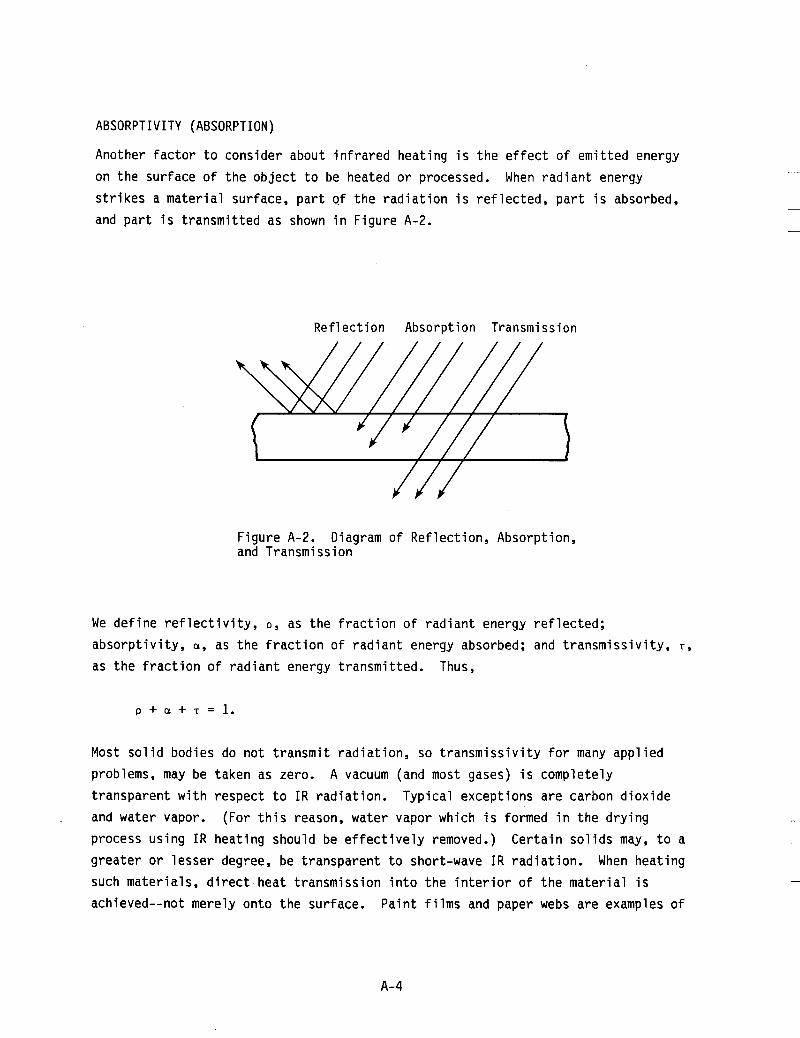
ABSORPTIVITY (ABSORPTION)
Another factor to consider about infrared heating is the effect of emitted energy on the surface of the object to be heated or processed. When radiant energy strikes a material surface, part of the radiation is reflected, part is absorbed, and part is transmitted as shown in Figure A-2.
Reflection Absorption Transmission
Figure A-2. and Transmission
Diagram of Reflection, Absorption,
We define reflectivity, p , as the fraction of radiant energy reflected; absorptivity, a, as the fraction of radiant energy absorbed; and transmissivity, T, as the fraction of radiant energy transmitted. Thus,
p + a + r = l .
Most solid bodies do not transmit radiation, so transmissivity for many applied problems, may be taken as zero. transparent with respect to IR radiation. Typical exceptions are carbon dioxide and water vapor. process using IR heating should be effectively removed.) greater or lesser degree, be transparent to short-wave IR radiation. such materials, direct heat transmission into the interior of the material is achieved--not merely onto the surface.
A vacuum (and most gases) is completely
. (For this reason, water vapor which is formed in the drying Certain solids may, to a
When heating
Paint films and paper webs are examples of
A- 4

materials that allow some penetration of I R energy. material is zero, the relationship simplifies to:
When the transmissivity of a
P + a = 1 (l7).
SHAPE FACTOR
All parts of an infrared heating system emit, absorb, and reflect I R radiation. Equations describing the exchange of direct radiation and reflected radiation between an I R heater and an oven wall, between an I R heater and the surface of a material to be heated, and between the surface of the material and the oven walls must be used to calculate precisely the heat exchange between the heat source ( I R heater) and the heat receiver (the material to be heated). coefficient and exchange coefficient (also know as "view" or "shape" factor) form part of these equations. of surfaces, and indicate the proportion of radiation from one surface to another surface inside the oven area. below and in the tabulation (1).
The emission
Exchange coefficients are dependent upon the arrangement
The equations for a number of simple cases appear
Where Pi2 = Heat exchange between surface 1 and 2(W) F12 = Exchange coefficient (see tabulation below) A = Area (m2) T = Temperature (K) u = 5.6697 x 10⁻⁸ (W/m2K4)
Geometry F17
Parallel flat surface with small 1 separation l/q+l/q-l
A surface completely surrounded 1 by another surface with small
A surface completely surrounded El
1/ E 1+1/€2- 1 separation
by a comparatively large area
A- 5

PENETRATION FACTOR
As the temperature of an IR source rises, the energy given off (1) increases in radiant efficiency, (2) decreases in wavelength, and (3 ) changes in other characteristics. One of these chqracteristics involves the penetration factor of infrared energy. than low-energy long wavelengths (5).
High-energy short wavelengths have better penetration abi 1 i ty
The penetration factor of infrared energy into an object is a function of the wavelength. The energy of a high-temperature IR source (with a short wavelength, such as a tungsten filament quartz lamp) has a greater ability to penetrate into an object than does a low-temperature IR source (with a long wavelength, such as a nickel-chrome filament quartz lamp).
Although infrared energy has penetration qualities, it cannot be viewed in the same way as radio waves that can heat from the inside out. are microwave ovens and X-ray diagnostic machines (the rays from which can penetrate through an object allowing pictures to be taken). infrared energy for most industrially processed materials is measured in thousandths of an inch, not in inches (of the order of 0 to 5
Examples of this phenomenon
The penetration of
meters).
Particular penetrating characteristics of infrared sources with different temperatures can be used advantageously for various types of industrial heating applications. For example, high-temperature (short wavelength) IR sources with greater penetration ability can be effectively used for fast baking of certain paints since the infrared energy penetrates the paint surface and forces out solvents from within. skin to form which traps solvents, subsequently initiating microscopic bubbles and other surface flaws.
Conventional (outside-in) drying methods can cause a paint
Surface heating characteristics of low-temperature (long wavelength, non- penetrating) infrared sources can be used to advantage as well. are well suited to low-temperature IR sources include: (1) dry-off of surface water on metal, plastic, or glass, (2) surface toasting/browning of foods, and (3) drying of adhesives or glues on a product for which a surface skin is desirable to allow product stacking without sticking. useful when the material to be dried or cured lies on a heat-sensitive thin substrate, such as fabric in a screen printing application.
Applications that
Low-temperature IR sources are also
A-6

Additional discussion on the utilization of different IR sources can be found in the Applications section. extremely useful in a broad variety of industrial applications. Figure A-3 depicts wavelength penetration characteristics of the three classes of IR.
Properly applied IR energy delivers results that are
COLOR SENSITIVITY
Color sensitivity is another characteristics of infrared sources related to source temperature and wavelength. The general rule relating to color sensitivity is the higher the source temperature, the higher the rate of heat absorption by darker colors (thus the greater the degree o f color sensitivity of the source). In other words, high-temperature (short wavelength) sources are more color sensitive than low-temperature (long wavelength) sources. heat source.
There is no such thing as a color-blind Sources vary in color sensitivity by degree only (4).
For example, in a typical industrial oven operating at a nominal product surface temperature of 93°C (200°F), using a tungsten filament lamp at full voltage, a black product may run as much as 13°F higher than a similar product colored medium red, green, or blue. In the same oven with a nickel-chrome filament tube, the difference between black and medium red, green, or blue might drop to approximately 8"F, whereas in the same oven with a metal sheath IR source, the difference may be as low as 6°F. tolerance for higher temperature than lighter colors, these nominal differences are 1 arge 1 y academi c .
However, since it is also true that darker colors have a greater
REFLECTORS
Since infrared energy and visible light are radiant energies, IR shares many o f the properties characteristic of light. direction of infrared energy into specific patterns by optically designed ref lectors. Reflection and direction of IR energy onto a product is important to infrared heating design because it greatly increases the overall efficiency of the heating system (5).
One such property is the reflection and
Typical reflectors spread re-directed energy for uniform heating.
In most types of infrared heating systems, reflectors are used. Sometimes, a
separate metal reflector is used, but highly reflective oven walls can serve the same function. The higher the efficiency of the reflector, the more the radiant energy will be transferred to the product. dictated by its material, shape, and contour.
The efficiency o f a reflector is
A-7

I.R. Emitter /
Ink or Coating . Layer
I ' I
Substrate
I.R. Emitter
I I
Substrate
Figure A-3. Penetration Characteristics o f IR Radiation (3)
A-8

Reflectors used for process-heating applications must not only be made of highly reflective material; they must also be able to maintain reflectivity over a long period of time, under conditions prevalent in the process. most efficient operate at lower surface temperatures, and, therefore, tend to stay cleaner. to clean. efficiency (lo).
Reflectors that are
Ceramic reflectors may carbonize outgassed products making them difficult All reflector types require periodic cleaning to maintain optimal
A reflector is not limited to the contour area directly behind the heat source; the entire oven wall must also be considered a reflector. process oven to allow entry and exit of the product must be kept to a minimum. Both batch and continuous type ovens have reflective doors that close behind the product to contain the I R energy within the oven.
Openings in any continuous
The greater the radiant component in an oven, the greater the need for good reflectors. Low temperature sources, low temperature processing, and long cycle processing can economically utilize low-cost, lower-efficiency reflectors. Conversely, high-efficiency reflectors become very important for high-temperature or rapid-throughput processing.
Ref 1 ector Materi a1 s
Due to rigid requirements, few materials can be used for reflectors in I R process heating equipment. Reflector materials must have high reflectivity of I R energy; resist corrosion, heat, and moisture; and be easily cleaned.
Pure gold, silver, or copper are the best materials for infrared reflectors. provide efficiencies of at least 20 percent above aluminum, 30 percent above
All
stainless stee reflective eff operat i ng , and copper oxidize Gold, electrop
, and 50 percent above polished chromium. These differences in ciency can make large differences in available power, cost of even required size of the oven. quickly and, therefore, do not make practical reflector coatings. ated over an inexpensive base metal such as stainless steel, was the
Of the three materials, silver and
standard I R reflector for decades. When the U.S. government de-regulated the price of gold, many IR oven manufacturers purchased a less expensive gold-anodized aluminum, which contains no gold but retains the yellow color. aluminum reflector actually absorbs (i.e., wastes) 900 percent more energy than a 98 percent gold ref lector (lo).
An 80 percent
A-9

Recent technical improvements in gold electroplating (developed for defense, aerospace, and laser firms) now provide ultra-thin gold plating with infrared reflectance above 98 percent. coating is the infrared reflectance standard materials for the National Bureau of Standards. (Laser Gold is a proprietary process of Epner Technology Incorporated of Brooklyn, New York.)
Known as Laser Gold (registered trade name), this
Because gold-coated reflectors absorb so little. IR energy, they operate at rather low temperatures and have lower cooling requirements than other types.
Aluminum is a commonly used reflector material (because of its low purchase cost) and, hence, provides economical reflectivity when properly applied. Aluminum reflectors are durable enough to withstand temperature levels present in heat applications up to 316°C (600°F). (colored) aluminum reflectors can approach 80 to 85 percent for shortwave IR. are recommended for applications where the ref lector surface can be properly maintained (cleaned). For areas where proper maintenance is not possible, a disposable, non-anodized aluminum foil covering for the reflectors may be practical.
Reflectance efficiency of new gold-anodized They
For very high temperature applications (up to 480°C [900°F]) , gold porcelain reflectors (24 K gold fired onto porcelain-coated steel sheets) are recommended. When new and properly maintained, these reflectors are approximately 95 percent efficient.
High density applications in a limited space require specially extruded aluminum reflectors. durability, compactness, and heat sink dissipation properties. A gold-plated coating significantly reduces the cooling requirements for such applications (E). Unplated aluminum reflectors are approximately 80 to 85 percent efficient when new.
Aluminum extrusions are selected for their high temperature
The efficiency of gold-plated ref can be used for applications requ
Reflector Patterns
The ability to control the direct
ectors approaches 99 percent. ring up to 650°C (1200°F) product temperature.
These reflectors
on of infrared radiation by optically-designed reflectors is a distinct feature of the infrared heat-processing methods. properly designed oven, reflectors allow all the available radiant energy inside the oven to be directed onto the product, or onto part of the product (2). When
In a
A-10
heating plastic sheets before forming, for example, different areas can be heated to different temperatures to provide desired variations of flow characteristics of the material (lo). Effective use of reflectors greatly increases oven efficiency and conserves energy by reducing waste heat. versatility and variations that can be achieved using reflectors to direct the radiant energy onto a product.
Figure A-4 illustrates the
Reflector Cooling
To assure satisfactory operating 1 ife for infrared sources and equipment, forced- or natural-movement cooling air is necessary. In extreme cases, water cooling is used. In high-temperature applications, forced cooling of the reflector, source terminals, and w ring is essential. Quartz lamps have a temperature limitation of 330°C (650°F) on the lamp end seals. This temperature can be controlled even in high-temperature applications by shielding the lamp ends from radiation, and by cooling the lamp ends with forced air. The amount of cooling and the method of cooling required for a particular application will vary depending on ambient conditions of the individual application, and other factors. for recommending general reflector cooling requirements. Conditions of each application need to be considered to determine necessary cooling requirements.
There are no criteria
A-11

. .. e a , I V
3 w o L V ) 3 tn LL
a L
*I-
A- 12

Appendix B
MANUFACTURERS OF ELECTRIC INFRARED HEATING EQUIPMENT AND SYSTEMS
BGK Finishing Systems, Inc.* 3850 Annapolis Lane Plymouth, MN 55441
Blasdel Enterprises, Inc. 1013 W. Main Street P. 0. Box 260T Greensburg, IN 47240
Casso Solar Corp. P. 0. Box 163 Pomona, NY 10970
Chromalox* Edwin L. Wiegand Division Emerson Electric Company 4 Allegheny Center Pittsburgh, PA 15212
(612) 636-6465
(812) 663-3212
(914) 354-2500
(412) 323-3900
Dry Clime Lamp Corp. Greensburg, IN
Epner Technolgy, Inc. 25 Division Place Brooklyn, NY 11222 (718) 782-5948
Fostoria Industries, Inc.* 1200 N. Main Street Fostoria, OH 44830-0986
GTE Corp. One Stamford Forum Stamford, CT 60904 1-800-828-7280 (Outside NY) 1-800-462-1075 (Within NY)
(419) 435-9201
Glenro, Inc. 39-T McBride Avenue Extension Peterson, NJ 07501
Heraeus Amersil* 650 Jerness Mill Road Sayreville, NJ 08872
North American Phillips Lighting Corp.* Specialty Lamps Products Division Bankstreet Hightstown, NJ 08520
OAL Associates, Inc. 1175-0 Industrial Ave. P. 0. Box J Escondido, CA 92025
Radiant Heat, Inc. ' Industrial Park 4T Sawyer Drive Coventry, RI
(201) 279-5900
(201) 254-2500
(201) 329-5579
(619) 743-7143
Radiant Techno1 ogy Corp. 13856-T Bettencourt Street Cerritos, CA 90701
Research , Inc. * Radiant Energy Box 24064 Mi nneapol i s , MN
Thermatronics Corp. 29-T Dwight Place Fairfield, NJ 07006
(818) 926-6518
55424 (612) 941-3300
(201) 227-6434
*Indicates company contacted for information.
B- 1