electric 09
TRANSCRIPT
8/6/2019 Electric 09
http://slidepdf.com/reader/full/electric-09 1/13
1
EEEllleeeccctttrrr iiiccc TTTrrr aaannnsssmmmiiissssss iiiooonnn LLLiiinnneeesss
Electricity: From Power Plants to Consumers
The Nature of Electricity
Electricity is generated as it is used. Unlike other commodities, there is very little ability to store electricity.Because of the instantaneous nature of the electric system, constant modifications must be made to assure
that the generation of power matches the consumption of power. The electric system we’ve grown todepend on is very complex and dynamic, ever adjusting to meet changing needs.
The amount of power on a line at any given moment depends on generation production and dispatch,customer use, the status of other transmission lines and their associated equipment, and even the weather. The transmission system must accommodate changing electricity supply and demand conditions,unexpected outages, planned shutdowns of generators or transmission equipment for maintenance, weatherextremes, fuel shortages, and other challenges.
The Transmission Grid
The electrical transmission system is more complex and dynamic than other utility systems, such as water ornatural gas. Electricity flows from power plants, through transformers and transmission lines, tosubstations, distribution lines, and then finally to the electricity consumer (Figure 1). The electric system ishighly interconnected.
The interconnectedness of the system means that the transmission grid functions as one entity. Powerentering the system flows along all available paths, not just from Point A to Point B. The system does notrecognize divisions between service areas, counties, states, or even countries.
The current transmission grid includes not only transmission lines that run from power plants to loadcenters, but also from transmission line to transmission line, providing a redundant system that helps assurethe smooth flow of power. If a transmission line is taken out of service in one part of the power grid, thepower normally reroutes itself through other power lines to continue delivering power to the customer.
In essence, the electricity from many power plants is “pooled” in the transmission system and eachdistribution system draws from this pool. This networked system helps to achieve a high reliability forpower delivery since any one power plant only constitutes a fraction of the power being delivered by thepower grid to meet the instantaneous demand requirements.
8/6/2019 Electric 09
http://slidepdf.com/reader/full/electric-09 2/13
2
This pooling of power also means that power is provided from a diversity of sources, including coal,nuclear, natural gas, oil, or other renewable energy sources such as hydropower, biomass, wind, or solarpower.
Transmission Outages
A transmission line outage acts like a dam, forcing the electricity around the blockage onto other lines. If adjacent transmission lines cannot handle the extra power flow, safety devices may switch them off toprevent damage. Further overloads can lead to cascading outages and system-wide failure, i.e., a blackout. This is one of the disadvantages of the interconnectedness of the transmission grid. Multiple failures in onelocation can quickly affect the entire system, producing a large scale blackout. This does not happen very often. For reliable power transmission, a region requires backup transmission lines with adequate capacity.Due to the 2003 Northeast blackout, the Federal Energy Regulatory Commission (FERC) passed mandatory reliability rules in 2005.
Components of the Transmission System
Power plants generate three-phase alternating current (AC). This means that there is a wire for each phasecoming out of every plant and down the transmission lines.
On a transmission structure, the three large wires are called conductors and carry the electric power. They are usually about an inch in diameter. There is also a smaller wire at the top of the structure, called a shield wire. The shield wire is designed to protect the power line from lightning. Poles with two sets of three wires (conductors) are called “double-circuit” poles. Sometimes a distribution line is strung under thetransmission lines, reducing the need for additional power poles.
Electricity is transferred from the power plant to the users through the electric grid. The grid consists of two separate infrastructures: the higher voltage transmission system and the lower voltage distribution
system. Transmission lines in Wisconsin range from 69 to 345 kilovolts (kV) and are used to minimizeelectrical losses over hundreds of miles. Extra high voltage lines, such as 500 and 765 kV lines have to-datenot been constructed in Wisconsin but are in use in other Midwest states. The lower voltage distributionsystem draws electricity from the transmission lines and distributes it to individual customers. Distributionlines range from 12 to 24 kV. The voltage that connects to your house is even lower, at 120 or 240 volts.
The interface between different voltage transmission lines and the distribution system is the electricalsubstation. Substations use transformers to “step down” voltages from the higher transmission voltages tothe lower distribution system voltages. Transformers located along distribution lines further step down theline voltages for household usage with appliances at 120 and 240 volts.

8/6/2019 Electric 09
http://slidepdf.com/reader/full/electric-09 3/13
3
Figure 1 Simplified Electric System
Transmission Line Design
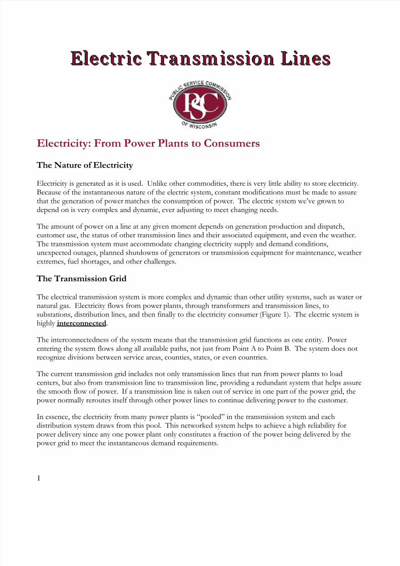
The electric lines that generate the most public interest are high-voltage transmission lines. These are thelargest and most visible electric lines. Most large cities require several transmission lines for reliable electric
service. Figure 2 shows an example of two 345-kV double-circuited transmission structures sharing thesame right-of-way (ROW). Double-circuited means that the transmission structure is carrying two sets of transmission lines, each with three conductors.
8/6/2019 Electric 09
http://slidepdf.com/reader/full/electric-09 4/13
4
Figure 2 Two High Voltage Double-Circuit Transmission Structures
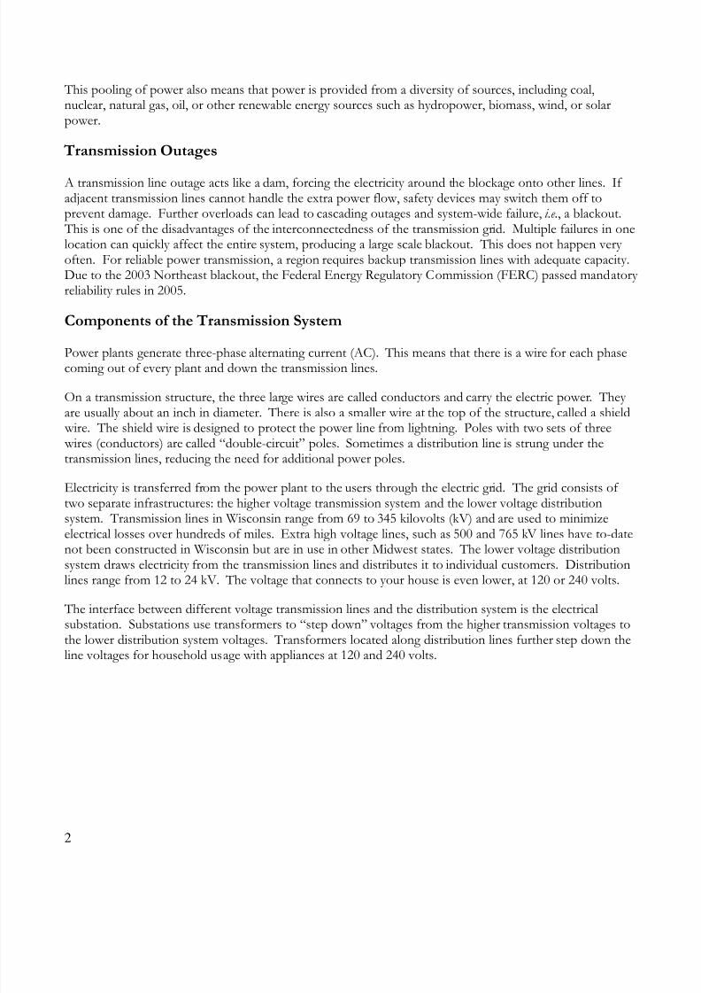
Transmission lines are larger than the more common distribution lines that exist along rural roads and city streets. Transmission line poles or structures are between 60 and 140 feet tall. Distribution line structuresare approximately 40 feet tall.
There are several different kinds of transmission structures. Transmission structures can be constructed of metal or wood. They can be single-poled or multi-poled. They can be single-circuited, carrying one set of transmission lines or double-circuited with two sets of lines. Figure 3 shows a close up of a commonly builtdouble-circuited, single-pole transmission structure. Figure 4 shows diagrams of different types of transmission structures.
Figure 3 Close-up of a Double-Circuit Transmission Structure
8/6/2019 Electric 09
http://slidepdf.com/reader/full/electric-09 5/13
5
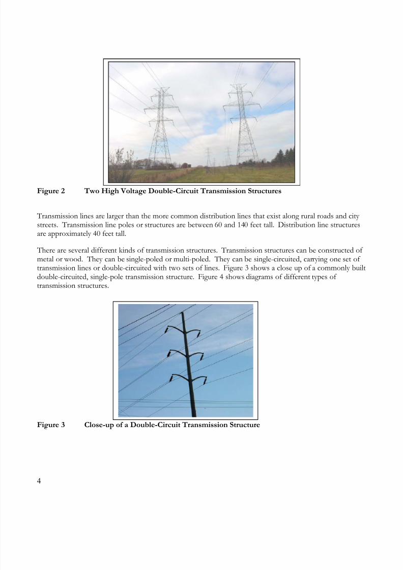
Figure 4 Different Transmission Structures
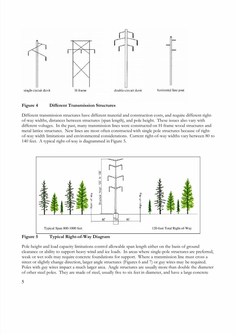
Different transmission structures have different material and construction costs, and require different right-of-way widths, distances between structures (span length), and pole height. These issues also vary withdifferent voltages. In the past, many transmission lines were constructed on H-frame wood structures andmetal lattice structures. New lines are most often constructed with single pole structures because of right-of-way width limitations and environmental considerations. Current right-of-way widths vary between 80 to140 feet. A typical right-of-way is diagrammed in Figure 5.
Figure 5 Typical Right-of-Way Diagram
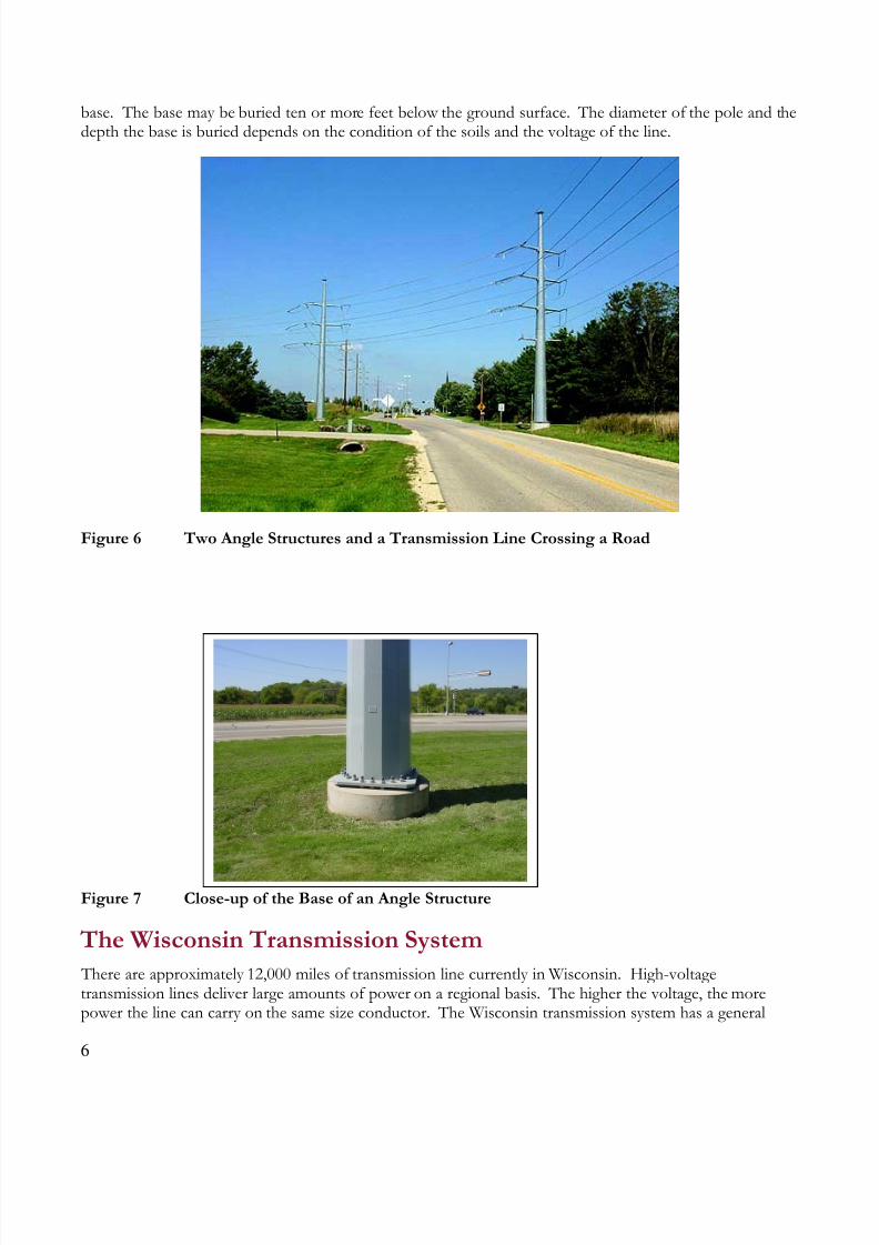
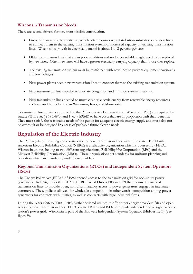
Pole height and load capacity limitations control allowable span length either on the basis of groundclearance or ability to support heavy wind and ice loads. In areas where single-pole structures are preferred, weak or wet soils may require concrete foundations for support. Where a transmission line must cross astreet or slightly change direction, larger angle structures (Figures 6 and 7) or guy wires may be required.Poles with guy wires impact a much larger area. Angle structures are usually more than double the diameterof other steel poles. They are made of steel, usually five to six feet in diameter, and have a large concrete
Typical Span 800-1000 feet 120-foot Total Right-of-Way
8/6/2019 Electric 09
http://slidepdf.com/reader/full/electric-09 6/13
6
base. The base may be buried ten or more feet below the ground surface. The diameter of the pole and thedepth the base is buried depends on the condition of the soils and the voltage of the line.
Figure 6 Two Angle Structures and a Transmission Line Crossing a Road
Figure 7 Close-up of the Base of an Angle Structure
The Wisconsin Transmission System
There are approximately 12,000 miles of transmission line currently in Wisconsin. High-voltagetransmission lines deliver large amounts of power on a regional basis. The higher the voltage, the morepower the line can carry on the same size conductor. The Wisconsin transmission system has a general

8/6/2019 Electric 09
http://slidepdf.com/reader/full/electric-09 7/13
7
electric flow from northwest to southeast through the state. The western part of Wisconsin is connected by high-voltage lines (161 and 345 kV) primarily from Minnesota. The southeastern part of Wisconsin isconnected to northern Illinois by 345 kV high voltage lines. The Wisconsin transmission system canbecome congested under normal power flow conditions. In addition, there are many transmission lines in Wisconsin that are more than 60 years old, requiring upgrades or replacement. The new Federal Reliability
Standards for transmission system design and operation require upgrades to maintain the same performancelevel. The introduction of renewable power sources such as wind development in Wisconsin and in otherMidwest states may require new high and extra high voltage transmission lines.
Restructuring the Electric Industry and Wisconsin Transmission
Up until 1999, individual utilities owned power plants, substations, transmission lines, and distribution
lines that generated and provided electricity to their customers. This system was known as vertically-integrated. In Wisconsin, the electric industry was restructured and the state’s eastern portion of the
transmission infrastructure was transferred to the American Transmission Company, LLC (ATC). ATC
commenced operation, in January 2001.
Figure 8 Transmission Companies of Wisconsin
Transmission lines in the western part of the state are owned by Xcel Energy Services, Inc (Xcel) andDairyland Power Cooperative (DPC). Figure 8 shows the approximate territories of the three companies
that own and operate transmission systems. Both Xcel and Dairyland have facilities in other states and stillown transmission and generation facilities.
8/6/2019 Electric 09
http://slidepdf.com/reader/full/electric-09 8/13
8
Wisconsin Transmission Needs
There are several drivers for new transmission construction.
Growth in an area’s electricity use, which often requires new distribution substations and new linesto connect them to the existing transmission system, or increased capacity on existing transmission
lines. Wisconsin’s growth in electrical demand is about 1 to 2 percent per year.
Older transmission lines that are in poor condition and no longer reliable might need to be replacedby new lines. Often new lines will have a greater electricity carrying capacity than those they replace.
The existing transmission system must be reinforced with new lines to prevent equipment overloadsand low voltages.
New power plants need new transmission lines to connect them to the existing transmission system.
New transmission lines needed to alleviate congestion and improve system reliability.
New transmission lines needed to move cleaner, electric energy from renewable energy resourcessuch as wind farms located in Wisconsin, Iowa, and Minnesota.
Transmission line projects approved by the Public Service Commission of Wisconsin (PSC) are required by statute (Wis. Stat. §§ 196.49(3) and 196.491(3)(d)) to have costs that are in proportion with their benefits. They must satisfy the reasonable needs of the public for adequate electric energy supply and must also notbe overbuilt or be designed in excess of probable future electric needs.
Regulation of the Electric Industry
The PSC regulates the siting and construction of new transmission lines within the state. The North American Electric Reliability Council (NERC) is a reliability organization which is overseen by FERC. Wisconsin utilities belong to two different organizations, Reliability First Corporation (RFC) and theMidwest Reliability Organization (MRO). These organizations set standards for uniform planning andoperation which are mandatory under penalty of law.
Regional Transmission Organizations (RTOs) and Independent System Operators(ISOs)
The Energy Policy Act (EPAct) of 1992 opened access to the transmission grid for non-utility powergenerators. In 1996, under that EPAct, FERC passed Orders 888 and 889 that required owners of transmission lines to provide open, non-discriminatory access to power generators engaged in interstate
commerce. These policies allowed for wholesale competition, in other words, competition among powergenerators for contracts with utilities, as well as contracts with large industrial firms.
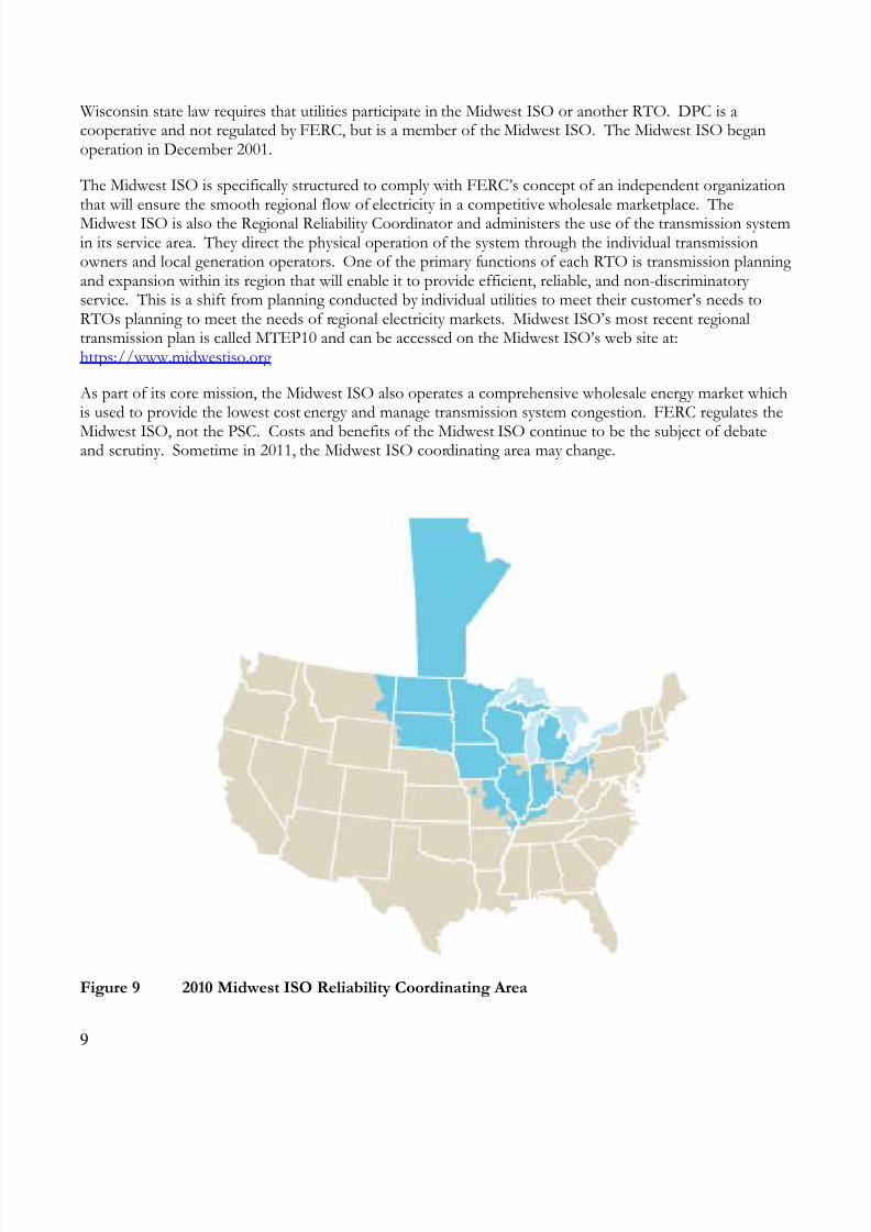
During the years 1996 to 2000, FERC further ordered utilities to offer other energy providers fair and openaccess to their transmission lines. FERC created RTOs and ISOs to provide independent oversight over thenation’s power grid. Wisconsin is part of the Midwest Independent System Operator (Midwest ISO) (Seefigure 9).
8/6/2019 Electric 09
http://slidepdf.com/reader/full/electric-09 9/13
9
Wisconsin state law requires that utilities participate in the Midwest ISO or another RTO. DPC is acooperative and not regulated by FERC, but is a member of the Midwest ISO. The Midwest ISO beganoperation in December 2001.
The Midwest ISO is specifically structured to comply with FERC’s concept of an independent organizationthat will ensure the smooth regional flow of electricity in a competitive wholesale marketplace. TheMidwest ISO is also the Regional Reliability Coordinator and administers the use of the transmission systemin its service area. They direct the physical operation of the system through the individual transmissionowners and local generation operators. One of the primary functions of each RTO is transmission planning and expansion within its region that will enable it to provide efficient, reliable, and non-discriminatory service. This is a shift from planning conducted by individual utilities to meet their customer’s needs toRTOs planning to meet the needs of regional electricity markets. Midwest ISO’s most recent regionaltransmission plan is called MTEP10 and can be accessed on the Midwest ISO’s web site at:https://www.midwestiso.org
As part of its core mission, the Midwest ISO also operates a comprehensive wholesale energy market whichis used to provide the lowest cost energy and manage transmission system congestion. FERC regulates the
Midwest ISO, not the PSC. Costs and benefits of the Midwest ISO continue to be the subject of debateand scrutiny. Sometime in 2011, the Midwest ISO coordinating area may change.
Figure 9 2010 Midwest ISO Reliability Coordinating Area

8/6/2019 Electric 09
http://slidepdf.com/reader/full/electric-09 10/13
10
Community Planning
In prior decades, electric transmission lines were constructed from Point A to Point B, in the most directmanner possible with limited concern for communities, crops, natural resources, or private property issues. As these older lines require improvements, they may be rerouted to share corridors with roads and to avoid,
where practicable, community and natural resource impacts. At the same time, continued growth in energy usage will require new electric substations and transmission lines to be sited and constructed. New andupgraded electric facilities may impact many communities and many property owners.
To meet future growth, communities often draft plans for sewers, roads, and development districts, but few cities, towns, or counties include transmission lines in their plans. Transmission lines are costly to build anddifficult to site. Cities, towns, and counties can help reduce land use conflicts by:
Dedicating a strip of land along existing transmission corridors for potential future right-of-way expansions,
Identifying future potential transmission corridors and substation sites in new developments, and
Defining set-backs or lot sizes for properties adjacent to transmission lines so that buildings don’tconstrain future use of the right-of-ways.
Being an active participant in the decision-making process will improve the ability of communities tomanage future growth and protect their resources.
Advanced Transmission Technologies
Not all new electric transmission technologies are currently ready for commercial use. Many are still in theexperimental and prototype stage. The new technologies mostly fall into two categories – new materials that
may increase the amount of power that can be safely transferred through right-of-ways, and devices thatmore finely control the flow of power. New power control devises improve the capacity of existing lines. The disadvantage of many of these new facilities and systems is that they are still being researched and theircost is extremely high.
High-Temperature Superconducting Conductivity (HTS)
The conductors in HTS devices operate at extremely low resistances and can carry five times as much poweras traditional copper wires with the same dimensions. This greatly reduces the number of new transmissionlines and the amount of new right-of-way required. However, they require refrigeration (generally liquidnitrogen) to super-cool the conductors which increases the maintenance costs and the complexity of thesystem. A few short demonstration projects have been installed to-date.
Composite Material Conductors
Usually transmission lines contain steel-core cables that support strands of aluminum wires which are theprimary conductors of electricity. New cores developed from composite materials reduce the sagging that isassociated with the high temperatures when more power goes through the transmission lines. This could becaused by a change in the network or additional generation added in one area. If the right-of-way width islimited, one might change the conductors out but keep the voltage the same. This would be less expensivefor a limited number of miles. Life-cycle costs of the newer conductors are high. Installation and

8/6/2019 Electric 09
http://slidepdf.com/reader/full/electric-09 11/13
11
maintenance procedures continue to be developed because of the difficulty in splicing the different materials while maintaining the necessary strength.
Superconducting Magnetic Energy Storage (SMES)
SMES devices could be strategically located in a transmission grid to damp out power disturbances. SMES
systems use a cryogenic technology to store energy by circulating current in a super-conducting coil,advanced line-monitoring equipment to detect voltage deviations, and inverters that can rapidly inject theappropriate combination of real and reactive power to counteract voltage problems. By correcting forpotential stability problems, these systems permit the operation of transmission lines at capacities muchcloser to their limits than currently possible. However, the high cost of these refrigeration systems and this wire is a disadvantage. These systems today have been limited to short duration energy devices used forpower quality in commercial applications.
High Voltage Direct Current (HVDC) Light
Some newer direct current systems use transistor technology rather than the conventional componentdesigns. This system design is less costly. When used with voltage-source converters, they can be designed
to mitigate a wide range of problems such as voltage flicker, harmonics, power factor, voltage sags, andinterruptions. Two current applications include a 300 MW undersea cable from Connecticut to Long Island, NY and a back-to-back HVDC, 36 MW, asynchronous connection between Mexico and Texas.
Variable Frequency Transformer (VFT)
VFT technology can be applied to controlling power flow between synchronous systems. The units areessentially a continuous variable phase-shifting transformer. They have been installed on the Hydro-Quebecsystem in Canada and on a system in Texas.
Fault Current Limiter (FCL)
The larger overlay of extra high voltage transmission often raises fault currents on high voltage systems,requiring replacement of substation equipment. FCL devices can protect the lower voltage facilities fromhigher faults so that replacement is not required. Typically high-temperature superconductor materials areused in conjunction with this system.
Wind and VAR Control
Wind generators provide a cleaner energy source but have voltage regulation, voltage stability, and VAR consumption issues. There are several vendors who provide fast-compensating (approximately ¼ of acycle) reactive devices to mitigate these issues. These devices use DC-AC technology to provide eitherleading or lagging current in a dynamic mode.
Real-time Ratings of Transmission Lines This is another use of advanced information technologies to expand the capacity of existing transmissionsystems. Special devices can measure the real-time tension in transmission lines, ambient temperature, windspeed, and/or conductor sag. The results of the measurements are telemetered to the control center whichthen adjusts the line rating accordingly. Once again the drawback with this technology is the high costrelative to the incremental potential increase in capacity.
8/6/2019 Electric 09
http://slidepdf.com/reader/full/electric-09 12/13
12
The Role of the PSC
The PSC regulates Wisconsin’s utilities. A three-member board (the Commission) is appointed by thegovernor to make decisions based on analysis provided by a technical staff with a wide range of specialties.
The PSC staff analyzes transmission line applications to see if the proposed projects are needed and todetermine the potential impacts. The size and complexity of the proposed project determines the scope of the PSC review process. The PSC considers alternative sources of supply and alternative locations orroutes, as well as need, engineering, economics, safety, reliability, potential for individual hardships, andenvironmental factors when reviewing a transmission project.
An applicant must receive a Certificate of Pubic Convenience and Necessity (CPCN) from the Commissionfor transmission line projects that are either:
345 kV or greater; or
less than 345 kV but greater than or equal to 100 kV, over one mile in length, and needing somenew ROW.
All other transmission line projects must receive a Certificate of Authority (CA) from the Commission, if the project’s cost is above a certain percent of the utility’s annual revenue.
The CPCN review process includes a public hearing in the affected project area. Members of the public areencouraged to testify to their views and concerns about the project. The CA review process does notautomatically include a public hearing, but may be determined on a case-by-case basis.
The Commission is responsible for making the final decisions about proposed transmission lines and hasthe authority to approve, deny or modify any transmission application. The Commission meets regularly inopen meetings to decide cases before them. The public can observe any open meeting. The Commission
reviews all hearing testimony from the applicant, PSC staff, Wisconsin Department of Natural Resourcesstaff, intervenors, and members of the public. The Commission makes all decisions on whether atransmission line will be built, how it is designed, and where it will be located and has the authority torequire additional environmental protections or mitigation measures.
The Public Service Commission of Wisconsin is an independent state agency that oversees more than1,300 Wisconsin public utilities that provide natural gas, electricity, heat, steam, water and
telecommunication services.
8/6/2019 Electric 09
http://slidepdf.com/reader/full/electric-09 13/13
13
Public Service Commission of WisconsinP.O. Box 7854
Madison, WI 53707-7854 Telephone: 608-266-5481 Toll free: 888-816-3831
Consumer affairs: 608-266-2001 / 800-225-7729 TTY: 608-267-1479 / 800-251-8345
Fax: 608-266-3957 Website: http://psc.wi.gov
Electric 09 (02/11)