el 675 uhf propagation for modern wireless systems henry l. bertoni polytechnic university
Post on 21-Dec-2015
216 views
TRANSCRIPT
EL 675 UHF Propagation for Modern
Wireless Systems
Henry L. Bertoni
Polytechnic University

2003 © 2003 by H.L. Bertoni 2
Context for Discussing Wireless Channel Characteristics
• Frequencies above ~ 300 MHz ( < 1 m)• Radio links in man-made environments
– At least one end is among the buildings
– Link lengths • Macrocells (20 km > R > 1 km)
• Microcells (2 km > R > 100 m)
• Picocells/indoor (R < 100 m)
– Presence of many objects with sizes from 10 cm to 100 m
– Wave interactions described by scattering and shadowing, rather than resonances

2003 © 2003 by H.L. Bertoni 3
Need to Bridge Electromagnetics (EM) and Communications (Com)
• Electromagnetics– Deals with deterministic physical environment - seek
precise solution– Field quantities are prediction output
• Communications – Deals with random processes - seek statistical solutions – Required inputs that are statistical measures of received
signal properties
• Must phrase the electromagnetic solutions in ways that can be used by communication community– Understand and predict channel characteristics

2003 © 2003 by H.L. Bertoni 4
Complimentary View Points
• Electromagnetic view point– Objects cause a rich set of ray paths connecting
transmitter and receiver (multipath)
• Communications view point– Received signal is the sum of delayed versions of the
transmitted signal (multipath)
• Interpreting the ray description of electromagnetic fields provides the channel characteristics– EM propagation governs the channel characteristics,
but signal processing governs what is observed
– Interpret ray results to predict observed statistics

2003 © 2003 by H.L. Bertoni 5
Communication Systems Drive Descriptions of the Radio Channel
• How to characterize channel depends on the radio system and link geometry – All require knowledge of the power level
• Different measures of multipath interference – Narrowband -- pulsed -- multi-frequency systems – Fast fading -- delay spread -- coherence bandwidth– Coherence distance -- angle spread -- ?
• Macrocells, microcells and indoor picocells– Different considerations of multipath interference– Slow fading statistics and range dependence vs. deterministic variations power level

2003 © 2003 by H.L. Bertoni 6
EM Effects That Need to Be Considered
• Propagation of waves through space• Reflection, transmission and diffraction
– Mechanisms by which fields get to locations not visible to the transmitter
• Radiation and reception by antennas• Ray description of radiation
2003 © 2003 by H.L. Bertoni 7
Basic Concepts
• Operation of individual radio systems is dependent on specific channel parameters -- all systems depend on received power and interference.
• Frequency re-use as a basis for increased system capacity
2003 © 2003 by H.L. Bertoni 8
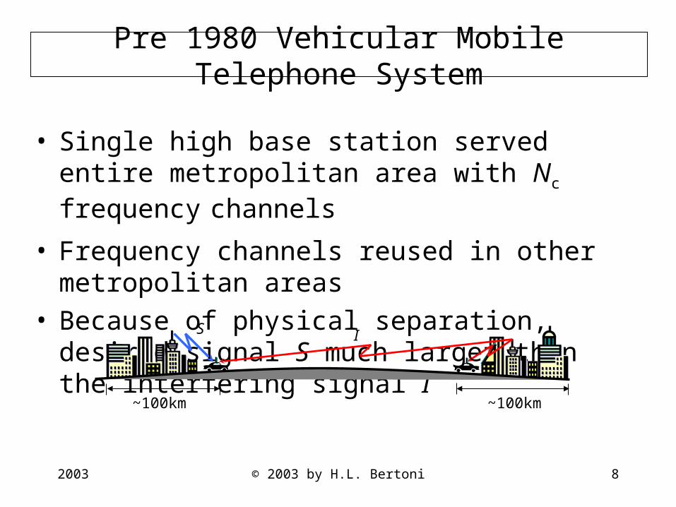
Pre 1980 Vehicular Mobile Telephone System
• Single high base station served entire metropolitan area with Nc frequency channels
• Frequency channels reused in other metropolitan areas
• Because of physical separation, desired signal S much larger than the interfering signal I
IS
~100km~100km
2003 © 2003 by H.L. Bertoni 9
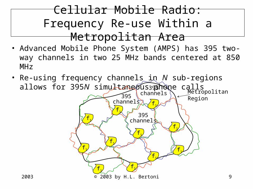
Cellular Mobile Radio:Frequency Re-use Within a Metropolitan Area
• Advanced Mobile Phone System (AMPS) has 395 two-way channels in two 25 MHz bands centered at 850 MHz
• Re-using frequency channels in N sub-regions allows for 395N simultaneous phone calls
395channels395
channels
395channels
MetropolitanRegion
f1
f1
f1
f1
f1
f1
f1
f1
f1
f1f1
2003 © 2003 by H.L. Bertoni 10
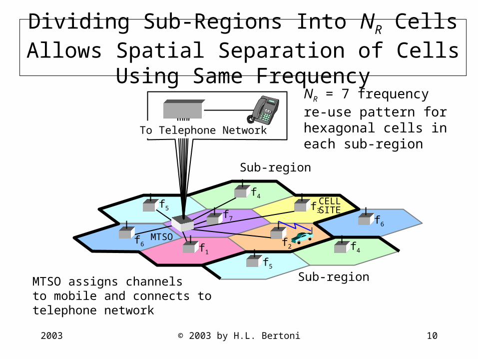
Dividing Sub-Regions Into NR Cells Allows Spatial Separation of Cells Using Same Frequency
f1
f7
f4
f5
f2
f3
f6
f4
f6
f5
MTSO
To Telephone Network
CELL SITE
Sub-region
Sub-region
NR = 7 frequency re-use pattern for hexagonal cells in each sub-region
MTSO assigns channelsto mobile and connects totelephone network
2003 © 2003 by H.L. Bertoni 11
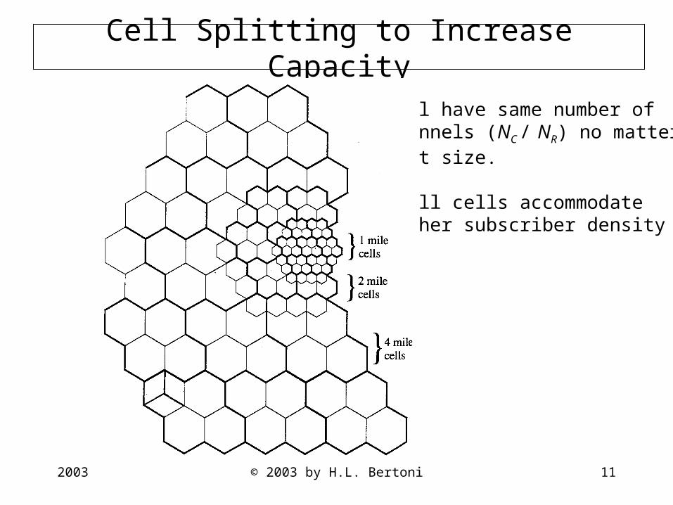
Cell Splitting to Increase Capacity
Cell have same number ofchannels (NC / NR) no matterwhat size.
Small cells accommodatehigher subscriber density
2003 © 2003 by H.L. Bertoni 12
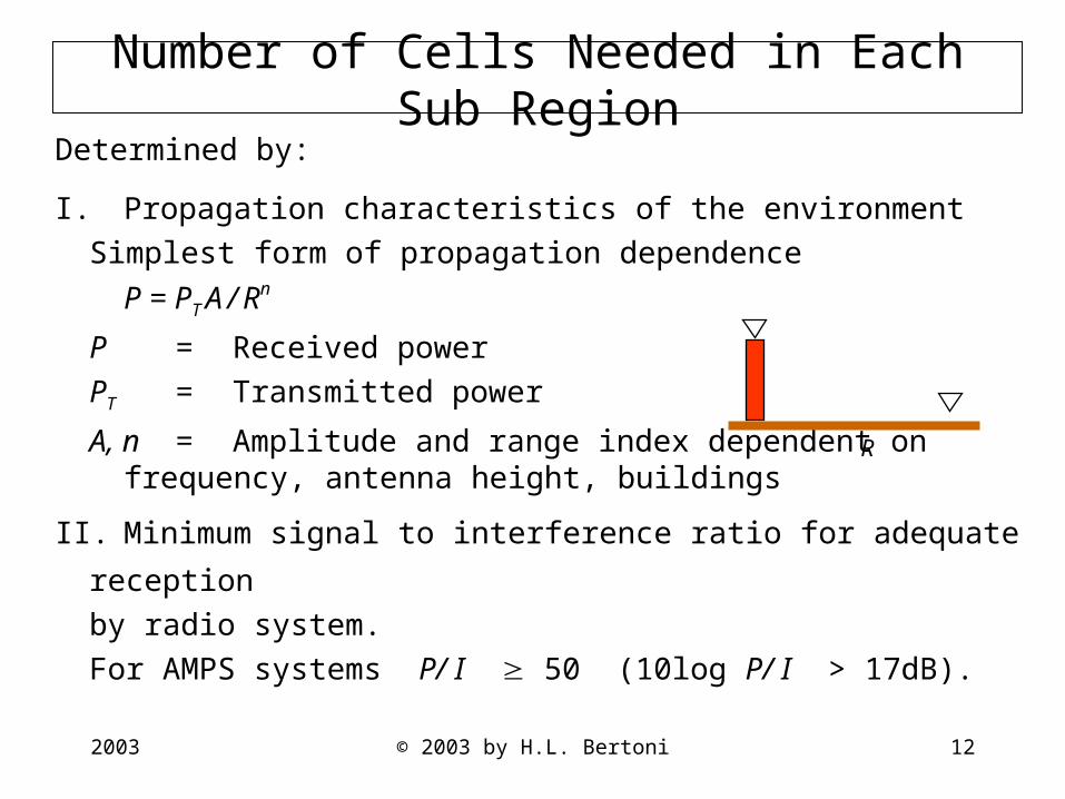
Number of Cells Needed in Each Sub Region
Determined by:
I. Propagation characteristics of the environment
Simplest form of propagation dependence
P = PT A / Rn
P = Received power
PT = Transmitted power
A, n= Amplitude and range index dependent on frequency, antenna height, buildings
II. Minimum signal to interference ratio for adequate reception
by radio system.
For AMPS systems P/ I 50 (10log P/ I > 17dB).
R
2003 © 2003 by H.L. Bertoni 13
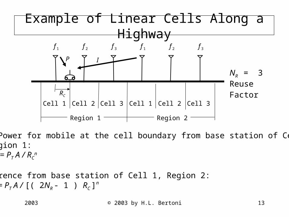
Example of Linear Cells Along a Highway
NR = 3Reuse
Factor
Signal Power for mobile at the cell boundary from base station of Cell 1, Region 1:
P = PT A / RCn
Interference from base station of Cell 1, Region 2:I = PT A / [( 2NR - 1 ) RC ]
n
f 1 f 2 f 3 f 1 f 2 f 3
Region 1 Region 2
Cell 1 Cell 2 Cell 3 Cell 1 Cell 2 Cell 3
RC
IP

2003 © 2003 by H.L. Bertoni 14
NR for Linear Cells for Different Range Index n
€
PI
⎛ ⎝
⎞ ⎠
min
≤PI
=2NR −1( )RC[ ]
n
RCn = 2NR −1( )
n
or
NR ≥12
1+ (P /I)minn[ ]
For (P /I)min =50
Accounting for interference only from the nearest co-channel cell
Condition n NR
Fre e space 2 4Flat e arth 4 2

2003 © 2003 by H.L. Bertoni 15
Frequency Re-Use Pattern for Covering Area
Symmetric patterns based onhexagonal cells have allco-channel cells located on circles.There are six cells on the smallestcircle of radius D, where
For symmetric reuse patterns
where m1, k1 are any integers.Lowest values are NR= 3, 4, 7, 9, 12, 13, 19, 21, 25, 27,31, 39.
2111
21
.3
kkmmN
NRD
R
RC
++=
=
D
RC
Co-channel cellsin the first tier

2003 © 2003 by H.L. Bertoni 16
Frequency Re-Use for S = A/R n Signal Variation
Signal Power from base stations to mobile at the cell edge
P = PT A /(RC)n
Interference power from co-channel base stations in the first tier
D
D+R
C
RC D+R
C
DRC
DRC
D
I =PTA2
D−RC( )n +
2Dn +
2
D+RC( )n
⎡
⎣ ⎢
⎤
⎦ ⎥

2003 © 2003 by H.L. Bertoni 17
NR for Symmetric Pattern of Hexagonal Cell
€
PI
⎛ ⎝
⎞ ⎠
min
≤PI
⎛ ⎝
⎞ ⎠ =
12
RCD−RC
⎛
⎝ ⎜ ⎞
⎠ ⎟ n
+RCD
⎛ ⎝
⎞ ⎠
n
+RC
D+RC
⎛
⎝ ⎜ ⎞
⎠ ⎟ n
=0.5
1D RC( )−1
⎛
⎝ ⎜ ⎞
⎠ ⎟ n
+1
D RC
⎛
⎝ ⎜ ⎞
⎠ ⎟ n
+1
D RC( )+1
⎛
⎝ ⎜ ⎞
⎠ ⎟ n
If (P /I )min =50, and since D =Rc 3NR , then
50≤0.5
13NR −1
⎛
⎝ ⎜
⎞
⎠ ⎟
n
+1
3NR
⎛
⎝ ⎜
⎞
⎠ ⎟
n
+1
3NR +1
⎛
⎝ ⎜
⎞
⎠ ⎟
n
Condition n NR
Fre e space 2 101Flat e arth 4 7
2003 © 2003 by H.L. Bertoni 18
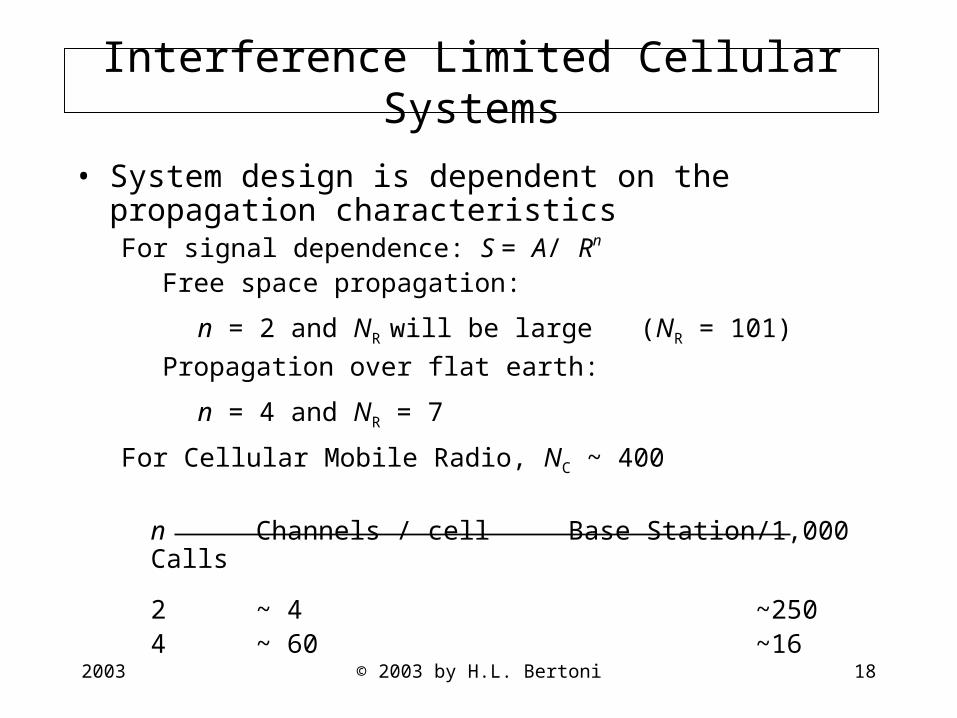
Interference Limited Cellular Systems
• System design is dependent on the propagation characteristics For signal dependence: S = A/ Rn
Free space propagation:
n = 2 and NR will be large (NR = 101)
Propagation over flat earth:
n = 4 and NR = 7
For Cellular Mobile Radio, NC ~ 400
n Channels / cell Base Station/1,000 Calls
2 ~ 4 ~2504 ~ 60 ~16
2003 © 2003 by H.L. Bertoni 19
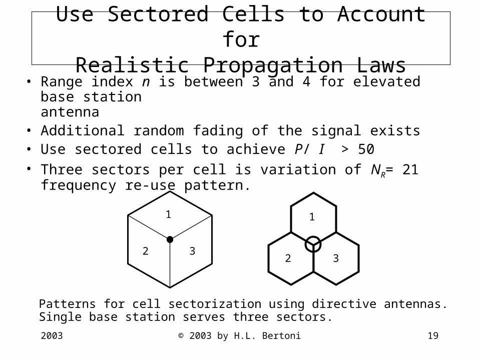
Use Sectored Cells to Account forRealistic Propagation Laws
• Range index n is between 3 and 4 for elevated base stationantenna
• Additional random fading of the signal exists• Use sectored cells to achieve P/ I > 50• Three sectors per cell is variation of NR= 21 frequency re-use
pattern.
2 3
1
2 3
1
Patterns for cell sectorization using directive antennas.Single base station serves three sectors.
2003 © 2003 by H.L. Bertoni 20
Effect of Range Index n on Down Link System Capacity for CDMA System
• Same frequency used to communicate to subscribers in all cells.
• Different code used for each subscriber.
• Signals to subscribers in other cells act as interference.
• Subscribers in same cells have orthogonal codes, but multipath
interference results in some interference.
• Subscriber can receive same signal from up to three base stations.
• For adequate reception, I FP, where the value of F > 1 depends processing gain, voice activity factor, etc.
2003 © 2003 by H.L. Bertoni 21
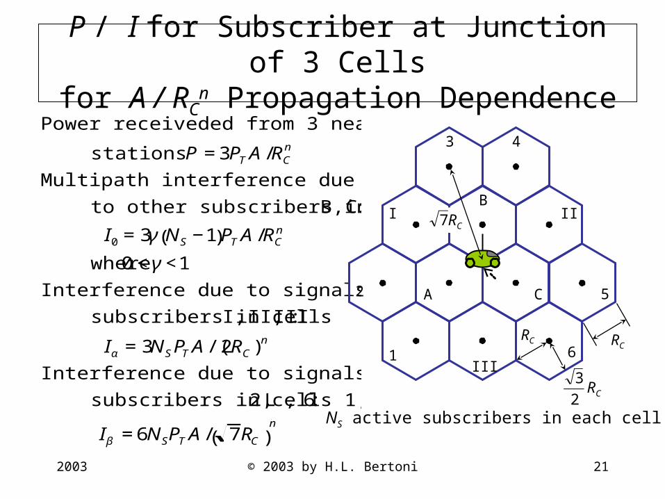
P / I for Subscriber at Junction of 3 Cellsfor A / RC
n Propagation Dependence
€
Power receiveded from 3 nearest base
stations: P =3PTA/RCn
Multipath interference due signals sent
to other subscribers in cells A, B, C:
I0 =3γ NS −1( )PTA/RCn
where 0<γ<1
Interference due to signals sent to
subscribers in cells I, II, III :
Iα =3NSPTA/(2RC)n
Interference due to signals to
subscribers in cells 1, 2, L , 6:
Iβ =6NSPTA/ 7RC( )n NS active subscribers in each cell
CR2
3
1
2
3 4
5
6
A
B
C
I II
III
RC
CR7
RC
2003 © 2003 by H.L. Bertoni 22
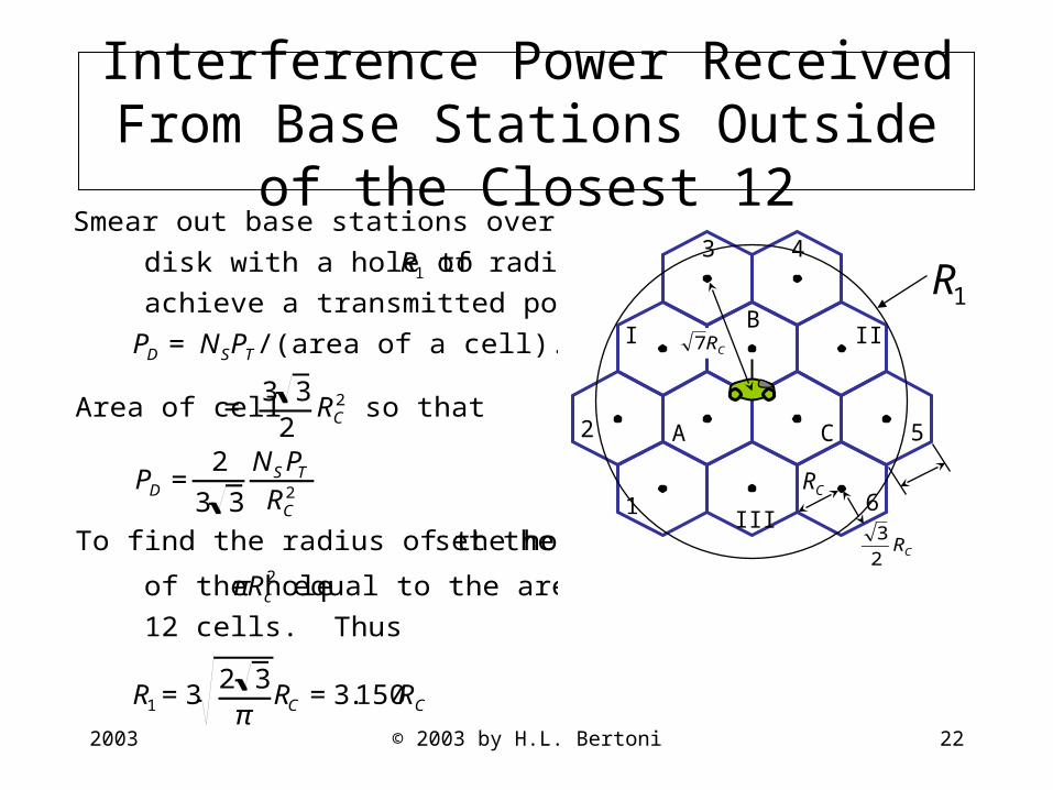
Interference Power Received From Base Stations Outside of the Closest 12
€
Smear out base stations over an infinite
disk with a hole of radius R1 to
achieve a transmitted power density
PD = NSPT/(area of a cell).
Area of cell = 3 32
RC2 so that
PD =2
3 3
NSPTRC
2
To find the radius of the hole, set the area
of the hole πRc2 equal to the area of the
12 cells. Thus
R1 =32 3π
RC =3.150RC
CR2
3
1
2
3 4
5
6
A
B
C
I II
III
CR7
RC
R1

2003 © 2003 by H.L. Bertoni 23
Interference Received From Smeared Out Base Stations on the Infinite Disk
€
Interference power = ID = Tx power density( )∫∫ ARn
⎛ ⎝
⎞ ⎠
area element( )
For circular symmetry
ID =2
3 3
NSPTRC
2
⎛
⎝ ⎜ ⎞
⎠ ⎟
R1
∞
∫ ARn
⎛ ⎝
⎞ ⎠
2πRdR( ) =4π
3 3NSPT
ARC
2
dRRn−1
R1
∞
∫
If n≤2, then ID =∞
If n>2, then
ID =4π3 3
NSPTARC
2
1(n−2)R1
n−2 =4π3 3
NSPT(n−2)
A(3.15)(n−2)RC
n
=2.418
(n−2)(3.15)(n−2)NSPTARCn

2003 © 2003 by H.L. Bertoni 24
€
Total interference I =Io +Iα +Iβ +ID . For adequate reception
I ≤F Signal Power( ) =F3PTARCn
For n≤2: ID =∞ so that capacity NS =0
For n>2: I =PTARCn 3γ(NS −1)+3
NS
2n+3
2NS
( 7)n+
2.418(n−2)(3.15)(n−2)Ns
⎡
⎣ ⎢ ⎤
⎦ ⎥
Reception requirement gives
NS γ+12n
+2
( 7)n+
2.4183(n−2)(3.15)(n−2)
⎡
⎣ ⎢ ⎤
⎦ ⎥ ≤F +γ
To see the role of n, recall that F >1 and suppose that γ=0.1
If n=4: NS ≤(F +0.1) 0.224=4.47(F +0.1)
If n=3: NS ≤1.70(F +0.1)
P/I Requirement and Capacity Ns

2003 © 2003 by H.L. Bertoni 25
Conclusions
Modern systems employ frequency re-use to increase capacity
Wireless systems employing frequency re-use are interference limited
It is necessary to balance coverage and interference
Design of Systems to accommodate a given number of subscribers is dependent on the propagation characteristics
Higher values of range index n allow for less base stations to cover a given area
Other channel characteristics will influence system design
Random spatial fading
Doppler spread, time delay spread