ehs requirements in the design of vent & relief systems
TRANSCRIPT
Confidential to Members of EPSC Report No 26
EHS Requirements in the Design of Vent & Relief Systems
1
EHS Requirements in the Design of Vent & Relief Systems
Report based on the work of the EPSC Vent and Relief Systems Working Group
EPSC 2003 The information held in this report is given in good faith and belief in its accuracy, but does not imply the acceptance of any legal liability or responsibility whatsoever by the European Process Safety Centre, or by the authors, for the consequence of its use or misuse in any particular circumstances. Any enquires about this report, or other EPSC matters, should be addressed to Mr Lee Allford, Manager - EPSC Operation
2
The European Process Safety Centre
Objectives 1. Information
To provide advice on how to access safety information and whom to consult, what process safety databases exist and what information on current acceptable practices is available.
2. Research and Development
To collect European research and development (R&D) needs and activities in the safety and loss prevention field, to inform members accordingly, to act as a catalyst in stimulating the required R&D and to provide independent advice to funding agencies priorities. “R&D” here includes experimental research and the development and review of models, techniques and software.
3. Legislation and Regulations
To provide technical and scientific background information in connection with European safety legislation and regulations, e.g. to legislative bodies and competent authorities.
4. Education and Training
To provide a single source of information on training materials for: (a) the teaching of safety and loss prevention at undergraduate level; and (b) courses and materials for training and continuing education at all levels of the workforce
Benefits of Membership
Improved cross-European co-ordination on safety standards
Identification of areas where manuals and guidelines could be produced
Improved co-ordination of safety R&D and handling of complex technical research programmes
Stimulation of R&D in areas where there are gaps in knowledge
Transfer of knowledge from elsewhere to Europe and between European countries
Technical input to legislators and standard makers to ensure more realistic legislation
Sharing and dissemination of information on safety technology and accident prevention
Access to information from a single source
3
CONTENTS
1. Background To The Working Group .................................................................... 5
1.1 Introduction ...................................................................................................... 7
2. Principal Hazards Of Combined Vent & Relief Systems ....................................... 9
2.1 Explosions ...................................................................................................... 9 2.1.1 Flammability Limits ..................................................................................................................... 9 2.1.2 Limiting Oxygen Concentration .................................................................................................. 9 2.1.3 Three Component Diagram (Flammability Triangular Diagram) .............................................. 10 2.1.4 Ignition Sources ........................................................................................................................ 11 2.1.5 Flame Propagation ................................................................................................................... 13 2.1.6 Deflagration To Detonation Transition ..................................................................................... 14 2.1.7 Combustible Dusts .................................................................................................................... 15
2.2 Chemical Reaction & Mixing ............................................................................ 16 2.2.1 Cross Contamination................................................................................................................. 16 2.2.2 Weather .................................................................................................................................... 19
2.3 Mechanical Considerations ............................................................................. 19 2.3.1 Reaction Forces ......................................................................................................................... 19 2.3.2 Liquid Slugs ............................................................................................................................... 19 2.3.3 High Transient Flows ................................................................................................................ 20 2.3.4 Thrust Restraint Design ............................................................................................................ 21 2.3.5 Vibration & Relief Valve Chatter ............................................................................................... 21
2.4 Practical Problems .......................................................................................... 22 2.4.1 Flame Arrestors- Fouling And Plugging Potential ..................................................................... 22 2.4.2 Deposits In Areas Of No Flow.................................................................................................... 23 2.4.3 Air Ingress Into Vent/Flare Systems .......................................................................................... 25
3. System Design Philosophy, Inherent Safety & Sustainable Development .......... 28
3.1 Inherent Safety ............................................................................................... 28
3.2 Sustainable Development ............................................................................... 28
3.3 Examples Of Application Of Inherent Safety To Vent Systems .......................... 29
3.4 Examples Of Application Of Inherent Safety To Relief Systems......................... 30
4. System Design ................................................................................................. 32
4.1 Objectives .................................................................................................... 32
4.2 Data Collection ............................................................................................... 32
4.3 Selection & Specification Of Vent Or Relief System ......................................... 33
4.4 Ensure Thorough Understanding Of Material Within System ........................... 33
4.5 Define System Pressure Limits ......................................................................... 35 4.5.1 Back Pressure ............................................................................................................................ 35
4.6 Define System Temperature Limits .................................................................. 36
4.7 Material Selection ........................................................................................... 37
5. Hazard Assessment .......................................................................................... 40
5.1 Chemical Reaction Hazard Matrix .................................................................... 40
5.2 Hazard Identification ....................................................................................... 40
5.3 Hazard Analysis – HAZAN ................................................................................ 41
5.4 Classification Of Hazardous Areas .................................................................... 41
5.6 Assessing Sources Of Ignition .......................................................................... 44
4
5.7 Explosion Hazard Matrix ................................................................................. 44
5.8 Blowers, Compressors And Fans ...................................................................... 48
5.9 Piping Systems ................................................................................................ 48
5.10 Application To Existing Vent And Relief Systems .............................................. 49
6. Protective Measures ........................................................................................ 51
6.1 Hydraulic (Liquid) Seals ................................................................................... 51
6.2 Dry Flame Arresters ........................................................................................ 53
6.3 Explosion Suppression ..................................................................................... 53
6.4 Explosion Isolation .......................................................................................... 55
7. Management Of Change (MOC) ....................................................................... 56
7.1 When do we call it a change? .......................................................................... 56
7.2 What does it take to handle the change, how do we have tomanage it? ......... 57
7.3 Where does the technical work start? ............................................................. 57
7.4 The next step before the implementation of the change is as follows: ............. 57
7.5 The idea is taking shape .................................................................................. 58
7.6 The safety check ............................................................................................. 58
7.7 Record the safety check .................................................................................. 59
7.8 Conclusion .................................................................................................... 59
Appendix 1 - Le Chatelier’s Rule, To calculate flammablity limits .................................. 60
Appendix 2 - Three Component Diagram (Flammability Triangular Diagram) ............... 61
Appendix 3 - Explosion in a Pipeline ............................................................................ 63
Appendix 4 - Explosion within a Thermal Oxidizer ........................................................ 65
Appendix 5 - EPSC Inherent Safety Statement .............................................................. 68
Appendix 6 - Chemical Internatction Performa ............................................................ 70
Appendix 7 - Classification of equipment and treatment processes ............................. 72
Appendix 8 - Where this guide complies with Atex Directive 94/9/EC ........................... 74
Appendix 9 - Flare Stack Seals ..................................................................................... 75
Glossary of Terms .................................................................................................... 76
5
1. Background to the Working Group
During a ‘Mutual Joint Visit’ of European regulators in March 2000, concerns were raised about the impact of environmental control measures on chemical plant safety. From this meeting a document was produced by the Irish Health and Safety Authority to identify the key safety issues for manifold systems and identify some sources of available information. This document was circulated to EPSC members and a number of responses were collated and sent to the Irish HSA in May 2001. At the Autumn 2001 Technical Steering Committee (TSC) it was decided that EPSC should form its own contact group to work on this topic and so a position paper was produced and circulated to EPSC members. This position paper was based on Peter Hunt’s paper “VOC Abatement and vent Collection Systems- a structured approach to safe design”. In addition Ciba Specialty Chemicals made available to EPSC members their internal technical guidance notes ‘Explosion Protection in exhaust gas collection systems for centralised treatment’. From this position paper the Manifold Vent and Relief Systems working group was established in February 2002, with the aim to review existing guidance for the design of common/manifold vent & relief systems taking into account of the needs of speciality & batch chemical manufacture. The first meeting was held at Bayer, Leverkusen in February 2002 and since then four other meetings have taken place. The initial meetings were chaired by the EPSC Technical Director, Robin Turney and later meetings by Jean-Claude Adrian, Atofina. During these meetings the structure of the guidance report was created and modified several times until a general consensus was reached. At the final meeting, a title for the EPSC guidance report was agreed to be EHS Requirements in the Design of Vent & Relief Systems. The report was prepared by Karl McManus, EPSC Technical Officer.
6
Below is a list of the Working Group Members and their company’s who took part in the exchange of information on this topic Jean Claude Adrian Atofina Klaus Joerg BASF AG Ernst Molter Bayer AG Joachim Sommer BG Chemie Fritz Altorfer Ciba Specialty Chemicals Robin Turney EPSC Karl McManus EPSC Frank Westphal Siemens Axiva Sabatino Ditali Snamprogetti Enrico Platto Snamprogetti Dominique Balthasart Solvay SA Klaus Schwenzfeuer Swiss Institute of Safety & Security Acknowledgements Particular thanks are due to Ciba Specialty Chemicals who contributed their internal technical guidance document noted above.
7
1.1 Introduction
Incident 1: Explosion within a Thermal Oxidizer A Thermal Oxidizer exploded severely damaging all sections of the oxidizer due to a Volatile Organic Compound (VOC) loading well in excess of design conditions, which created combustible concentrations of VOC's inside the oxidiser. The incident resulted in a prolonged plant outage but fortunately no staff were injured. The process operated on the site included a number of batch process vessels handling a volatile organic solvent. Environmental regulations required a reduction in the VOC discharges and a decision was made to install a vent treatment system consisting of a vent collection system and the thermal oxidiser. The site staff decided to manage the project directly with the equipment supplier without involving central engineering resources. Vent gas samples were taken and used as a basis for design of the thermal oxidiser. However no mass balance was carried-out and for this reason the design loading specified for the oxidiser did not take account of variations in VOC loading due to plant load, cooling water temperatures or the timing of batches. This resulted in the unit being grossly undersized. Root Causes The project was designed, constructed and commissioned without any written process description. Therefore the operators design intent was not consistent with the system furnished by the oxidiser contractor
There was no mass balance or process estimate of the VOC loading. Therefore, there was no basis for evaluating the validity of the emissions sampling used as the basis of the design
The possibility of high VOC loading was not identified as a hazard during the HAZOP study
The lack of understanding by the operator resulted in the design of an inappropriate safety interlock system which did not protect the unit in cases of high VOC loading
The lack of formal commissioning procedures allowed the oxidizer to be started with discrepancies existing between the HAZOPed design and the as built design
During the three and a half months of operation, when the unit shut down over seventy-five times due to ‘flame out’ trip or high temperature, neither the operator nor the contractor identified the problem correctly or took the necessary corrective action. Note: See Appendix 4 for more details of this incident
8
Almost all processes will involve some vent streams or other discharges to the atmosphere. It is recognised that any impact which these may have on the environment needs to be minimised and for this reason a number of vent or relief streams often need to be brought together for treatment. The combination of streams may introduce a number of new hazards and an increase in the risks to people, to the environment and to the business. Unless great care is directed to the design and assessment of the system, incidents, such as the example noted above, may result. This guide draws on the experience of EPSC members in order to assist in the design and assessment of systems that will be safe to operate.
Chapter 2 provides a brief description of the principal hazards that may be encountered in vent & relief systems. This chapter includes a listing of selected references
The system design philosophy, inherent safety and sustainable development are all discussed in chapter 3
In Chapter 4 an approach to the safe design of systems is outlined.
Chapter 5 describes the safety assessment of both new and existing systems. Special attention is given to the avoidance of explosion hazards
Some of the protective measures which may be incorporated into systems are described in Chapter 6
Finally management systems which are necessary for safe operation are outlined in Chapter 7
In order to prevent any misunderstanding it is important to define at the start of the report, the following:
Vent Streams
Discharges of gases and vapours which arise in normal operation including start-up and shut-down
Relief Streams
Discharge from systems (Relief Valves) installed to protect equipment from over pressurization
Vent or Relief Systems
The piping/vessels/equipment necessary for safe and environmentally acceptable discharge
9
2. Principal Hazards of Combined Vent & Relief Systems
The design of safe vent and relief systems requires a sound understanding of the principal hazards which may arise within these systems. A brief overview of these hazards is provided in this chapter together with selected references where the reader may obtain more information.
2.1 Explosions
2.1.1 Flammability Limits
Combustion can only occur between defined limits which are specific for an individual compound. These limits, Upper and Lower Flammable Limits, UFL/ LFL need to be obtained from standard references or by comparison with similar compounds. Where a number of flammable materials are present, flammable limits for the mixture may be obtained by using Le Chatelier’s Rule- see appendix 1.
2.1.2 Limiting Oxygen Concentration One of the most widely used methods of preventing deflagrations and detonations is oxidant concentration reduction. This method can be applied to process equipment and vent manifold systems. The prevention of deflagrations or detonations can be accomplished by either inerting or fuel enrichment. In the case of inerting, the oxidant (usually oxygen) concentration is reduced by the addition of inert gas to a value below the limiting oxidant concentration (LOC) see three-component diagram below. Values of the LOC for many gases and dusts can be found in reference 13. Some inert gases commonly used in industry are nitrogen, steam, carbon dioxide and rare gases. As with three component diagrams, Le Chatelier’s rule can be used to determine LOC for mixtures. In the design of inerting systems one must provide sufficient inerting gas to assure not only that the normal process conditions are rendered non flammable, but also that any credible alteration of the process environment remains outside the combustible limits. Where a condensable vapour such as steam is used as a diluent, consideration must be given to the dew point and the composition changes from condensation.
A safety margin between the LOC and the normal oxidant concentration in the process equipment or piping system is mandated by reference 13 as follows:
1. Where the oxidant concentrations is continually monitored, a safety margin of at least 2 volume percent below the measured worst credible case LOC shall be maintained, unless the LOC is less than 5 volume percent, in which case, the equipment or piping shall be operated at no more than 60 % of the LOC.
10
2. Where the oxidant concentration is not continually monitored, the oxidant concentration shall be maintained at no more than 60% of the LOC or 40% of the LOC if the LOC is below 5 volume percent. If the oxidant concentration is not continually monitored the oxidant concentration shall be checked on a regularly scheduled basis.
Incident 2: Explosion due to Oxygen Content A number of large tanks, about 1000m3 (220,000 gal) in volume, were nitrogen blanketed. To save nitrogen the tanks were connected to a gasholder. When a tank was filled, nitrogen was pushed into the gasholder. When a tank was emptied nitrogen was drawn out of the gas holder. The system leaked; there were no regular tests and the ‘nitrogen’ contained about 15% oxygen. An explosion occurred in one tank- the source of ignition was never identified with certainty. Lessons Learned: After the incident, the nitrogen blanketing system was properly maintained and daily checks were made to see that:
The oxygen content was below 5%
All the tanks were connected to the blanketing system
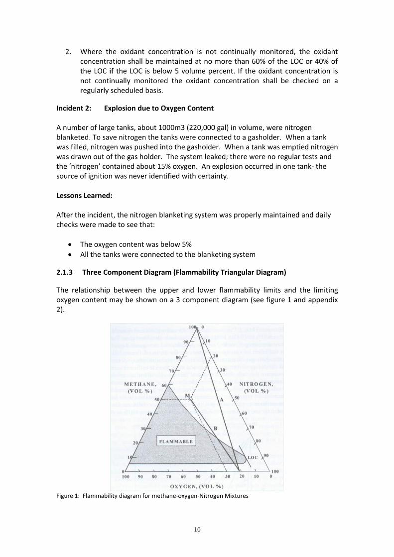
2.1.3 Three Component Diagram (Flammability Triangular Diagram)
The relationship between the upper and lower flammability limits and the limiting oxygen content may be shown on a 3 component diagram (see figure 1 and appendix 2).
Figure 1: Flammability diagram for methane-oxygen-Nitrogen Mixtures
11
2.1.4 Ignition Sources The following sources of ignition need to be considered
a. Static charges b. Operational ignition sources c. Incidental ignition sources
a) Static Charges In order for a static charge to be a source of ignition, four conditions must be fulfilled
The rate of change generation must exceed the rate of dissipation, so charge can accumulate
A static discharge must coincide in time and space with a flammable atmosphere
The effective energy of the static discharge must exceed the ignition energy of the local mixture
A locally ignited flame must propagate into a surrounding flammable atmosphere
The minimum ignition energy (MIE) of gases varies with fuel-oxidant composition. The lowest minimum ignition energy (LMIE) of most gases in air is typically less than 1mJ and occurs close to the stoichiometric concentration. The LMIE corresponds to the most easily ignitable, or “optimum” gas composition determined using an optimised spark circuit. See references 1, 3 and 5 for more information. b) Operational Ignition Sources Operational ignition sources are those which it is known from experience may occur in the event of malfunctions. Mechanical sparks or showers of sparks from equipment with rotating parts are more important in this category. From a survey of 174 incidents involving dust explosions, mechanical sparks were identified as ignition source in 30% of the cases and mechanical heat in 10% of the cases, i.e. mechanical causes accounted for nearly half of the incidents. See reference 1 for more information. Hot surfaces are also a source of ignition, and can occur on items of process equipment that use heat, such as heaters, dryers, steam and heating medium pipes, electrical equipment, etc. They also occur in less obvious process equipment too, such as engines, blowers, mechanical conveyors, mills, mixers, bearings and unprotected light bulbs. Surface effects can result in rusty surfaces igniting gas mixtures below the auto-ignition temperature measured under laboratory conditions. Dust lying on hot surfaces can be ignited, as can dust clouds, thus leading to dust explosions. Dust lying on hot surfaces also acts as a layer of insulation which can cause equipment failure. Partial oxidation or ‘ageing’ of dusts can lower the auto-ignition temperature.
12
The following measures can help minimise the chance of ignition from hot surfaces:
Prevent/Remove dust on hot surfaces
Shield or isolate hot surfaces
Only use electrical equipment approved for use in the presence of combustible dust
Regular and thorough inspection and maintenance procedures
Locate hot piping (carrying heating medium line) above process line in the pipe-rack
c) Incidental Ignition Source In a plant, effective management systems and supervision should be in place to exclude trivial ignition sources (e.g. unauthorised welding or smoking) by organisational means.
Incident 3: Explosion due to Present Ignition Source An explosion and fire took place after start up of a solvent recovery plant. The explosion centred on a solvent storage tank causing substantial damage to the tank and connecting pipework. I investigation revealed that a number of small errors combined to cause the explosion. The most likely cause of the incident was the overheating of a seal pot heater causing ignition of flammable vapours from the tank once the heater had blown. The events leading up to ignition were
Due to a pressure surge associated with start-up, the seal pot blew ejecting water
The weather was cold and the electrical heater was switched on
Since the heater element was no longer immersed, it overheated and ignited flammable vapours flowing through the unsealed vent
The flame travelled back through the vent into the tank to cause the explosion
Lessons Learned The heater was specified so that the maximum surface temperature was well below the auto ignition temperature of the solvent vapours. However a vital point was missed, that this only guaranteed whilst the element was immersed. Tests after the incident confirmed that when dry, the surface temperature rose well above the auto ignition temperature.
Incident 4: Explosion due to accidentally introduced Ignition Source An explosion and fire occurred in a formaldehyde plant. The raw material methanol, was stored in three tanks. A common vent line led to a vapour recovery unit some distance away. There was a flame trap in this line about 25 m from the recovery unit. Some old piping near the recovery unit was being dismantled by burning off bolts. One of the bolts fell near the end of the vent pipe and ignited the vapour. It is not clear why
13
the vent line was disconnected from the recovery unit. The flame travelled back up the vent line, splitting it open halfway along, passed through the flame trap and blew off the three storage tanks. Lessons Learned Nitrogen blanketing would have prevented the incident but it is not usually recommended for conducting liquids such as methanol as there is little or no chance of static electricity spark igniting the vapour (provided the equipment is earthed). However it should be considered if several tanks have to be connected to a common vent system. Incident 5: Explosion due to Static Electricity An employee was repairing a blower on the vent stack of a dissolver. When he had finished the work, he switched the machine on, but observed that it was not operating. He reached into the stack to give the fan blades a turn and there was an explosion. The vent stack had contained a flammable mixture which was probably ignited by static electricity from the man’s body.
2.1.5 Flame Propagation In order to predict the consequence of explosions in long vessels with confidence it is essential to understand the mechanisms by which overpressures are generated in vented explosions. The following description is drawn from reference 2. Four different stages of the explosion process have been identified. At each stage a pressure peak may be produced which depending on the particular conditions, may give the maximum pressure. Following build-up of a flammable gas-air mixture within an enclosure, if ignition occurs, the pressure inside the enclosure will start to increase as the flame burns spherically into the mixture, producing high temperature combustion products. The relief vent does not open instantaneously when the required pressure is reached as the vent cover has to be accelerated away from the vent opening before outflow can be established. When the explosion relief vent opens the initial outflow of gases through the vent will normally consist of cool unburnt mixture. Once the flame reaches the vent, the gases are at high temperature and therefore of lower density. This causes the volume rate of venting to increase by up to three times, which may cause the pressure to fall slightly. At this point, the atmosphere outside the vent consists of flammable mixtures previously expelled, which ignites and burns rapidly because it is turbulent. This results in the generation of an external pressure pulse which can further increase the pressure inside the enclosure by temporarily reducing the pressure differences across the vent.
14
After the rapid combustion of the external cloud outside the vent, the flame continues to expand within the enclosure. As the surface area of the flame increases, so too does the rate of production of burnt gases. Therefore the pressure continues to rise until the flame front reaches the walls of the enclosure and starts to extinguish, resulting in a decrease in the flame area. This process results in the generation of a broad pressure peak. Under certain conditions as the flame approaches the walls of the enclosure, the flame front may become unstable through interaction with acoustic oscillations set up in the enclosure. This occurs when the enclosure is empty and the acoustic losses are small. Under favourable conditions the instability in the flame can produce a very high combustion rate associated with strong pressure oscillations, which can produce a net average pressure rise at the end of the explosion process. In cases where the vent is located far from the point of ignition, the flame is observed to become elongated and accelerate towards the vent. This produced a significant pressure rise up to the peak. This is because at this stage combustion is rapid as a result of the accelerating flame, but only unburnt gas is being vented.
2.1.6 Deflagration to Detonation Transition During the normal course of an explosion in a pipeline, a pressure wave moves ahead of the flame front. At high flame velocities this pressure wave in the unburnt mixture can turn into a shock wave, which advances with supersonic speed; in the case of a detonation, it is coupled with the flame front. The velocity of a gas detonation depends largely on the composition of the flammable mixture. The detonation range is narrower than the explosion range, see reference 5 for more information. Deflagration-to-detonation transition DDT is the transient phenomenon resulting from the acceleration of a deflagration flame to detonation via combustion –generated turbulent flow and compressive heat effects. At the time of transition, a volume of pre-compressed, turbulent gas ahead of the flame front detonates, developing unusually high velocity and overpressure. The overpressure depends on the degree of pre-compression due to deflagration before transitions occurs, and can be enhanced by shock wave reflections. During the DDT, the initial peak pressure reached is higher than the final pressure reached when the stable detonation phase occurs, and the detonation is described as “overdriven”. The detailed mechanisms by which DDT occurs is still the subject of debate. DDT can be induced by shock waves. In a detonation, the chemical reactions are initiated in a different way from the corresponding reaction in a flame. Flame combustion is strongly dependent on heat diffusion ahead of the energy release zone. This process is, of course, much more complicated in a turbulent flame. In detonations however, the reactions are initiated by the pressures and temperatures associated with the shock wave.
15
If a sufficiently strong shock front is formed ahead of an accelerating flame, the shock induced reactions (often called auto ignition) can lead to the formation of so called “hot spots” and if the conditions are right, this leads to a second shock wave that rapidly manifests itself as an overdriven detonation. A study carried out recently (see reference 22) reported some experiments on flame propagation in industrial scale piping. They presented data on deflagration propagation in three sizes of pipes (6-inches, 10-inches and 16-inches) and 3 fuels (propane, ethylene and hydrogen) the following conclusions were made:
Flame speed and pressure generation in a pipeline deflagration are strongly dependent on fuel consumption. As lower and upper flammability limits are approached, the flame can still propagate slowly, but without the generation of significant pressure. This latter point is of significance when pressure is employed as the indicator of a deflagration or detonation
Pipe diameter has an effect on flame propagation. It is minimal in the range of L/D from 1-50. In this section of the pipe, the flame velocity is not affected by the diameter. Beyond an L/D of 50, flame speed increases with pipe diameter
Flame speed is proportional to the fundamental burning velocity; that is, as the fundamental burning velocity increases, the flame speed increases
Bends in the pipeline have some effect on flame propagation behaviour, but it is less than anticipated. With normal hydrocarbons a 90-degree bend causes a temporary rise in flame speed that does not persist. A bend at a high L/D however, does result in significantly higher pressures. Pressure development due to bends reaches levels as high as 150 barg
The length-to-diameter ratios at DDT were found to be as expected. They ranged from 60-70, decreasing with increasing velocity and slightly decreasing with pipe diameter
More information on explosion in pipelines can be found in appendix 3.
2.1.7 Combustible Dusts
The statements made with regards to the course of explosions of flammable gases also apply to combustible dusts. The main difference is that with dusts, a certain degree of turbulence must exist to create a dust/air mixture. In the case of dust explosions within pipelines, the course of explosion is dominated by the effects of displacement, i.e. flow and turbulence. The influence of the length of the pipeline on the course of dust explosions is much more pronounced than with gas explosions. As observed with gases, also with dusts the development of detonations is favoured by small cross sections of the pipeline. With dust explosions in pipelines closed at both ends the dampening of the explosion when it approaches the far end, is observed only with dusts of low reactivity.
16
Dusts of high reactivity show the same explosion velocity in pipelines closed at both ends and in pipelines open at one end. Also with dusts, the maximum explosion pressures in pipelines open at one end- there is no discharge of unburned mixture to atmosphere- and the peak pressure at the end flange where the shock wave is reflected is about three times as high as the maximum pressure in the line- see reference 1 for more information.
2.2 Chemical Reaction & Mixing
Chemical reaction and mixing in a vent system can cause corrosion, backpressure, blockage and possibly explosion. For these reasons it is important to understand the potential hazards of an unwanted or unexpected chemical reaction.
2.2.1 Cross Contamination
Short Term Reaction: A Short term reaction typically takes place over a period of time seconds, minutes and hours. These reactions often result in combustion, explosion etc. Long Term Reaction: A long-term reaction typically takes place over a period of time -weeks, months and years. These reactions may be unknown of and unpredicted by workers. eg Carbamate (NH3 + CO), solid deposit in Urea plants Polymerisation: Polymer formation in Ventilation Systems results from unwanted chemical reactions that take place, either over prolonged periods of time or due to major changes in composition/ temperatures etc.
Incident 6: Short Term Reaction Vents from a number of agitated vessels for "Diazo"-reactions were combined into an off-gas collecting system. However several vessels were put out of operation and not replaced, yet the suction remained the same. So the efficiency of the suction increased at the remaining vessels. With the increased suction efficiency educts (all incoming substances in a process before they react with each other to the desired product) also came into the off-gas collecting-system and reacted there to very reactive, shock-sensitive "Diazo-salts", which were dried by the stronger airstream and then exploded during maintenance work. Lessons Learned Original parameters and conditions may change by:
creation of so-called "dead zones"
emergence from ignition sources
changing of composition, chemical analysis
17
modifications to P, T, ..
modifications to vent or relief systems
Therefore a new safety review is necessary. Incident 7: Long Term Reaction
A strong smell of ammonia was noticed near three 20% ammonia liquor storage tanks. Investigation found a small liquid leak issuing from a horizontal split at the base of one of these tanks. Action was taken to arrange a transfer of its contents to another tank; but while this was being done, all three tanks lifted from their plinths. The original split widened, and the leak became worse. The escaping ammonia liquor caused a sizeable vapour plume to spread downwind. This plume had to be controlled and people in the area alerted to the potential hazard. Consequently, the toxic release emergency plan was activated. Water sprays were erected downwind of the leaking tank by the Emergency Services to control and stop the spread of the plume. Foam was also applied to the developing pool in the storage tank bund. Both measures worked well, but the emergency was not formally declared over for several hours. The plant The three storage tanks were part of an ammonia recovery system. Each storage tank was connected to a common vent line, leading to a vent stack. Each was also balanced with the others by a line connecting their vapour spaces. The vent system was all welded which inhibited regular inspection and monitoring for blockage. However, each tank had a relief system from the vapour space – essentially a lute pot arranged to be continuously flushed with water. None of the tanks had a separate overflow to drain. Root Cause Examination of the vent header revealed that it was almost blocked by organic deposits. The lute systems and the tanks were also choked by calcium and magnesium carbonate; it was suspected that these were due to the precipitation of ‘hardness’ from the water due to the lowering of the pH from the absorption of ammonia. With little vent and relief capacity, conditions were therefore suitable for the appearance of gas in sufficient quantity to give over pressuring.
Systematic studies pointed to unusual gas flow from the high pressure absorber as the source; this could have arisen from a combination of control system inadequacy and the poor physical layout of the system.
18
Lessons Learned Based on these and other findings elsewhere in the system, some changes were made to equipment and procedures. The vent system was enlarged and made more suitable for the duty it was being asked to carry. The tanks were provided with nitrogen padding to guard against hydrogen / air mixtures. Incident 8: Polymerisation A styrene storage tank, fitted with a hatch, pressure relief manhole cover, conservation vent with flame arrestor and a foam chamber was inspected after a period of very hot weather. The hatch and pressure relief manhole cover were affected by the styrene vapour, which polymerises and had cemented the cover to the tank. The conservation/vent-flame arrestor combination was also found to have a build-up of polymerised styrene in the flame arrestor element. The foam chamber had not been inspected as it was thought to be protected by a glass diaphragm. During a recent periodic inspection, it was noticed that the flange on the inlet to the foam chamber was weeping slightly. The unit was dismantled and found to be completely blocked with polymerised styrene. How long this state had existed is not known but the foam system had been totally disabled. Lessons Learned It is recommended that all foam chambers be scheduled for periodic examination. Also, if unusually hot weather is experienced, it is prudent to schedule a special inspection of the safety devices on all storage tanks. Note: Styrene vapour without polymerisation inhibitor condenses on surfaces such as manhole covers and flame arrestors, and therefore is likely to polymerise and block the vent. Flame arrestors are particularly vulnerable to this problem of blocking and are not recommended on tanks containing monomers.
19
2.2.2 Weather
As can be seen in incident 8 above, extreme weather conditions can cause problems with vent and relief systems. The following extreme weather conditions must be considered:
Very High Temperatures
Very Low Temperatures
Lightning
Storms
2.3 Mechanical Considerations
2.3.1 Reaction Forces The flow of material in pipework will give rise to reaction forces in the piping and on the vessel supports. Whilst in many cases the magnitude of these forces will be small in some cases, they may be large (of the order of tonnes force or tens of tonnes force) for emergency relief systems because of the combination of large cross-sectional area and high velocities. The forces therefore need to be evaluated so that adequate support of the piping and vessels can be arranged.
The discharge of a safety valve or a rupture disk imposes a reactive load on the relief device system due to the reaction force of the flowing fluid. The reaction force (thrust) can cause the piping and/or vessel to recoil and the moment caused by the reaction force can result in excessive stress on the discharge piping, the inlet piping to the relief device, the equipment nozzle and/or the equipment shell and supports. The discharge reactive load also imposes a “recoil” force on the vessel itself. The relief device piping and the equipment nozzle must be subjected to a stress analysis to determine the required degree of bracing or support. The estimation and calculation of these reaction forces are detailed in chapter 12 of reference 6. Reference 9, Page 335 Figure V-8 shows typical safety valve installations. The reaction force varies both with time and position along the relief piping. Reference 10 provides guidance on the initial thrust at the device itself, computed as if no downstream piping were in place. The methods of accounting for the effect of associated piping are included. Computer programs such as TPHEM can carry out the complex computations for two phase systems. 2.3.2 Liquid Slugs
Besides the nozzle reaction forces and vessel recoil forces discussed above, a number of other “blowdown loads” should be considered to ensure good mechanical design and integrity of the relief system.
20
For the reactor vessel, there is a possibility of an “impact force” due to slug formation and a “wave force” during transient build up. A “wave force” can also occur in piping due to spatial accelerations. In containment vessels with suppression pools, there are four forces to consider:
1. Impact force – a transient force due to impact of fluid mass 2. Condensation vibrations – due to pressure pulsations 3. Final water hammer – following the end of a blowdown into a suppression
pool, condensation, aided by hydrodynamic instabilities may lead to very fast flow of liquid back into the vent line and reactor vessel (if a rupture disk is used)
4. A jet force due to quasi-steady jet impingement can occur (usually in a blowdown drum or catch tank)
Reference 7 presents equations and graphs for calculating these blowdown forces. Liquid slugs can also damage dry flame arrestor elements so that they become ineffective and have to be replaced, or they can block or plug the arrestor free area. It is not always obvious when an arrestor will be impacted by a liquid slug. However when this is suspected or has already occurred in a process, several things can be done to avoid the problem as follows:
Provide a knock-out device ahead of the flame arrestor
Use a hydraulic (liquid seal) flame arrestor rather than a dry type flame arrestor.
2.3.3 High Transient Flows
Transient effects must be considered for rupture disc piping but transient effects can generally be ignored in safety valve discharges since the flow is limited by a choke in the valve nozzle and is largely independent of frictional losses in the piping.
When a disc ruptures, a pressure wave forms in the disc piping and exerts a force on the piping. Because it exists only while the wave is trapped in a straight section, the transient force is smaller and of shorter duration in relatively short lengths of piping than in long lengths. An estimate of the transient force for long lengths of piping is given in page 362 of reference 9.
These transient forces can be significantly greater than the steady-state flow reaction forces for rupture disk systems where the resistance losses are high. Of course, the duration of the transient force is relatively short and the piping may not move significantly in this time period. Nevertheless, the designer should check the transient forces to see if they are excessive.
21
2.3.4 Thrust Restraint Design
Piping restraints are particularly important because piping and the connections to vessels must withstand the thrust and bending moments generated when a relief device activates. A steady-state thrust acts at the pipe discharge to the atmosphere: however, a transient thrust acts at each elbow parallel to the pipe entering and leaving each bend. Restraints should be designed for a total dynamic load of two times the steady-state load, see reference 9 for more information. Restraints for reaction forces sometimes have an adverse effect on piping which is subject to thermal change. Thermal flexibility must be maintained in the restraint design. For this reason, the thrust support bolts must sometimes be left loose on such systems so the horizontal run can contract freely in the case of a cold discharge. A formal computer stress analysis becomes more important with greater temperature changes. If significant cooling will arise when the device activates, the vent pipe material should be chosen to be suitable for the minimum expected temperature. A good discussion of this design problem is given by reference 11.
2.3.5 Vibration & Relief Valve Chatter
Piping vibration in relief system piping can be a serious problem, particularly in systems subject to chattering or to rapid opening and closing of a pressure relief valve, and with two-phase flow and liquid slugging. Acoustically induced vibration can be significant in large-diameter or thin walled piping as the result of high turbulence and acoustic pressure waves generated in a pressure letdown system. Liquid slugging sometimes can be avoided by reducing the pipe size, although this may require the use of a balanced valve if the smaller pipe size increases the built-up backpressure significantly. Vibration can usually be controlled or tolerated by proper selection of piping supports or by strengthening critical sections of piping or equipment – using reinforcement on nozzles and branch connections, for instance. Reference 10 suggests the analysis of piping for possible vibration and solution of vibration problems requires a specialist.
Other Considerations
Other factors that enter into the mechanical design and layout of a relief system are:
Pressure relief devices must be installed in a manner that allows for inspection, removal and replacement
Piping from the vessel to the relief device should be as short as practical and sized to limit the total pressure drop to 3% maximum of the set pressure
The discharge piping from the pressure relief device to any downstream equipment or main flare/vent header should be as short and straight as possible, within the limitations of the layout of equipment and thermal expansion considerations. The line shall always slope towards downstream and shall tie-in at the top point of the vent/flare header
22
Connections should be provided where necessary to allow purging with inert gas to prevent flammable concentrations, and to prepare the piping or the header for plant start-up or maintenance
The piping layout must accommodate cleaning and drainage of accumulated liquids
Valves should be avoided if possible but where necessary block valves must be sealed, locked in open position, and / or controlled by a supervisory monitoring procedure in accordance with the ASME Pressure Vessel Code (ASME BPVC) and the ANSI / ASME Pressure Piping Codes (B31.1 and B31.3)
Provisions must be made to prevent freezing and plugging of discharge piping and collection headers
Consider using more than one header for widely different pressure or temperature levels
Consider the use of separate headers for dry/cold and wet/warm relieving streams
2.4 Practical Problems
2.4.1 Flame Arrestors- Fouling and Plugging Potential
Materials that polymerize or need heating to maintain them in the vapour state may solidify in the flame arrester, causing blockages. It is generally not appropriate to use flame arresters with these substances. Other methods such as inerting or explosion suppression may be more suitable.
Condensate and particulate matter may also cause blockage. Some flame arresters are designed or can be modified to incorporate condensate drains. These will need emptying at appropriate intervals. End-of-line arresters may be fitted with a weather cowl to protect against rain and airborne dust.
It may be useful to monitor and record the pressure differential across the arrester as this will give an early indication of contamination or blockage. It is important that the monitoring device does not provide a flame path around the arrester. If a pre-filter is used upstream of the arrester, it may avoid or reduce blockage. Trace heating may also help in this respect. Some caution may be needed to ensure that these measures do not impair the effectiveness of the arrester. For more information on flame arrestors see references 5, 14 and 15.
Incident 9: Collapse of Tank due to blockage of Flame Arrestor A jet fuel tank partially collapsed some 30 seconds after product withdrawal had stopped due to blockage in the vent system which had caused a slight internal vacuum. The venting arrangement consisted of a 10 inch ‘swan–neck’ open vent fitted with a flame arrestor. The flame arrestor was found to be choked with sand and corrosion products. Just before the incident occurred, product withdrawal, which was taking
23
place at a high rate, was switched to another tank for operational reasons. But for this, the damage would probably have been worse. 2.4.2 Deposits in Areas of No Flow
Air which is heavily loaded with dusts or aerosols may lead to the formation of deposits in ducts and in the housing of blowers. Such deposits are in most cases combustible, sometimes even chemically reactive. An ignition source within the ducting can trigger a fire. Chemically reactive deposits such as azo or nitro components or pyrophoric substances and chemically reactive gases such as nitrous gases are particularly critical. Nitrous gases in contact with organic substances may be strong oxidizers which can even trigger auto-ignition. The occurrence of such active components cannot be prevented in all processes. Dust is likely to be formed when powders are charged into containers or vessels. Large quantities of reactive gases may be generated when a process deviates from normal conditions. Thus the aim must be to offset the possible consequences. The following incidents - show the hazards of this particular risk area. Incident 10 In a reaction vessel, hydrochloric acid was dosed into a reaction mass which contained sodium nitrite. Shortly before the end of this addition a violent reaction with generation of large quantities of nitrous gases took place. The mass frothed over into the off-gas system. A quarter of an hour later a ventilation fire was observed which was extinguished quickly. Incident 11 During the shutdown of a dyestuff plant the waste gas system was cleaned out by a contractor. When production was resumed, irregularities occurred with a diazotation batch. Too much nitrite was added, and large quantities of nitrous gases developed. A fire started in the off gas line which was made of fibreglass reinforced plastic. Damage to the building and installations was substantial. The lessons In the event of excess nitrite addition Diazotations tend to frothing which may lead to the transport of the reaction mixture into the ventilation system where it dries out. The off-gas system had not been thoroughly cleaned. The large quantities of nitrous gases reacted with the remaining organic material, and auto ignition occurred.
24
Incident 12 When nitrous gases were drawn off a reaction vessel, a fire started within the polypropylene duct which was extinguished by the diligent action of plant personnel before it spread to other sections of the line system. The polypropylene duct was destroyed. When solids were charged to the reaction vessel, the valve to the nitrous gas line had been left open and dust entered the line. The fire was caused by oxidation of dust deposits by the nitrous gases. Incident 13 After continuous tetrazotation of a Diamine slurry the tetrazo solution was held in a buffer vessel pending the azo coupling. A sudden violent explosion blew a blind flange off a spare nozzle of the buffer vessel, a manhole funnel was blown away and a 5 m piece of ventilation pipe was totally destroyed. The nitrite addition had been very uneven and during an excess phase a significant amount of nitrous gases was generated. An investigation proved that deposits of tetrazonium dichloride in the dome of the vessel and in the ventilation duct had reacted with nitrous gases to a highly shock sensitive dinitrate. The extent of damages led to the conclusion that several such deposits must have existed. The explosion of the first one initiated the other ones. The lessons The formation of dried residues must be avoided by thoroughly washing the equipment. Thorough inspections even of nozzles which are difficult to check is essential. Incident 14 A near miss occurred when an explosion during the start-up of a Heat Regenerative Combustion System (HRCS) damaged the system and created flying debris. Two contractors (technicians assigned for the unit start-up) were near the unit but fortunately neither was hurt. The HRCS start-up began after the completion of the supplier test and operator training. The HRCS experienced several shutdowns due to a high percent Lower Explosive Limit (LEL) alarm activation, which was thought to be inconsistent with the original design data. The start-up resumed with the interlock on the high percent LEL removed to allow the unit to operate and to gather data to evaluate the reason for the high LEL detection. Operation was restarted after:
A check of the percent LEL in the stream with a portable instrument showed a value which was much lower than the LEL detector reading
25
A check of the processing area showed the high LEL detection occurred when there was no (or very low vapour) release expected from the process
The operation ran for almost two hours when the explosion occurred. The HRCS unit stopped due to an internal safety interlock. The contractors
working near the unit also activated the emergency shutdown push-button
The incident investigation identified several contributing factors including: A system design that did not count for peak loads from normal operation
By passing an interlock because of suspect readings, potentially due to miscalibration of the sensor
2.4.3 Air Ingress into vent/flare systems
It is common practice in the process industry to purge vent/flare systems to prevent air entering and mixing with combustible gases leading to the formation of a flammable mixture within the explosive range. A flammable mixture can be avoided by using any purge gas not subject to condensation; common fuel gases (e.g. methane), nitrogen or other inert gas (sometimes CO2, excluding steam) when a flame is sustained all the time (flare) or when the vent is un-ignited. Although this is not an alternative method to water seals (described in section 6.1), it is normally used when the system is out of active service for long periods of time and there are no constraints to atmospheric pollution or continuous flaring and when there are problems with the installation of a water seals (e.g. freezing from cold vapours discharge, etc.). Usually, as an indicative criterion, the minimum purge flow should create a linear velocity of purge gas greater than 0.1 - 0.15 fps at the exit, provided that a flare seal at the tip is installed (see appendix 9). An experimental test in reference 23 however, showed that a purge gas flowing at a velocity in excess 3 fps - that means a quite high volumetric flow - seems necessary to avoid infiltration of oxygen deep in the flare, in standby conditions and with no seal at the tip.
The calculation of the required flow rate is critical and very sensitive to the atmospheric conditions (wind speed and ambient temperature), flare/tip dimensions and design. The purge flow should be sufficient to compensate for all the operational/external variations but not excessive to limit the discharge of un-burned HC in the atmosphere. In addition the use of purging as a preventive measure can result in a significant annual cost and so a combination with other methods is often practised. Reference 14 suggests that a safe condition exists in the flare stack if a max concentration of O2 (LOC) in the mixture of HC-air is below the 6% vol. at 7.6 m from the tip. This oxygen concentration is approximately ½ of that required for the formation of a flammable mixture with the majority of HC. Special care should be taken with H2 because, when a large amount of this gas is present, flammability exists at very low O2 concentrations. Minimum purge flow rate to guarantee this limit can be calculated either as a function of gas MW and pipe diameter or using a modified relation based on Husa model Reference 17 which is expressed as a function of the UFL of the flammable (purge) gas. Usually the 7.6 m length is less then the run-up distance
26
for accelerating to a detonation in a straight tube but, for safety reasons, it is suggested to verify that the location of unsafe conditions from the stack outlet doesn’t exceed 10 times the pipe diameter (as suggested by manufactures of some detonation arrestors). For flare systems it is not clear that purging, at very low flow rates will avoid the possibility of burn-back of the flame (ignited by pilots) inside the stack. In these cases it is recommended that an additional empirical relation should be satisfied and that the resulting gas velocity represents the maximum purge rate limit (see reference 17). This can be 4-5 times greater than the one calculated by the Husa method. Sometimes it is useful to monitor the exact conditions in the vent/flare stack and activate/increase the purge gas flow. The parameters to be monitored are O2 (high) concentration at the base of the stack, vacuum (low pressure) conditions inside the line and temperature (high) at the stack final end (due to flame burn-back in the flare systems). Sensitive instrumentation is required for this. Additional/alternative methods to increase safety and limit expense include the use of inerting/snuffing gases (i.e. Steam injection) only before starting the venting of gases or in case of the gases catching fire.
27
References
1. Explosions Prevention/Protection, W. Bartknecht, 1981 2. Fire and Explosion Hazards, Energy Utilisation, Institute of Energy, 1991 3. Gaseous detonations their nature, effects and control, M.A. Nettleton 1987 4. Avoiding static Ignition Hazards in chemical Operations, Laurence Britton, CCPS
Concept Series 1999 5. Deflagration and Detonation Flame Arrestors, Stanley S. Grossel, CCPS Concept
Series, 2002 6. Workbook for chemical Reactor Relief System Sizing, J. Willday & J. Etchells
Contract Research Report 136/1998 7. “Prediction of Blowdown Thrust and jet Forces”, F J Moody, ASME paper 69-
HT-31, 1969 8. “Principles of Total Containment System Design”, North West Branch IChemE,
1979, D Speechley, R E Thornton & W A Woods 9. Emergency Relief System Design Using DIERS Technology, AIChE 1992
10. Guidelines for Pressure Relief and Effluent Handling Systems, Guidelines Series, 1998
11. Designing Process Pressure Relieving Systems for safe Performance. 3rd international symposium on Loss Prevention and Safety Promotion in the Process Industries, Basle, Switzerland, Chambard, J.L. Sept 1980
12. C.F. Parry, Relief Systems Handbook, IChemE, 1992 13. NFPA 69 (NFPA 1997) 14. API-RP-521, “Guide for Pressure-Relieving and Depressuring Systems” 4th Ed.,
March 1997 15. Flame Arrestors HS(G)158-Preventing the spread of fires and explosions in
equipment that contains flammable Gases and Vapours, 1996 16. Guide to Dust Explosion Prevention and Protection Part 1- Venting, Dr C.
Schofield, IChemE, 1985 17. D. Shore, “Making the flare safe”, J. Loss Prev. Process Ind., Vol. 9. No. 6, pp.
363- 381, 1996 18. IChemE accident database, FACTS database & the Loss prevention bulletin 19. Safe Handling of combustible Dusts, precautions against Explosions HS(G) 103,
1994 20. The manufacture of Diazonium compounds- the Experience, Lessons Learned
and Best Practice, Ciba group service environment, Health and Safety Guidance Note, 1999
21. Guide to Dust Explosion Prevention and Protection Part 1- Venting, Dr C. Schofield, IChemE, 1985
22. Chatrathi, K., Going, J. E., and Grandestaff, B. 2001. Flame Propagation in Industrial Scale Piping. Process Safety Progress, Vol. 20, No.4, pp. 286-294 (December).
23. R.D. Reid, John Zink Co.,"Designing and Operation of Flare Systems", Chemical Engineering Progress (Vol. 64, No.6), June 1968
28
3. System Design Philosophy, Inherent Safety & Sustainable Development
3.1 Inherent Safety
The aim of Inherent Safety is to develop processes where safety and environmental protection are an ‘Inherent’ part of the process rather than a number of ‘add-ons’. Whilst the greatest benefits from applying the principles of Inherent safety will arise from applying the technique to the whole process, including the vent and relief systems, it can also provide benefit when applied to the individual parts. The approach is supported by EPSC who have produced a ‘Statement’ on the Topic- See appendix 5. The greatest benefits will be obtained by applying this approach at several stages during the development of a process starting at the very earliest stages where the process route is being studied and decided. To assist designers an EU funded research project INSIDE (INherent Safety In Design) produced a toolkit of a number of techniques which can be used http://www.aeat-safety-and-risk.com/html/inside.html At the later stages of design or with existing plants and processes the number of options will be much more limited. However even at these stages it is still worthwhile to assess the options to apply an inherently safe approach. Each process will require individual consideration. The following examples describe some of the ways in which inherent safety can be used to minimise the hazards of vent and relief systems by the use of the key words. Substitute Minimise Moderate Simplify
These keywords may be applied to a process or part of a process in a ‘brainstorming’ approach by a small multi-disciplinary team.
3.2 Sustainable Development
Another important concept which needs to be considered in the design of systems is sustainable development. One of the objectives of sustainable development is to minimise both the effects on the environment and the use of the earths resources. In this context it may be appropriate to consider those techniques which recover material for re-use in preference to those involving destruction. Recovery/Re-use
Condensation
Adsorption
Absorption
29
Destruction
Thermal oxidation
Catalytic oxidation Biological treatment
It should be noted that it may not be possible to find an inherently safe approach in all cases. The application of the approach will however ensure that opportunities to make improvements are not missed.
3.3 Examples of application of Inherent Safety to Vent Systems
Substitute
Seek alternative to vent system
Seek an alternative process
Use low hazard process materials and solvents
Minimise hazardous vents
Use solvents with a low volatility
Back- balance stock tanks to bulk delivery tankers
Fit pressure/vacuum valves on stock tanks (can replace flame traps)
Control addition of inerts by pressure control (Not a continuous purge flow)
Remove water or solvents from exhaust gases from dryers and other units by condensation or adsorption/absorption and recycle
Moderate / Minimise explosion hazards of vent system
Use processes that do not have ignition sources.
Absorption/adsorption*
Use very low temperature condensation to remove hazardous materials from vent streams
Separate incompatible vent streams
* Care must be used with adsorption systems since high loads, very active solvents or highly active adsorbents can result in local overheating. As an example incidents have arisen where fires have occurred in carbon adsorption units.
Incident 15 The off-gases of a multi-purpose plant were for purification purpose fed to an activated carbon filter. As the off-gas was highly loaded there was an increased adsorption. This exothermic reaction led to an hot spot in the activated carbon and so to an ignition of the combustible material of the off-gas. Cause Unscheduled shut-downs in the purification units can have effects on the off-gas systems resulting in the creation of ignition sources, changing of the flow direction etc.
30
3.4 Examples of application of Inherent Safety to Relief Systems
If direct atmospheric venting is not acceptable, then the discharges from the relief devices must be directed into a containment or disposal system that will prevent any noxious discharge reaching the atmosphere.
Substitute relief
Seek alternative to relief
Seek alternative process
Design system to contain maximum pressure
Minimise likelihood of runaway reactions and emergency releases
Consider replacement of batch process by continuous processes
For batch processes consider continuous addition of reagents rather than ‘all in’ processes
Design instrumented protective systems to reduce the likelihood of relief
Consider use of ‘short-stop’ additions to quench runaway reactions
Relieve less hazardous fluid, e.g. limit steam pressure to prevent overheating and release of hazardous process materials
Discharge to Process
If a convenient, lower pressure part of the same process can be identified for receipt of the discharge, then the advantages are obvious. This solution is particularly useful for the discharge of relief valves fitted to compressors, where the discharge can safely be returned to the suction side of the process, or where the flow from a high pressure to a low pressure system can be blocked in by a control valve. Check the effect of the back pressure on the relief device and, in the case of a recycle relief, the rise in temperature if the relief continues without detection. Take care to ensure that the contents of the receiving vessel or system are compatible with the discharge, and that the receiving vessel or system can withstand the conditions of the discharge. If the receiver is over pressured by the discharge, then another relief device will be actuated and this discharge will require containment. The low pressure relief device must also be sized for the discharge from the upstream device. Careful judgement is required to verify that an improvement has been made.
The systems worth considering when deciding where to direct a relief stream can be classified as follows:
a. Another part of the process b. A dump tank or blowdown tank c. A quench vessel d. An absorber or scrubber e. An incinerator or furnace f. A ground level or elevated flare
These systems may be used singly or in combination.
31
References
1. ‘Inherent Safety: What can be done to increase the use of the concept?’, RD Turney, 10th International symposium, Loss Prevention & Safety Promotion, June 2001 2. C.F. Parry ,Relief Systems Handbook, IChemE, 1992 3. Safe disposal of vented reacting fluids, Dr J Singh, HSE Contract Research Report
32
4. System Design
The design of complex vent & relief systems needs to follow the good design practice developed and adopted in other aspects of design
4.1 Objectives
It is vitally important in the design of vent & relief systems to establish the design objectives and constraints from the outset. Examples could include
Legal requirements on employee safety and health
Legal requirements on discharge to the environment
Corporate objectives to protect employees or public
Compliance with corporate objectives on protection of the environment and continuous improvement (ie ISO 14000)
Compliance with corporate objectives on sustainability and minimisation of use of resources
Constraints
Relevant legislation
environmental
safety ( ie ATEX Directive)
Impact on production
Cost constraints
4.2 Data Collection
Data needs to be collected and collated on the present situation
Identify all emission points both normal and emergency
Identify all components present
Collect physical & hazard data on components ( see also 4.4 below)
Identify possible simultaneous relieving points and define the system load
Update plant line diagrams/process flow diagrams
Establish material flows and update mass balance for a range of operating conditions
It is important that a sound understanding is established of the material flows into and within the system under a range of operating conditions. This may be based on measurements but is also likely to require the construction of a theoretical model which will enable compositions within the system to be established under a range of operating conditions. Reliance on measurements alone or on over simplified models can result in the gross errors such as those which lead to incidents 13 & appendix 4.
33
4.3 Selection & Specification of Vent or Relief System
Whilst it may be possible to identify inherently safe approaches which eliminate the need for further vent or relief systems in the majority of cases some additional systems are still likely to be required (see chapter 3). At this stage the alternative treatment systems need to be assessed, their effectiveness evaluated and a decision made on the system to be adopted. The outline specification of the system can then be completed. It is important that any final discharges are made to a safe place that will not increase the hazard to people or the environment. This may require the use of dispersion modelling to establish concentrations at points of interest under a range of operating conditions. This consideration holds also for flares where upset conditions of flame-out and/or complete/incomplete combustion. In general it is preferable to separate emergency relief systems from vent systems. This is particularly important where a vent system is operated with large flows of air and the basis of safety is operating below the lower flammability limit. In these cases the incorporation of a relief stream contains a high concentration of flammables will greatly increase the hazard and the complexity of the assessment. Where it is not possible to separate vent and relief systems it is essential to conduct a thorough assessment and establish material flows and compositions under all possible operating conditions.
4.4 Ensure thorough Understanding of Material within System
The following parameters must be known within the vent and relief systems for normal and start-up/shutdown operations. Mass Flow Rate Ensure that the maximum mass flow rate for the system (usually called “system load”) is known and systems have been designed accordingly-see references 5 & 6 Total Quantity Released For relief streams the total quantities released needs to be determined once extreme (maximum & minimum) mass flow rates are known. Compositions The composition of streams can be affected by variations in time Intervals, maintenance, breakdowns and maloperations.
34
Direction of flow Unscheduled shut-downs etc. can have effects on the off-gas systems resulting in the changing of the flow direction and stream volume. This must be taken into account at the planning stage. Dew points Any indications of condensate formation must be investigated. Condensation will introduce hazardous mists and changes in gas composition which may alter the flammable limits (e.g. condensation of an inert such as water vapour leading to formation of a flammable mixture). Flammability characteristics A flammability diagram can be constructed to determine the flammable region- see chapter 2.
Transients Conditions to be considered:
Changes in load
Start-up
Shut-down
Shut-down of individual units/sections
Services failure (steam, air, inert gases, power etc.)
Partial Services failure
Simultaneous Flows When the possibility of simultaneous flows (e.g. two or more tanks venting simultaneously) exist; extreme flow rates, compositions, flammability characteristics and possible chemical reaction and mixing must all be understood.
Pressure & Temperature Whenever effluent streams vary widely in temperature, pressure, and condensable vapour content, multiple effluent handling systems should be considered Chemical Reaction Chemical reaction and mixing in a vent system can cause corrosion, backpressure, blockage and possibly explosion. For these reasons it is important to understand the potential hazards of an unwanted or unexpected chemical reaction.
Material State In some cases a two phase (vapour, /liquid or gas/liquid) mixture is vented through a vent or relief system. The relief area required for a two phase mixture is very often larger than for gas or vapour alone and this can lead to very large relief or vent system size. It is therefore useful to perform a dynamic (non steady-state) calculation in order to get a smaller relief/vent system size. Moreover it is essential to take into account of two phase flow in the vent or line and disposal system that may entail flash and cooling effects, reaction forces and the necessity to segregate liquid/vapour to size the system properly.
35
4.5 Define System Pressure Limits Maximum and minimum pressure limits should be considered to determine individual relieving rates since they affect the volumetric and compositional behaviour of liquids and vapour. Maximum Pressure The consequences of pressures generated greater than the maximum design pressure in vent piping can result in rupture of the piping, failure of the piping supports, widespread damage from the blast, fires and missiles generated. The transmission of pressure pulses through vent piping into low pressure storage tanks could also cause tank rupture. Minimum Pressure Air may be drawn into the vent system whenever it goes sub-atmospheric due to the vent fans or even from natural draught of the incinerator or bypass stacks. Possible air ingress routes include
Maintenance operations involving isolation and re-commissioning of equipment, control and relief valves, instruments, slip plates, flanges etc
Failure of a liquid seal in drain lutes on catch pots or water seal devices
Leaving open sample points, instrument purges, bypass valves etc
4.5.1 Back Pressure
Static Back Pressure Static backpressure in a vent system may be created by liquid lutes or knock out drums and is a constant backpressure at all times. Dynamic Back Pressure Account also needs to be taken of the dynamic backpressure due to the flow inside the vent collection system and fluctuations with increasing and decreasing flow. A maximum backpressure equal to 10% of set pressure for conventional relief valves and 20-50% for balanced bellows valves is recommended in API RP 520 (reference 6); pilot-operated valves allow higher backpressure. The consequences of back pressure could be an increased set point (valves work on differential pressure) or unstable working conditions and reduced capacity. The maximum pressure drop limit in inlet piping is 3% of set pressure in order to avoid chattering and consequently damage to the relief valve (reference 6). Note: care must be exercised when linking high and low pressure systems

36
Incident 16: HCN Discharge due to Back Pressure A vent system on a process plant was designed to take gases from a number of sources and discharge them safely at a high level. A number of vents were connected into the system. One of the vents was associated with a system for discharge of discarded samples that contained HCN. This system operated slightly above atmospheric pressure. A serious incident occurred when HCN gases were found to be discharging from the sample disposal system. Investigation showed that at the time a distillation column was being brought on line with the vent system wide open to discharge inerts, which also contained HCN. This caused a backpressure higher than normal which resulted in the discharge from the sample disposal point. Lessons Learned
Importance of conducting detailed pressure design calculation where both high and low pressure systems are connected to a common system
Need to consider transients (in this case start-up) conditions
Importance of a thorough HAZOP study. In this case the system was spread over 3 or 4 separate line diagrams making it difficult for the study team to obtain an overview of the system
Incident 17: Oil Contamination due to Back Pressure As is common on many compressors, the flash gas compressor has a seal oil reservoir venting to the miscellaneous vent system, and a lube oil reservoir venting to atmosphere. This incident occurred when back pressure in the vent header caused an increase of pressure in the seal oil reservoir, leading to migration from the seal oil system to the lube oil system. The gas entrained in this oil then escaped to atmosphere from the lube oil reservoir vent. The restriction in the vent header arose due to an incorrectly applied isolation on the drains system, which had been put into place to allow change out of a submersible drains pump. Drain lines from various locations on the platform pass through sand pots, or seal pots before entering the pump. These pots vent to the miscellaneous vents header. Isolations were applied on the outlet of the pots, but not on the inlet or vent lines. As a result, water entering the drains backed up into the vent system, leading to the oil contamination.
4.6 Define System Temperature Limits
As with pressure limits, temperature limits must also be known and the separation of high and low temperature off gas streams should be considered.
It is very important to identify correctly the relief scenario in order to evaluate the minimum temperature in the vent system. Low (sub-ambient) temperatures may occur in relief systems because of gas expansion through a restriction, due to process or liquid vaporization.
37
Another cause of temperature fall is the expansion through the restriction at the blowdown device and the acceleration in the flare header can give a reduction in pressure which leads to a reduction in temperature.
Incident 18: Temperature Ranges In ethylene plants, one flare header – called the wet flare – handles hot vapours or vapours that can contain water; wet flare systems are commonly designed for temperatures of +60°F to +600°F, and use ordinary carbon steel piping. Another header – called the dry flare – handles temperatures between -50°F and +20°F with low temperature impact-tested (Charpy) steel pipe. Quality assurance must be high when using Charpy test in relief system piping subject to vibration, relief valve chatter, or shock loading. For temperatures between +20°F and +60°F, the header should be kept dry, but ordinary carbon steel may be used. For temperatures between -250°F to -50°F, the dry flare system uses AISI 304 stainless steel piping.
4.7 Material Selection
Materials of construction are selected to withstand corrosion and to resist in a large range of temperature. Normally in relief systems, extreme temperature and corrosion conditions are for a short duration. Flashing liquids or expanding gases can result in cooling of the gas stream which may bring the pipework into the temperature range where brittle failure may occur- see above. In these cases appropriate materials must be selected for the pipework. Thermal conduction may result in cooling of the pipework upstream of the expansion point. For example, during the design of Blowdown and Depressuring connections the same low temperature material used downstream of the orifice should be taken upstream of the blowdown orifice to a distance of about 1 meter to allow for conduction. The flare header will include connections between piping with different minimum design temperatures, for instance, where laterals from relief valves in carbon steel are connected into a low temperature header. Allowance should be made for cooling of the laterals by conduction, by using low-temperature material for the first 1 metre of the lateral piping reference 5.
38
Incident 19: Corrosion Incident
White fumes were seen coming from an air extract stack. At first it was thought to be a fire, but was subsequently identified as a release of HF (hydrogen fluoride) from a leaking vent line. The site emergency services were notified immediately and the plant and extract fans were shut down promptly. Nobody was injured, nor was it necessary to declare a site emergency. The following conclusions were made:
The release via the air extract stack was caused by a hole in the off gas vent from a kiln. During operation this hole allowed HF, steam or water vapour, hydrogen and nitrogen to escape to the local atmosphere of the filter room
Prior to the incident it is probable that two leakage paths co-existed. One was a hole with a leakage flow limited by the surrounding but insecure lagging, the other from a poor joint at the flange just above the hole. This flange leakage point was correctly identified and repair was instigated, but only the flange joint received attention. Removal and replacement of the flange probably dislodged or disturbed the lagging and thereby exposed the hole that subsequently allowed the HF release
The ‘remaining’ hole would have been revealed, prior to the incident, had a procedure of pressure/ leak testing the equipment and its associated pipework been undertaken after the integrity of the system had been breached. This procedure is implemented at cold start-up conditions, but is not mandated following the repair of leaking joints. Had this leak test been carried out after the identification of the failed filter, the point of leakage may have been easier to find and this may have revealed the hole
The hole was caused by HF attack and corrosion; the result of a combination of localised poor lagging and inadequate trace heating. This induced dew point effect condensed HF and thereby created a specific corrosion point
The blanked end of these ‘T’ pieces are no longer used and can therefore be eliminated
The HF caused the initial failure of the air extract filters
Lessons The following recommendations were made
On all equipment, the offgas vent line ‘T’ piece should always be examined, internally and externally for an indication of corrosion of pipework or welds or inadequate joints. They should then be trace heated and lagged
The ‘T’ pieces for all equipment should be systematically replaced with, for example, swept bends of appropriate material, complete with trace heating and lagging. This should be does immediately for those showing evidence of corrosion and all should be completed within twelve months
39
A procedure should be prepared for inclusion in the plant operating instructions which details verification of the integrity of the equipment or associated pipework, after work on the design on the system has been carried out. This procedure should include pressure, leak and/or HF in air tests as appropriate
Periodic HF in air tests should be instigated, during normal equipment operation to monitor the integrity of the system
References
1. Guide for Pressure-Relieving & Depressuring Systems, API 521 2. Design of vent Collection and Destruction Systems, F.P. Nichols, Imperial
Chemical Industries PLC, International symposium on runaway reactions, pressure relief design and effluent handling, New Orleans, USA, 1998
3. Thermal Oxidiser Fire and Explosion Hazards, Tony Ennis, M Iqbal Essa, IChemE Symposium Series no. 148, 2001
4. Designing and Operating Thermal Oxidisers, Ray Baker, Rohm and Haas, Loss Prevention Bulletin no. 146, 1999
5. Guidelines for the Safe and Optimum Design of Hydrocarbon Pressure Relief and Blowdown Systems, The Institute of Petroleum, August 2001
6. API RP 520, 2000, Sizing, Selection and Installation of Pressure-relieving Devices in Refineries: Part I
40
5. Hazard Assessment
5.1 Chemical Reaction Hazard Matrix
One of the first actions which needs to be performed is a “Preliminary Safety Analysis”. As part of this analysis an interaction matrix between all of the chemicals, materials and utility fluids used in the process should be produced. The purpose of the proforma is to identify any combinations of materials used in, or near, the process which are incompatible or have a significant hazard potential. For new projects, the compiled information is used by the design team in developing the design. For existing processes, the complied information can be used to ensure that hazards (both known and possibly unknown (new) – due to changes in process chemistry, operating conditions, materials, equipment or operating procedures) are reviewed. The adequacy of the existing process operating-, control-, protective- or emergency- systems and procedures can then be checked. This is usually prepared before the concept stage meeting and reviewed at the meeting, see appendix 6 for more information.
5.2 Hazard Identification
Once all design basis conditions and operational modes have be identified ( see section 4.4) formal hazard identification is necessary. This will normally be by a HAZOP study. Vent and relief systems link many pieces of equipment, sometimes different plants, through a common piping network. The individual pieces of equipment may also operate at significantly different pressures and some equipment may be operating in different modes
Normal Operation
Start Up/Shutdown
Deviations due to upsets/ transients (section 4)
Utility & other common cause effects
Emergencies (fire and Layout Effects) The design of these may be spread over a number of process P&IDs or be split between process P&IDs and a separate set of vent and Relief P&IDs. The hazard identification method (e.g. HAZOP) therefore requires special skills.
Interface management between P&IDs (of which there may be many)
Analysis of fluid incompatibilities (see above)
Analysis of the potential for simultaneous releases (particularly vent and relief systems)
Assessment of the potential for dynamic, static or other induced chokes
41
The interface management will at a minimum require that all interfaces (lines entering and leaving a P&ID) are positively identified on all drawings and that there are no mis-matches or exclusions. If there is a set of vent and relief P&IDs each interface on the vent or relief P&ID should be labelled with a fluid description. The following data should be included:
Physical state in equipment Physical state in Vent/Relief Flow 3 - Phase 3 3 Pressure 3 - Temperature 3 3 Potential incompatibilities 3 3 (appendix 6) If the vent and Relief is included on the process P&IDs and there are many drawings, consideration should be given to preparing a special interface drawing to link all process P&IDs onto one sheet. If this is not possible, the interfaces can be labelled as above and the vent or relief treated as a system. A study such as the Relief and Blow Down Review should examine the dynamics within a sub-section and the total system, but this does not eliminate the need to examine the total system with a HAZOP study, see reference 1.
5.3 Hazard Analysis – HAZAN
Where significant hazards are identified which cannot be eliminated hazard analysis may be appropriate. The approach will be
Assessment of consequences
Establish mechanism (eg fault tree analysis)
Assessing event frequency
Comparison with criteria Detailed guidance on the above may be found in references 5 & 6.
5.4 Classification of Hazardous Areas
Where substances that can form explosive atmospheres are handled the area needs to be assigned a hazardous zone classification in order to specify the extent of the explosion protection measures to be taken. Within the European Union the requirements are defined in the Atex Directive, supplementary legislation and supporting standards.
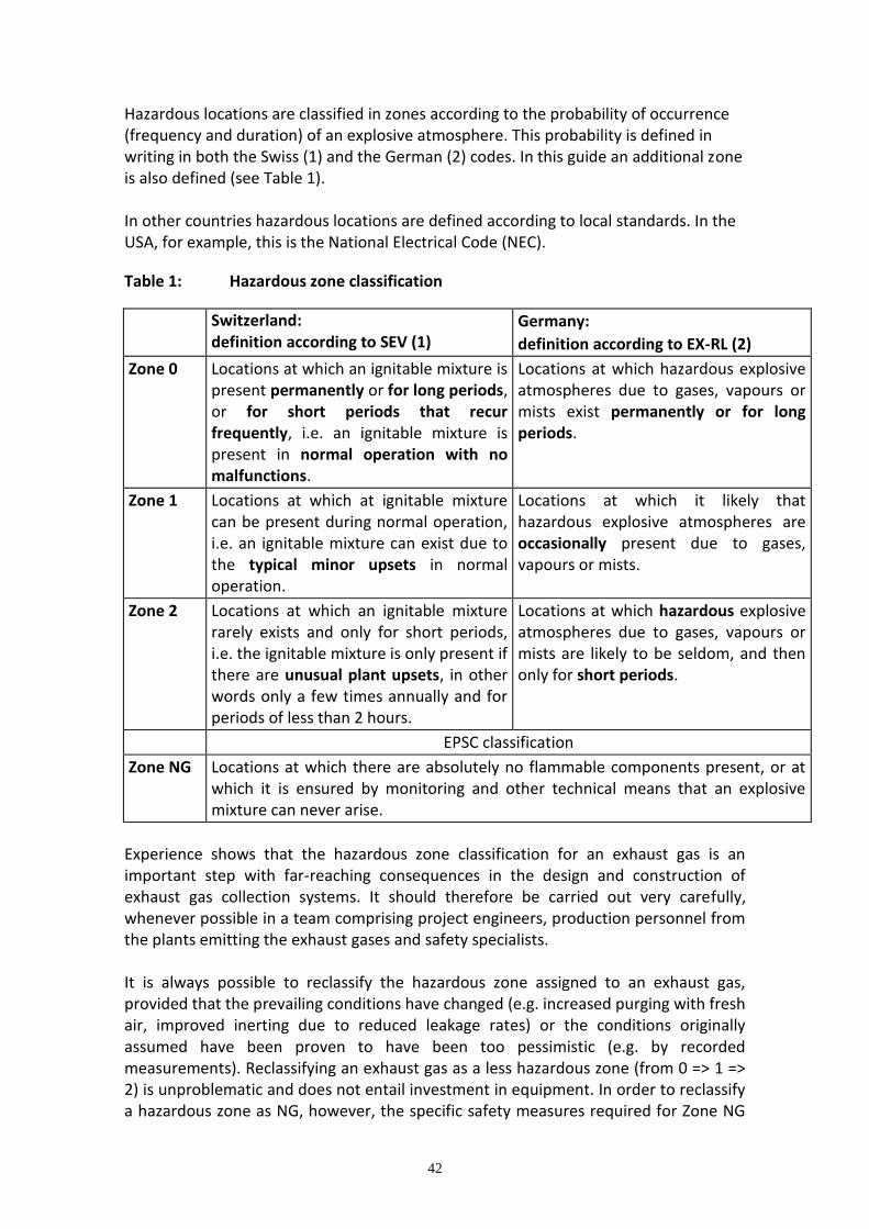
42
Hazardous locations are classified in zones according to the probability of occurrence (frequency and duration) of an explosive atmosphere. This probability is defined in writing in both the Swiss (1) and the German (2) codes. In this guide an additional zone is also defined (see Table 1). In other countries hazardous locations are defined according to local standards. In the USA, for example, this is the National Electrical Code (NEC).
Table 1: Hazardous zone classification
Switzerland: definition according to SEV (1)
Germany:
definition according to EX-RL (2)
Zone 0 Locations at which an ignitable mixture is present permanently or for long periods, or for short periods that recur frequently, i.e. an ignitable mixture is present in normal operation with no malfunctions.
Locations at which hazardous explosive atmospheres due to gases, vapours or mists exist permanently or for long periods.
Zone 1 Locations at which at ignitable mixture can be present during normal operation, i.e. an ignitable mixture can exist due to the typical minor upsets in normal operation.
Locations at which it likely that hazardous explosive atmospheres are occasionally present due to gases, vapours or mists.
Zone 2 Locations at which an ignitable mixture rarely exists and only for short periods, i.e. the ignitable mixture is only present if there are unusual plant upsets, in other words only a few times annually and for periods of less than 2 hours.
Locations at which hazardous explosive atmospheres due to gases, vapours or mists are likely to be seldom, and then only for short periods.
EPSC classification
Zone NG Locations at which there are absolutely no flammable components present, or at which it is ensured by monitoring and other technical means that an explosive mixture can never arise.
Experience shows that the hazardous zone classification for an exhaust gas is an important step with far-reaching consequences in the design and construction of exhaust gas collection systems. It should therefore be carried out very carefully, whenever possible in a team comprising project engineers, production personnel from the plants emitting the exhaust gases and safety specialists. It is always possible to reclassify the hazardous zone assigned to an exhaust gas, provided that the prevailing conditions have changed (e.g. increased purging with fresh air, improved inerting due to reduced leakage rates) or the conditions originally assumed have been proven to have been too pessimistic (e.g. by recorded measurements). Reclassifying an exhaust gas as a less hazardous zone (from 0 => 1 => 2) is unproblematic and does not entail investment in equipment. In order to reclassify a hazardous zone as NG, however, the specific safety measures required for Zone NG
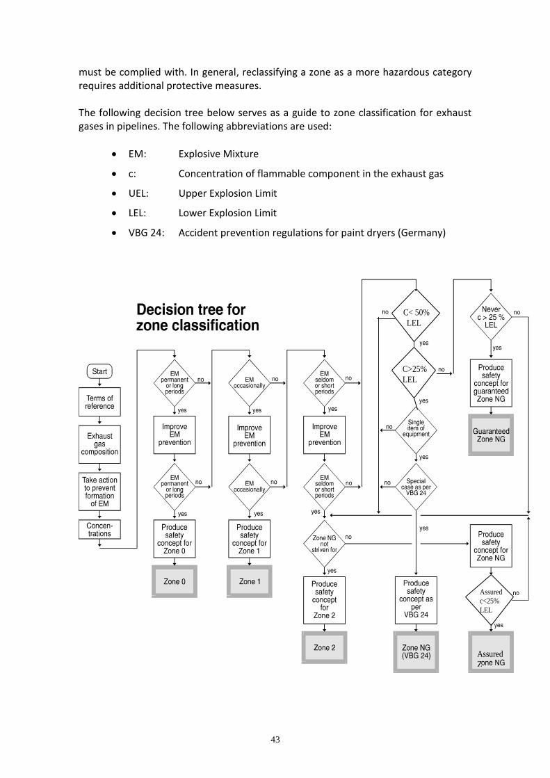
43
must be complied with. In general, reclassifying a zone as a more hazardous category requires additional protective measures. The following decision tree below serves as a guide to zone classification for exhaust gases in pipelines. The following abbreviations are used:
EM: Explosive Mixture
c: Concentration of flammable component in the exhaust gas
UEL: Upper Explosion Limit
LEL: Lower Explosion Limit
VBG 24: Accident prevention regulations for paint dryers (Germany)
Assured
Z
C< 50%
LEL
C>25%
LEL
Assured
c<25%
LEL
44
5.5 Zone NG (=Nicht Gefährlich / Not danGerous)
Guaranteed Zone NG: Due to either the media or the process, no exhaust gas stream with a concentration >25% LEL can form under any circumstances. Assured Zone NG: The exhaust gas stream is monitored and controlled by appropriate protective systems to a concentration of <25 % of LEL at the point of entry to Zone NG. Where Zone NG is dependent on the monitoring and control of flammable gases, vapours or dusts entering the zone ( Assured Zone NG) all the protective systems necessary to achieve this must be designed, installed, operated and maintained to meet the requirements of IEC 61508. It is also important that the requirements of the ATEX Directive and supplementary legislation and standards are fully met.
5.6 Assessing sources of Ignition
In addition to assessing and classifying the exhaust gas in terms of its ignitability, it is also crucially important when evaluating the overall hazard to determine and assess the possible sources of ignition. Classification is in the following four groups, depending on the probability of the potential source actually causing ignition:
Ignition source in normal operation
Ignition source during typical minor plant upsets
Ignition source during unusual plant upsets
No ignition source
Care must be taken that the risk assessment is carried out separately for every possible source of ignition in the system using the safety matrix shown later. To assist in making this assessment, the following section gives a breakdown of the most important equipment types and exhaust gas treatment processes. See appendix 7 for Classification of equipment and treatment processes according to their probability as ignition sources at the exhaust gas side.
5.7 Explosion Hazard Matrix
Safe design of exhaust gas systems means that both the probability of occurrence of ignition sources and the hazardous zone classification of the exhaust gas system must be taken into account. For this the zone in the exhaust gas system must be classified, and the probability of the electrical apparatus acting as a source of ignition must be determined.
45
The so-called safety matrix, in principle as described in TRbF 100, shows the combinations of hazardous zone and the explosion protection of the electrical apparatus. The 16 squares in the matrix specify the number of measures to be taken simultaneously and independently of each other to ensure that flame propagation is arrested, as well as showing further requirements for the design and manufacture of the equipment. The safety matrix shown overleaf differs from the TRbF 100 version by the addition of the Zone NG.
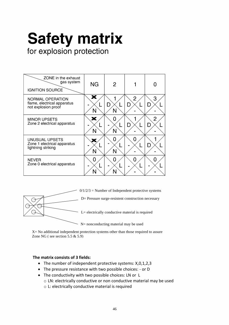
46
The matrix consists of 3 fields:
The number of independent protective systems: X,0,1,2,3
The pressure resistance with two possible choices: - or D
The conductivity with two possible choices: LN or L o LN: electrically conductive or non conductive material may be used o L: electrically conductive material is required
0/1/2/3 = Number of Independent protective systems
D= Pressure surge-resistent construction necessary
L= electrically conductive material is required
N= nonconducting material may be used
X= No additional independent protection systems other than those required to assure
Zone NG ( see section 5.5 & 5.9)
47
Examples for the use of the Explosion Hazard Matrix
1. Situation: A vessel, with an atmosphere declared as zone 1, should be evacuated with a vacuum pump designed for zone 2. Explosion Hazard Matrix - Row: zone 2 device - Column: zone 1 atmosphere - result: 1 / D / L Necessary measures 1: one explosion protection device (e.g. a flame arrester) is necessary before and behind the vacuum pump D: a pressure shock resistant design between the flame arresters is required L: the usage of electrically conductive pipes is required 1b. Alternative situation: A vessel, with an atmosphere declared as zone 1, is evacuated with a vacuum pump designed for zone 1. Explosion Hazard Matrix - Row: zone 1 device - Column: zone 1 atmosphere - result: 0 / - / L Necessary measures 0: no additional explosion protection device is necessary -: no pressure shock resistant design is required L: the usage of electrically conductive pipes is required 2. Situation: The waste gas stream declared as zone 1 is fed into a waste gas burner. Explosion Hazard Matrix - Row: continuous ignition source - Column: zone 1 atmosphere - result: 2 / D / L Necessary measures 2: two independent explosion protection devices (e.g. a detonation arrester and a flow controlled aperture injection) are necessary D: a pressure shock resistant design is required L: the usage of electrically conductive pipes is required
48
5.8 Blowers, Compressors and Fans
Blowers used to handle explosive gas mixtures with Zone 1 or 2 classification must be constructed to an explosion-proof design. This involves increased demands on materials, components, vibration characteristics and the clearance between the impeller and the housing. Other design features prevent an increase of temperature at the shaft bearings and seal and in the gas being handled. Since no blowers are in existence that would satisfy the requirements for handling Zone 0 explosive mixtures, models authorised for use in Zone 1 must be used and isolated by means of flame arresters. Similar requirements are made in the design of blowers for handling flammable dusts. Detailed information and references to further documentation are given in reference 12. They must be specified when ordering blowers. Other design features to prevent the creation of an ignition source at the shaft bearings or seals in the case of failure may also be required. All equipment for these zones must meet the requirements of the ATEX directive.
5.9 Piping Systems
All piping systems, from the source of the exhaust gas through to the thermal treatment unit, must be constructed according to the specifications in the safety
matrix. The piping must whenever possible be installed with a slope of 2 %, avoiding low points where moisture and dirt can accumulate. In some cases shown in the safety matrix the piping systems conveying Zone 0, 1 or 2 exhaust gas streams, the pipe itself plus the gaskets, valves and other in-line components must be pressure surge-resistant. The requirements for complying with pressure surge resistance are as follows:
a. For nominal pipe sizes up to DN 200 the design pressure must be at least 10 bar, from DN 250 upwards at least 16 bar.
b. Bends from DN 250 upwards must have a bending radius of at least 1.5 D. Mitred bends are not permissible.
c. Abrupt changes of cross section must be avoided. Valves with a full bore must therefore be fitted whenever possible - ball valves up to DN 80 and butterfly valves or slide valves from DN 100 upwards.
Because of electrostatic problems with piping installed in Zones 0, 1 or 2 the following points must be taken into account when selecting materials:
49
a) Metallic materials of construction Provided that adequate chemical resistance is offered, there are no particular restrictions on the use of metallic piping materials. b) Plastics
The use of piping in electro-statically conducting plastics is generally possible for all zones. Particular care must be taken, however, that non-conducting plastics are not used inadvertently when installing electro-statically conducting plastic piping (separate ordering and storage, unambiguous labelling with corresponding documentation to be specified). Non-conducting plastics are restricted to Zones 2 and NG. The basic rule is that the suitability of a plastic must be demonstrated for each individual application (electrostatic conductivity, pressure surge resistance and chemical resistance). The
earth leakage resistance must 106 . This must be verified before start-up.
5.10 Application to Existing Vent and Relief Systems
The concepts defined in this note may be applied to existing vent and relief systems. A full understanding of the system of the system should be established by
Collection of data
Understanding of the material entering the system
Pressure and temperature limits
It is strongly recommended that all stages defined in section 5 of this note are implemented for existing systems, including thorough and systematic Hazard Identification by HAZOP or other procedures. The information obtained should be collated and may be used to meet the requirements of the ATEX directive where this applies. See section 7 for changes and modifications to the system.
50
References
1. HAZOP: Guidelines to best practice for the process and chemical industries, F
Crawley, M L Preston & B J Tyler, EPSC 2000 2. Ciba Specialty Chemicals, “Explosion Protection in Exhaust Gas Collection
Systems for Centralised Treatment”, Techn. Guidance Note 37.50100, Ed. November 1993
3. ICI Fire and Explosion Hazards Guide 4. Hazard Identification methods, F Crawley & B J Tyler, EPSC 2003 5. HAZOP and HAZAN, Trevor Kletz, 4th edition, , IChemE 1999 6. Risk Assessment in the Process Industries, Robin Pitbaldo and Robin Turney, 2nd
edition, IChemE 1996 7. SEV3301: Codes of practice for assessing the explosion risk in plants with
hazardous zones, Swiss Electricians Association 8. EX-RL: Explosion protection guidelines of the German chemical industry
employer's liability insurance associations, Guideline No. 11,ZH1/10, September 1990 edition
9. TRbF 100: Codes of practice for combustible liquids, September 1992 edition 10. TD N 283: Assignment of pipe classes for flowing media 11. TD R 349: Flame arresters on vessels 12. VDMA 24169: Explosion protection design of fans, German Mechanical
Engineering Association 13. VBG 24 Paint dryers, German Accident Prevention Regulations
51
6. Protective Measures
In this section consideration is given to the devices which can be installed with a vent or relief system in order to provide explosion protection and prevent flame propagation.
6.1 Hydraulic (Liquid) Seals
In the petrochemical industry, process/emergency discharges of flammable gas or vapour are usually passed into a liquid (water) seal before going to the flare/vent stack, this item separates the upstream gas system from the atmosphere and avoids air infiltration. In flare systems the liquid seal can be downstream from the liquid separator (K-O drum) or incorporated in the same vessel, but this last solution is not preferred. It is possible to design hydraulic seals which will extinguish a flame and avoid flash-back propagation by means of the quench effect of the water content. Usually a baffle maintains the normal level water and the gas/vapour inlet is submerged into the liquid, this guarantees a positive pressure in the header ensuring that any accidental leak will result in a gas discharge into the atmosphere and not let air infiltration inside the system. Drum and pipe dimensions (min. ratio dleg/Ddrum = 1/3) are sized with special considerations (see the sketch attached for more details) in order to:
prevent liquid carrying (and ensure gas disengagement) during the discharge
avoid liquid push-back in the header (in case of vacuum conditions in the upstream section)
avoid gas breakthrough in the water outlet siphon
assure an immediate replacement of any loss of liquid Water seals may be equipped with measuring instruments to monitor the operating data such as: gas/liquid temperatures, gas flow-rate, liquid level depth, etc. If improperly designed, an undesirable operating characteristic of water seals is the creation of surging flow with violent flow and pressure pulsations both upstream and downstream. A sufficient immersion depth is necessary to prevent ignition breakthrough in case of long lasting fire or deflagration downstream. However many authors have some doubts about the ability of liquid seals to provide an effective barrier to flame propagation even if where they break the gas stream into discrete small burning bubbles. Where internal explosion is considered possible it is important that a sufficient quantity of water is present in the drum and in the vertical inlet pipe so that, in the event of flash-back with deflagration, it can offer a degree of resistance to the
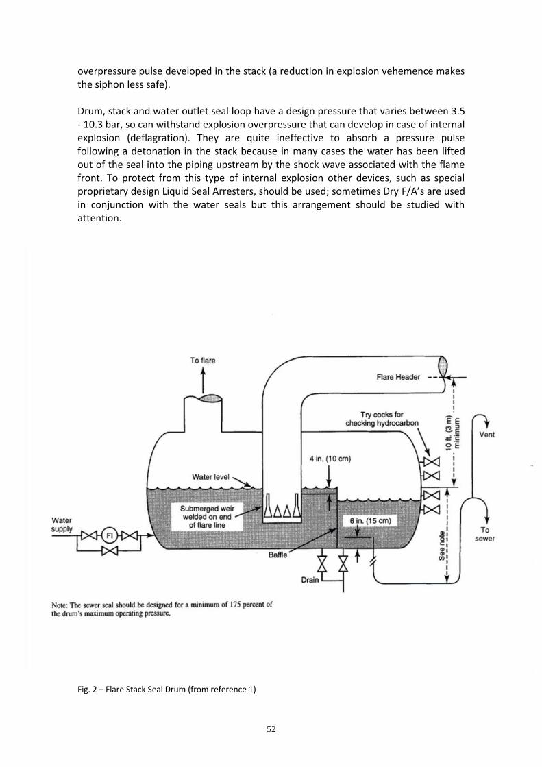
52
overpressure pulse developed in the stack (a reduction in explosion vehemence makes the siphon less safe). Drum, stack and water outlet seal loop have a design pressure that varies between 3.5 - 10.3 bar, so can withstand explosion overpressure that can develop in case of internal explosion (deflagration). They are quite ineffective to absorb a pressure pulse following a detonation in the stack because in many cases the water has been lifted out of the seal into the piping upstream by the shock wave associated with the flame front. To protect from this type of internal explosion other devices, such as special proprietary design Liquid Seal Arresters, should be used; sometimes Dry F/A’s are used in conjunction with the water seals but this arrangement should be studied with attention.
Fig. 2 – Flare Stack Seal Drum (from reference 1)
53
6.2 Dry Flame Arresters
Dry flame arresters are static devices. Their main mechanism of action is based on the flame quenching process and heat removal determined by the flame passage in a narrow gap. The characteristic parameters are the gap width and gap length which depend on the flammable mixture classification and can be calculated using specific relations, see reference 8. For this reason they are formed by an internal arrester element (called matrix) obtained by assembling wire gauze or corrugated metal ribbon in different ways to get multiple small channels. The main properties of the flame arresters are:
high free cross sectional area available for the flow passage
low resistance
high capacity to absorb the heat of the flame
ability to withstand thermal and mechanical shocks as in case of violent explosion
Depending on the hazardous effect due to the combustion process and the part of the plant to be protected they are divided into:
Explosion (Deflagration) F/A
Detonation F/A
Endurance Burning F/A that can be installed at the end of the pipe (vent outlet) to prevent the transmission of the flame from the outside into the equipment or in (-line) pipelines to prevent the propagation of the flame into section of the plant if deflagration and/or detonation occur in the pipe. The use of Flame Arresters in flare systems are quite limited due to the strict characteristics of gas (non corrosive and free from liquid), possibility of obstruction, etc. The narrow passages may be liable to blockages and great care is necessary in using flare traps where dusts may be present or vapours which can polymerise. The European standard that specifies the requirements and application of flame arresters and establish the criteria for the construction, testing and marking is the EN 12847 (for more information see reference 8, 9 & 11).
6.3 Explosion suppression
Explosion suppression systems are devices that prevent pressure build-up in vessel/pipes by quenching the flame in the initial development phase of the explosion.
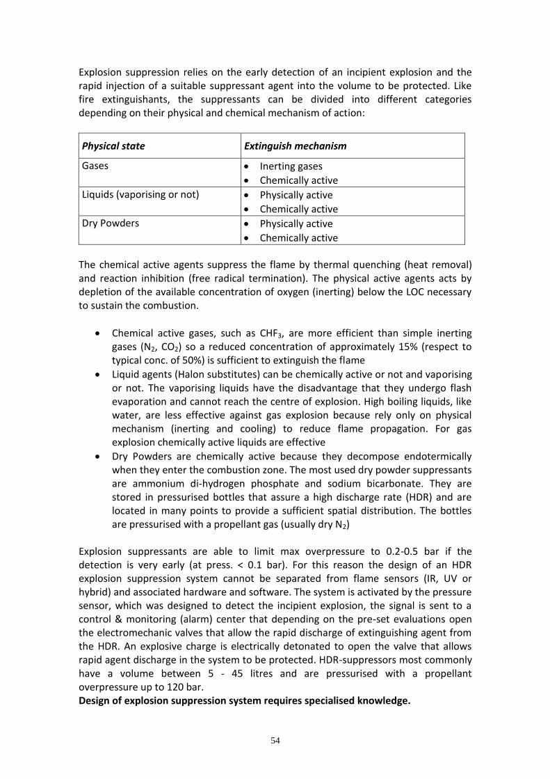
54
Explosion suppression relies on the early detection of an incipient explosion and the rapid injection of a suitable suppressant agent into the volume to be protected. Like fire extinguishants, the suppressants can be divided into different categories depending on their physical and chemical mechanism of action:
Physical state Extinguish mechanism
Gases Inerting gases
Chemically active
Liquids (vaporising or not) Physically active
Chemically active
Dry Powders Physically active
Chemically active
The chemical active agents suppress the flame by thermal quenching (heat removal) and reaction inhibition (free radical termination). The physical active agents acts by depletion of the available concentration of oxygen (inerting) below the LOC necessary to sustain the combustion.
Chemical active gases, such as CHF3, are more efficient than simple inerting gases (N2, CO2) so a reduced concentration of approximately 15% (respect to typical conc. of 50%) is sufficient to extinguish the flame
Liquid agents (Halon substitutes) can be chemically active or not and vaporising or not. The vaporising liquids have the disadvantage that they undergo flash evaporation and cannot reach the centre of explosion. High boiling liquids, like water, are less effective against gas explosion because rely only on physical mechanism (inerting and cooling) to reduce flame propagation. For gas explosion chemically active liquids are effective
Dry Powders are chemically active because they decompose endotermically when they enter the combustion zone. The most used dry powder suppressants are ammonium di-hydrogen phosphate and sodium bicarbonate. They are stored in pressurised bottles that assure a high discharge rate (HDR) and are located in many points to provide a sufficient spatial distribution. The bottles are pressurised with a propellant gas (usually dry N2)
Explosion suppressants are able to limit max overpressure to 0.2-0.5 bar if the detection is very early (at press. < 0.1 bar). For this reason the design of an HDR explosion suppression system cannot be separated from flame sensors (IR, UV or hybrid) and associated hardware and software. The system is activated by the pressure sensor, which was designed to detect the incipient explosion, the signal is sent to a control & monitoring (alarm) center that depending on the pre-set evaluations open the electromechanic valves that allow the rapid discharge of extinguishing agent from the HDR. An explosive charge is electrically detonated to open the valve that allows rapid agent discharge in the system to be protected. HDR-suppressors most commonly have a volume between 5 - 45 litres and are pressurised with a propellant overpressure up to 120 bar. Design of explosion suppression system requires specialised knowledge.
55
6.4 Explosion Isolation
Another method to avoid explosion propagation, especially through a pipeline, is isolation by means of an appropriate designed mechanical barrier; these are fast-acting valves mounted laterally to the pipe (Slide) or internally (Flap or Float) with different mechanisms of actuation: self-actuated or externally driven- see reference 7 for more information.
References
1. API-RP-521, “Guide for Pressure-Relieving and Depressuring Systems” 4th Ed., March 1997
2. D. Shore, “Making the flare safe”, J. Loss Prev. Process Ind., Vol. 9. No. 6, pp. 363-381, 1996
3. R. Reed, “Design and Operation of Flare Systems”, Chem. Eng. Progress (Vol. 64. No. 6), 1968
4. R. Garland & M.O. Malcolm, “Evaluating Vent Manifold Inerting Requirements: Flash Point Modelling for Organic Acid-Water Mixtures”, Process Safety Progress (Vol.21, No. 3), Sept. 2002, p. 254
5. TCD Research Project (2001)
6. Ciba Specialty Chemicals, “Explosion Protection in Exhaust Gas Collection Systems for Centralised Treatment”, Technical Guidance Note 37.50100, Ed. November 1993
7. S.S. Grossel, “Deflagration and Detonation Flame Arresters”, CCPS Book, 2002
8. BS EN 12847, “Flame Arresters - performance requirements, test methods and limit for use”, 2001
9. NFPA-69, Standard on “Explosion Prevention Systems”, 1997 Ed.
10. Flame Arrestors HS(G)158-Preventing the spread of fires and explosions in equipment that contains flammable Gases and Vapours, 1996
11. CCPS. 1998 Guidelines for Pressure Relief and Effluent Handling Systems AIChE/CCPS, New York, NY.
12. API Standard 537, 2003, Flare Details for General Refinery and Petrochemical Service
13. T. Ennis. 2003, Safety & Design Aspects of Vent Collection & Destruction Systems Proceedings of the AIChE 2003 Process Plant Safety Symposium

56
7. Management of Change (MOC)
For a chemical manufacturing facility to survive in a dynamic industry, it must be able to quickly adapt to changing conditions such as increasing production, reducing operating costs, improving employee and process safety, accommodating technical innovation, compensating for unavailable equipment and/or reducing pollution potentials. The chemical plant must also have a method to review temporary repairs, temporary connections or deviations from standard operations. It is essential that chemical plant modifications are properly engineered and implemented to avoid actual and potential problems. The changes carried-out during the life-time of a facility may well involve the vent and relief systems. Any changes to these systems need to be reviewed critically. Incidents reveal that a failure to give sufficient emphasis & attention to the safety review of such systems can result in the introduction of new hazards and increases in the risks. We therefore recommend the following approach in case of changes concerning the waste gas system:
7.1 When do we call it a change?
The basic principle is as follows: Any technical activity except the replacement in kind of construction parts is considered a change. Example of a replacement in kind: replacing a fan by a fan of the same type with the same performance. Example of a change: replacing the fan by a similar type of fan with speed control or by a fan with a different capacity. Example of an administrative change: change of the cleaning cycle, changing the accountability for specific pipe sections. Additional examples of changes:
The introduction of a new material or the elimination of an existing material.
Changes in composition within the design limits will not need to be considered as a change
57
7.2 What does it take to handle the change, how do we have to manage it?
The response to this question is: You have to handle it on the basis of a systematic “management of change”. Prior to tackling the technical issues you have to define the organizational procedure to handle the change. You have to allocate responsibility, tasks and competencies. This procedure defines the framework of the technical work which needs to be done. If you do not define a framework for the technical work you will cause unnecessary confusion and a lack of communication. The technical work will be made more difficult. To prevent this from happening you have to develop a framework, the ‘management of change’. This system may be compared to the quality management systems where you set up a system first and fill it with content later on. Important is that a MOC procedure exists and is implemented.
7.3 Where does the technical work start?
It starts with examining the data of the existing system prior to the change. As waste gas systems are often put in as a ‘retro-fit’, you have to update the following information:
volume flows
ingredients
P&I diagrams
materials, seals, fittings
inspecting the pipes
checking the state of the pipe (appearance, interior coatings, ......)
updating the data of the party feeding the pipe
updating the drainage areas
updating organizational accountabilities
updating cost centres ……
7.4 The next step before the implementation of the change is as follows:
A written description of the project and communication with everybody concerned in line with the management system. This process of communication may trigger further changes which do not make life easier but it is a good thing if the requirements become visible now instead of appearing at a later stage.
58
7.5 The idea is taking shape
Once you gathered all the requirements, the whole project has turned into a package of change. This package of change is now available in writing and everybody knows what is going on.
7.6 The safety check
No matter how perfect the MOC systems are, they will never replace the technical work. It is important that those making the assessment have the necessary expertise and experience. (Incident 1 provides an example of where this was not so). In order to make sure that the required safety check is done with reasonable effort we recommend using a checklist: General issues
Do you have to update the safety concepts? (concepts of waste gas systems, disposal systems, related plants)
What will be the impact of the waste gas ingredients?
Are undesired reactions in the waste gas system possible?
Is the disposal system adequate at all?
Is the material used a long-lasting material? Watch out if hoses are involved.
May the change cause reactive deposits in the waste gas pipes?
What impact does the change have on the way the system is cleaned?
Can the change possibly cause a self-ignition anywhere?
Did you check the impact of the change on the rest of the plant? (e.g. backflow of substances into the equipment, thus causing risks).
Will the maximum levels of excessive or negative pressure be exceeded in the system or in the equipment connected to the system?
Does the change cause the risk of flooding the waste gas system with liquid product?
Did you make sure that the maximum temperature will not be exceeded during start-up, shut-down and normal operation? (Be aware of pipes made of plastic)
Can waste gas spill at a certain location and jeopardize the workers?
Is there a risk of static charging, have adequate measures been taken to prevent this from happening?
Let’s assume your system is made of metal. May deposits cause an electrically insulating layer which causes electrostatic charging in the system?
59
Instrumentation:
Do you need new safety-relevant measuring points or alarms, can you do without any of those used so far?
Documentation and training
Did you update the operational procedure and the P&I diagrams?
Did you discuss the change with everybody concerned and did you document this?
Do you have to update the risk assessment? Emissions:
Did you record and consider all the new or changed sources of emission?
Do you have to update the emission monitoring system?
Do you have to update your notifications to the authorities?
Impact on waste gas
How does the change impact the composition of the waste gas?
Is there a risk of the development of hazardous fumes?
Do you have an adequate waste gas treatment plant?
Do you have an adequate waste gas network or will there be long-term problems such as corrosion, erosion, deposits...?
Mistakes and failures:
What can happen in case of an operating error?
What would be the worst mistake which could happen due to the failure of one or several measuring or control devices?
What would happen in case of a power failure? For major changes or high hazard processes it is important to ask the question as to whether more formal Hazard Identification such as HAZOP should be carried out.
7.7 Record the safety check
You have to document the check. The record will be of value if further changes are required. You will be asked for the documentation in case of an incident. The list enables you to use the computer for this documentation, based on the rules applying in the respective plant.
7.8 Conclusion
Handling changes of the waste gas system seems to be very complex. One incident, however, will require much more time and effort in terms of follow-up.
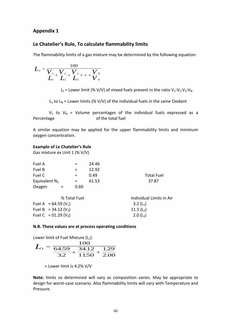
60
Appendix 1 Le Chatelier’s Rule, To calculate flammability limits
The flammability limits of a gas mixture may be determined by the following equation:
L
N
N
LVL
VL
VL
VV
100
1
1
2
2
3
3
LL = Lower limit (% V/V) of mixed fuels present in the ratio V1:V2:V3:VN
L1 to LN = Lower limits (% V/V) of the individual fuels in the same Oxidant V1 to VN = Volume percentages of the individual fuels expressed as a Percentage of the total fuel A similar equation may be applied for the upper flammability limits and minimum oxygen concentration. Example of Le Chatelier’s Rule Gas mixture ex Unit 1 (% V/V) Fuel A = 24.46 Fuel B = 12.92 Fuel C = 0.49 Total Fuel Equivalent N2 = 61.53 37.87 Oxygen = 0.60 % Total Fuel Individual Limits in Air Fuel A = 64.59 (V1) 3.2 (L1) Fuel B = 34.12 (V2) 11.5 (L2) Fuel C = 01.29 (V3) 2.0 (L3) N.B. These values are at process operating conditions
Lower limit of Fuel Mixture (LL):
LL
100
64 59
32
3412
1150
129
2 00
.
.
.
.
.
.
= Lower limit is 4.2% V/V Note: limits so determined will vary as composition varies. May be appropriate to design for worst-case scenario. Also flammability limits will vary with Temperature and Pressure.
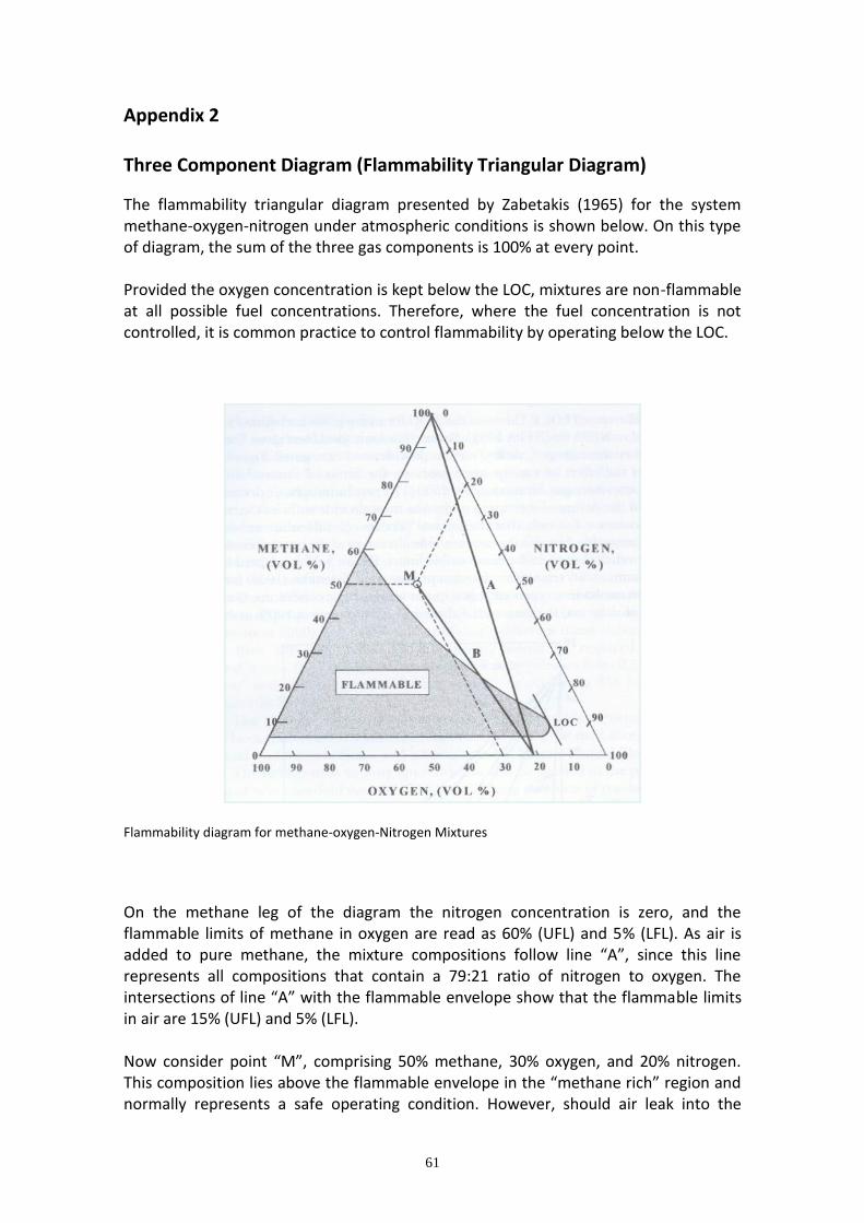
61
Appendix 2 Three Component Diagram (Flammability Triangular Diagram)
The flammability triangular diagram presented by Zabetakis (1965) for the system methane-oxygen-nitrogen under atmospheric conditions is shown below. On this type of diagram, the sum of the three gas components is 100% at every point. Provided the oxygen concentration is kept below the LOC, mixtures are non-flammable at all possible fuel concentrations. Therefore, where the fuel concentration is not controlled, it is common practice to control flammability by operating below the LOC.
Flammability diagram for methane-oxygen-Nitrogen Mixtures
On the methane leg of the diagram the nitrogen concentration is zero, and the flammable limits of methane in oxygen are read as 60% (UFL) and 5% (LFL). As air is added to pure methane, the mixture compositions follow line “A”, since this line represents all compositions that contain a 79:21 ratio of nitrogen to oxygen. The intersections of line “A” with the flammable envelope show that the flammable limits in air are 15% (UFL) and 5% (LFL). Now consider point “M”, comprising 50% methane, 30% oxygen, and 20% nitrogen. This composition lies above the flammable envelope in the “methane rich” region and normally represents a safe operating condition. However, should air leak into the

62
system, the resulting compositions follow line “B” which passes through the flammable envelope. Given the possibility of an air leak, available strategies are (1) operate below the LFL in air, or (2) operate so that there is insufficient oxygen to support a flame at the given concentration of fuel. If we look at option (2) or “oxidant concentration reduction” , there are two variants of this method. As shown in the diagram above the LOC is 12% oxygen at standard conditions. Provided the oxygen concentration is kept below the LOC, mixtures are non-flammable at all possible fuel concentrations. Therefore, where the fuel concentration is not controlled, it is common practice to control flammability by operating below the LOC.
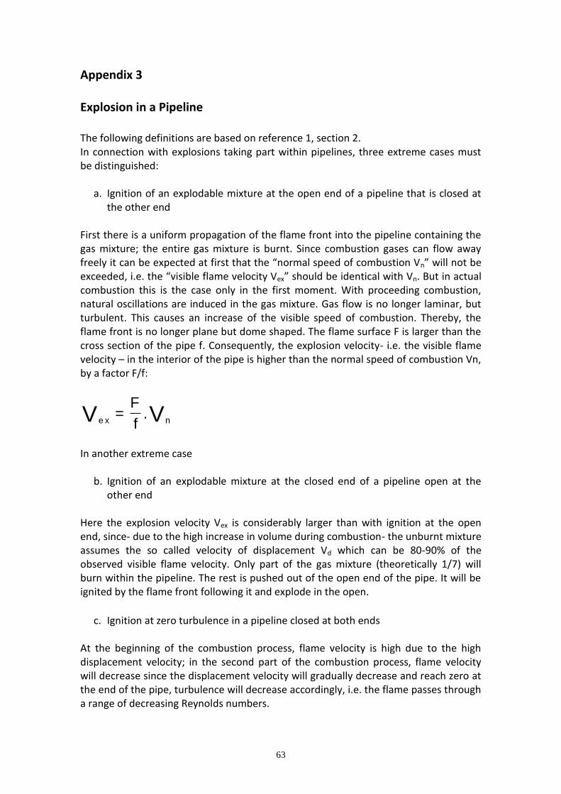
63
Appendix 3 Explosion in a Pipeline The following definitions are based on reference 1, section 2. In connection with explosions taking part within pipelines, three extreme cases must be distinguished:
a. Ignition of an explodable mixture at the open end of a pipeline that is closed at the other end
First there is a uniform propagation of the flame front into the pipeline containing the gas mixture; the entire gas mixture is burnt. Since combustion gases can flow away freely it can be expected at first that the “normal speed of combustion Vn” will not be exceeded, i.e. the “visible flame velocity Vex” should be identical with Vn. But in actual combustion this is the case only in the first moment. With proceeding combustion, natural oscillations are induced in the gas mixture. Gas flow is no longer laminar, but turbulent. This causes an increase of the visible speed of combustion. Thereby, the flame front is no longer plane but dome shaped. The flame surface F is larger than the cross section of the pipe f. Consequently, the explosion velocity- i.e. the visible flame velocity – in the interior of the pipe is higher than the normal speed of combustion Vn, by a factor F/f:
e x nV VF
f= .
In another extreme case
b. Ignition of an explodable mixture at the closed end of a pipeline open at the other end
Here the explosion velocity Vex is considerably larger than with ignition at the open end, since- due to the high increase in volume during combustion- the unburnt mixture assumes the so called velocity of displacement Vd which can be 80-90% of the observed visible flame velocity. Only part of the gas mixture (theoretically 1/7) will burn within the pipeline. The rest is pushed out of the open end of the pipe. It will be ignited by the flame front following it and explode in the open.
c. Ignition at zero turbulence in a pipeline closed at both ends
At the beginning of the combustion process, flame velocity is high due to the high displacement velocity; in the second part of the combustion process, flame velocity will decrease since the displacement velocity will gradually decrease and reach zero at the end of the pipe, turbulence will decrease accordingly, i.e. the flame passes through a range of decreasing Reynolds numbers.
64
However, if the gas/air mixtures in the closed pipeline are turbulent, and if the ignition at one end is by flame jet, then this “braking action” is no longer effective, and all flammable gases (methane, propane, hydrogen) will reach the stage of quasi-detonation or detonation within a length of 30m, although the distance needed for acceleration to very high combustion velocities is longer than in pipelines open at one end.
Since in a closed pipeline there is no expulsion of unburnt mixture, the total quantity of flammable gas enclosed in the line takes part in the combustion reaction. Consequently- at equal explosion velocity- explosion pressures will be several bars higher than in pipelines open at one end. Extraordinary high pressures are observed when a detonation runs against a solid wall- e.g. against a blind flange at the end of a pipeline. Gases are decelerated to zero and the shock wave is reflected. The pressure acting on the end flange is approx. three times higher than the pressure in the gas behind the detonation- see reference 1 for more information.
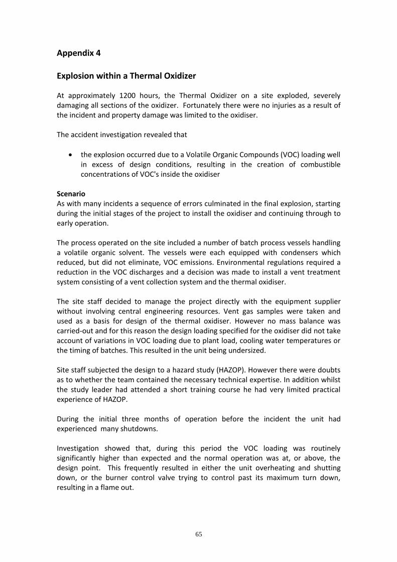
65
Appendix 4 Explosion within a Thermal Oxidizer
At approximately 1200 hours, the Thermal Oxidizer on a site exploded, severely damaging all sections of the oxidizer. Fortunately there were no injuries as a result of the incident and property damage was limited to the oxidiser. The accident investigation revealed that
the explosion occurred due to a Volatile Organic Compounds (VOC) loading well in excess of design conditions, resulting in the creation of combustible concentrations of VOC's inside the oxidiser
Scenario As with many incidents a sequence of errors culminated in the final explosion, starting during the initial stages of the project to install the oxidiser and continuing through to early operation. The process operated on the site included a number of batch process vessels handling a volatile organic solvent. The vessels were each equipped with condensers which reduced, but did not eliminate, VOC emissions. Environmental regulations required a reduction in the VOC discharges and a decision was made to install a vent treatment system consisting of a vent collection system and the thermal oxidiser. The site staff decided to manage the project directly with the equipment supplier without involving central engineering resources. Vent gas samples were taken and used as a basis for design of the thermal oxidiser. However no mass balance was carried-out and for this reason the design loading specified for the oxidiser did not take account of variations in VOC loading due to plant load, cooling water temperatures or the timing of batches. This resulted in the unit being undersized. Site staff subjected the design to a hazard study (HAZOP). However there were doubts as to whether the team contained the necessary technical expertise. In addition whilst the study leader had attended a short training course he had very limited practical experience of HAZOP. During the initial three months of operation before the incident the unit had experienced many shutdowns.
Investigation showed that, during this period the VOC loading was routinely significantly higher than expected and the normal operation was at, or above, the design point. This frequently resulted in either the unit overheating and shutting down, or the burner control valve trying to control past its maximum turn down, resulting in a flame out.
66
A number of site personnel also recalled vividly that prior to the incident the safety trips shut down the combustion air, exhaust air and pilot air blower. The investigation team concluded that this probably was the mode of operation for some period of time. However, this was not consistent with the electrical schematics. It was further concluded that the contractor had probably rewired the blower control circuits to conform to the electrical schematics shortly before the incident. The accident happened at a time of high load on a hot summer’s day when VOC losses from the process would have been at a high level. Shortly before the incident, during the course of natural cycling of VOC loading, the temperature in the oxidiser began to increase. To compensate the burner control valve closed to the point where the flame became unstable and flamed out. The ‘flame-out’ relay shut down the fuel supply and the high temperature trip, which had slower response time than the temperature controller, was reached within moments. The blowers continued to run. The oxidiser temperature dropped more slowly than on previous occasions and the investigation team hypothesized that
VOC loading was high enough to maintain some secondary burning for some period of time
As the VOC loading cycled back below the LEL, all combustion stopped
Before the unit cooled, the VOC loading increased again above the LEL
As the vapours passed through the oxidiser, they were heated to at least 704°F (373°C) resulting in auto ignition
A blow-off panel fitted to the oxidiser failed to provide protection.
Direct Causes The circumstances which resulted in the explosion were those things which caused or allowed the oxidizer to fill with flammable concentrations of vapours.
When the burner shutdown on ‘flame out’ or high temperature, the "A" control valve remained open, allowing VOC's to continue to flow through the oxidiser, with a VOC loading above the lower explosive limit
Root Causes
The project was designed, constructed and commissioned without any written process description. Therefore the operators design intent was not consistent with the system furnished by the oxidiser contractor
There was no mass balance or process estimate of the VOC loading. Therefore, there was no basis for evaluating the validity of the emissions sampling used as the basis of the design
The possibility of high VOC loading was not identified as a hazard during the HAZOP study
The lack of understanding by the operator resulted in the design of an inappropriate safety interlock system which did not protect the unit in cases of high VOC loading
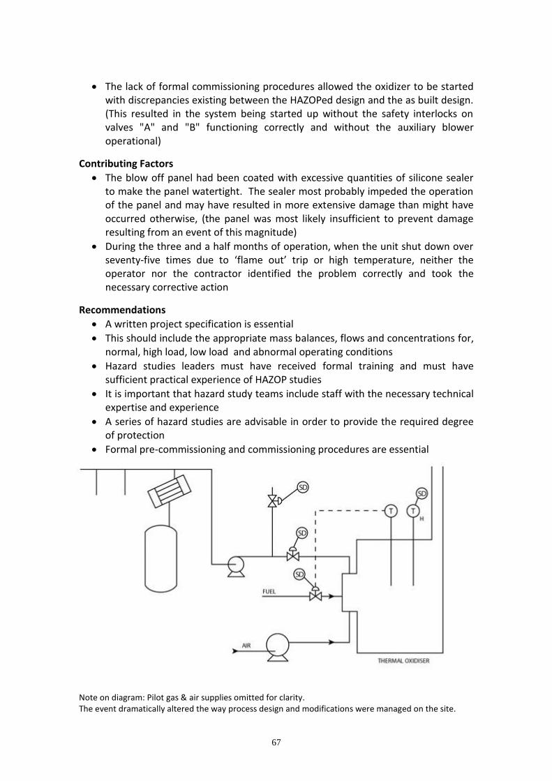
67
The lack of formal commissioning procedures allowed the oxidizer to be started with discrepancies existing between the HAZOPed design and the as built design. (This resulted in the system being started up without the safety interlocks on valves "A" and "B" functioning correctly and without the auxiliary blower operational)
Contributing Factors
The blow off panel had been coated with excessive quantities of silicone sealer to make the panel watertight. The sealer most probably impeded the operation of the panel and may have resulted in more extensive damage than might have occurred otherwise, (the panel was most likely insufficient to prevent damage resulting from an event of this magnitude)
During the three and a half months of operation, when the unit shut down over seventy-five times due to ‘flame out’ trip or high temperature, neither the operator nor the contractor identified the problem correctly and took the necessary corrective action
Recommendations
A written project specification is essential
This should include the appropriate mass balances, flows and concentrations for, normal, high load, low load and abnormal operating conditions
Hazard studies leaders must have received formal training and must have sufficient practical experience of HAZOP studies
It is important that hazard study teams include staff with the necessary technical expertise and experience
A series of hazard studies are advisable in order to provide the required degree of protection
Formal pre-commissioning and commissioning procedures are essential
Note on diagram: Pilot gas & air supplies omitted for clarity. The event dramatically altered the way process design and modifications were managed on the site.

68
Appendix 5
EPSC Inherent Safety Statement
It is good practice to apply Inherent Safety principles when developing a new process or plant – or when considering changes to existing ones. At the heart of the inherent safety concept is the desire to step back from the prevailing tendency to design complex safety systems to control the hazards of proposed processes, and fundamentally review the process in terms of:
can we use a safer route to manufacture the product which involves less hazardous raw materials and intermediates?
can the quantity of hazardous materials involved be reduced, and can the physical conditions in which they are processed be moderated?
can the equipment used to perform the various unit operations of the process be selected to optimise their safety and reliability?
Applying Inherent Safety principles can reduce the hazards to people’s safety, the hazards to their health, and the hazards to the environment. In addition a positive business case can often be made for designing an inherently safer plant. Inventory levels may be minimised, reducing the capital held up in feedstock, intermediate and product storage. A simpler plant may be more reliable and need less maintenance. Waste minimisation can reduce both production costs and environmental impact. Application of Inherent Safety within an organisation can be most effective if:
it is supported by a ‘champion’ at a senior level within the company
staff from a broad range of disciplines, including chemists, process engineers, control engineers, mechanical engineers and designers are provided with suitable training and made aware of the principles of Inherent Safety
it is applied from the very earliest stages of process and project development
reviews are carried out at set points during a project to identify how well the principles of Inherent Safety have been applied
teams and individuals that are successful in the application of Inherent Safety are recognised and rewarded by the company
The greatest value may be obtained by using an integrated approach to improve the safety, occupational health and environmental impact of a process. The common Inherent Safety guidewords, as outlined below, can be applied throughout the design process to help those involved consider alternatives.
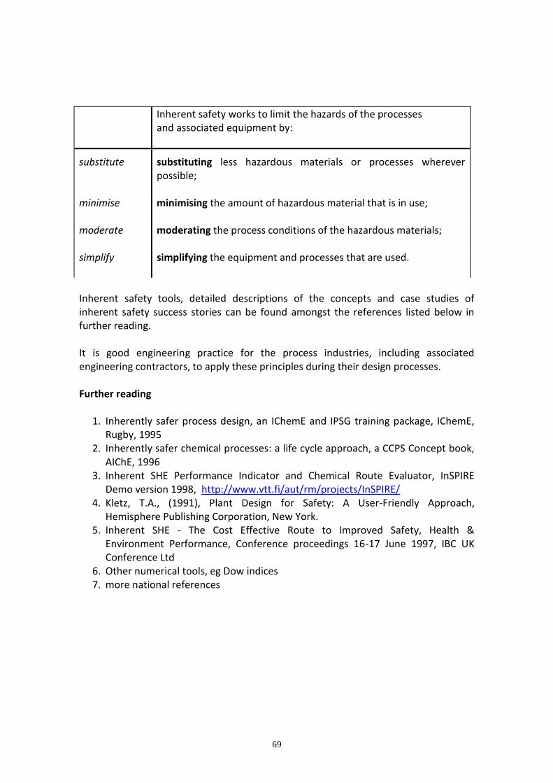
69
Inherent safety works to limit the hazards of the processes and associated equipment by:
substitute
substituting less hazardous materials or processes wherever possible;
minimise
minimising the amount of hazardous material that is in use;
moderate
moderating the process conditions of the hazardous materials;
simplify
simplifying the equipment and processes that are used.
Inherent safety tools, detailed descriptions of the concepts and case studies of inherent safety success stories can be found amongst the references listed below in further reading. It is good engineering practice for the process industries, including associated engineering contractors, to apply these principles during their design processes. Further reading
1. Inherently safer process design, an IChemE and IPSG training package, IChemE, Rugby, 1995
2. Inherently safer chemical processes: a life cycle approach, a CCPS Concept book, AIChE, 1996
3. Inherent SHE Performance Indicator and Chemical Route Evaluator, InSPIRE Demo version 1998, http://www.vtt.fi/aut/rm/projects/InSPIRE/
4. Kletz, T.A., (1991), Plant Design for Safety: A User-Friendly Approach, Hemisphere Publishing Corporation, New York.
5. Inherent SHE - The Cost Effective Route to Improved Safety, Health & Environment Performance, Conference proceedings 16-17 June 1997, IBC UK Conference Ltd
6. Other numerical tools, eg Dow indices 7. more national references
70
Appendix 6 Chemical Interaction Performa
Procedure
a. List all the materials on the proforma under “Chemical or Group of Chemicals”. Be as descriptive as possible, i.e. use the recognised chemical name or names and include any trade names and abbreviations or product code name/numbers. Materials of construction should be listed in the lower section of the proforma: these include materials in direct contact with process fluids but consideration should also be given to other tools and equipment or building/construction materials which may come into contact with the process material.
b. Use the matrix to consider possible hazardous interactions of each material with
each of the other materials in the top section of the proforma and with materials of construction in the lower section.
c. The matrix should stimulate creative thinking and questions, and will probably
involve obtaining data from experts in fire/explosion, health and environmental hazards. Based on the information, the proforma should be completed with one of the 3 responses:
"-" The material has no significant hazard in this aspect
"K" The hazards are known and well understood and available to the concept study and design teams and the process management
"#" See numbered notes attached. (These notes would be for use within the company and are not reproduced here.)

71
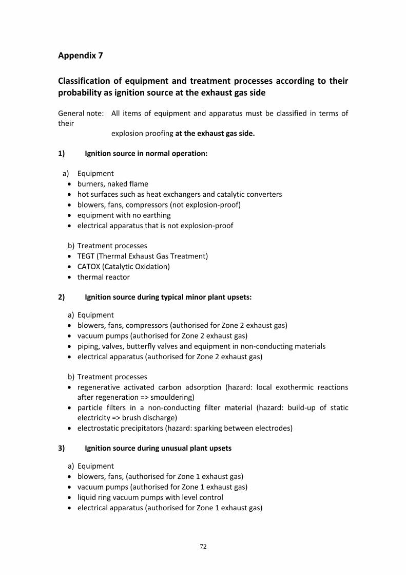
72
Appendix 7
Classification of equipment and treatment processes according to their probability as ignition source at the exhaust gas side General note: All items of equipment and apparatus must be classified in terms of their explosion proofing at the exhaust gas side. 1) Ignition source in normal operation:
a) Equipment
burners, naked flame
hot surfaces such as heat exchangers and catalytic converters
blowers, fans, compressors (not explosion-proof)
equipment with no earthing
electrical apparatus that is not explosion-proof
b) Treatment processes
TEGT (Thermal Exhaust Gas Treatment)
CATOX (Catalytic Oxidation)
thermal reactor
2) Ignition source during typical minor plant upsets:
a) Equipment
blowers, fans, compressors (authorised for Zone 2 exhaust gas)
vacuum pumps (authorised for Zone 2 exhaust gas)
piping, valves, butterfly valves and equipment in non-conducting materials
electrical apparatus (authorised for Zone 2 exhaust gas)
b) Treatment processes
regenerative activated carbon adsorption (hazard: local exothermic reactions after regeneration => smouldering)
particle filters in a non-conducting filter material (hazard: build-up of static electricity => brush discharge)
electrostatic precipitators (hazard: sparking between electrodes)
3) Ignition source during unusual plant upsets
a) Equipment
blowers, fans, (authorised for Zone 1 exhaust gas)
vacuum pumps (authorised for Zone 1 exhaust gas)
liquid ring vacuum pumps with level control
electrical apparatus (authorised for Zone 1 exhaust gas)
73
b) Treatment processes
activated carbon buffering (hazard: heat build-up cannot be excluded at high loads => local exothermic reactions)
particle filters in a conducting filter material (hazard: build-up of static electricity less probable than with non-conducting filter material)
high boiler buffering (simplified absorption process with no regeneration stage) (hazard: decomposition reaction possible due to accumulation of oxidising components)
4) No ignition source:
a) Equipment
liquid jet injectors
piping, valves, butterfly valves and equipment items in conducting materials => with specially tested earthing
electrical apparatus (authorised for Zone 0 exhaust gas)
b) Treatment processes
scrubbers*
venturi-type separators* (Ringjet, multiventuris, Symalit fabrics, etc.)
high boiler absorption*
biofilters* (hazard when allowed to dry out => moisture content control)
condensers (in conducting materials) * The associated gas blowers, fans, etc. must be assessed separately.
74
Appendix 8 Where this guide complies with Atex Directive 94/9/EC 1. This directive applies to equipment and protective systems intended for use in
potentially explosive atmospheres. 2. Safety devices, controlling devices and regulating devices intended for use in
potentially explosive atmospheres but required for or contributing to the safe functional equipment and protective systems with respect to the risks of explosion are also covered in the scope of the directive.
Annex II Clause
ATEX directive subject EPSC Guide section covering Atex
1.1 Selection of materials 4.7
1.2 Design and construction 3 & 4
1.2.4 Dust deposits 2.1.7 & 2.4.1
1.3 Potential ignition sources 2.1.4, 5.6 & Appendix 7
1.6.3 Hazards arising from power failures 4.4
1.6.4 Hazards arising from connections 4.7
2.1 Explosive atmospheres caused by gases, vapours, hazes, mists & air/dust mixtures
2.1
3.0.2 Design and positioning of protective systems 6
3.1.2 Withstanding shockwaves 2.1.6
3.1.5 Relief systems All
3.1.6 Explosion suppression systems 6.3
75
Appendix 9 Flare Stack Seals
Gas Seal/Multi-tip
Many flare tip suppliers have developed proprietary devices to improve combustion (e.g. restricted/multi-tip that increase outflow velocity and improve mixing with air at the outlet) and safety by means of “seals” at the stack/flare outlet, that avoid the air infiltration even in the stack. These limit the purge gas consumption and to prevent flash-back, but are not equivalent to flame arresters that acts as a truly protection; moreover these seals do not work in case of internal suction pressure and/or absence of purge gas.
The most common type of gas seals are:
- diffusion seals
These are labyrinths which force the incoming air to follow a path and based on the density differences between air and the gas (if purge gas is lighter, it accumulates on the top of the seal and, if heavier than air, it accumulates on the bottom) prevent air infiltration in the stack. This feature can reduce the purge gas velocity/consumption up to 0.01 fps, lowering the O2 concentration below the device to less than 0.1 % vol.
- velocity seals
These devices usually consist of a series of conical baffles in the upper part of the stack/flare that reduce the cross sectional area increasing momentum and velocity. These also act as a fictitious increase of the length of the stack that provides an additional impedance to air ingress down the stack.
76
Glossary of Terms The definitions given in this glossary are for guidance only. More detailed versions can be found in the main text or in the relevant references. AUTOIGNITION TEMPERATURE (AIT) The lowest temperature at which any fuel/oxidant mixture will spontaneously ignite. BACK PRESSURE The pressure that exists at the outlet of a pressure relief device as a result of the pressure in the discharge system. Back pressure can be either static or dynamic. Back pressure is the sum of the superimposed and built–up back pressures. BUILT-UP (DYNAMIC) BACK PRESSURE The increase in pressure in the discharge header that develops as a result of flow after the pressure relief device or devices open. CRITICAL FUEL/INERT RATIO This represents the highest ratio of fuel to inert which will prevent combustion on a mixture with air. CRITICAL OXYGEN CONCENTRATION This is the lowest concentration of oxygen (usually in nitrogen) which just supports the combustion of that fuel. DETONATION Detonation of a flammable gas or vapour with a suitable supporter of combustion is a particularly rapid and damaging type of combustion. The process is characterised by the propagation of the combustion wave at supersonic velocity. Not all flammable mixtures can detonate but in the case of mixtures for which detonation is possible, deflagrations can accelerate into detonations given suitable conditions. DETONATION INDUCTION DISTANCE In order to establish a detonation in a pipe, the advancing flame front has to accelerate until it coincides with the pressure front in the pipe. Once this has occurred, steady state detonation can become established. This process requires a finite length of pipe referred to as the run up distance. Unfortunately it has been shown that the phenomena immediately preceding steady state detonation, which are associated with these accelerating processes are even more damaging than the steady state detonation. EXPLOSION (DEFLAGRATION) This is the rapid combustion of a mixture of a flammable gas or vapour with a suitable supporter of combustion, most commonly air. The reaction procedure is characterised by the propagation of the combustion wave at subsonic velocity. All flammable mixtures can explode.
77
EXPLOSION CONTAINMENT This is the method of protection based on the design and construction of equipment to withstand the maximum explosion pressure which can be generated by the combustion of the particular gas or vapour concerned. EXPLOSION SUPPRESSION This is the method of protection based on the injection of a chemical suppressant into the system to arrest the progress of pressure development. EXPLOSION VENTING This is the method of protection in which an explosion relief device is fitted so that the reduced explosion pressure does not exceed the design pressure of the equipment. FLAME SPEED This is the velocity of propagation of a flame in a given physical situation. FLAMMABLE MIXTURE A mixture is flammable if a flame will propagate through it away from influence of the ignition source. FLAMMABILITY LIMITS Flammability limits are the minimum and maximum concentrations of a fuel in an oxidant which will allow propagation of flame away from a small ignition source. All concentrations between these limits are flammable. FLASH POINT This is the minimum temperature at which a liquid gives off sufficient vapour to form an ignitable mixture with air near the surface of the liquid. FUEL LEAN OPERATION Fuel-lean vent streams are those in which the concentration of flammable substances is below the LEL. Vent systems handling fuel-lean mixtures will remain safe should additional air enter the system unexpectedly. FUEL RICH (OXIDANT LEAN) OPERATION The concentration of flammable substances in fuel-rich vent streams is above the UEL. These mixtures are safe and will not ignite but this method of operation is much less robust and much more prone to failure than fuel-lean. INERTING Inerting is the method of protection based on reducing the oxidant concentration of the system to below the critical value by the addition of inert gas. INERT OPERATION Inerted vent streams are those in which the oxygen concentration is maintained below the Limiting oxygen concentration (LOC) necessary for combustion to take place.

78
MAXIMUM EXPLOSION PRESSURE This is the maximum pressure developed when the stoichiometric mixture of a fuel and an oxidant are ignited in standard apparatus, usually a closed spherical vessel. MIE Minimum Ignition Energy PRESSURE PILING When ignition occurs in one of two or more interconnected vessels, each containing a flammable gas mixture, combustion products and unburnt gas are transferred into the second vessel. This increases the initial pressure in the second vessel before ignition by the advancing flame front. Since the pressure ratio is the same in all vessels, the explosion pressure is considerably greater in the second and subsequent vessels than in the first. This multiplication effect is known as pressure piling. QUASI-DETONATION Normally in a steady detonation, shock front and flame zone are coupled to each other. In an unsteady detonation the shock front and flame zone can separate and the detonation is discontinued. Such phenomena have been observed in pipelines with a diameter of 250 mm and a length of 300m. STOICHIOMETRIC MIXTURE This is the mixture containing the theoretical proportions of fuel and oxidant for complete combustion.