ehp system iii-e - snaponequipment.com
TRANSCRIPT

Op
era
tor’
s M
an
ua
l M
an
ue
l d’U
tilis
atio
n M
an
ua
l de
l Op
era
do
r
EHP System III-E

2
SAFETY INFORMATION
For your safety, read this manual thoroughly before operating the Tire Changer
This tire changer is intended for use by properly trained automotive technicians. The safety mes-sages presented in this section and throughout the manual are reminders to the operator to exer-cise extreme caution when servicing tires with these products.
There are many variations in procedures, techniques, tools, and parts for mounting and demoun-ting of tires, as well as the skill of the individual doing the work. Because of the vast number of wheel and tire applications and potential uses of the product, the manufacturer cannot possibly anticipate or provide advice or safety messages to cover every situation. It is the automotive tech-nician’s responsibility to be knowledgeable of the wheels and tires being serviced. It is essential to use proper service methods in an appropriate and acceptable manner that does not endanger your safety, the safety of others in the work area or the equipment or vehicle being serviced.
It is assumed that, prior to using that tire changer, the operator has a thorough understanding of the wheels and tires being serviced. In addition, it is assumed he has a thorough knowledge of the operation and safety features of the rack, lift, or fl oor jack being utilized, and has the proper hand and power tools necessary to service the vehicle in a safe manner.
Before using the present tire changer, always refer to and follow the safety messages and service procedures provided by the manufacturers of the equipment being used and the vehicle being serviced.
IMPORTANT !! SAVE THESE INSTRUCTIONS - DO NOT DISCARD !!

3
IMPORTANT SAFETY INSTRUCTIONS
When using this equipment, basic safety precautions should always be followed, including the following:
1. Read all instructions.
2. Do not operate equipment with a damaged power cord or if the equipment has been damaged - until it has been examined by a qualifi ed authorized service technician.
3. If an extension cord is used, a cord with a current rating equal to or more than that of the machine should be used. Cords rated for less current than the equipment may overheat. Care should be taken to arrange the cord so that it will not be tripped over or pulled.
4. Always unplug equipment from electrical outlet when not in use. Never use the cord to pull the plug from the outlet. Grasp plug and pull to disconnect.
5. To reduce the risk of fi re, do not operate equipment in the vicinity of open contai-ners of fl ammable liquids (gasoline).
6. Keep hair, loose fi tting clothing, fi ngers and all parts of the body away from moving parts.
7. Adequate ventilation should be provided when working on operating internal com-bustion engines.
8. To reduce the risk of electric shock, do not use on wet surfaces or expose to rain.
9. Do not hammer any part of the machine, it isn’t designed to be an anvil.
10. Do not allow unauthorized personnel to operate the equipment.
11. Do not disable or bypass the safety systems and follow all the safety procedures.
12. Use only as described in this manual. Use only manufacturer’s recommended attachments.
13. Always securely lock the rim before actuating rotation.
14. ALWAYS WEAR SAFETY GLASSES. Everyday eyeglasses only have impact resi-stant lenses, they are NOT safety glasses.
15. The equipment is for indoor use only.
SAVE THESE INSTRUCTIONS

4
Français
Sommaire ......................................................Page 5
INSTRUCTIONS DE SECURITE’ ...................Page 7
1.0 Introduction .................................................. Page 11
1.1 Terminologie ................................................ Page 11
1.2 Caractéristiques Techniques ........................Page 13
1.3 Dimensions de la Machine ...........................Page 13
1.4 Accessoires ..................................................Page 13
1.5 Précautions Générales .................................Page 15
1.5.1 Précautions ...................................................Page 15
2.0 Montage et mise en ouvre ............................Page 17
2.1 Branchement Eléctrtique ..............................Page 17
2.2 Branchement Pneumatique ..........................Page 19
3.0 Commandes .................................................Page 21
4.0 Montage et Démontage Pneus.
Precautions générales .................................Page 25
4.1 Démontage Pneus Sans Chambre ..............Page 25
4.1.1 Utilisation du presse-talon pendant la
phase de démontage ...................................Page 29
4.2 Montage Pneus Sans Chambre (tubeless) ....Page 31
4.2.1 Utilisation du presse-talon pendant le montage ......Page 31
4.3 Gonfl age Pneus Sans Chambre (tubeless) .....Page 31
4.4 Montage et Démontage Pneus Moto ............Page 35
5.0 Démontage Pneus Avec Chambre ..............Page 35
5.1 Montage Pneus Avec Chambre ...................Page 37
5.2 Gonfl age Pneus Avec Chambre ..................Page 37
6.0 Entretien .......................................................Page 39
7.0 Mise de côté .................................................Page 41
8.0 Vente .............................................................Page 41
8.1 Consignes de démolition ....................................Page 41
English
Table Of Contents ........................................Page 4
SAFETY INSTRUCTIONS .............................Page 6
1.0 Introduction .................................................Page 10
1.1 Nomenclature ..............................................Page 10
1.2 Specifi cations ..............................................Page 12
1.3 Dimentions Of The Machine ........................Page 12
1.4 Accessories ...............................................Page 12
1.5 General Cautions ........................................Page 14
1.5.1 Precautions ................................................Page 14
2.0 Installation ...................................................Page 16
2.1 Electrical Installation ...................................Page 16
2.2 Air Installation .............................................Page 18
3.0 Controls ......................................................Page 20
4.0 Mounting And Demounting-Precautions .....Page 24
4.1 Demounting Tubeless Tires ........................Page 24
4.1.1 Use the bead presser as a Demounting
help Device .................................................Page 28
4.2 Mounting Tubeless Tires .............................Page 30
4.2.1 Use the bead presser as a Mounting
help Device ..................................................Page 30
4.3 Infl ation Of Tubeless Tires ..........................Page 30
4.4 Mounting And Demounting Motorcycle Tires ...Page 34
5.0 Demounting Tube-Type Tires ......................Page 34
5.1 Mounting Tube-Type Tires ..........................Page 36
5.2 Infl ating Tube-Type Tires ............................Page 36
6.0 Maintenance ................................................Page 38
7.0 Putting the machine out of service ...............Page 40
8.0 Disposing of the unit ....................................Page 40
8.1 Instructions for disposal ...............................Page 40

5
Revision E of 07/2010 PCN: 10G0100Nozzle lance for bead seater system BS: at page 8, 20, 28, 30, 38.Chapters 7, 8, 8.1 added: at page 38
Revision F of 07/2011 PCN: 10G0092Nozzle lance with turntable jets, replaced: at page 10, 22, 32.
Suggested oils for the fi lter/lubricator unit, replaced: at page 38.
Revision G of 11/2011- Accessories chapters Updated PCN: 11G0202 at page 12
- Logo JohnBean replaced
Revision G1 of 10/2018
- Disposing notes Updated at page 40- Air control change to 4,5 bar Updated at page 32
EC DECLARATION (Original document contained in Spare Parts Booklet)
DECLARATION CE (Le document original fi gurant dans le Liste des pièces détachées)
CE KONFORMITÄTSERKLÄRUNG (Originaldokument in der Ersatzteilliste enthaltenen)
DICHIARAZIONE CE (Originale contenuta nel Libretto Ricambi)
DECLARACIÓN CE (El original se encuentra en tabla de repuestos)
DECLARAÇÃO CE (O original está contida em Lista de peças)
- FACSIMILE -
Correggio (RE) - ITALYFrancesco Frezza
date:
ENG - complies with all the relevant regulations in the following directives:FRA - est conforme à toutes les dispositions pertinentes des directives suivantes :DEU - Allen zu folgenden Richtlinien gehörenden Bestimmungen entspricht:ITA - è conforme a tutte le disposizioni pertinenti delle seguenti direttive: POR - satisfaz todas as disposições relevantes das seguintes directivas:SPA - es conforme con todas las disposiciones pertinentes a las siguientes directivas:ALB - është konform me të gjitha dispozitat që kanë të bëjnë me direktivat e mëposhtme:BUL - ����������! "! ��#$%# &!'(�&�)*#, ��)�&+!.# �� � �/�)�!.#�� )#&�%�#�#:CES - vyhovuje v�em po�adavk0m, které se vztahují na následující sm1rnice:HRV - udovoljava svim relevantnim odredbama slijede2ih smjernica:DAN - er i overensstemmelse med bestemmelserne i følgende direktiver:EST - vastab järgmiste direktiivide kõikidele asjassepuutuvatele sätetele:FIN - on seuraavien direktiivien asiaankuuluvien säännösten mukainen:ELL - 34567 89;<=5> ;3 ?@3J K7J MQ>W@XY37J 8Z3K7[XJ ;3 K7J 6[?@>\]3J >^_`43J:ISL - er í samræmi við allar viðeigandi tilskipanir eftirfarandi reglugerða:LAV - atbilst visiem attiecxgajiem noteikumiem �{d{s direktxv{s:LIT - atitinka visus toliau nurodyt| direktyv| reikalavimus:}~D - � �� ���/!�"��� �� �#�� "�&�# �) �/�)"#�� )#&�%�#�#:}ON - je u skladu sa svim relevantnim odredbama slede2ih direktiva:NLD - overeenstemt met alle toepasselijke voorschriften van de volgende richtlijnen:POL - jest zgodna �jest zgodny� ze wszystkimi zarz�dzeniami zawartymi w nast�puj�cych dyrektywach:RU} - este fabricat în conformitate cu toate prevederile în materie din urmãtoarele directive:SLO - vyhovuje v�etkým po�iadavkám, vz�ahujúcim sa na nasledujúce smernice:SLV - v skladu z vsemi predpisi, ki se nana�ajo na naslednje direktive:S�E - överensstämmer med alla bestämmelser tillhörande följande direktiv:TUR - a�a��da belirtilen yönetmeliklere ili�kin tüm hükümlere uygundur:HUN - megfelel a következ� irányelvekbe foglalt, valamennyi rendelkezésnek:RUS - ������������� ���� (&#��"����� "�&�!� �/�)��.#� )#&�%�#�:
ENG-The }anager of the Technical Of� ce is authorised to compile a technical lea� et in compliance with appendi� VII, letter A, of the ��������CE directive FRA-Le Responsable du Bureau Technique est autorisé à constituer le fascicule technique visé sous l¡anne�e VII lettre A de la directive ��������CE DEU-Der Leiter der technischen Abteilung ist bevollmächtigt, die technischen Unterlagen zu erstellen �siehe Anhang VII, Buchstabe A der Richtlinie ��������CE ITA-Il Responsabile dell¡Uf� cio Tecnico è autorizzato a costituire il fascicolo tecnico di cui all¡allegato VII lettera A della direttiva ��������CE POR-O Responsável do Gabinete Técnico está autorizado a compilar o processo técnico, referido no ane�o VII alínea A da directiva ��������CE SPA-El Responsable del Departamento Técnico está autorizado a constituir el fascículo técnico indicado en el ane�o VII letra A de la directiva ��������CE ALB-Përgjegjësi i ¢yrës Teknike është i autorizuar të realizojë fashikullin teknik sipas dokumentit bashkëngjitur VII germa A e direktivës ��������~E BUL-£�����&"#%�� "! ¤��"#$��%#� ��)�/ � �(�/"���.�" )! ����!�# ���"#$��%!�! *&�¥�&! � ����������#� � ¦&#/�+�"#� VII, §A¨, ©#&�%�#�! ��������Eª CES-¢odpov1dný pracovník technického odd1lení je oprávn1ný vypracovat technickou dokumentaci podle p«ílohy VII ¬ásti A Sm1rnice ��������ES HRV-Odgovorna osoba Tehni¬kog ureda je ovla�tena ustrojiti tehni¬ki svezak kako se vidi u dodatku VII slovo A smjernice ��������CE DAN-Chefen i den tekniske afdeling har tilladelse til udarbejdelse af den tekniske dokumentation jf bilag VII litra A i direktivet ��������EF EST-Tehnoosakonna vastutav töötaja on volitatud koostama tehnilise toimiku vastavalt direktiivi ��������EÜ VII lisa osale A FIN-Teknisen toimiston vastuuhenkilö on valtuutettu kokoamaan tekninen eritelmä direktiivin ��������E liitteen VII kohdan A mukaisesti ELL-® ̄ M39]\5>J K>\ °3Z57[>9 ±Q6<34>\ 34567 3²>\87>^>K_;X5>J 56 M6Q³²37 K>5 K3Z57[? <³[3@> 89;<=56 ;3 K> 8\5_;;X5> VII ̀ Q³;;6 A K_J >^_`46J ��������´µ ISL-Ábyrgðarmanni tækniskrifstofunnar er heimilt að gera tækniskjalið samkvæmt A-lið VII viðauka í reglugerð ��������EB LAV-Tehnisk{s noda¶as vadxt{js ir pilnvarots sast{dxt tehnisko dokument{ciju atbilsto�i ES direktxvas ��������E~ VII pielikuma A ieda¶ai LIT-u� technin· skyri| atsakingas asmuo yra ·galiotas sudaryti technin� byl�, kurios sudarymo tvarka nurodyta Direktyvos ��������EB VII priedo A dalyje }~D-£)����&"#�� "! ���"#$%#�� �))�/ � ��/!���" )! �� ����!�# ���"#$%#�� (&#&!$"#% )!)�" �� (&#/�� VII (#��� A �) )#&�%�#�!�! ��������CE }ON-Odgovorno lice Tehni¬kog ureda je ovla�teno da sastavi tehni¬ku fasciklu kako se vidi u dodatku VII slovo A direktive ��������CE NLD-Het Hoofd van de Technische Afdeling is gemachtigd om het technisch dossier samen te stellen waarover in Bijlage VII, afdeling A, van de richtlijn ��������EG POL-~ierownik Biura Projektowego jest upowa¸niony do za¹o¸enia skoroszytu technicznego, o którym mowa w ¢a¹�czniku VII litera A dyrektywy ��������UE RU}-Responsabilul Biroului Tehnic este autorizat sã întocmeascã dosarul tehnic prevãzut în ane�a VII litera A directiva ��������CE privind echipamentele tehnice SLO-¢odpovedný pracovník technického oddelenia je oprávnený vypracova� technickú dokumentáciu podºa prílohy VII ¬asti A Smernice ��������ES SLV-Vodja tehniènega urada je poobla�èena za sestavo tehniène mape, kot navedeno v prilogi VII, èrka A direktive ��������ES S�E-Ansvarig på det tekniska kontoret har behörighet att sammanställa medföljande teknisk dokumentation i enlighet med avsnitt A i bilaga VII i direktiv ��������EG TUR-Teknik Ofis Sorumlusu ��������EC önetmeli�i¡nin VII ekinin A harfinde belirtilen teknik dosyay� haz�rlamaya yetkilidir HUN-A }»szaki Iroda Irodavezet�je feljogosított a ��������E~ irányelv A részének VII }ellékletében meghatározott, m»szaki dokumentáció összeállításáraRUS-¼�%���)#��/½ ���"#$��%��� ��)�/! �(�/"���$�" ����!�#�½ ���"#$��%#¾ /#�� � ����������## � (&#/�+�"#�� VII, /#��& A )#&�%�#�� ��������CE
ITA-Direttore Operativo SPA-Director Operativo POR-Director Operacional ENG-Operations }anager FRA-Directeur Opérationnel DEU-Betriebsleiter ALB-Drejtori Operativ BUL-£(�&!�#��" )#&�%��& CES-Výkonný «editel HRV-Operativni direktor DAN-Driftsleder EST-Tegevdirektor FIN-Operatiivinen johtaja ELL-´M7Z37Q_876[?J ¿73\]\5KÀJ ISL-Starfandi framkvæmdarstjóri LAV-Operatxvais direktors LIT-Operacij| vadovas }~D-£(�&!�#��" )#&�%��& }ON-Operativni direktor NLD-Operationeel directeur POL-Dyrektor Operatywny RU}-Director Operator SLO-Výkonný riaditeº SLV-Operativni vodja S�E-Driftledare TUR-Â�letme }üdürü HUN-Operatív Igazgató RUS - Ã(&!�/��.#¾ (&�#'��)�����
ENG - DECLARATION OF CE CONFORMITYFRA - DECLARATION CE DE CONFORMITEDEU - KONFORMITÄTSERKLÄRUNGFIN - EY-VAATIMUSTENMUKAISUUSVAKUUTUSNLD - VERKLARING VAN OVEREENSTEMMINGSWE - EG-FÖRSÄKRAN OM ÖVERENSSTÄMMELSEDAN - EF-OVERENSSTEMMELSESERKLÆRINGISL - EB-SAMRÆMISYFIRLÝSINGPOL - DEKLARACJA ZGODNO�CI �CE�RUM - DECLARA�IE DE CONFORMITATE CU NORMELE CESLO - ES VYHLÁSENIE O ZHODESLV - IZJAVA O SKLADNOSTI CEALB - DEKLARATË KONFORMITETI KEHUN - EK MEGFELEL�SÉGI NYILATKOZAT
DICHIARAZIONE CE DI CONFORMITA� - ITADECLARAÇÃO CE DE CONFORMIDADE - POR
DECLARACIÓN CE DE CONFORMIDAD - SPA���!"#"$%& '" ()*+,�+(+,%� - BUL
ES PROHLÁ�ENÍ O SHOD. - CESDEKLARACIJA CE O PODOBNOSTI - HRV
EÜ VASTAVUSDEKLARATSIOON - EST/01230 CE 34556782303 - ELL
ES ATBILST9BAS DEKLAR:CIJA - LAVATITIKTIES DEKLARACIJA - LIT
�EC� ���!"#"$%;" '" (**<#"'=*(+ - MKDDEKLARACIJA CE O USKLA>ENOSTI - MON
EC UYGUNLUK BEYANNAMES? - TUR���!"#"$%& (**+,�+(+,%& (+"=�"#+"@ �( - RUS
Snap-on Equipment Srl - Via Provinciale per Carpi, 33 - 42015 Correggio (RE) Italy
ENG - takes full responsibility for declaring that the machineQ FRA - déclare sous sa propre responsabilité que la machine Q DEU - erklärt auf eigene VerantwortungX dass die MaschineQ ITA - dichiara sotto la propria responsabilità che la macchinaQ POR - declara sob a própria responsabilidade que a máquinaQ SPA - declara bajo su propia responsabilidad que la máquinaQ ALB - deklaron nën përgjegjësinë e tij se makineriaQ BUL - [\]^_`v`_ xz[ z{|z}z`~z�{X �\ �_�v~_{_Q CES - prohla�uje na �lastní �odpo��dnostX �e strojní �a�í�eníQ HRV - i�ja�ljuje pod �lastitom odgo�orno��u da strojQ DAN - erklærer på eget ans�arX at maskinenQ EST - kinnitab omal �astutuselX et aparaatQ FIN - �akuuttaa omalla �astuullaanX että koneQ ELL - ������� �������� ¡� � ¢�£��¤Q ISL - lýsir þ�í y¥ r á eigin ábyrgð að bíllinnQ LAV - ap�in¦damies sa�u atbild§bu apliecinaX ka ma�§na¨iek¦rtaQ LIT - prisiimdama atsakomyb© skelbiaX kad ma�inaQ MKD - vª«_}¬}_ xz[ �}z«_ z[|z}z`~z�{ [\]_ �_�v~_{_Q MON - i�ja�ljuje pod �lastitom odgo�oro��u da ma�inaQ NLD - �erklaart �oor eigen �erantwoordelijkheid dat de machineQ POL - owiadc�a na w®asn¯ odpowied�ialno�X °e mas�ynaQ RUM - declarã pe propria rãspundere cã ma±inaQ SLO - �yhlasuje na �lastnú �odpo�ednos²X �e strojo�é �ariadenieQ SLV - pod lastno odgo�ornostjo i�ja�ljamoX da je strojQ SWE - försäkrar under eget ans�ar att maskinenQ TUR - kendi sorumlulu³u alt´nda makinenin a±a³´da belirtilen yönetmeliklere uygun oldu³unu beyan etmektedirQ HUN - a saját felelµssége tudatában kijelentiX hogy a gépQ RUS - � xz^~z¶ z{}\{�{}\~~z�{·¸ ª_¹}^¹\{ �{z �_�v~_
TIRE CHANGERDEMONTE-PNEUS
REIFENMONTIERMASCHINESMONTAGOMME
DEMONTADORA DE PNEUSDESMONTADOR DE NEUMÁTICOS
ÇMONTUESE GOMASH!"#$%" &" '(!)%*"+ %" ,.!$
ZOUVA/KA PNEUMATIKDEMONTIRA/ GUMA
DÆKAFMONTERINGSMASKINEREHVIVAHETUSSEADE
RENKAANVAIHTOKONE012314 5657894:4 5981;53501<
AFFELGUNARVÉLRIEPU MONTÂÞAS IEKÂRTA
PADANGØ KEITIMO PRIETAISAS'(!)%*$="> %" ,.!$
DEMONTIRKA GUMABANDENLICHTER
URZ?DZENIE DO ZDEJMOWANIA OPONDISPOZITIV DE DEMONTAT CAUCIUCURI
VYZÚVA/KA PNEUMATÍKSNEMALEC GUM
DÄCKMONTERINGSMASKINLAST@K SÖKÜCÜGUMISZERELQ
#$%)!)%*"+%X[ \*"%)]
UPDATING GUIDE
EHP System V
...

6
INFORMATIONS DE SÉCURITÉ
Pour votre sécurité, avant d’actionner le démonte-pneu EHP System V lire complètement le
présent manuel.
Le démonte-pneu électro-pneumatique EHP System est destinée à des techniciens spécialisés en appareils d’entretien automobile et formé de façon appropriée. Les consignes de sécurité présentes dans cette section et dans tout le manuel sont un aide-mémoire pour l’opérateur, pour qu’il fasse très attention lors des opérations des changeants du pneu avec ces produits.
Il existe d’innombrables procédures, techniques, outils, et parties pour changeants du pneu, tout comme le savoir-faire de chacun dans son travail. À cause des innombrables interventions possibles sur les roues, les jantes et des différentes utilisations potentielles du produit, le fabricant n’est pas en mesure d’anticiper, de suggérer ou de mettre des Messages de Sécurité pour toutes les conditions. Il incombe au technicien de l’appareil d’être bien informé des caractéristiques de la roue et la jante qui doit être remplacé. Il est essentiel d’utiliser des procédures correctes et d’exécuter les changeants des pneus de façon appropriée et acceptable, ne mettant pas en danger la sécurité de l’opérateur et celle d’autres dans la zone de travail ou l’appareil et le véhicule utilisés pour la réparation.
On présume qu’avant l’utilisation du démonte-pneu EHP System, l’opérateur a une connaissance complète des méthodes à adopter pour changeants des roues et des pneus. En outre, il est sous-entendu qu’il a une connaissance complète des caractéristiques de fonctionnement et de sécurité concernant le pont ou l’élévateur utilisé ou élévateur au sol soit utilisé, et qu’il dispose des outils manuels ou électriques nécessaires à l’exécution du service au véhicule, en condition de sécurité.
Avant d’utiliser le démonte-pneu EHP
System, se reporter toujours aux messages de sécurité et aux procédures de service fournis par les fabricants de l’équipement utilisé et du véhicule en réparation.
IMPORTANT!! CONSERVER CES INSTRUCTIONS - NE PAS LES SUPPRIMER!!
SAFETY INFORMATION
For your safety, read this manual thoroughly before operating the
EHP System V Tire Changer
The EHP System Tire Changers are intended for use by properly trained automotive technicians. The safety messages presented in this section and throughout the manual are re-minders to the operator to exercise extreme care when changing tires with these products.
There are many variations in proce-dures, techniques, tools, and parts for changing tires, as well as the skill of the individual doing the work. Because of the vast number of wheel and tire applications and potential uses of the product, the manufacturer cannot pos-sibly anticipate or provide advice or safety messages to cover every situ-ation. It is the automotive technician’s responsibility to be knowledgeable of the wheels and tires being changed. It is essential to use proper service methods and change tires in an ap-propriate and acceptable manner that does not endanger your safety, the safety of others in the work area or the equipment or vehicle being serviced.
It is assumed that, prior to using the EHP System Tire Changers, the oper-ator has a thorough understanding of the wheels and tires being changed. In addition, it is assumed he has a thor-ough knowledge of the operation and safety features of the rack, lift, or fl oor jack being utilized, and has the proper hand and power tools necessary to service the vehicle in a safe manner.
Before using the EHP System Se-ries Tire Changers, always refer to and follow the safety messages and service procedures provided by the manufacturers of the equipment being used and the vehicle being serviced.
IMPORTANT !! SAVE THESE INSTRUCTIONS — DO NOT
DISCARD !!

7
Il n’est pas possible d’utiliser ensemble des pneus et des jantes de diamètre différent.• Ne JAMAIS essayer de monter ou de gonfl er un pneu et une jante de diamètre différent.• S’assurer TOUJOURS que les diamètres du pneu et de la jante correspondent bien. L’utilisation d’un pneu et d’une jante de diamètre
différent pourrait provoquer une explosion, avec
risques d’accident mortel ou de blessures graves.
Un pneu surgonfl é peut exploser et projeter des fragments. • Lire et comprendre le manuel de l’utilisateur avant l’utilisation. • Empêcher l’accès des personnes étrangères au service à la zone de travail.• TOUJOURS utiliser des lunettes de protection.• S’assurer TOUJOURS que les diamètres du pneu et de la jante correspondent bien.• NE JAMAIS essayer de monter ou de gonfl er un pneu et une jante de diamètre différent.• Inspecter les pneus. NE JAMAIS gonfl er des pneus endommagés ou usés.• NE JAMAIS gonfl er des roues à jante divisée sur ce démonte-pneu ou bien les démonter et utiliser uniquement une cage de gonfl age de sécurité agréée et conçue à cet effet. • Bloquer la fi xation de la plaque tournante à l’intérieur de la jante avant de commencer à gonfl er le pneu. • Utiliser un lubrifiant pour talon avant de démonter ou de monter le pneu sur la jante.• Placer toujours le “bras de maintien de sécurité ” sur la roue pour la maintenir fi xée à la plaque tournant pendant le gonfl age en cas d’équipement de ce genre.• Si un pneu explose sur ce démonte-pneu, ARRETER de l’utiliser jusqu’à ce que le “bras de maintien de sécurité ” ait été remplacé, ce qui doit être fait même si aucun dommage n’est apparent.• NE JAMAIS placer la tête ou le corps au-dessus d’un pneu pendant le gonfl age.• Utiliser de petites injections d’air pour mettre en place sur les talons du pneu. Contrôler la pression de l’air du pneu, fréquemment. NE JAMAIS dépasser les limites de pression indiquées par le fabricant..• NE JAMAIS essayer de dériver ou d’altérer le limiteur de pression incorporé. Ne gonfl er le pneu qu’avec l’embout fourni avec le démonte-pneu. NE JAMAIS utiliser l’embout de gonfl age de l’atelier pour gonfl er un pneu.• Le démonte-pneu doit être fi xé au sol en béton s’il est équipé d’un “bras de maintien de sécurité”.L’explosion d’un pneu peut provoquer des blessures graves.
Tires and Rims that are not the same diameter are mismatched.• NEVER attempt to mount or infl ate any tire and rim that are mismatched.• ALWAYS check to see that tire and rim diameters are the same. A mismatched tire and rim will explode causing
death or serious personal injury
Over-pressurized tires can explode causing fl ying debris. • Read and understand Operator’s Manual before operating.
• Keep bystanders away from work area.
• ALWAYS wear Safety Goggles.
• ALWAYS check to see that Tire and Rim diameters are the same.
• NEVER attempt to mount or infl ate any Tire and Rim with different diameters.
• Inspect tires, NEVER infl ate tires that are damaged, rotten or worn.
• NEVER infl ate ‘Split Rim Wheels’ on this tire changer, remove them and use only an approved safety infl ation cage designed for this purpose.
• Lock turntable Clamp on inside of rim before attempting to infl ate tire.
• Use approved tire bead lubricant before removing or installing tire on rim.
• ALWAYS position the “Safety Restraint Arm” over the wheel to hold it to the turntable while infl ating if so equipped.
• If a tire explodes on this tire changer, STOP using it until the “Safety Restraint Arm” has been replaced, which must be done even if no damage is seen.
• NEVER place head or body over a tire during infl ation process.
• Use short bursts of air to seat tire beads, check tire air pressure frequently.
• NEVER exceed tire manufacturer’s pressure limits.
• NEVER attempt to bypass or alter the built in air pressure limiter. Only infl ate tire with air hose supplied with tire changer. NEVER use shop infl ation hose to infl ate a tire.
• Tire Changer must be anchored to concrete fl oor if equipped with a “Safety Restraint Arm”
Exploding Tires can cause serious injury.

8
INSTRUCTIONS: Safety Label Meanings IMPORTANT!! SAVE THESE INSTRUCTIONS
Overinfl ated tires or tires mounted on the wrong sized rims can explode producing hazardous fl ying debris.• Read and understand the operation instructions before using this tire changer.• Never mount tire on rim with different sized diameter.• Never exceed maximum infl ation pressure listed on tire sidewall.• Always use safety restraint arm to hold wheel in place while infl ating.• Always use attached air hose to infl ate tires.Exploding tires can cause death or serious injury.
Risk of electrical shock.• Do not operate equipment with a damaged power cord or if the equipment has been dropped or damaged,
until it has been examined by a qualifi ed service person.• If an extension cord is necessary, a cord with a current rating equal to or greater than that of the
equipment should be used. Cords rated for less current than the equipment can overheat.• Unplug equipment from electrical outlet when not in use. Never use the cord to pull the plug from the
outlet. Grasp plug and pull to disconnect.• Do not expose the equipment to rain. Do not use on wet surfaces.• Plug unit into correct power supply.• Do not remove or bypass grounding pin.Contact with high voltages can cause death or serious injury.
Risk of electrical shock. High voltages are present within the unit.• There are no user serviceable items within the unit.• Service on the unit must be performed by qualifi ed personnel.• Do not open any part of the unit other than noted and allowed areas.• Turn power switch off and unplug the unit before servicing.Contact with high voltages can cause death or serious injury.
Risk of crushing.• Become familiar with all controls before proceeding with operation.• Stand away from the bead breaker arm when in operation.• Apply air to breaker in bursts if necessary to control arm depth.• Don’t allow to approach extraneous people to the service.Contact with moving parts could cause injury.
Risk of pinching or crushing hands and fi ngers.• Keep hands and fi ngers clear of rim edge during demounting and mounting process.• Keep hands and fi ngers clear of mount/demount head during operation.• Keep hands and other body parts away from moving surfaces.• Do not use tools other than those supplied with tire changer. • Do not use unapproved accessories• Do not bypass any safety features.• Use proper tire lubricant to prevent tire binding.Contact with moving parts could cause injury.
Risk of eye injury. Debris, dirt, and fl uids may drop from wheels.• Remove any debris from tire tread and wheel surfaces.• Remove excess tire lubricant before infl ating.• Knock off any loose debris. Clean surfaces as needed to avoid any materials from falling.• Wear approved safety glasses during mount and demount procedures.Debris, dirt, and fl uids projection can cause serious eye injury.
Risk of injury. Tools may break or slip if improperly used or maintained.• Use the correct tool for the task.• Frequently inspect, clean, and lubricate (if recommended) all tools.• Follow recommended procedures when performing wheel services.Tools that break or slip can cause injury.

9
INSTRUCTIONS : Lecture de la plaque de sécuritéIMPORTANT!! CONSERVER LES PRESENTES INSTRUCTIONS
Les pneus surgonfl és ou les pneus montés sur des jantes de taille non appropriée peuvent exploser et projeter des fragments.• Lire et comprendre le manuel d’utilisation avec d’utiliser ce démonte-pneu.• Ne jamais monter ou gonfl er un pneu et une jante de diamètre différent.• Ne jamais dépasser les limites de pression indiquées sur le côté du pneu.• Toujours utiliser le bras de maintien de sécurité pour maintenir la roue en place pendant le gonfl age.• Toujours utiliser l’embout fourni pour gonfl er les pneus.L’explosion des pneu peut causer un accident mortel ou des dommages graves.
Risque électrique.• Ne pas démarrer l’appareil si le câble d’alimentation est endommagé ou après une chute ou en présence
de dommages, tant qu’il n’a pas été examiné par une personne qualifi ée du SAV.• Si une rallonge est nécessaire, utiliser un câble ayant une valeur de courant égale ou supérieure au courant
utilisé pour l’appareil. Un câble d’une valeur inférieure pourrait se surchauffer.• Quand il n’est pas utilisé, déconnecter toujours l’appareil du coffret électrique. Ne jamais saisir le câble
pour enlever la fi che du coffret. Saisir la fi che électrique et tirer pour débrancher.• Ne pas exposer l’appareil à la pluie. Ne pas utiliser sur des surfaces humides.• Connecter l’unité à la bonne prise d’alimentation.• Ne pas enlever ou désactiver le câble de terre.Le contact avec d’autres tensions peut causer la mort ou des dommages graves.
Risque électrique. De hautes tensions sont présentes à l’intérieur de l’unité.• A l’intérieur de l’unité n’existent pas parties relevant de la compétence de l’opérateur.• Les interventions d’assistance sur l’unité doivent être effectuées par du personnel qualifi é.• Ne pas ouvrir de parties non connues ou non admise de l’appareil.• Éteindre l’interrupteur et déconnecter l’unité avant toute intervention de service.Le contact avec des hautes tensions peut causer la mort des dommages graves.
Risque d’écrasement.• Se familiariser avec toutes les commandes avant toute utilisation.• Rester à distance de sécurité du bras de l’outil de décollage pendant le fonctionnement.• Appliquer l’air sur l’outil de décollage par à-coups si nécessaire pour contrôler la profondeur du bras.• Empêcher les personnes étrangères au service de s’approcher du démonte-pneu.Le contact avec des parties en mouvement peut causer un accident.
Risque de pincement ou d’écrasement des mains et des doigts.• Garder les mains et les doigts à distance de sécurité du bord de la jante pendant les opérations de
démonte et de monte.• Garder les mains et les doigts à distance de sécurité de la tête de monte/démonte pendant le fonctionnement.• Garder les mains et autres parties du corps à distance de sécurité des surfaces en mouvement.• Ne pas utiliser d’outils autres que ceux fournis avec le démonte-pneu. • Ne pas utiliser d’accessoires non autorisés• Ne désactiver aucun dispositif de sécurité.• Utiliser un lubrifi ant approprié pour éviter le grippage du penu.Le contact avec des parties en mouvement peut causer des accidents.
Risque de dommage aux yeux. Des projections de fragments, de saleté et de liquides peuvent se produire pendant les opérations de mise en place du talon et de gonfl age.• Enlever tous les fragments de la bande de roulement et de la jante.• Enlever l’excédent de lubrifi ant pour pneus avant de gonfl er.• Tapoter pour éliminer les fragments. Nettoyer les surfaces suffi samment pour éviter la chute de matériaux.• Porter des lunettes de sécurité approuvées pendant les interventions de service.Les fragments, les déchets et les fl uides peuvent causer des dommages graves aux yeux.
Risque de dommage. Les outils peuvent se briser ou glisser s’ils sont utilisés ou conservés de façon non appropriée.• Utiliser l’outil adapté pour cette fonction.• Inspecter, nettoyer et lubrifi er (si cela est recommandé) fréquemment tous les outils.• Suivre les procédures recommandées lors des interventions sur le roues.Les outils qui se brisent ou glissent peuvent provoquer des dommages.

10
1.1-1
540.tif
1.0 Introduction
Congratulations on purchasing the “EHP System V” electric/air tire changer.This tire changer is designed for ease of operation, safe handling of rims, reliability and speed.This combination of features means more profi t and added versatility for your shop, enabling you to work with aluminium or magnesium alloy wheels without damaging customer’s rims.With a minimum of maintenance and care your tire changer will provide many years of trouble-free operation.Please read this manual thoroughly before operating the unit. Instructions on use, maintenance and operational requirements of the machine are covered in this manual.
STORE THIS MANUAL IN A SAFE PLACE FOR FUTURE REFERENCE. READ THIS MANUAL THOROUGHLY BEFORE USING THE MACHINE.
1.1 Nomenclature
Before installing and using the electric/air tire changer it is suggested that you become familiar with the nomenclature of the machine’s components (Fig. 1.1-1).
1 Vertical slide2 Mounting arm, horizontally displaceable3 Lever with push-button4 Handle5 Mount/demount tool6 Tower or column7 Turntable8 multi-position Jaw9 Bead breaker arm10 Bead breaker blade11 Bead breaker pads12 Air jets13 Foot pedal controls14 Bead seater/infl ator pedal15 Infl ation gauge
16 Bottom bead roller17 Top bead roller18 Bead assist arm19 Rise/fall control lever20 Bead depressor arm21 Bead depressor tool
ALL ELECTRICAL CONNECTIONS SHALL BE PERFORMED BY A LICENCED TECHNICIAN. ALL SERVICE MUST BE PERFORMED BY AN AUTHORIZED SERVICE TECHNICIAN.

11
1.0 Introduction
Félicitations pour avoir acheté le démonte-pneu électro-pneumatique “EHP System V”.Cet ensemble de caractéristiques signifie pour votre entreprise des profi ts plus élevés ainsi qu’une polyvalence majeure car il vous permet de travailler sur des roues en alliage aluminium ou magnésium sans endommager la jante.Avec un minimum d’entretien et de soin, ce démonte-pneu vous garantit de nombreuses années de travail rentable et sans problèmes.Lisez attentivement ce manuel avant de mettre la machine en service.Les instructions sur l’emploi, l’entretien et les modalités d’emploi sont décrites dans ce manuel.
CONSERVER SOIGNEUSEMENT CE MANUEL POUR TOUTE CONSULTATION. LIRE ATTENTIVEMENT CE MANUEL AVANT D’UTILISER LA MACHINE
1.1 Terminologie
Avant d’installer et d’utiliser le démonte-pneus, on conseille de se familiariser avec la terminologie de la machine (Fig. 1.1-1).
1. Tige verticale2. Bras de montage, à déplacement horizontal3. Levier avec bouton-poussoir4. Béquille5. Outil6. Potence7. Autocentreur8. Mors avec positionnement9. Bras détalonneur10. Palette détalonneur11. Support détalonneur12. Jets d’air13. Pédalier14. Pédale de gonfl age15. Manomètre de gonfl age
16. Disque presse-tallon inférieure17. Rouleau Superieur18. Tige horizontale19. Levier de commande20. Bras presse-talon21. Outil presse-talon
T O U T E S L E S I N T E R V E N T I O N S S U R L’INSTALLATION ÉLECTRIQUE DOIVENT ÊTRE RÉALISÉES PAR UN PERSONNEL PROFESSIONNELLEMENT QUALIFIÉ. TOUTES LE RÉPARATIONS DOIVENT ÊTRE EFFECTUÉES PAR DES TECHNICIENS AGRÉÉS
12
1.3-1
1.4-1
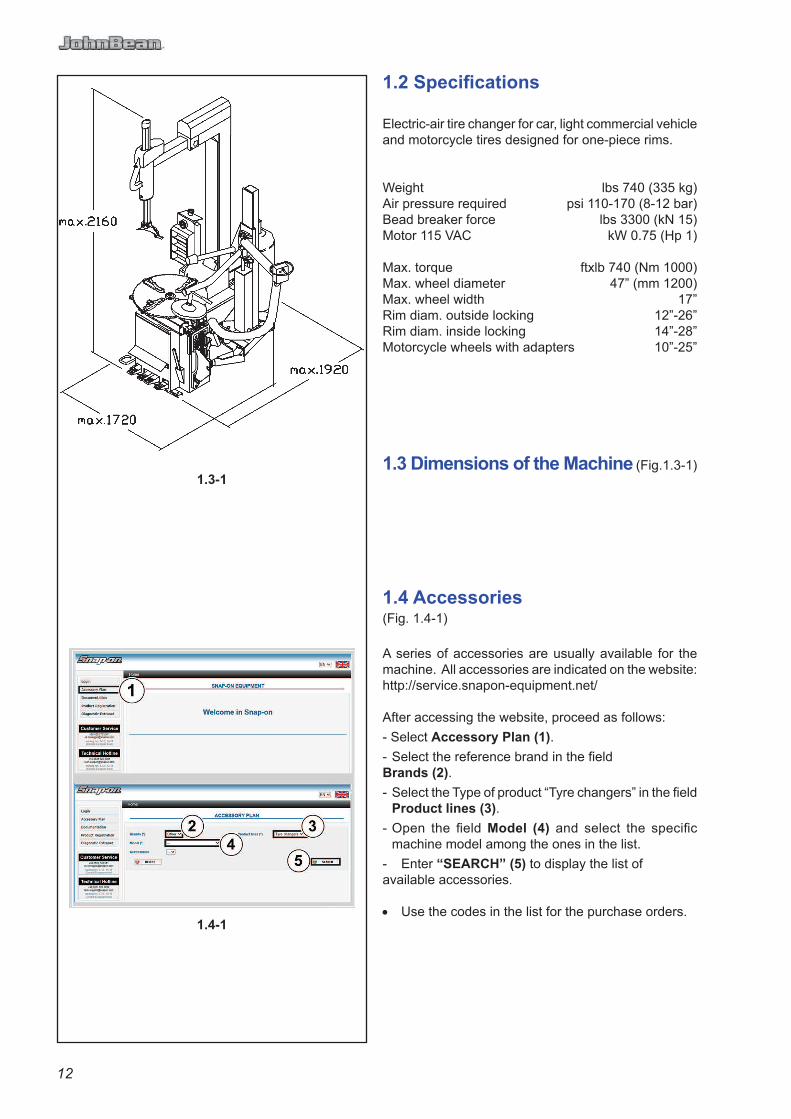
1.2 Specifi cations
Electric-air tire changer for car, light commercial vehicle and motorcycle tires designed for one-piece rims.
Weight lbs 740 (335 kg)Air pressure required psi 110-170 (8-12 bar)Bead breaker force lbs 3300 (kN 15)Motor 115 VAC kW 0.75 (Hp 1)
Max. torque ftxlb 740 (Nm 1000)Max. wheel diameter 47” (mm 1200)Max. wheel width 17”Rim diam. outside locking 12”-26”Rim diam. inside locking 14”-28”Motorcycle wheels with adapters 10”-25”
1.3 Dimensions of the Machine (Fig.1.3-1)
1.4 Accessories(Fig. 1.4-1)
A series of accessories are usually available for the machine. All accessories are indicated on the website: http://service.snapon-equipment.net/
After accessing the website, proceed as follows:
- Select Accessory Plan (1).
- Select the reference brand in the fi eld Brands (2).
- Select the Type of product “Tyre changers” in the fi eld Product lines (3).
- Open the fi eld Model (4) and select the specifi c machine model among the ones in the list.
- Enter “SEARCH” (5) to display the list of available accessories.
• Use the codes in the list for the purchase orders.

13
1.2 Caractéristiques techniques
Démonte-pneus électro-pneuma-tique pour roues de voiture, de fourgon et de moto avec pneus montés sur jantes à base creuse.
Poids lbs 740 (335 kg)Pression air comprimé psi 110-170 (8-12 bar)Force détalonneur lbs3300 (kN 15)Moteur 115 VAC kW 0.75 (Hp 1)
Couple maximum ftxlb 740 (Nm 1000)Diamètre maxi. de roue. 47” (mm 1200)Largeur maxi. de roue 17”Blocage par l’extérieur 12”-26”Blocage par l’intérieur 14”-28”Blocage roues moto avec adaptaeurs 10”-
25”
1.3 Dimensions de la machine (Fig.1.3-1)
1.4 Accessoires(Fig. 1.4-1)
Une série d’accessoires sont normalement disponibles avec la machine. Tous les accessoires sont listés sur le site web : http://service.snapon-equipment.net/
Une fois entré dans la page web, procéder comme suit.
- Sélectionner Accessory Plan (1).
- Sélectionner la Marque de référence dans la rubrique Brands (2).
- Sélectionner le type de produit «Tyre changers» dans la rubrique Product lines (3).
- Ouvrir la rubrique Model (4) et sélectionner le modèle de machine désiré dans la liste.
- Taper «SEARCH» (5) pour affi cher la liste des accessoires disponibles.
• Pour les commandes, prière d’utiliser les codes mentionnés dans la liste.

14
D
B
EarthSign.tif
1.5 General Cautions
A. DURING USE AND MAINTENANCE OF THE MACHINE IT IS MANDATORY TO COMPLY WITH ALL LAWS AND REGULATIONS FOR ACCIDENT PREVENTION.B. THE ELECTRICAL POWER SOURCE MUST HAVE A GROUND CABLE AND THE GROUND CABLE OF THE MACHINE (YELLOW WITH GREEN) MUST BE CONNECTED TO THE GROUND CABLE OF THE POWER SOURCE.C. BEFORE PERFORMING ANY MAINTENANCE OR REPAIRS THE MACHINE MUST BE DISCONNECTED FROM THE AIR AND ELECTRIC SUPPLY.D. NEVER WEAR TIES, CHAINS OR OTHER LOOSE ARTICLES WHEN USING, MAINTAINING OR REPAIRING THE MACHINE. LONG HAIR IS ALSO DANGEROUS AND SHOULD BE KEPT UNDER A HAT.THE USER MUST WEAR PROPER SAFETY ATTIRE I.E.: GLOVES, SAFETY SHOES AND GLASSES. E. MAINTAIN ALL ELECTRIC CORDS IN GOOD REPAIR.F. KEEP SAFETY FEATURES IN PLACE AND IN WORKING ORDER.G. KEEP WORKING AREA CLEAN. CLUTTERED AREAS INVITE ACCIDENTS.H. AVOID DANGEROUS ENVIRONMENTS. DON’T USE POWER TOOLS OR ELECTRICAL EQUIPMENT IN DAMP OR WET LOCATIONS, OR EXPOSE THEM TO RAIN.J. KEEP THE WORK AREA WELL LIGHTED.
1.5.1 PrecautionsTHE USE OF THIS DEVICE IS ALLOWED ONLY TO PERSONNEL DULY TRAINED BY AN AUTHORIZED JBC
DEALER.
ANY MISUSE OR MODIFICATION OF THIS DEVICE OR OF ITS PARTS OR COMPONENTS NOT PREVIOUSLY AUTHORIZED BY THE MANUFACTURER WAIVE THE MANUFACTURER FROM ANY DAMAGE CONSEQUENT OR RELATED TO THE ABOVE MENTIONED MISUSES.
REMOVING OR BYPASSING SAFETY DEVICES OR WARNING LABELS OF THE MACHINE IS A VIOLATION OF THE SAFETY REGULATIONS.
THE USE OF THIS DEVICE IS ALLOWED ONLY IN LOCATIONS WITH NO EXPLOSION OR FIRE HAZARD.
THIS EQUIPMENT IS DESIGNED TO RECEIVE ORIGINAL SPARE PARTS AND ACCESSORIES ONLY.
THE INSTALLATION SHALL BE CARRIED OUT ONLY BY QUALIFIED PERSONNEL AND WITHIN THE SCOPE OF THE INSTRUCTIONS PROVIDED IN THIS MANUAL.
IN CASE A DEFECTIVE FUNCTIONING CONDITION IS DETECTED, STOP USING THE MACHINE AND CALL THE AUTHORIZED JBC DISTRIBUTOR FOR ASSISTANCE.

15
1.5 Précautions générales
A. PENDANT L’UTILISATION ET L’ENTRETIEN DE LA MACHINE IL EST IMPÉRATIF DE RESPECTER TOUTES LES LOIS ET LES RÈGLES POUR LA PRÉVENTION DES ACCIDENTS.B. LA LIGNE D’ALIMENTATION ELECTRIQUE DOIT AVOIR UNE MISE A LA TERRE ET LE CABLE DE TERRE DE LA MACHINE (JAUNE ET VERT) DOIT ETRE BRANCHE AU CABLE DE TERRE DE LA LIGNE ELECTRIQUE.C. AVANT TOUTE OPÉRATION D’ENTRETIEN ET DE RÉPARATION LA MACHINE DOIT ÊTRE DEBRANCHÉE DU RÉSEAU ÉLECTRIQUE ET DE L’AIR COMPRIMÉ.D. NE PORTER JAMAIS DE CRAVATES, DE CHAÎNES OU AUTRES LORSQUE L’ON ÉXÉCUTE DES OPÉRATIONS D’EMPLOI, D’ENTRETIEN OU DE RÉPARATION SUR LA MACHINE. LES CHEVEUX LONGS SONT ÉGALEMENT DANGEREUX. ILS DOIVENT ÊTRE RASSEMBLÉS SOUS UNE CASQUETTE OU AUTRE. L’OPÉRATEUR DOIT PORTER DES VÊTEMENTS ADÉQUATS, DES GANTS, DES CHAUSSURES DE SÉCURITÉ ET DES LUNETTES. E. LES CÂBLES ÉLECTRIQUES DOIVENT ÊTRE CONSERVÉS EN BON ÉTAT.F. LE CARTER DE SÉCURITÉ ET LES DISPOSITIFS DE SÉCURITÉ DOIVENT ÊTRE ACTIFS ET DOIVENT FONCTIONNER CORRECTEMENT.G. LA ZONE DE TRAVAIL DOIT ÊTRE PROPRE. LES ENDROITS DESORDONNÉS FAVORISENT LES ACCIDENTS. H. ÉVITER LES SITUATIONS DANGEREUSES. NE PAS UTILISER D’OUTILS PNEUMATIQUES OU ÉLECTRIQUES DANS DES LIEUX HUMIDES ET GLISSANTS, NE PAS LES EXPOSER AUX INTEMPÉRIES.J. LA ZONE DE TRAVAIL DOIT ÊTRE BIEN ÉCLAIRÉE.
1.5.1 Précautions-L’EMPLOI DE L’APPAREIL EST PERMIS SEULEMENT AU PERSONNEL OPPORTUNÉMENT FORMÉ PAR LE DISTRIBUTEUR AUTORISÉ JBC.-TOUT ET N’IMPORTE QUEL CHANGEMENT OU MODIFICATION DE L’APPAREIL OU DE L’UNE SES PIÈCES QUI N’A PAS ÉTÉ AUTORISÉ PAR LE CONSTRUCTEUR, DÉCHARGE CELUI-CI DES DOMMAGES CAUSÉS PAR OU RAPPORTABLES AUX ACTIONS SUSMENTIONNÉES.-LA LEVÉE OU L’ALTÉRATION DES DISPOSITIFS DE SÉCURITÉ OU D’INSTRUCTIONS PLACÉS SUR LA MACHINE ENTRAÎNE UNE VIOLATION DES RÈGLES SUR LA SÉCURITÉ.L’EMPLOI DE L’APPAREIL EST PERMIS SEULEMENT EN LIEUX SANS DANGER D’EXPLOSION OU D’INCENDIE.-L’INSTALLATION DOIT ÊTRE EFFECTUÉE PAR DU PERSONNEL QUALIFIÉ DANS LE RESPECT DES INSTRUCTIONS DONNÉES.-CETTE MACHINE A ETE CONÇUE POUR NE MONTER QUE DES ACCESSOIRES ET DES PIÈCES DE RECHANGE D’ORIGINE. -CONTRÔLER QUE PENDANT LES MANOEUVRES AUCUNE CONDITION DE DANGER NE SE VERIFIE. LE CAS ÉCHÉANT, ARRÊTER IMMÉDIATEMENT LA MACHINE.-S I L’ON REMARQUE DES IRRÉGULARITÉS FONCTIONNELLES, ARRÊTER LES OPÉRATIONS ET CONSULTER LE SERVICE APRÈS-VENTE DU DISTRIBUTEUR AUTORISÉ JBC.

16
2.0-1
540.tif
2.0 InstallationInstall the machine in a covered and dry place. Operation temperature is +41/+122 °F (+5/50° C). The machine can work below 32 °F (0° C), but some minor modifi cations are required: contact your JBC distributor for detailed information.
A. Remove the screws that attach the machine to the pallet.
B. Lift the machine with an appropriate lifting tool (crane, fork lift) and a belt of suffi cient capacity (3500 N).For this operation, it is required to be helped by a second person. Always mind the center of gravity of the machine (Fig 2.0-1).BE CAREFUL NOT TO DAMAGE THE AIR HOSES.
C. Remove the safety means from the mounting arm.
D. When fi rst setting the machine into operation, check hose connections and unions for leakage.
E. The machine must be secured to the fl oor through the holes provided in the cabinet.Expansion screws 12x120mm shall be used.Drill 12mm holes in the floor flush with the holes provided in the cabinet.Place the nogs into the holes drilled in the fl oor and move the machine so that the holes of the cabinet are fl ush with the holes in the fl oor. Tighten the screws at 70 Nm (51 ftxlb).
2.1 Electrical InstallationWARNINGALL ELECTRICAL CONNECTIONS SHALL BE PERFORMED BY A LICENCED TECHNICIAN. ALL SERVICE MUST BE PERFORMED BY AN AUTHORIZED SERVICE TECHNICIAN.
FOR ELECTRIC MOTOR TYPE ONLY:Check that the electrical specifi cations of the power source are the same of the machine. The machine uses 0.75 kW. Electric specifi cations are clearly marked on a label at the end of the electric cord.If the plug is provided disregard this paragraph.Connect the electric cord of the machine with an approved plug. The ground cable (green and yellow) must be properly connected.
WARNING!FAILURE TO PROVIDE PROPER ELECTRICAL SUPPLY AND GROUNDING WILL CREATE A SHOCK HAZARD TO THE OPERATOR.
NOTE: AIR MOTOR POWERED MACHINE D O E S N ’ T N E E D E L E C T R I C A L INSTALLATION.

17
2.0 Montage et mise en oeuvreInstaller la machine dans un lieu couvert et sec. La température de service est de +41/+122 °F (+5/50 °C). La machine peut fonctionner au-dessous de 32 °F, mais cela exige quelques petites modifi cations. Contactez votre distributeur JBC pour de plus amples informations.
A. Enlever les vis qui fi xent la machine à la palette.
B. Soulever la machine avec un moyen de levage adéquat (palan, chariot élévateur) et une courroie ayant une charge d’utilisation suffisante (3500N). Pour le montage de la machine, deux opérateurs sont nécessaires et ils devront veiller au centre de gravité de la machine (Fig. 2.0.1).ATTENTION! NE PAS ABIMER LES TUBES DE L’AIR.
C. Enlever les moyens de sécurité en bois du bras de montage.
D. Pendant la première mise en service, contrôler les raccords du tuyau pneumatique s’ils présentent des fuites.
E. La machine doit être fi xée au sol par les logements spéciaux troués placés sur l’empattement.On doit utiliser des chevilles pour vis de 12x120. On doit faire des trous en correspondance des ouvertures prévues avec une perceuse avec un foret de 12 mm. Ensuite, introduire les chevilles et placer la machine en correspondance des trous ainsi préparés. Introduire les vis et serrer avec une clé dynamométrique étalonnée à 70 Nm (51 ftxlb).
2.1 Branchement électriqueAVERTISSEMENT ! TOUTES LES INTERVENTIONS SUR L’INSTALLATION ÉLECTRIQUE DOIVENT ÊTRE RÉALISÉES PAR UN PERSONNEL PROFESSIONNELLEMENT QUALIFIÉ. TOUTES LE RÉPARATIONS DOIVENT ÊTRE EFFECTUÉES PAR DES TECHNICIENS AGRÉÉS
VERSION AVEC MOTEUR ELECTRIQUE SEULEMENT:Contrôler attentivement sur la plaquette des données du constructeur, que les caractéristiques électriques de l’installation correspondent à celles du reseau. La machine nècessite 075 kW. Les caractéristiques électriques sont indiquées clairement sur une étiquette au bout du câble électrique. Relier le câble électrique de la machine à une fi che homologuée. Le câble de terre (jaune et vert) doit être branché correctement.
ATTENTION!UNE INSTALLATION ELECTRIQUE NON CONFORME PEUT CONSTITUER UN RISQUE D’ELECTROCUTION POUR L’OPERATEUR.
NOTE : LA VERSION AVEC MOTEUR PNEUMATIQUE NE NECESSITE PAS D’INSTALLATION ELECTRIQUE.

18
2.2 Air Installation
WARNING
THE AIR INSTALLATION MUST BE MADE ONLY BY LICENSED PERSONNEL.
WARNING
EXCESSIVE AIR PRESSURE CAN SERIOUSLY INJURE PERSONNEL AND DAMAGE THE MACHINE.
Ensure that the line pressure is within the limits required by the machine. If the air pressure exceeds 12 bar (170 psi) it is mandatory to install a pressure regulator before the air inlet of the machineIt is suggested that the air supply be equipped with a water separator and air lubricator.
After ensuring all the above proceed as follows:
A.FOR ELECTRIC MOTOR POWERED VERSION ONLY:Connect the machine to the air supply with a rubber hose equipped with 1/4”NPT treaded junction.
FOR AIR MOTOR POWERED VERSION ONLY:Connect the machine to the air supply with a rubber hose equipped with 3/8”NPT treaded junction.
WARNING
BEFORE CONNECTING THE MACHINE TO THE AIR SUPPLY BE SURE ALL PERSONNEL ARE CLEAR OF THE MACHINE AND THAT NOTHING IS LEFT ON THE TURNTABLE AREA (TOOLS)
B. Should you install any optional accessories, please refer to the relevant instructions.

19
2.2 Branchement pneumatique
AVERTISSEMENT ! L’ I N S TA L L AT I O N P N E U M AT I Q U E D O I T ÊTRE EFFECTUÉE PAR DU PERSONNEL PROFESSIONNELLEMENT QUALIFIÉ.
AVERTISSEMENT ! UNE PRESSION PNEUMATIQUE EXCESSIVE PEUT COMPROMETTRE LA SECURITE DU PERSONNEL ET ENDOMMAGER LA MACHINE.
Contrôler si la pression du réseau est dans les limites demandées. Si la pression est supérieure à 12 bar (170 psi), il faut installer un régulateur de pression avant la prise d’air de la machineOn conseille de monter sur le réseau de l’air comprimé un fi ltre supplémentaire
Après avoir effectué tous ces contrôles, procéder comme il suit:
A. POUR VERSION AVEC MOTEUR ELECTRIQUE :Relier la machine à la ligne de l’air comprimé, avec un tuyau en caoutchouc complet de cosse mâle avec fi let 1/4”NPT.
POUR VERSION AVEC MOTEUR PNEUMATIQUE :Relier la machine à la ligne de l’air comprimé, avec un tuyau en caoutchouc complet de cosse mâle avec fi let 3/8”NPT.
AVERTISSEMENT ! AVANT DE RELIER LA MACHINE AU RÉSEAU DE L’AIR COMPRIMÉ, CONTRÔLER QUE RIEN NE SOIT LAISSÉ SUR L’AUTOCENTREUR (OUTILISETE)
B. Si l’on veut installer n’importe quel accessoire en option, il faut suivre les instructions de montage jointes.

20
3.0-1
3.0-2
A
982a.tif
B
983a.tif
C
984a.tif
3.0 ControlsBefore operating the machine, ensure that you have well understood the operation and function of all the controls (Fig.3.0-1).
A. Press down and release, WITH LEFT FOOT, the fi rst pedal from the left: the column tilts backwards.Do it again: the column tilts forward.
WARNINGDANGER OF BODY CRUSHING
TO MINIMIZE THE RISK OF SCRATCHING ALLOY RIMS, THESE SHOULD BE CLAMPED FROM THE OUTSIDE.
B. Press down and release, WITH LEFT FOOT, the second pedal from the left: the clamps of the turntable will retract. Do it again: the clamps will expand. If you press the pedal prior to the end of the stroke and release, the clamps may be stopped in any position.
WARNINGWATCH YOUR FINGERS AND LEGS!
C. Press down and hold, WITH SECOND FOOT, the fi rst pedal from the right: the turntable turns clockwise.
1. 3/4 down approximately, the turntable rotates at the minimum speed (8 rpm approx.). The torque is maximum in this condition.
2. All the way down the turntable rotates at the maximum speed (14 rpm approx.).Lift the pedal and the turntable turns counter-clockwise.
D. Open the bead breaker arm. Press down and hold, WITH RIGHT FOOT, the second pedal from the right: by doing this you operate the bead breaker blade and the arm will move towards the machine. Release the pedal: the bead breaker blade will retract.
E. The push button on the handle allows to release the arms and position the mount/demount tool in the correct position.
1. To unlock and let the slide with the tool go up: push the button fi rmly with the forefi nger, in the direction of the arrow (A Fig. 3.0-2).
2. To unlock and let the slide with the tool go down: push the button with the thumb in the direction of the arrow, until the resistance increases (B Fig. 3.0-2).
3. To lock: push the button fi rmly with the thumb (C Fig. 3.0-2).

21
3.0 CommandesAvant de travailler avec la machine, s’assurer d’avoir bien compris la position et les fonctions des commandes (Fig3.0-1).
A. Appuyer et lâcher, DU PIED GAUCHE, la première pédale de gauche: la potence se déplace en arrière. Appuyer de nouveau: la potence se déplace en avant.
AVERTISSEMENT : DANGER D’ENCRASEMENT DU CORPS
BLOQUER LES JANTES EN ALLIAGE PAR L’EXTÉRIEUR POUR RÉDUIRE LE RISQUE D’ENDOMMAGEMENT.
B. Presser et relàche, DU PIED GAUCHE, la deuxième pédale de gauche: les griffes de l’autocentreur se déplacent vers le centre. Appuyer de nouveau: les griffes se déplacent du centre vers l’extérieur. Si l’on appuye sur la pédale non en fi n de course, les griffes peuvent être arrêtées dans n’importe quelle position.
AVERTISSEMENT : ATTENTION AUX DOIGTS ET AUX JAMBES!
C. Appuyer, DU DEUXIEME PIED, sur la première pédale de droite: l’autocentreur va tourner dans le sens des aiguilles d’une montre.
1. A peu près 3/4 en bas, l’autocentreur tourne au minimum de vitesse (à peu près 8 t/min.).La couple est au maximum.2. Tout en bas, l’ autocentreur tourne au maximum de vitesse (à peu près 14 t/min).En soulevant la pédale l’autocentreur tournera sens inverse des aiguilles d’une montre.
D. Ouvrir le bras détalonneur. Appuyer sans relâcher, DU PIED DROIT, sur la deuxième pédale de droite: de cette façon, on agit sur le détalonneur et le bras se déplace vers la machine. Lâcher la pédale: le cylindre retourne à sa position originale.
E. Le bouton placè sur la poignée permet de positionner l’outil d’une façon correcte.
1. Pour débloquer et faire monter la barre avec l’outil : pressez le bouton à fond avec l’index de la main dans le sens de la fl èche (A Fig. 3.0-2).
2. Pour débloquer et abaisser la barre avec l’outi : pressez le bouton avec le pouce de la main dans le sens de la fl èche jusqu’à ce que la résistance augmente (B Fig. 3.0-2).
3. Pour bloquer: pressez le bouton à fond avec le poucede la main (C Fig. 3.0-2).

22
3.0-4
3.0-3
1053.tif
1052.tif
1064a.tif
ATTENTION!DANGER OF HAND CRUSHING
F.Press bead seater/infl ator pedal on left side of the machine down (1, Fig. 3.0-3): air will come from infl ation hose end.
On model with bead seater GP:
G.Press bead seater/infl ator pedal on left side of the machine half way down: air will come from infl ation hose end only.
H.Press bead-seater pedal down swiftly to get air blast from the infl ator jets. Air simultaneously comes out of infl ator hose.
ATTENTION!WHEN OPERATING THE BEAD SEATER
AND INFLATOR IT IS MANDATORY TO WEAR EAR PROTECTORS AND SAFETY GLASSES TO PREVENT CONTAMINATION FROM NOISE, DUST AND CHIPS BLOWN BY THE AIR JETS.
DANGER OF TIRE EXPLOSION
Presetting of clamping jaws:
N.B.: Turntable capacity can be changed before pedal control.
The turntable jaws can be positioned in two different ways (Fig. 3.0-4).Push the lever (C) on the left side of each jaw and shift at the same each one (0/+4”).
VERY IMPORTANT: LOOK FOR PROPER INSERTION OF THE PIN
CAUTION! MAKE SURE ALL FOUR CLAMPING JAWS ARE MOUNTED IDENTICALLY (1 OR 2, FIG. 3.0-4). OTHERWISE THE RIM MAY COME LOOSE AND INJURE THE OPERATOR!
Rim diameters are shown in inches on the turntable (A, Fig. 3.0-4). The diameter setting (mark on jaw (B) must coincide with mark on turntable) depends on the clamping jaw position 1 or 2.
• In jaws position 1 the diameter is preset directly (1, Fig. 3.0-4).
• In position 2 (2, Fig. 3.0-4) 2” must be added to the diameter.

23
ATTENTION !DANGER D’ENCRASSEMENT DES MAINS
F.Appuyer sur la pédale du gonfl eur (1, Fig. 3.0-3) : l’air sort de l’extrémité du tuyau de gonfl age.
Dans le modèle avec gonfl eur tubeless :
G. Appuyer sur la pédale du gonfl eur jusqu’à mi-course: l’air sort seulement de l’extrémité du tuyau de gonfl age.
H.Appuyer sur la pédale du gonfl eur en bout de course pour actionner les jets d’air des extrémités des gicleurs. En même temps, l’air sort de l’extrémité du tuyau de gonfl age.
ATTENTION!PENDANT L’ACTIONNEMENT DU DISPOSITIF DE GONFLAGE IL EST OBLIGATOIRE D’UTILISER DES CASQUES POUR SE PROTÉGER DU BRUIT ET DES LUNETTES DE PROTECTION POUR ÉVITER LA CONTAMINATION PAR LA POUSSIÈRE ET LES IMPURITÉS SOULEVÉES PAR LE JET D’AIR.
DANGER D’EXPLOSION DU PNEU
Préréglage des mors de serrage :
N.B.: la capacité de l’autocentreur peut être changée avant d’appuyer sur le pédale.
Les mors de l’autocentreur peuvent être positionnées de deux façons différentes (Fig. 3.0-4).Pousser le levier (C) sur le côté gauche de chaque mors et laissez les glisser de la même distance (0/+4”).
TRES IMPORTANT: FAIRE UNE BONNE INSERTION DE PIN
ATTENTION! VEILLER A CE QUE TOUS LES QUATTRE MORS DE SERRAGE SE TROUVENT DANS DES POSITIONS IDENTIQUES (FIG. 3.0-4, POS. 1 OU 2). SINON, LA JANTE PEUT TOMBER DU MANDRIN ET BLESSER L’OPERATEUR!
Les diamètres des jantes sont indiqués en pouces sur le mandrin (Fig. 3.0-4, Pos. A). Le préréglage du diamètre (repère sur les mors (Pos. B) à coïncider avec le repère rond sur le mandrin) dépend de la position des mors (positions 1 ou 2.
• Dans la position 1 des mors, le diamètre de la jante est préréglé directement (Fig. 3.0-4, Pos. 1).
• Dans la position 2 (Fig. 3.0-4, Pos. 2) il faut ajouter 4 pouces.

24
4.1-1
4.1-2
4.1-3
535a.tif
536.tif
4.0 Mounting And Demounting. Precautions
IMPORTANT!BEFORE MOUNTING A TIRE ON A RIM ENSURE THE FOLLOWING RULES ARE OBSERVED:
A. THE RIM MUST BE CLEAN AND IN GOOD CONDITION: IF NECESSARY CLEAN AND PAINT AFTER REMOVING ALL WHEEL-WEIGHTS INCLUDING ‘TAPE WEIGHTS’ INSIDE THE RIM.
B. THE TIRE MUST BE CLEAN AND DRY, WITH NO DAMAGE TO THE BEAD AND THE CASING.
C. REPLACE THE RUBBER VALVE STEM WITH A NEW ONE OR REPLACE THE ‘O’ RING IF THE VALVE STEM IS MADE OF METAL.
D. IF THE TIRE REQUIRES A TUBE, MAKE SURE THE TUBE IS DRY AND IN GOOD CONDITION.
E. LUBRICATION IS NECESSARY FOR CORRECT MOUNTING OF THE TIRE AND PROPER CENTERING. USE ONLY AN APPROVED LUBRICANT FOR TIRES.
F. MAKE SURE THE TIRE IS THE CORRECT SIZE FOR THE RIM.
4.1 Demounting Tubeless Tires
A. Remove all wheel-weights from the rim.Remove the valve stem or core and defl ate the tire (Fig. 4.1-1).
NOTE: If the tire is over 13”(340 mm) wide, fi rst set the bead breaker in the “Wide” position as follow:
1) Pull up and hold pin (1, Fig. 4.1-2), and pull the bead breaker assembly in the “Wide” position.
2) Release pin (1, Fig. 4.1-2) in its hole to lock the bead breaker in the new position.
3) To lock or unlock the blade rotation insert or remove the pin (2, Fig. 4.1-2).
B. Break both beads.Pay extra attention during this operation as it easy to mistakenly keep your foot on the bead breaker pedal too long.This could result in immediate bead damage (Fig. 4.1-3)
WARNING: ON CHEVROLET CORVETTE WHEELS WITH THE OPTIONAL LOW PRESSURE SENSOR INSTALLED, BREAK THE BEAD AT 90 DEGREES OFFSET FROM THE VALVE STEM. DAMAGE TO THE WHEEL WILL RESULT IF THE BEAD IS BROKEN AT ANY OTHER POINT ON THE RIM.

25
4.0 Montage et démontage pneus. Précautions générales
IMPORTANT!AVANT DE MONTER UN PNEU SUR UNE JANTE SUIVRE LES INDICATIONS SUIVANTES:
A. LA JANTE DOIT ÊTRE PROPRE ET EN BON ETAT: SI NÉCESSAIRE, LA NETTOYER ET LA PEINDRE APRÈS AVOIR ENLEVÉ TOUTES LES MASSES Y COMPRIS LES MASSES COLLÉES ÉVENTUELLEMENT APPLIQUÉES À L’INTÉRIEUR DE LA JANTE.
B. LE PNEU DOIT ÊTRE PROPRE ET SEC ET NI LE TALON NI LA CARCASSE NE DOIVENT ÊTRE ENDOMMAGÉS.
C. REMPLACER LA VANNE EN CAOUTCHOUC AVEC UNE VANNE NEUVE ET REMPLACER LE JOINT TORIQUE SI LA VANNE EST EN MÉTAL.
D. SI LE PNEU EST AVEC CHAMBRE À AIR, S’ASSURER QU’ELLE SOIT SÈCHE ET EN BON ÉTAT.
E. LA LUBRIFICATION EST NÉCESSAIRE POUR MONTER CORRECTEMENT LE PNEU ET OBTENIR UN CENTRAGE CORRECT DE L’ENVELOPPE. UTIL ISER SEULEMENT UN LUBRIF IANT SPÉCIFIQUE POUR PNEUS.F. VÉRIFIER SI LE PNEU EST DE LA JUSTE DIMENSION POUR LA JANTE
4.1 Démontage pneus sans chambre (tubeless)A. Enlever toutes les masses des bords de la jante. Enlever la vanne et dégonfl er le pneu (Fig. 4.1-1).
REMARQUE : Si le pneumatique est plus large de 13”(340mm), positionnez le détalonner dans la position “Large” de la manière suivante:
1) Tirer et maintenir tiré l’axe(1, Fig. 4.1-2) et amenez le groupe détalonner dans la position “Large”
2) Délivrer l’axe (1, Fig. 4.1-2) dans le trou pour bloquer le groupe détalonner dans le nouvelle position.
3) Verrouiller ou déverrouiller l’insert de rotation lame ou déposer la goupille (2 Fig. 4.1-2).
B. DétalonnerPrendre garde de ne pas laisser le pied trop longtemps sur la pédale de détalonnage pendant cette opération.Cela pourrait endommager le talon (Fig. 4.1-3).
AVERTISSEMENT ! SUR LES ROUES DE CHEVROLET CORVETTE AYANT LE DETECTEUR DE BASSE PRESSION EN OPTION, DETALONNER A UN ANGLE DE 90 DEGRES DE LA VANNE. LA ROUE SERA ENDOMMAGEE SI ON DETALONNE EN TOUT AUTRE POINT DE LA JANTE.
26
4.1-4
4.1-5
4.1-6
4.1-7
4.1-8
331.tif
333.tif
334.tif
335.tif
(1,5mm)
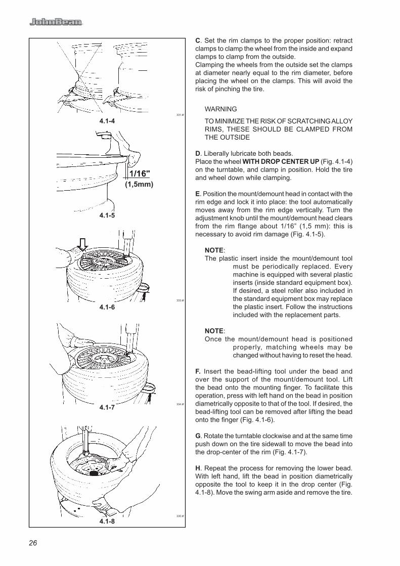
C. Set the rim clamps to the proper position: retract clamps to clamp the wheel from the inside and expand clamps to clamp from the outside.Clamping the wheels from the outside set the clamps at diameter nearly equal to the rim diameter, before placing the wheel on the clamps. This will avoid the risk of pinching the tire.
WARNING
TO MINIMIZE THE RISK OF SCRATCHING ALLOY RIMS, THESE SHOULD BE CLAMPED FROM THE OUTSIDE
D. Liberally lubricate both beads.Place the wheel WITH DROP CENTER UP (Fig. 4.1-4) on the turntable, and clamp in position. Hold the tire and wheel down while clamping.
E. Position the mount/demount head in contact with the rim edge and lock it into place: the tool automatically moves away from the rim edge vertically. Turn the adjustment knob until the mount/demount head clears from the rim flange about 1/16” (1,5 mm): this is necessary to avoid rim damage (Fig. 4.1-5).
NOTE:The plastic insert inside the mount/demount tool
must be periodically replaced. Every machine is equipped with several plastic inserts (inside standard equipment box). If desired, a steel roller also included in the standard equipment box may replace the plastic insert. Follow the instructions included with the replacement parts.
NOTE:Once the mount/demount head is positioned
properly, matching wheels may be changed without having to reset the head.
F. Insert the bead-lifting tool under the bead and over the support of the mount/demount tool. Lift the bead onto the mounting fi nger. To facilitate this operation, press with left hand on the bead in position diametrically opposite to that of the tool. If desired, the bead-lifting tool can be removed after lifting the bead onto the fi nger (Fig. 4.1-6).
G. Rotate the turntable clockwise and at the same time push down on the tire sidewall to move the bead into the drop-center of the rim (Fig. 4.1-7).
H. Repeat the process for removing the lower bead. With left hand, lift the bead in position diametrically opposite the tool to keep it in the drop center (Fig. 4.1-8). Move the swing arm aside and remove the tire.

27
C. Positionner les griffes d’une façon convenable: griffes fermées pour bloquer la roue par l’intérieur et griffes ouvertes pour bloquer la roue par l’extérieur. Quand on bloque de l’extérieur des roues, positionner les griffes à un diamètre proche de celui de la jante avant de positionner la roue sur l’autocentreur. Cela évite le risque de pincer l’enveloppe.
AVERTISSEMENT ! BLOQUER LES JANTES EN ALLIAGE PAR L’EXTÉRIEUR POUR RÉDUIRE LE RISQUE D’ENDOMMAGEMENT.
D. Lubrifi er les deux talons.Positionner la roue sur l’autocentreur AVEC LE CREUX DE LA JANTE VERS LE HAUT (Fig. 4.1-4) et la bloquer.Tenir le pneu et la roue pendant le blocage.
E. Mettre l’outil en contact avec le bord de la jante et le bloquer: l’outil s’éloigne automatiquement du bord de la jante en sens vertical. Tourner la poignée de réglage jusqu’à ce que l’outil s’éloigne du bord de la jante à peu près de 1/16” (1,5 mm): celà est nécessaire pour éviter des dommages à la jante (Fig. 4.1-5).
REMARQUE : La pièce intercalaire en plastique a l’intérieur de l’outil de montage/démontage doit être remplacé périodiquement. Chaque machine est fournie de différentes pièces intercalaires de rechange (dans la boîte des accessoires). Si on le désire, la pièce intercalaire en plastique peut être remplacée par une molette en acier contenue dans la boîte des accessoires. Suivre les instructions jointes aux pièces de rechange.
REMARQUE: Quand l’outil de montage/démontage a été correctement positionné, les roues identiques peuvent être montées sans devoir régler l’outil de nouveau.
F. Introduire le levier pour soulever l’enveloppe en-dessous du talon et au-dessus du support de l’outil. Soulever le talon sur la languette de montage. Pour rendre l’opération plus facile, appuyer, de la main gauche, sur le flanc du pneu dans une position opposée à celle de l’outil. Si l’on veut, on peut enlever le levier pour soulever l’enveloppe après avoir soulevé le talon sur la languette de montage (Fig. 4.1-6).
G. Faire tourner l’autocentreur dans le sens des aiguilles d’une montre et en même temps, appuyer sur le fl anc du pneu pour maintenir le talon dans le creux (Fig. 4.1-7).
H. Démonter le deuxième talon en exécutant les mêmes opérations.Soulever le pneu de la main gauche dans une position opposée à l’outil pour maintenir le talon dans le creux (Fig. 4.1-8). Déplacer le bras déporté latéralement et enlever le pneu.

28
4.1.1-5
4.1.1-1
4.1.1-2
4.1.1-3
4.1.1-4
903.tif
899.tif
900.tif
901.tif
902.tif
4.1.1 Use the bead presser as a demounting help device.
A. In order to make the locking of hard or lowered tires easier, the operator can use the rim pusher provided with the bead pusher. Apply the rim pusher (Item 1, Fig.4.1.1-1) on the bead pusher tool (Item 2), position it at the centre of the rim (Fig.4.1.1-1) and low the rim as far as the clamps can lock the rim (Fig.4.1.1-2).
B. Position the roller approx. 2 cm (3/4”) from the rim edge. Press down the sidewall of the tyre to ease the introduction of the tyre bar (Fig. 4.1.1-3). Move the roller to rest position.To facilitate the lift of the bead on the head tool, position the lower disk next to the edge of the lower rim edge, hold fi rmly the arm of the disk and start the lifting of the device (Fig.4.1.1-4).Demount the fi rst bead as described in the tyre changer operator’s manual.
C. Position the lower disk next to the lower rim edge. Hold fi rmly the handle, and at the same time rotate the turntable (Fig. 4.1.1-5). This operation allows loosening the bead if this is stuck and helps lifting the tyre.
NOTE: A certain effort on the handle of the lower disk in radial direction is normal to counter-balance the action of the turntable that pushes the disk off the center when rotating.
THE LOWER DISK DEVICE CANNOT BE LOCKED BECAUSE OF SAFETY REASONS.

29
4.1.1 Utilisation du presse-talon pendant la phase de démontage.
A. Afi n de faciliter le bloquage des roues avec pneus durs ou rabaissés, on pourrait utiliser le presse-jante du presse-talon. Appliquer le presse-jante (pos. 1, Fig.4.1.1-1) sur l’outil presse-talon (pos. 2), le positionner au centre de la jante (Fig.4.1.1-1) et descendre la jante jusqu’à quand l’on permet aux coins de bloquer la jante (Fig.4.1.1-2).
B. Positionner le rouleau à peu près à 2 cm. (3/4”) du bord de la jante. Baisser le fl anc du pneu pour rendre plus facile l’introduction du levier lève-talon (Fig.4.1.1-3). Mettre le rouleau en position de repos.A fi n de faciliter le soulèvement du talon sur la languette de l’outil, positionner le disque près du bord de la jante inférieure, tenir la tige du disque avec fermeté et actionner la monté du dispositif (Fig.4.1.1-4).Démonter le premier talon comme il est décrit dans le manuel d’emploi du démonte-pneu.
C. Positionner le disque inférieur près du bord de la jante inférieur. Tenir solidement la poignée du presse-talon inférieur, faire monter le dispositif en agissant sur le levier et en même temps tourner l’autocentreur (Fig. 4.1.1-5). Cette manoeuvre permet de détacher la talon s’il s’est entalonné de nouveau et aide à soulever l’enveloppe
REMARQUE : Un certain effort en direction radiale sur la poignée du disque inférieur est normal pour faire obstacle à l’action de l’autocentreur qui, à cause de la rotation, tend à pousser le disque vers l’extérieur.
LE DISQUE INFÉRIEUR NE PEUT PAS ÊTRE BLOQUÉ POUR DES MOTIFS DE SÉCURITÉ.

30
4.2-1
4.2-3
4.2-4
4.2.1-1
4.2-2
336.tif
338.tif
905.tif
930.tif
337.tif
4.2 Mounting tubeless tires
A. Lubricate the entire rim surface (Fig. 4.2-1).Lubricate both beads, inside and outside, (Fig. 4.2-2).
WARNING
LIBERAL LUBRICATION OF THE TIRE AND RIM IS NECESSARY TO MOUNT TIRE CENTERING CORRECTLY AND GET A PROPER ON THE RIM. BE SURE YOU ARE USING APPROVED LUBRICANT ONLY.
WARNING
OBSERVE THE ROTATION DIRECTION OF THE TIRE, IF REQUIRED. SOME TIRES HAVE A COLOR DOT THAT MUST BE KEPT ON THE OUTSIDE OF THE WHEEL.
B. Lock the rim on the turntable and rotate it to have the valve in 5 o’clock position. Place the tire to be mounted on the rim. Swing the mounting arm forward so that the mount/demount tool is in the working position. Engage the lower bead OVER the mounting wing and UNDER the mounting fi nger of the mounting tool. Turn the wheel clockwise and push the tire down into the drop center, opposite to the mount/demount head (Fig. 4.2-3).
C. Mount the upper bead following the directions in section B (Fig. 4.2-4). With low profi le tyres the pneumatic bead holding and mounting tool “MH 320 Pro” can help to facilitate mounting of the top bead (Fig. 4.2-4).
4.2.1 Use the bead presser as a mounting help device.
A. Mount the fi rst bead.Position the roller (Item 1) and the bead pusher tool (Item 2) as showed in Fig. 4.2.1-1.
B. Lower the bead pusher so that the roller and the bead pusher tool on the tire help keeping the bead into the drop center (Fig. 4.2-4).The bead pusher tool follows the tire rotation during the mounting operation.Bring the roller and the bead pusher tool back to rest position.

31
4.2 Montage pneus sans chambre (tubeless)
A. Lubrifi er toute la surface de la jante (Fig. 4.2-1).Lubrifi er les deux talons du pneu à l’intérieur et à l’extérieur avec un lubrifi ant pour pneus (Fig. 4.2-2).
AVERTISSEMENT ! UNE LUBRIFICATION ABONDANTE EST NECÉSSAIRE POUR MONTER LE PNEU CORRECTEMENT ET OBTENIR UN BON CENTRAGE SUR LA JANTE. UTILISER SEULEMENT DES LUBRIFIANTS SPÉCIFIQUES POUR PNEUS.
AVERTISSEMENT ! CONTRÔLER LE SENS DE ROTATION DU PNEU S’IL EST IMPOSÉ. CERTAINS PNEUS ONT UN POINT COLORÉ QUI DOIT ÊTRE TENU SUR LE FLANC EXTÉRIEUR DU PNEU
B. Bloquer la jante sur l’autocentreur et la tourner pour avoir la vanne sur 5h. Mettre le pneu sur la jante. Approcher le bras déporté et mettre l’outil en position de travail.Engager le talon inférieur AU-DESSUS de l’ailette de montage et EN-DESSOUS de la languette de l’outil. Faire tourner l’autocentreur dans le sens des aiguilles d’une montre et pousser le talon dans le creux en position opposée à l’outil (Fig.4.2-3)
C. Monter le talon supérieur de la même façon. Pour les pneus taille baisse, utiliser l’outil de montage à actionnement pneumatique ”MH 320 Pro” (Fig. 4.2-4).
4.2.1 Utilisation du presse-talon pendant la phase de montage.
A. Monter le premier talon.Positionner le rouleau (pos. 1) et l’outil presseur (pos. 2) selon l’image 4.2.1-1.
B. Descendre le presse talon de façon que la pression du rouleau et de l’outil presseur sur le pneu aident à garder le talon dans le canal de la jante (Fig. 4.2-4).L’outil presseur suit la rotation du pneu pendant le montage. Porter le rouleau et l’outil presseur en position de repos.

32
4.3-1340a.tif
4.3 Infl ation of tubeless tiresMake sure that both beads are properly lubricated.
WARNING: BEAD SEATING IS THE MOST DANGEROUS PART OF MOUNTING A TIRE.
IT IS POSSIBLE TO MOUNT TIRES THAT ARE 1/2” SMALLER IN DIAMETER THAN THE RIM THEY ARE MOUNTED ON. WHILE THESE BEADS WILL SEAL, IT IS IMPOSSIBLE TO GET THEM TO SEAT IN THEIR PROPER POSITION.
EXPLOSION OF A TIRE MAY CAUSE SEVERE INJURY OR DEATH.
Infl ate tire according to manufacturers recommendations.
WARNINGNEVER EXCEED THE MAXIMUM PRESSURE
ALLOWED BY THE TIRE MANUFACTURER.
For safety reasons a quick-infl ating valve preset to 4,5 bar is fi tted upstream of the pressure gauge for the pedal-operated infl ating device.
THE RIM MUST BE UNCLAMPED WHEN INFLATING BUT ONLY AFTER BEADS HAVE BEEN SEATED.
THE OPERATOR MUST STAND CLEAR FROM THE WHEEL WHEN INFLATING, AND PRESSURE MUST BE MONITORED FREQUENTLY TO AVOID OVER-INFLATION.
BEFORE INFLATING A TIRE, CHECK THE CONDITION OF TIRE AND RIM.Due to unusual confi gurations or the stacking of tires the infl ation process is sometimes diffi cult.To assist with this problem the JBC EHP System V is equipped with bead seater jets incorporated into the tabletop.To utilize the bead seater proceed as follows:
A. If possible lock the wheel from inside. Outside locking reduces effi ciency.
NOTE: Use Light alloy rim protector to prevent any possible damage to the rim when operating on light alloy rims.
B. Connect the infl ation hose to the valve stem.
C. Lift the tire with both hands so that upper bead is sealed to the rim edge (Fig. 4.3-1).
D. Press the infl ation pedal down swiftly. The top bead is already sealed by the lifting motion. The air from the bead seater jets will rebound into the bottom sidewall driving it into place and creating a seal.
ATTENTION!WHEN OPERATING THE BEAD SEATER WEAR SAFETY ATTIRE TO AVOID INJURY TO BODY OR EYES.
E. Complete infl ation as described at §4.3.A.

33
4.3 Gonfl age pneus sans chambre (tubeless)S’assurer que les deux talons soient bien lubrifi és
AVERTISSEMENT ! LA MISE EN PLACE DU TALON EST LA PHASE LA PLUS DANGEREUSE DU MONTAGE D’UN PNEU. IL EST POSSIBLE DE MONTER DES PNEUS DE 1/2” PLUS PETITS QUE LE DIAMÈTRE DE LA JANTE SUR LAQUELLE ILS SONT MONTÉS. MÊME SI LES TALONS S’ACCROCHENT, IL EST IMPOSSIBLE DE RÉUSSIR À LES METTRE EN PLACE DANS LEUR POSITION CORRECTE.
LA CREVAISON D’UN PNEU, POUR N’IMPORTE QUELLE RAISON, PEUT CAUSER DES LÉSIONS GRAVES OU MORTELLES.
Gonfl er le pneu en suivant les instructions du fabricant
AVERTISSEMENT ! EN AUCUN CAS ON NE DEVRA DÉPASSER LA PRESSION MAXIMUM ADMISE PAR
LE CONSTRUCTEUR DU PNEU.
Pour des raisons de sécurité, une soupape à gonfl age rapide préréglée à 4,5 bars est montée en amont du manomètre, pour le dispositif de gonfl age actionné par pédale.
LA JANTE DOIT ÊTRE DEBLOQUÉE LORSQUE L’ON PROCÈDE AU GONFLAGE, MAIS SEULEMENT APRÈSQUE LES TALONS SOIENT MIS EN PLACE.
L’OPÉRATEUR DOIT RESTER À UNE DISTANCE DE SÛRETÉ QUAND LE PNEU EST GONFLÉ ET LA PRESSION DOIT ÊTRE CONTROLÉE FRÉQUEMMENT POUR ÉVITER UN GONFLAGE EXCESSIF.
Le gonfl age peut être rendu diffi cile à cause d’une
forme particulière ou de l’empilement des pneus.
Pour cela la machine JBC EHP System V est équipée
d’injecteurs incorporés dans l’autocentreur.
Pour utiliser le gonfl eur, procéder comme suit:
A. Bloquer la roue sur l’autocentreur par l’intérieur de
préférence (le blocage par l’extérieur réduit l’effi cacité du
dispositif).
REMARQUE : Utiliser les Protections pour jantes en
alliage monte sur les mors de l’autocentreur
pour prévenir tout dommage à la jante
quand on opère sur jantes en alliage léger.
B. Connecter le tuyau de gonfl age à la vanne.
C. Soulever le pneu des deux mains afi n que le talon
supérieur s’accroche contre le bord de la jante (Fig. 4.3-1).
D. Appuyer à fond d’une façon rapide sur la pédale de
gonfl age. Une grande quantité d’air est expulsée par
les injecteurs placés sur les griffes et le talon inférieur
adhère au bord de la jante en permettant le gonfl age.
ATTENTION!PORTER DES LUNETTES ET DES VETEMENTS DE PROTECTION LORSQU’ON UTILISE LE GONFLEUR.
E. Terminer le gonfl age comme décrit au début du
paragraphe §4.3.A.

34
4.4-1
EAA0247G07A
EAA0332G84A
4.4 Mounting and Demounting Motorcycle Tires
To mount and demount motorcycle, motor scooter or ATV tires it is necessary to utilize the optional adaptors (4 piece EAA0247G07A or EAA0332G84A) and the small-wheel bead breaker blade.The bead breaking, mounting and demounting technique is the same as per car tires.
NOTE: If the top tire bead is diffi cult to mount, see paragraph 4.2.1.
WARNING!MOTORCYCLE RIMS MUST ALWAYS BE CLAMPED FROM THE OUTSIDE.
4.5 Angular tool adjustment
The tool is adjusted at the factory with an optimal angle for most wheels used today. However, the angle can be optimised for wheels with a diameter that differs considerably from the standard.
To adjust the tool angle, proceed as follows:
1. Mount the rim for which the adjustment is required.
2. Loosen the lower screw (1, Fig. 4.4-1).
3. Adjust the tool with the screws shown (2a and 2b, Fig. 4.4-1). Unscrew the screw (2a or 2b, Fig. 4.4-1) to rotate the tool, respectively clockwise or counterclockwise.
4. Screw in the opposite screw to block the tool in the desired angular position.
5. Tighten the lower screw (1, Fig. 4.4-1) with a torque of 35 Nm.

35
4.4 Montage et Démontage Pneus MotoPour opérer sur les pneus pour motocyclette, moto-scooters/ATV il faut monter les adaptateurs à prise rapide sur les griffes de l’autocentreur (4 pièces EAA0247G07A ou EAA0332G84A) et la petite Palette Detalloneur.La technique de détalonnage, de montage et de démontage est la même que pour les pneus pour auto.
REMARQUE :En cas de diffi cultés pour le montage du talon supérieur suivre les instructions données au chapitre 4.2.1.
ATTENTIONLES JANTES MOTO DOIVENT ÊTRE BLOQUÉES TOUJOURS PAR L’EXTÉRIEUR.
4.5 Réglage angulaire de l’outil
L’outil se règle à l’origine avec un angle optimal pour la plupart des roues actuelles. L’angle peut toutefois être optimisé pour des roues de diamètre sensiblement différent de la moyenne.
Pour régler l’angle de l’outil, procéder de la façon suivante :
1. Monter la jante dont lla fonctionnalité doit être optimisée
2. Desserrer la vis inférieure (1, Fig. 4.4-1).
3. Régler l’outil à l’aide des vis représentées en (2a et 2b, Fig. 4.4-1). Dévisser la vis (2a ou 2b, Fig. 4.4-1) pour tourner l’outil respectivement en sens horaire ou antihoraire.
4. Visser la vis opposée pour bloquer l’outil en position angulaire souhaitée.
5. Serrer la vis inférieur (1, Fig. 4.4-1) au couple de 35 Nm.

36
5.2-1
5.1-1
5.1-2
5.1-3
537.tif
341.tif
342.tif
343.tif
5.1 Mounting tube-type tires
A. Proceed as described in section 4.2.A.Do NOT lubricate the tube. Talc can be used to assist with the tube positioning.
B. Mount the valve core and place the tube onto the tire to confi rm that the tube is of the correct size (Fig. 5.1-1).
C. Infl ate the tube slightly: if held with the index fi nger it should bend a little (Fig. 5.1-2).
D. Mount the fi rst bead as described in section 4.2.B.Put the tube inside the tire and secure the valve with the chuck of the infl ating hose (Fig. 5.1-3).Mount the top bead following the directions above.
5.2 Infl ating tube-type tiresTo infl ate the tires unlock the rim and start infl ating while pressing the valve towards the inside. This is necessary to avoid air pockets forming between tube and tire (Fig. 5.2-1).Ensure that the tire is correctly centered on the rim and complete infl ation as described in section 4.3.
5.0 Demounting tube-type tires
A. For breaking the bead operate as described for the tubeless tires in § 4.1.A to 4.1.F.
In this case, the valve is part of the tube
WARNING: BE CAREFUL NOT TO DAMAGE THE TUBE DURING THE BEAD-BREAKING OPERATION. THE VALVE SHOULD BE OPPOSITE TO THE BLADE OF THE BEAD BREAKER.
NOTE: In order to avoid damage to their surface fi nish, alloy rims should be clamped from the outside only.
Special plastic caps are available as optional extras for the clamping jaws so that alloy rims can be clamped carefully.
B. To demount the fi rst bead, place the valve at 3 o’clock position.
WARNING
DO NOT CATCH THE TUBE WITH THE BEAD LIFTING TOOL, WHEN LIFTING THE BEAD ON THE MOUNTING FINGER
After demounting the fi rst bead remove the tube before demounting the second bead, as described in section 4.1.

37
5.1 Montage pneus avec chambre
A. Opérer comme décrit au § 4.2.A.NE PAS lubrifi er la chambre à air. Si on le désire, utiliser de la poudre de talc pour faciliter le positionnement de la chambre à air dans le pneu
B. Monter la vanne sur la chambre à air et l’appuyer sur l’enveloppe pour contrôler si la mesure est correcte (Fig. 5.1-1).
C. Gonfl er un peu la chambre à air: si on la soutient de l’index elle doit se plier un peu (Fig. 5.1-2).
D. Monter le premier talon comme décrit au §4.2.B. Mettre la chambre à air dans le pneu et accrocher la vanne avec la pince du tuyau de gonfl age (Fig. 5.1-3). Monter le deuxième talon comme le premier.
5.2 Gonfl age pneus avec chambreDébloquer la jante et commencer à gonfl er le pneu en poussant la vanne vers l’intérieur pour éviter la formation de poches d’air entre la chambre à air et l’enveloppe (Fig. 5.2-1).Contrôler si le pneu est bien centré sur la jante et terminer le gonfl age comme décrit au § 4.3.
5.0 Démontage pneus avec chambre
A. Pour le démontage opérer comme décrit pour les pneus sans chambre au § 4.1 A to 4.1.F.
Dans ce cas la vanne ne peut pas être remplacée car elle est unie à la chambre à air.
AVERTISSEMENT ! NE PAS ENDOMMAGER LA CHAMBRE À AIR PENDANT L’OPÉRATION DE DÉTALONNAGE. LA VANNE DOIT ÊTRE EN POSITION OPPOSÉE À LA PALETTE DU DÉTALONNEUR.
REMARQUE : Afi n d’éviter tout endommagement de leur surface, les jantes en alliage léger sont serrées uniquement de l’extérieur.
Des capuchons spéciaux en matière plastique sont disponibles en option pour les mors de serrage afi n que les jantes en alliage léger puissent être serrées sans être endommagées.
B. Pour démonter le premier talon, la vanne devra être positionnée sur 3h.
AVERTISSEMENT ! NE PAS PINCER LA CHAMBRE À AIR AVEC LE LEVIER QUAND ON SOULÈVE LE TALON SUR LA LANGUETTE DE L’OUTIL.
Après avoir démonté le premier talon, enlever la chambre à air avant de démonter le deuxième talon, comme décrit au § 4.1.

38
6.0-1
6.0-2
6.0-31059.tif
XXXX.tif
B
C
A
67
5
8
6.0 maintenance
WARNINGBEFORE ATTEMPING ANY MAINTENANCE OR REPAIRS THE MACHINE MUST BE DISCONNECTED FROM THE AIR AND ELECTRIC SUPPLY.
A. Periodically clean the vertical hexagonal rod with nonfl ammable liquid detergent. Lubricate with oil (Fig. 5.4).
B. Periodically clean all moving metal parts and lubricate with oil.
C. Clean the teeth of the clamps with a wire brush, check the plastic rim protectors and replace if worn (Fig. 5.5).
D. Peridically replaced the plastic insert inside mount/demount tool.
E. Lubricate rods of air cylinders with oil as needed.
F. Periodically wash all plastic parts with cold water and soap or window cleaner.
G. Check the bead breaker pads. Replace if worn.
H. Discharge the water every day from air fi lter. Do this by pulling down the fi tting ‘B’ (Fig. 6.0-3).
I. The machine is equipped with an automatic lubricator. Check the oil level weekly.When adding oil to the lubricator, disconnect the air supply fi rst, remove the cup ‘A’, and add oil as needed. Make sure seals are in place when repositioning the cup
L. Check oil dosage: After operating the pedals (6 e 8, Fig. 6.0-3) 2 - 3 times, one drop of oil should fall into the sight glass. If necessary adjust using the dosing screw (C, Fig. 6.0-3).
WARNING! PAY ATTENTION TO KEEP FILLED THE OIL TANK OF THE OILER, EXPECIALLY FOR AIR MOTOR OPERATED MACHINES.
WARNING! USE ONLY OILS FOR AIR DEVICES, DO NOT USE BRAKE FLUID OR OTHER NOT SUGGESTED LUBRICANTS.
Suggested oils for the fi lter/lubricator unit:
TAMOIL: WHITE MINERAL OIL 15SHELL: ONDINA OIL 15BP: ENERGOL WT 3TOTAL: LOBELIA SB 15ESSO: MARCOL 82

39
6.0 Entretien
AVERTISSEMENT ! AVANT DE COMMENCER TOUTE OPÉRATION D’ENTRETIEN ET DE RÉPARATION DÉBRANCHER LA MACHINE DU RÉSEAU ÉLECTRIQUE ET DE L’AIR COMPRIMÉ.
A. Nettoyer périodiquement la tige hexagonale avec un détergent liquide non infl ammable. Lubrifi er avec de l’huile (Fig. 5.4).
B. Nettoyer périodiquement toutes les parties métalliques en mouvement et lubrifi er.
C. Nettoyer avec une brosse en acier les dents des griffes et contrôler les protections en plastique: si celles-ci sont détériorées les remplacer avec de nouvelles protections (Fig. 5.5).
D. Remplacer périodiquement les parties en plastique dans l’outil de montage/démontage.
E. Lubrifi er les manchons des cylindres pneumatiques si nécessaire.
F. Laver périodiquement toutes les parties en plastique à l’eau froide et savon ou avec du produit pour les vitres.
G. Contrôler les supports du détalonneur et remplace si nécessaire.
H. Vider l’eau du fi ltre à air tous les jours en tirant la décharge rapide ‘B’ vers le bas (Fig. 6.0-3).
I. La machine est équipée d’un huileur automatique, contrôler régulièrement le niveau de l’huile. Quand on ajoute de l’huile, il faut tout d’abord debrancher le réseau de l’air comprimé, enlever ensuite le reservoir ‘A’ et ajouter de l’huile en quantité suffi sante. S’assurer que les joints soient en position quand monté de noveau.
L. Vérifi er le dosage de l’huile. Après avoir actionné les pédales (6 e 8, Fig. 6.0-3) deux à trois coups, une gotte d’huile doit tomber dans le verre indicateur; sinon, régler la vis de dosage (C, Fig. 6.0-3).
AVERTISSEMENT ! MAINTENIR HAUT LE NIVEAU DU HUILEUR, EN PARTICULIER POUR LES MACHINES ACTIONEES D’UN MOTEUR PNEUMATIQUE.
AVERTISSEMENT ! UTILISER EXCLUSIVEMENT DES HUILES POUR DISPOSITIFS PNEUMATIQUES, NE PAS UTILISER DE LIQUIDE POUR FREINS OU D’AUTRE LUBRIFIANTS NON CONSEILLÉS.
Huiles conseillées pour fi ltre/ huileur :
TAMOIL: WHITE MINERAL OIL 15SHELL: ONDINA OIL 15BP: ENERGOL WT 3TOTAL: LOBELIA SB 15ESSO: MARCOL 82

40
7.0 Putting the machine out of service
In case the machine is not be used for a long period of time (6 months or more) it is necessary to disconnect air and power service, discharge the bead seater tank (if provided), protect all parts that may be damaged from environmental intrusion, protect the air hoses that may be damaged by the drying process.
When putting the machine back in operation, check the con-dition of all previously protected parts, and check for correct functioning of all devices before using the machine again.
8.0 Disposing of the unitTo dispose of the equipment at the end of its life, contact the reseller for a quote or for the regulations on disposal which apply to the unit.
This symbol indicates that separate collection of waste electrical and electronic equipment is mandatory for scrapping.
8.1 Instructions for disposalFor electrical and electronic equipment European directive 2002/95/EC, 2002/96/CE and 2003/108/EC (RAEE)
At the time of disposal, at the end of the lifetime of this equipment, you must:
1. Render the machine inoperative, remove the plug and cut off the power supply cable close to where it comes out of the machine.
2. DO NOT dispose of the equipment as urban waste and recycle it, by taking the materials to suitable recycling centres.
3. Contact the reseller for the closest authorised recycling centres for the disposal or for the collection of old equipment when purchasing new equipment.
4. Stick to the standards for correct waste management, to prevent potential effects on the environment and human health. Unauthorised disposal will result in administrative sanctions for the offenders.

41
7.0 Mise de côté
En cas de mise de côté de la machine pendant longtemps (6 mois) il est nécessaire de déconnecter les sources d’alimentation, de vider le réservoir, de protéger toutes les pièces qui pourraient être endommagées, de protèger les tuyaux pneumatiques qui pourraient être endommagés par le séchage.Si l’on utilise à nouveau la machine, contrôler l’état des parties précedemment protégées et effectuer un premier essai avant de remettre la machine en fonction.
8.0 VentePour la mise à la décharge de l’équipement arrivé en fi n de vie, contacter le revendeur pour une offre ou pour connaître les instructions utiles à son démantèlement.
Ce symbole indique l’obligation d’effectuer le tri sélectif des appareils électriques et électroniques au moment de sa mise à la décharge.
8.1 Consignes de démolitionPour les équipements électriques et électroniques, voir la Directive européenne 2002/95/CE, 2002/96/CE et 2003/108/CE (RAEE)
Au moment de la mise à la décharge, à la fi n de la vie de cet équipement, il est obligatoire de :
1. Mettre la machine hors service ; ôter la fi che et couper le câble d’alimentation à proximité de sa sortie de la machine.
2. NE PAS SE DÉFAIRE de l’équipement comme s’il s’agissait d’un déchet urbain mais effectuer le tri sélectif en apportant les matériaux aux centres de collecte et de tri agréés.
3. S’informer auprès du revendeur pour connaître les endroits de collecte, de recyclage et de tri autorisés ou pour une éventuelle reprise de l’équipement en cas d’achat d’un neuf (obligation du « un pour un »).
4. Respecter les normes sur la gestion des déchets pour éviter tout risque probable de nuisances à l’environnement et à la santé des personnes. En cas de mise à la décharge illicite, le transgresseur est passible de sanctions administratives.

42
B L A N K P A G E

43
B L A N K P A G E

GB
FR
ES
309 Exchange Ave.Conway, AR 72032Ph: 501-450-1500Fax: 501-450-2085
This document contains proprietary information which is protected by copyright and patents. All rights are reserved.No part of this document may be photocopied, reproduced, or translated without prior written consent of Snapon Equipment.
Notice: The information contained in this document is subject to change without notice. Snap-on Equipment makes no warranty with regard to present documentation. Snap-on Equipment shall not be liable for errors contained herein or for incidental consequential damages in connection with furnishings, performance, or use of this material.
SO
E D
igita
l C
od
e: O
M_
JB E
HP
SY
S-V
_1
8-1
0_
EN
-FR
-ES
_G
1_
ZE
EW
H5
17A
03
EN
FR
ES
309 Exchange Ave.Conway, AR 72032Ph: 501-450-1500Fax: 501-450-2085
This document contains proprietary information which is protected by copyright and patents. All rights are reserved.No part of this document may be photocopied, reproduced, or translated without prior written consent of Snapon Equipment.
Notice: The information contained in this document is subject to change without notice. Snap-on Equipment makes no warranty with regard to present documentation. Snap-on Equipment shall not be liable for errors contained herein or for incidental consequential damages in connection with furnishings, performance, or use of this material.