eg dc kswap mount kit install guide
TRANSCRIPT
1
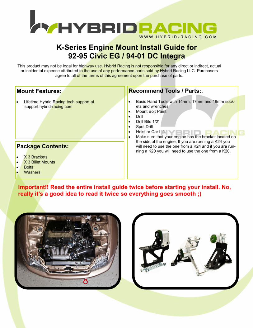
K-Series Engine Mount Install Guide for 92-95 Civic EG / 94-01 DC Integra
Mount Features:
Lifetime Hybrid Racing tech support at support.hybrid-racing.com
Package Contents:
X 3 Brackets
X 3 Billet Mounts
Bolts
Washers
This product may not be legal for highway use. Hybrid Racing is not responsible for any direct or indirect, actual or incidental expense attributed to the use of any performance parts sold by Hybrid Racing LLC. Purchasers
agree to all of the terms of this agreement upon the purchase of parts.
Important!! Read the entire install guide twice before starting your install. No, really it’s a good idea to read it twice so everything goes smooth ;)
Recommend Tools / Parts:.
Basic Hand Tools with 14mm, 17mm and 19mm sock-ets and wrenches.
Mount Bolt Paint
Drill
Drill Bits 1/2”
Spot Drill
Hoist or Car Lift
Make sure that your engine has the bracket located on the side of the engine. If you are running a K24 you will need to use the one from a K24 and if you are run-ning a K20 you will need to use the one from a K20.
2
Install Guide
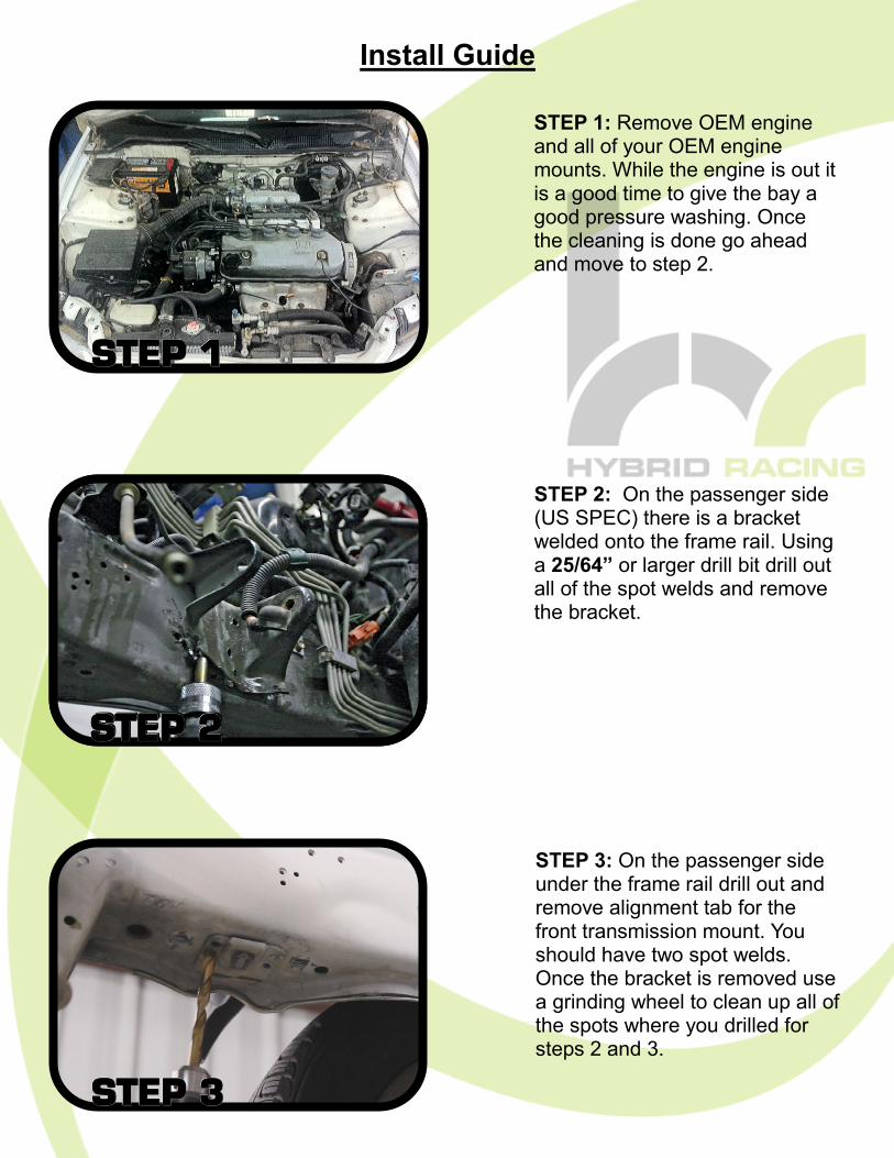
STEP 1: Remove OEM engine and all of your OEM engine mounts. While the engine is out it is a good time to give the bay a good pressure washing. Once the cleaning is done go ahead and move to step 2.
STEP 2: On the passenger side (US SPEC) there is a bracket welded onto the frame rail. Using a 25/64” or larger drill bit drill out all of the spot welds and remove the bracket.
STEP 3: On the passenger side under the frame rail drill out and remove alignment tab for the front transmission mount. You should have two spot welds. Once the bracket is removed use a grinding wheel to clean up all of the spots where you drilled for steps 2 and 3.
STEP STEP STEP 333
STEP 2
STEP STEP STEP 111
STEP STEP STEP 222
3
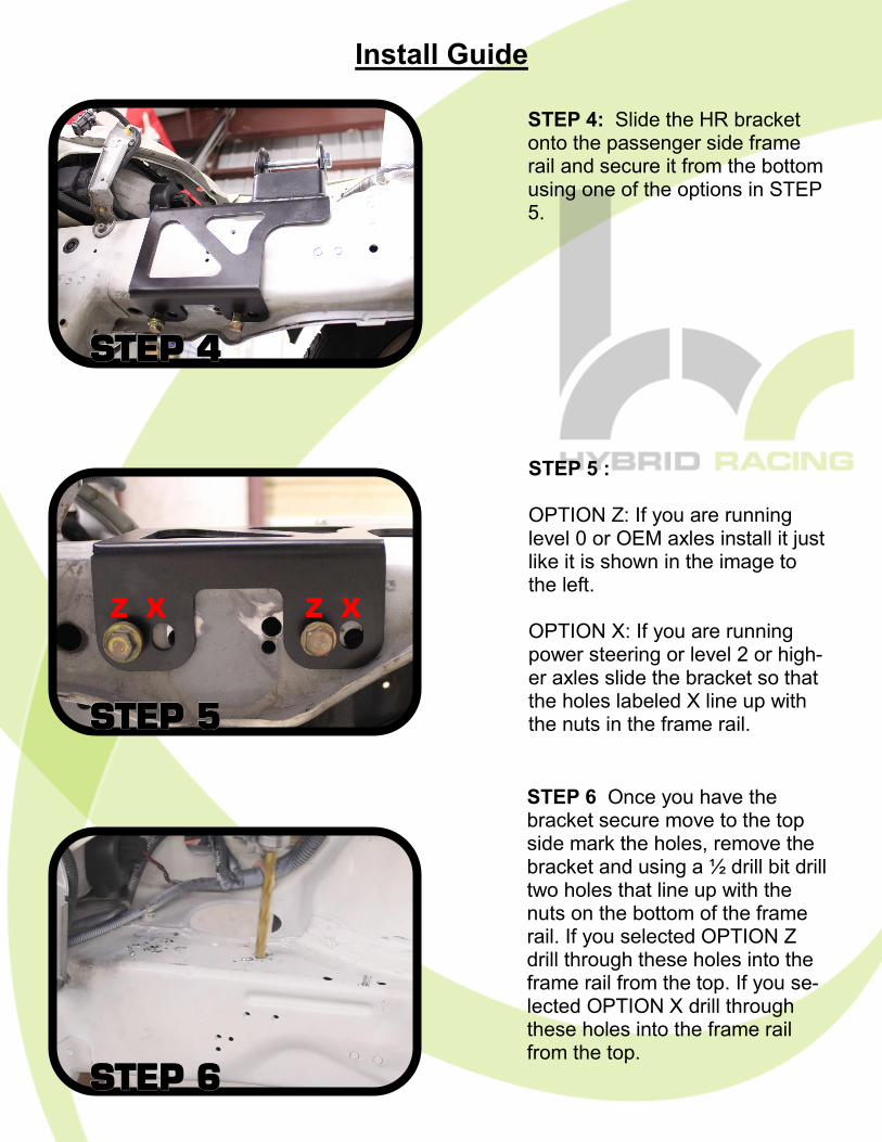
STEP 6 Once you have the bracket secure move to the top side mark the holes, remove the bracket and using a ½ drill bit drill two holes that line up with the nuts on the bottom of the frame rail. If you selected OPTION Z drill through these holes into the frame rail from the top. If you se-lected OPTION X drill through these holes into the frame rail from the top.
STEP 5 : OPTION Z: If you are running level 0 or OEM axles install it just like it is shown in the image to the left. OPTION X: If you are running power steering or level 2 or high-er axles slide the bracket so that the holes labeled X line up with the nuts in the frame rail.
Install Guide
STEP STEP STEP 666
STEP STEP STEP 555
STEP STEP STEP 444
STEP 4: Slide the HR bracket onto the passenger side frame rail and secure it from the bottom using one of the options in STEP 5.
Z X Z X
4
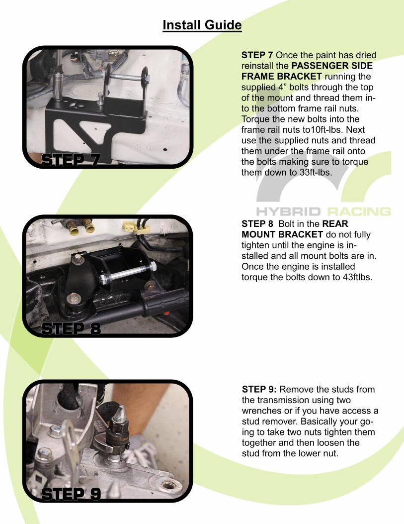
STEP 7 Once the paint has dried reinstall the PASSENGER SIDE FRAME BRACKET running the supplied 4” bolts through the top of the mount and thread them in-to the bottom frame rail nuts. Torque the new bolts into the frame rail nuts to10ft-lbs. Next use the supplied nuts and thread them under the frame rail onto the bolts making sure to torque them down to 33ft-lbs.
Install Guide
STEP 9: Remove the studs from the transmission using two wrenches or if you have access a stud remover. Basically your go-ing to take two nuts tighten them together and then loosen the stud from the lower nut.
STEP STEP STEP 999
STEP STEP STEP 888
STEP STEP STEP 777
STEP 8 Bolt in the REAR MOUNT BRACKET do not fully tighten until the engine is in-stalled and all mount bolts are in. Once the engine is installed torque the bolts down to 43ftlbs.
5
Install Guide
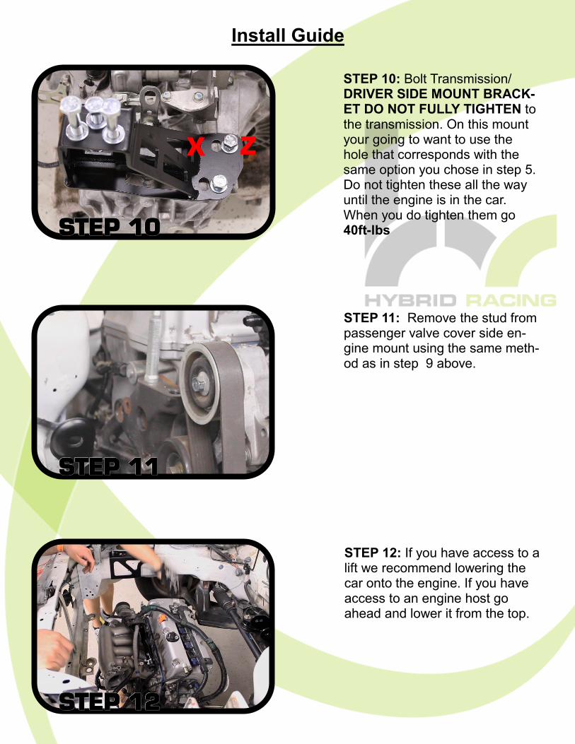
STEP 10: Bolt Transmission/DRIVER SIDE MOUNT BRACK-ET DO NOT FULLY TIGHTEN to the transmission. On this mount your going to want to use the hole that corresponds with the same option you chose in step 5. Do not tighten these all the way until the engine is in the car. When you do tighten them go 40ft-lbs
STEP 12: If you have access to a lift we recommend lowering the car onto the engine. If you have access to an engine host go ahead and lower it from the top.
STEP STEP STEP 121212
STEP 1STEP 1STEP 1111
STEP STEP STEP 101010
STEP 11: Remove the stud from passenger valve cover side en-gine mount using the same meth-od as in step 9 above.
Z X
6
Install Guide
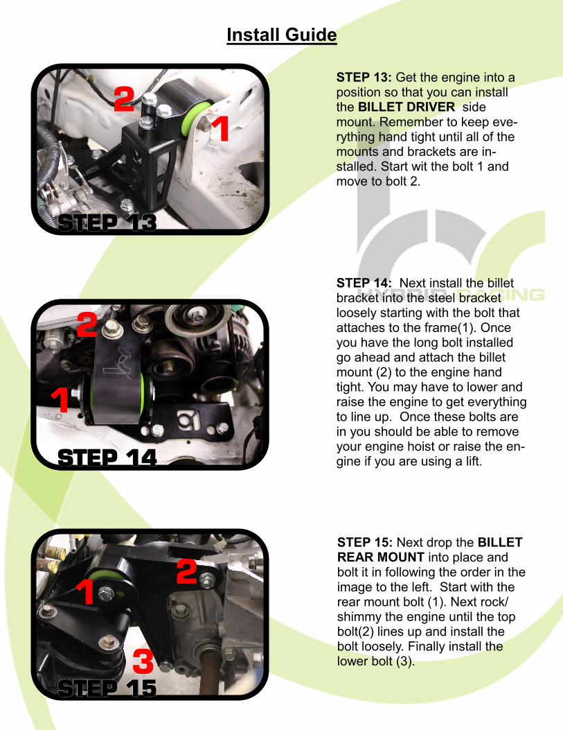
STEP 13: Get the engine into a position so that you can install the BILLET DRIVER side mount. Remember to keep eve-rything hand tight until all of the mounts and brackets are in-stalled. Start wit the bolt 1 and move to bolt 2.
STEP 14: Next install the billet bracket into the steel bracket loosely starting with the bolt that attaches to the frame(1). Once you have the long bolt installed go ahead and attach the billet mount (2) to the engine hand tight. You may have to lower and raise the engine to get everything to line up. Once these bolts are in you should be able to remove your engine hoist or raise the en-gine if you are using a lift.
STEP 15: Next drop the BILLET REAR MOUNT into place and bolt it in following the order in the image to the left. Start with the rear mount bolt (1). Next rock/shimmy the engine until the top bolt(2) lines up and install the bolt loosely. Finally install the lower bolt (3).
STEP STEP STEP 151515
STEP STEP STEP 141414
STEP STEP STEP 131313
1 2
3
1
2
2 1
7
Install Guide
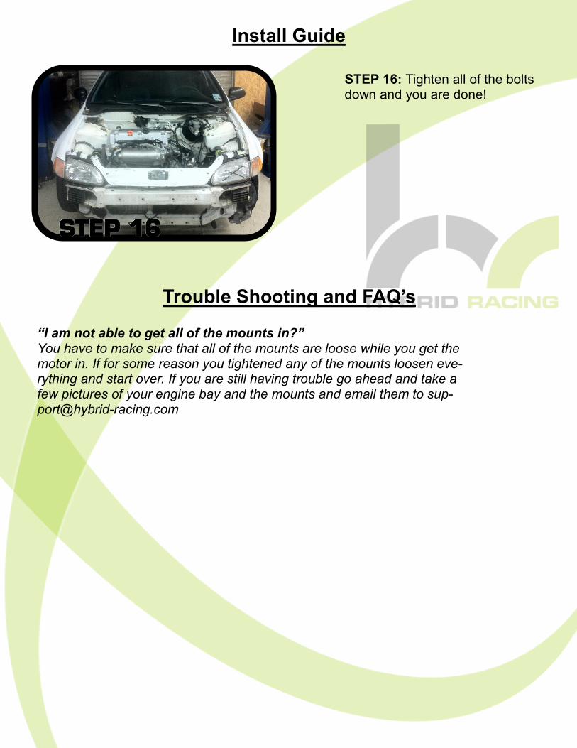
STEP 16: Tighten all of the bolts down and you are done!
STEP STEP STEP 161616
“I am not able to get all of the mounts in?” You have to make sure that all of the mounts are loose while you get the motor in. If for some reason you tightened any of the mounts loosen eve-rything and start over. If you are still having trouble go ahead and take a few pictures of your engine bay and the mounts and email them to [email protected]
Trouble Shooting and FAQ’s
8
If you have any questions or comments, please email support at [email protected]
Legal Disclaimer
Users assume all cost and risk associated with these or any other items purchased from Hybrid Racing LLC. Parts sold or manufactured by Hybrid Racing LLC may not meet legal requirements for use on public roads. People thinking about purchasing product(s) from Hybrid Racing LLC should check with their local and state authorities for legality. It is the user’s re-sponsibility to know and comply with all local and federal laws and regulations. Use or installation of Hybrid Racing LLC products may affect user insurance and/or vehicle warranty coverage. It is the user’s sole responsibility for consequences that may occur due to having the product installed in his/her vehicle. Hybrid Racing LLC assumes no legal responsibilities and/or liabilities, whether to us-er’s vehicle, engine, person(s), and/or property(s), that result from the use of, or servic-ing of a vehicle of which a Hybrid Racing LLC product has been installed/attempted to be installed, or to any other vehicle(s) and/or person(s), regardless of whether or not this product has any involvement directly or indirectly and/or liability, and/or whether or not proper installation has been carried forth. All engines, engine parts and electrical components are for OFF ROAD USE ONLY/RACING VEHICLES ONLY. They are not for or to be used on public roads in the USA. Acquisition of a Hybrid Racing LLC product will act as an acknowledgement of the le-gal disclaimer stated herein. Hybrid Racing LLC reserves the right to change this disclaimer at any time without any prior consent or notification.
Should you need to contact us our details are as follows: Hybrid Racing LLC, 12231 Industriplex Suite B, Baton Rouge, LA 70809
www.hybrid-racing.com