effects of annular combustor width on the ethylene-air
TRANSCRIPT

Research ArticleEffects of Annular Combustor Width on the Ethylene-AirContinuous Rotating Detonation
Weijie Fan, Shijie Liu , Jin Zhou, Haoyang Peng, and Siyuan Huang
Science and Technology on Scramjet Laboratory, College of Aerospace Science and Technology, National University ofDefense Technology, Changsha, Hunan 410073, China
Correspondence should be addressed to Shijie Liu; [email protected]
Received 13 July 2020; Revised 21 August 2020; Accepted 25 August 2020; Published 14 September 2020
Academic Editor: Jing-Lei Xu
Copyright © 2020 Weijie Fan et al. This is an open access article distributed under the Creative Commons Attribution License,which permits unrestricted use, distribution, and reproduction in any medium, provided the original work is properly cited.
The realization and stable operation of Continuous Rotating Detonation (CRD) in the annular combustor fueled by hydrocarbon-air are still challenging. For further investigation of this issue, a series of ethylene-air CRD tests with the variation of combustorwidth is conducted, and the effects of combustor width are well analyzed based on high-frequency pressure and high-speedphotograph images. The results show that the combustor width plays a significant role in the realization and sustainability of theethylene-air CRD. In this paper, the critical combustor width for the CRD realization and stable single wave are 20mm and25mm, respectively. In wide combustors, the backward-facing step at the combustor forepart makes the main flow slow down,and thus, the mixing quality is promoted. Besides, the pilot flame at the recirculation zone contributes to sustaining the CRDwave. As the width increases, the propagation mode changes from counter-rotating two-wave mode to single wave mode withhigher propagation velocity and stability. The highest propagation velocity reaches 1325.56m/s in the 40mm wide combustor,accounting for 71.51% of the corresponding Chapman-Jouguet velocity. Despite large combustor volume, high combustorpressure is obtained in detonation combustion mode indicating that a better propulsive performance could be achieved by CRD.
1. Introduction
Conventional aerospace propulsive systems, such as rocketengine, turbojet engine, ramjet, and scramjet, generally workin the form of isobaric combustion. Isobaric combustion hasbeen deeply studied, and its propulsive performance hasgradually approached the upper limit of the theoretical value.Compared with isobaric combustion, detonation is a promis-ing combustion form that may achieve a better propulsiveperformance, because of its higher thermodynamic efficiencyand faster heat release rate [1, 2]. Generally, detonationengines can be classified as Pulse Detonation Engine (PDE)[3], Oblique Detonation Engine (ODE) [4], and ContinuousRotating Detonation Engine (CRDE) [5, 6]. Additionally,CRDEs do not require repeated ignition. Therefore, CRDEhas attracted great attention in the propulsion research field[7–13]. In CRDE, fuel and oxidizer are usually injected atthe head of the annular combustor, and the CRD wave prop-agates circumferentially consuming the combustible propel-
lant. Then, the combustion products exhaust at the otherend of the combustor and produce a stable thrust.
In 1959, stationary detonation was first proposed byVoitsekhovskii, and the author realized C2H2-O2 CRD ina disk-shaped experimental device [14]. Nicholls et al.[15] experimentally investigated the feasibility of CRDEand realized short CRD in an annular combustor. However,there were only a few researches on CRDE for decades. Inthe past decade, CRDE gradually came under the spotlightagain and aroused great interests of many researchers.Extensive CRD investigations fueled by hydrogen werecarried out due to the low realization difficulty. And theoperation processes of CRDE were studied, including initi-ation [16–18], propagation characteristics [5, 6, 19], andpropulsive performance [12, 20].
Although hydrogen CRD can be easily obtained in a wideoperating range, hydrocarbon fuel, especially kerosene [21–23], is considered as a more reliable and affordable optionfor engineering application. As a main component of kerosene
HindawiInternational Journal of Aerospace EngineeringVolume 2020, Article ID 8863691, 12 pageshttps://doi.org/10.1155/2020/8863691

pyrolysis products, ethylene is one of the real fuels for CRDEwith regenerative cooling technology. Researches on ethyleneCRD can provide a basic understanding of hydrocarbonCRD. However, stable operation of ethylene-air CRD with alow velocity deficit in the annular combustor is still anunsolved problem. Cho et al. [24] carried out a series ofexperiments on ethylene-air CRD in the optically accessibleannular combustor. The propellant was nearly stoichiometricwhile the propagation velocity was only 994 ± 43m/s incounter-rotating two-wave mode. St. George et al. [25] per-formed ethylene-air CRD experiment in the 7.6mm wideannular combustor. However, the CRD wave propagated atthe highest velocity of 850m/s with severe instability and agreat velocity deficit. Andrus et al. [26] experimentally stud-ied ethylene-air CRD using both nonpremixed and premixedsupplying schemes in the 23mm wide annular combustor.The CRD wave propagation velocity was close to CEA pre-dicted sound speed around 1000m/s, which was significantlylower than the C-J velocity. Wilhite et al. [27] conductedethylene-air CRD experiment in the annular combustor witha 13.1mm wide channel. The CRD wave propagated in thevelocity close to isobaric sound speed, and a great velocitydeficit occurred. The detonation of hydrocarbon in the annu-lar combustor needs further study.
For now, new combustor configurations of CRDE areproposed to enhance hydrocarbon CRD, including hollowcombustor and cavity-based annular combustor. Peng et al.[28] performed the ethylene CRD in the optical accessibleracetrack-like combustor with oxygen-enriched air. TheCRD wave propagated in single wave mode with relativelyhigh velocity at 1647.92m/s. Furthermore, Peng et al. [29]achieved ethylene-air CRD with large operating range andlow velocity deficit in the hollow combustor with a Laval noz-zle. The highest propagation velocity reached 1915.4m/s insingle wave mode. Anand et al. [30] successfully obtainedethylene-air CRD in the hollow combustor, and the wavepropagation velocity accounted for 95% of the ideal C-J det-onation velocity. Wang et al. [31] also realized ethylene-airCRD in the hollow combustor with an outer diameter of100mm. The detonation velocities were between 1256 and1653m/s, most of which were above 80% of the C-J detona-tion velocity. Hollow combustor indeed conduces to the real-ization of ethylene CRD. However, inefficient propulsiveperformance of CRD in the hollow combustor was reported[20, 32]. Due to low pressure in the combustor, the specificimpulses were below 80% of the ideal expansion value in
the study of Kawasaki et al. [32]. Cavity-based annular com-bustor is a new configuration proposed by the group ofPeng [33–35]. By applying the cavity to annular combustor,the CRD wave propagation velocity could reach 1228.68m/saround stoichiometric equivalence ratio (ER) accounting for67.4% of the corresponding C-J velocity. The recirculationzone of the cavity had great effects on the CRD and couldchange the CRD propagation mode. It is suggested thatthe proper combustor is indeed conducive to the self-sustaining of CRD wave, and which combustor geometryis the main key factor to stable CRD operation deserves fur-ther investigation.
Hollow combustor can be considered as a special config-uration of annular combustor, in which the inner cylinder isremoved and the combustor width enlarge significantly.Although the combustor width was considered to play akey role in the hydrocarbon CRD [36], the realization andstable operation of the hydrocarbon CRD in the enlargedannular combustor have not been achieved. Thus, the transi-tion from annular combustor to hollow combustor on thevariation of combustor width deserves to be further investi-gated. In this paper, a series of tests fueled by ethylene-airhave been experimentally conducted. The operating rangeand propagation characteristics are summarized. Three com-bustion modes are analyzed through the time-averaged andhigh-frequency pressure results. In addition, the flowfieldsare captured by high-speed photograph camera. This studywill reveal the effects of annular combustor width on theethylene-air CRD and improve the combustor design theoryof CRD fueled by hydrocarbon fuels.
2. Experimental System
The schematic of the annular combustor is shown inFigure 1. The length and the outer diameter of the annularcombustor are 230mm and 130mm, respectively. The com-bustion products are directly discharged into the atmo-sphere at the exit. To investigate the effects of width, theinner diameters of the annular combustor decrease from100mm to 50mm at the interval of 10mm in this paper. Sothat six widths of the annular combustor vary from 15mmto 40mm at the interval of 5mm, labeled as W-15, 20, 25,30, 35, and 40. Ambient-temperature air is supplied throughan annular convergent-divergent slit with a 1.2mm widethroat. And ambient-temperature ethylene is injected intothe combustor through 120 injectors, which are uniformly
100 mm
190 mmAnnular combustorIsolator
Fuel
Engineair
Window upstreamleading edge
Maxwellsensors
PCB2_90deg
Quartz windowView section Axial section
PCB1_0degQuartz window
65 mm
30 mm
Rin
Rout
Figure 1: Schematic diagrams of test section and sensor installation.
2 International Journal of Aerospace Engineering

distributed over the inner circumference with a diameter of0.5mm. Stable mass flow is provided by sonic injectorsinstalled in the feeding lines. The accurate mass flow rate ismeasured by turbine flow meters, whose measurement erroris within 1%.
The time-averaged and high-frequency pressure mea-surements are adopted in this paper, which were verified inprevious studies [33–35]. The time-averaged pressures inthe combustor are acquired by piezo-resistance sensors(Maxwell, Model MPM480). The measurement frequencyof the sensor is 500Hz, and its error is within 0.5% full scale(FS). Eleven sensors (P1-P11) are uniformly installed alongthe axial direction with an interval of 20mm, and the firstsensor P1 is located at the throat of the air injection slit.The high-frequency pressures in the combustor are obtainedby two piezoelectric sensors (PCB113B24) with the NI mea-sure system. The NI measure system samples the dynamicpressure with a 0.5μs interval. The PCB sensor has a resolu-tion of 35Pa and a rise time of less than 2.0μs with a mea-surement range of 6895Pa. The two PCB sensors areinstalled in the same axial cross-section, which is 40mmdownflow away from the throat of the air injection slit. Thereis a circumferential angle of 90° between the two PCB sen-sors. The details of the sensor installation are also displayedin Figure 1.
The time sequence used in this paper is shown inFigure 2. The air and ethylene are turned on in sequence.Then, the hydrogen and oxygen are injected into the hottube. Afterwards, the mixture of hydrogen and oxygen isignited by a spark plug in the hot tube. Later, the CRD waveis initiated by the detonation wave generated in the hot tube.After successful initiation, the CRD wave can propagatemore than 300ms. Then, the supply of ethylene is turnedoff and the combustion is extinguished by nitrogen. Finally,the supply of air and nitrogen is turned off, and one experi-ment terminates.
For better understanding of the flowfields, the high-speed photograph images are captured by the Photron FastCamera SA-X. The optical observation quartz window isattached in the outer body of the combustor, as displayedin Figure 1. The window is in a rectangle shape with a sizeof 100mm × 60mm. The window upstream leading edge isin the same axial cross-section with the entrance of thecombustor. In this paper, high-speed photograph imagesare taken at 45000 frames per second (fps). And theresolution and exposure time are 416 × 640 pixels and1/65842 s, respectively.
3. Results and Discussion
A series of tests have been conducted by changing ER andcombustor width. The air mass flow rate is controlled in a rel-atively stable range of 750± 10 g/s in all tests. According tothe pressure measurement results and optical observation,the operating range and CRD propagation characteristicsare analyzed in detail. The effects of combustor widths arealso summarized.
3.1. Operating Range and Combustion Mode. The operatingrange of all the tests with six combustor widths is shown inFigure 3. All the successful CRD cases can be classified intothree modes, i.e., single wave mode, counter-rotating two-wave mode, and deflagration. In failure tests, the combustioncannot self-sustain in the combustor before the close of fuelsupply. There is a lean ER limit for each combustor configu-ration. When the ER is lower than the limit value, the stablecombustion (including deflagration and detonation) fails. Asthe combustor width increases, the lean ER limit decreases.This indicates a wider operating range for CRD with largercombustor width. Due to low chemical activity and large det-onation cell size, stable single wave fueled by ethylene-air washardly achieved in the annular combustor with small width[24–27]. However, the CRD waves propagate in single wave
CRD propagation
Engineair
Engineair
TimeOn
Off
Sparkon
Sparkoff
Hot tubeH2-O2
Hot tubeH2-O2
C2H4
C2H4 N2
N2
Figure 2: Time sequence of experimental tests.
Equivalence ratio0.5 0.6 0.7 0.8 0.9 1 1.1 1.2 1.3 1.4
15
20
25
30
Com
busto
r wid
th/(
mm
)
35
40
45
50
FailureSingle wave
DeflagrationCounter-rotatingtwo-wave
Figure 3: Operating range.
3International Journal of Aerospace Engineering

mode in all the successful tests when the width is in the rangeof 30-40mm. There is a deep backward-facing step at thecombustor forepart when the combustor width is large. Arecirculation zone is formed in that area, and the main flowslows down due to the rapid increase of combustor cross-sectional area. Thus, ethylene and air have more time to getmixed, which can effectively promote the mixing quality.Due to the entrained propellant, deflagration also happensat the recirculation zone working as pilot flame [34]. Defla-gration flame acts as ignition source with the effects of turbu-lence and high temperature, which is conducive to therealization and stable propagation of CRD wave. All thesefactors contribute to stable single wave propagation in thecombustors with wide annulus.
For W-25 tests, single wave is also obtained on lean ERand the lean ER limit is about 0.7. It can be found that25mm is the critical width value to obtain single wave. Andcounter-rotating two-wave mode is observed in rich ER.The CRD waves may quench if the intensity of CRD frontis not strong enough. Counter-rotating two-wave mode isan effective way to accelerate and enhance heat release. Theperiodic collision of CRD waves contributes to a rapid releaseof energy, which helps the CRD waves self-sustain. For W-20tests, single wave cannot be achieved. The combustion modechanges from deflagration to counter-rotating two-wavemode with ER increasing. Deflagration is a conventional iso-baric combustion mode without high-pressure CRD wave.As the ER gradually increases, the chemical activity ofethylene-air mixture gets improved. As a result, CRD wave
can self-sustain in counter-rotating two-wave mode. How-ever, there is a rich ER limit at about 1.1. So that the CRDwave can only be obtained in a small operating range whenthe width is 20mm.With the smallest width of 15mm, in thispaper, all the tests fail to obtain CRD. As the width decreases,the backward-facing step at the combustor forepart gets shal-low. The propellant flows downstream with high axial velocityafter the convergent-divergent slit. Thus, the fuel cannot fullymix with air in short residence time resulting in poor mixingquality. Additionally, the volume of recirculation zone alsodecreases as the combustor width decreases. The effects of def-lagration working as pilot flame at that zone get weakened. Asa result, combustion mode transforms in W-20 and W-25tests. For W-15, there is no backward-facing step at theentrance of the combustor and the recirculation zone disap-pears. The velocity of the main flow increases distinctly with-out significant recirculation zone, and no pilot flame cansustain in the combustor forepart. The enhanced combustororganization is destroyed, and thus, the CRD wave cannot besuccessfully obtained in the 15mm wide combustor. Aboveall, greater combustor width is beneficial for easier initiationand wider operating range of CRD wave, due to better mixingquality and the pilot flame at the recirculation zone.
3.2. Propagation Characteristics. Table 1 lists the typicalexperimental tests and the corresponding conditions. Thecombustion modes and pressure characteristics in combustorare analyzed in detail. It is worth noting that �f is the averagedpropagation frequency of the CRD wave.
Table 1: The typical experimental tests.
Test Width/(mm) _mair/ g/sð Þ ER Propagation mode �f /(kHz)
#1 40 756 0.96 Single wave mode 3.19
#2 25 745 1.07 Counter-rotating two-wave mode 2.48
#3 20 744 0.76 Deflagration —
0 0.5 1Time/(s)
1.5 2−2.5
−2
−1.5
−0.5
0
0.5
1
−1
Vol
tage
/(V
)
PCB1_0deg
CRD wavequenchingCRD wave
formation
CRD wavePropa-gation
PCB2_90deg
(a) Original high-frequency voltage signals
1.043 1.0435 1.044 1.0445 1.045 1.0455 1.046Time/(s)
0.4
0.2
0
0.6
Pres
sure
/(M
Pa)
PCB1_0deg
a1
a1
Δti–1 Δti+1Δti
PCB2_90deg
b1
b1
a2
a2
b2
b2
(b) Local view of high-frequency dynamic pressures
Figure 4: High-frequency pressure results of Test #1.
4 International Journal of Aerospace Engineering
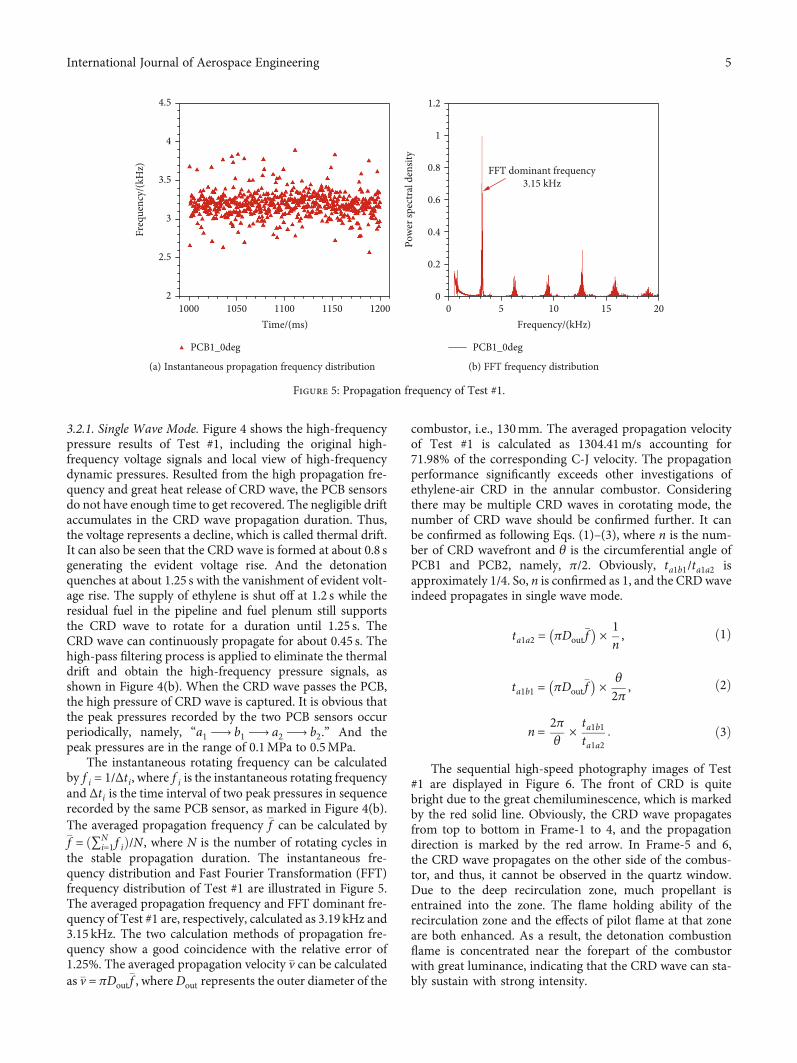
3.2.1. Single Wave Mode. Figure 4 shows the high-frequencypressure results of Test #1, including the original high-frequency voltage signals and local view of high-frequencydynamic pressures. Resulted from the high propagation fre-quency and great heat release of CRD wave, the PCB sensorsdo not have enough time to get recovered. The negligible driftaccumulates in the CRD wave propagation duration. Thus,the voltage represents a decline, which is called thermal drift.It can also be seen that the CRD wave is formed at about 0.8 sgenerating the evident voltage rise. And the detonationquenches at about 1.25 s with the vanishment of evident volt-age rise. The supply of ethylene is shut off at 1.2 s while theresidual fuel in the pipeline and fuel plenum still supportsthe CRD wave to rotate for a duration until 1.25 s. TheCRD wave can continuously propagate for about 0.45 s. Thehigh-pass filtering process is applied to eliminate the thermaldrift and obtain the high-frequency pressure signals, asshown in Figure 4(b). When the CRD wave passes the PCB,the high pressure of CRD wave is captured. It is obvious thatthe peak pressures recorded by the two PCB sensors occurperiodically, namely, “a1 ⟶ b1 ⟶ a2 ⟶ b2.” And thepeak pressures are in the range of 0.1MPa to 0.5MPa.
The instantaneous rotating frequency can be calculatedby f i = 1/Δti, where f i is the instantaneous rotating frequencyand Δti is the time interval of two peak pressures in sequencerecorded by the same PCB sensor, as marked in Figure 4(b).The averaged propagation frequency �f can be calculated by�f = ð∑N
i=1 f iÞ/N , where N is the number of rotating cycles inthe stable propagation duration. The instantaneous fre-quency distribution and Fast Fourier Transformation (FFT)frequency distribution of Test #1 are illustrated in Figure 5.The averaged propagation frequency and FFT dominant fre-quency of Test #1 are, respectively, calculated as 3.19 kHz and3.15 kHz. The two calculation methods of propagation fre-quency show a good coincidence with the relative error of1.25%. The averaged propagation velocity �v can be calculatedas �v = πDout
�f , whereDout represents the outer diameter of the
combustor, i.e., 130mm. The averaged propagation velocityof Test #1 is calculated as 1304.41m/s accounting for71.98% of the corresponding C-J velocity. The propagationperformance significantly exceeds other investigations ofethylene-air CRD in the annular combustor. Consideringthere may be multiple CRD waves in corotating mode, thenumber of CRD wave should be confirmed further. It canbe confirmed as following Eqs. (1)–(3), where n is the num-ber of CRD wavefront and θ is the circumferential angle ofPCB1 and PCB2, namely, π/2. Obviously, ta1b1/ta1a2 isapproximately 1/4. So, n is confirmed as 1, and the CRDwaveindeed propagates in single wave mode.
ta1a2 = πDout�f
� �× 1n, ð1Þ
ta1b1 = πDout�f
� �× θ
2π ,ð2Þ
n = 2πθ
× ta1b1ta1a2
: ð3Þ
The sequential high-speed photography images of Test#1 are displayed in Figure 6. The front of CRD is quitebright due to the great chemiluminescence, which is markedby the red solid line. Obviously, the CRD wave propagatesfrom top to bottom in Frame-1 to 4, and the propagationdirection is marked by the red arrow. In Frame-5 and 6,the CRD wave propagates on the other side of the combus-tor, and thus, it cannot be observed in the quartz window.Due to the deep recirculation zone, much propellant isentrained into the zone. The flame holding ability of therecirculation zone and the effects of pilot flame at that zoneare both enhanced. As a result, the detonation combustionflame is concentrated near the forepart of the combustorwith great luminance, indicating that the CRD wave can sta-bly sustain with strong intensity.
1000 1050 1100 1150Time/(ms)
4.5
4
3.5
3
2.5
2
Freq
uenc
y/(k
Hz)
PCB1_0deg
(a) Instantaneous propagation frequency distribution
0 5 10 15 20Frequency/(kHz)
1.2
0.8
1
0.6
0.4
0.2
0
Pow
er sp
ectr
al d
ensit
y
PCB1_0deg
FFT dominant frequency3.15 kHz
(b) FFT frequency distribution
Figure 5: Propagation frequency of Test #1.
5International Journal of Aerospace Engineering

3.2.2. Counter-Rotating Two-Wave Mode. The local view ofhigh-frequency dynamic pressures of Test #2 is illustratedin Figure 7. It is clear that the pressures fluctuate in“b1 ⟶ a1 ⟶ a2 ⟶ b2” repetition. It indicates that CRDwaves propagate in typical counter-rotating two-wave mode.Inferred from the PCB sensor arrangement and peak pres-sure sequence, a collision is considered to occur betweenthe inferior arc of the circumference segmented by the twoPCB sensors. And the collision location is closer to PCB1,since peak pressure a1 and a2 are between b1 and b2. For bet-ter understanding of the counter-rotating two-wave propaga-tion mode, a schematic view is shown in Figure 8. Thedetonation wave M rotates clockwise while N rotates anti-clockwise. They collide at P1 which is out of the quartz win-dow view. After the collision, the detonation waves evolve
into the transmitted shock waves. Later, the transmittedshock waves are accelerated into the detonation waves M1and N1. Then, N1 passes PCB2 and M1 passes PCB1 insequence generating peak pressures b1 and a1, respectively.After a while, M1 and N1 collide at P2 which is closer toPCB1. Similarly, new detonation wavesM2 andN2 are gener-ated after the collision. N2 passes PCB1 andM2 passes PCB2in sequence generating peak pressures a2 and b2, respectively.Thus, the peak pressures repeat in regular oscillations“b1 ⟶ a1 ⟶ a2 ⟶ b2.” The high-speed photographyimages of counter-rotating two-wave mode in Test #2 areshown in Figure 9. The CRD wave M propagates from topto bottom. Then, it collides with CRD wave N out of thequartz window view. After the collision, transmitted shockwaves evolve into CRD waves again and the waves rotate inthe original direction. Therefore, CRD wave N1 propagatesfrom bottom to top, seen in Frame-7 to 12. Due to the shal-low recirculation zone in the 25mm wide combustor, theflame holding ability of the zone and effects of pilot flameat the zone are both weakened. So that the flame in Test #2is dimmer than that of Test #1, indicating the combustionintensity of counter-rotating two-wave mode is lower thanthat of single wave mode.
Since there are two waves propagating in counter-rotating direction, the propagation period definition is dif-ferent from that of single wave mode. As Figure 7 shows,the time of the complete period is the interval of peakpressures b1-b1 ′ rather than b1-b2. After high-pass filteringprocessing and FFT processing, the instantaneous propa-gation frequency and FFT frequency distribution of Test#2 are shown in Figure 10. Its averaged propagation fre-quency and FFT dominant frequency are, respectively,2.48 kHz and 2.50 kHz, which are in good accordance. More-over, the peak pressures of counter-rotating two-wave modeare much lower than those of single wave mode. This indi-cates that the intensity of counter-rotating two-wave modeis weaker than that of single wave mode. Due to the
Figure 6: High-speed photography images of Test #1.
1.026 1.0265 1.027 1.0275 1.028Time/(s)
0.2
0.3
0.1
0
0.4
Pres
sure
/(M
Pa) Little peak pressures
PCB1_0deg
b1
b1
b1′
b2
Δti–1 Δti+1Δti
PCB2_90deg
a1
a1 a2
a2 b2
Figure 7: Local view of high-frequency dynamic pressures of Test #2.
6 International Journal of Aerospace Engineering

PCB2_90degPCB2_90deg
Quartz window
Detonation waves: M, M1, M2, N, N1, N2
PCB1_0deg PCB1_0degN1
N1
M1
M2
N2
P2
M1
P1
M
N
T T+ΔtQuartz window
Collision: P1, P2
Figure 8: Schematic view of counter-rotating two-waves mode.
Figure 9: High-speed photography images of counter-rotating two-wave mode in Test #2.
7International Journal of Aerospace Engineering

transverse wave effects, there are reflected waves between theinner and outer walls when the annulus width is within a cer-tain range. And this phenomenon was also found and dis-cussed in the investigations of annular combustor [37, 38].
3.2.3. Deflagration. There is no CRD wave propagating cir-cumferentially in the combustor when CRDE works in defla-gration mode. The propellant is consumed by traditionalisobaric combustion. The local view of high-frequencydynamic pressures of Test #3 is illustrated in Figure 11. Thehigh-frequency pressures fluctuate around 0, and there areno obvious peak pressures or periodic oscillations. Theseindicate that there is no pressure wave rotating in the com-bustor. Different from Test #1 and #2, no reliable FFT dom-inant frequency of Test #3 is obtained in the FFT frequencydistribution, as shown in Figure 12. The high-speed photog-raphy images of Test #3 are illustrated in Figure 13. Theimages are quite dim indicating that the intensity of deflagra-tion is much lower than that of CRDmodes. The deflagration
mainly occurs near the forepart of the combustor, and theluminance fades away as the main flow moves downstream.There is no distinct combustion flame rotating circumferen-tially in the combustor, which indicates the CRD wave is notobtained. The axial time-averaged pressures of Test #1-3recorded by P1-P11 are plotted in Figure 14. The time-averaged pressures of Test #1 are the highest while those inTest #3 are the lowest, indicating that the combustion inten-sity of single wave mode, counter-rotating two-wave mode,and deflagration decreases in sequence. P1 is located at thethroat of the air slit while P2 is located close to the entranceof the combustor. Since there is a backward-facing step atthe forepart of the combustor, the cross-sectional area ofthe combustor increases rapidly so that the time-averagedpressure drops remarkably between P1 and P2. With thesame cross-sectional area of the combustor, the pressureincreases moderately reaching the first peak at P4 due tothe combustion. Resulted from the expansion behind the
1000 1050 1100 1150 1200Time/(ms)
5
4.5
4
3.5
3
2.5
2
1
1.5
0.5
Freq
uenc
y/(k
Hz)
PCB1_0deg
(a) Instantaneous propagation frequency distribution
0 5 10 15 20Frequency/(kHz)
1.2
0.8
1
0.6
0.4
0.2
0
Pow
er sp
ectr
al d
ensit
y
PCB1_0deg
FFT dominant frequency2.50 kHz
(b) FFT frequency distribution
Figure 10: Propagation frequency of Test #2.
1.16 1.162 1.164 1.166Time/(s)
1.168 1.17−0.8
−0.4
0
0.4
Pres
sure
/(M
Pa) [
PCB1
]
−0.4
−0.2
0
0.4
0.6
0.8
0.2
Pres
sure
/(M
Pa) [
PCB2
]
PCB1_0degPCB2_90deg
Figure 11: Local view of high-frequency dynamic pressures of Test #3.
0 5 10 15 20Frequency/(kHz)
0.8
1
0.6
0.4
0.2
0
Pow
er sp
ectr
al d
ensit
y
PCB1_0deg
Figure 12: FFT frequency distribution of Test #3.
8 International Journal of Aerospace Engineering

CRD wave, the time-averaged pressure declines between P4and P8. Affected by the outlet pressure at the exit of the com-bustor, a second peak of time-averaged pressure occurs at P9.
3.3. Effects of Combustor Width. The effects of combustorwidth on CRD are summarized in this section. As analyzedabove, the highest time-averaged pressure is located withinthe CRD wave front at the combustor forepart. Thus, thetime-averaged pressure of P4 is used to represent the com-bustor pressure and to estimate the effects of combustorwidth on the combustion, as shown in Figure 15. In general,the pressure of P4 increases as the combustor width enlarges,mainly due to the difference in combustion mode. The min-imal pressure is produced in deflagration mode in combustorW-20. Higher pressure is obtained in counter-rotating two-
wave mode while the highest pressure is achieved in singlewave mode. These indicate the CRD mode can obtain higherpressure gain than that of conventional isobaric combustion.The pressure obtained in combustor W-35 is quite close tothat in combustorW-40 when ER is lower than 1.2. However,the pressure in combustor W-40 drops dramatically while itkeeps stable in combustor W-35 on highly rich ER. It canbe inferred that optimal propulsive performance may beachieved in combustor W-35. In addition, P4 pressure ineach combustor first increases and then drops as ER increasesfrom lean stage to rich stage. Since high chemical activity ofpropellant is achieved when the propellant is stoichiometric,high pressures are obtained in that condition.
The effects of combustor width on propagation frequencyare shown in Figure 16, and the discussion is only on thedetonation modes. The propagation frequency is positivelycorrelated with the combustor width. In combustors W-40,W-35, andW-30, the CRD waves all propagate in single wavemode and the frequency obtained in these combustors isslightly affected by ER variation. In this paper, the highestfrequency and velocity of the CRD wave propagation are cor-respondingly 3.24 kHz and 1325.56m/s on the ER of 1.12obtained in combustor W-40. The highest velocity accountsfor 71.51% of the corresponding C-J velocity, and it exceedsother investigations [24–27]. With the decrease of combustorwidth, the counter-rotating two-wave mode is observed incombustors W-25 and W-20. In the 20mm wide combustor,the frequency is quite low in the range of 2.21-2.32 kHz andthe averaged velocity only accounts for 50.31%-52.41% ofthe corresponding C-J velocity. A great velocity deficit occursin the 20mm wide combustor. As mentioned in Section 3.1,when the width decreases, the effects of pilot flame get weak-ened and the mixing quality gets poor as the backward-facingstep shallows. Both the weakened effects of pilot flame andpoor mixing quality may lead to the decrease of combustionintensity and propagation velocity. In addition, the collisionof waves also contributes to the great velocity deficit.
Figure 13: High-speed photography images of Test #3.
0 50
P4
P1
P9Throat
100
First peak
Second peak
150 200Axial distance/(mm)
250
300
200
150
100
50
Pres
sure
/(kP
a)
Test #1Test #2Test #3
Figure 14: Pressure-distance distribution of Test #1-3.
9International Journal of Aerospace Engineering

The effects of combustor width on propagation stabil-ity are illustrated in Figure 17. The relative standard devi-ation of the instantaneous propagation frequency in thepropagation duration is used to quantitatively evaluate
the stability. The calculation methods are defined as S =ffiffiffiffiffiffiffiffiffiffiffiffiffiffiffiffiffiffiffiffiffiffiffiffiffiffiffiffiffiffiffiffiffi∑N
1 f i − �f /ðN − 1Þq
and μ = S/f , where S is standard devi-
ation, N is the number of propagation cycles, and μ is rel-ative standard deviation [29]. The propagation stability isnegatively correlated with the combustor width in differentCRD propagation modes. Severe instability happens incounter-rotating two-wave mode, and the deviation can beas high as 33.67% in combustor W-20. On the contrary, quitestable CRD wave propagation is obtained in single wave and
the deviations are all below 15% in combustor W-40. It canbe inferred that large combustor width contributes to stablepropagation of CRD wave. Besides, the deviation goes downfirst and then rises as ER increases. The minimal value isobtained when ER is about 1.0 in each combustor. WhenER is about 1.0, the chemical activity of the propellant is highso that the propellant is easier to get ignited. This is beneficialfor stable propagation of the CRD wave. In conclusion, widecombustor and stoichiometric ER both contribute to the sta-ble propagation of the CRD wave.
4. Conclusions
To figure out the effects of combustor width on the ethylene-air CRD in the annular combustor, a series of tests are con-ducted with ER variation in combustors with differentwidths. Through the pressure measure results and high-speed photograph images, experiment results have beenanalyzed in detail. The conclusions are drawn as follows:
(1) The combustor width has great effects on the realiza-tion of ethylene-air CRD, and the critical combustorwidth for ethylene-air CRD realization is 20mm inthis paper. There is a deep backward-facing step atthe combustor forepart when the combustor widthis large. Thus, the main flow slows down due to therapid increase of the combustor cross-sectional area,and the mixing quality is promoted. Besides, the pilotflame at the recirculation zone can greatly conduce tothe realization and stable propagation of CRD wave
(2) The combustor width also has effects on the CRDwave propagation modes, and the critical combustorwidth to obtain single wave is 25mm in this paper. Asthe width increases, the propagation mode changesfrom counter-rotating two-wave mode to single wavemode. The characteristics of both modes are well
0.8 1 1.2 1.4Equivalence ratio
160
180
200
140
120
100
80
Pres
sure
/(kP
a)
W-20W-25
W-35
Test #1
W-40
Test #2
Counter-rotatingtwo-waveDeflagration
W-30
Test #3
Figure 15: Effects of combustor width on P4 pressure in thecombustor.
0.8 1 1.2 1.4Equivalence ratio
3.5
3
2.5
2
Freq
uenc
y/(k
Hz)
W-35W-40
Counter-rotatingtwo-wave
W-20W-25W-30
Figure 16: Effects of combustor width on propagation frequency.
0.8 1 1.2 1.4Equivalence ratio
20
30
25
35
40
15
10
5
0
Rela
tive s
tand
ard
devi
atio
n/(%
)
W-20W-25
W-35W-40
Counter-rotating two-
wave
W-30
Figure 17: Effects of combustor width on propagation stability.
10 International Journal of Aerospace Engineering

analyzed by high-frequency pressure and high-speedphotograph images
(3) Single wave mode is achieved in wide operating rangein wide combustors, and the CRD wave propagateswith high frequency in this mode. On the ER of1.12 in combustor W-40, the highest averaged prop-agation frequency and velocity are 3.24 kHz and1325.56m/s, respectively. The velocity accounts for71.51% of the corresponding C-J velocity
(4) When the combustor width is large, high combustorpressure and stable CRD propagation are bothobtained. In spite of large combustor volume, higherpressure is acquired by the detonation combustion inwide combustors compared with that of deflagrationin combustor W-20. The relative standard deviationof the instantaneous propagation frequency decreasesdramatically as the combustor width increases. Thedeviation can be lower than 15% in single wave modein combustor W-40. It can be inferred that a betterpropulsive performance could be approached by thedetonation combustion, especially for single wavemode
This paper will provide a deeper understanding of hydro-carbon CRD realization mechanism and enrich the combus-tor design theory for CRDE.
Data Availability
The data used to support the findings of this study areavailable from the corresponding author upon request.
Conflicts of Interest
The authors declare there is no conflict of interest regardingthe publication of this paper.
Acknowledgments
This work is supported by the National Natural ScienceFoundation of China through Grant No. (51776220 and91541103).
References
[1] F. A. Bykovskii and E. F. Vedernikov, “Self-sustaining pulsat-ing detonation of gas-mixture flow,” Combustion, Explosion,and Shock Waves, vol. 32, no. 4, pp. 442–448, 1996.
[2] D. S. Stewart and A. R. Kasimov, “State of detonation stabilitytheory and its application to propulsion,” Journal of Propulsionand Power, vol. 22, no. 6, pp. 1230–1244, 2006.
[3] V. F. Nikitin, V. R. Dushin, Y. G. Phylippov, and J. C. Legros,“Pulse detonation engines: technical approaches,” Acta Astro-nautica, vol. 64, no. 2-3, pp. 281–287, 2009.
[4] X. Cai, J. Liang, R. Deiterding, Y. Che, and Z. Lin, “Adaptivemesh refinement based simulations of three-dimensional det-onation combustion in supersonic combustible mixtures witha detailed reaction model,” International Journal of HydrogenEnergy, vol. 41, no. 4, pp. 3222–3239, 2016.
[5] W. Lin, J. Zhou, S. Liu, Z. Lin, and F. Zhuang, “Experimentalstudy on propagation mode of H2/air continuously rotatingdetonation wave,” International Journal of Hydrogen Energy,vol. 40, no. 4, pp. 1980–1993, 2015.
[6] V. Anand, A. St. George, R. Driscoll, and E. Gutmark, “Inves-tigation of rotating detonation combustor operation with H2-air mixtures,” International Journal of Hydrogen Energy,vol. 41, no. 2, pp. 1281–1292, 2016.
[7] S. A. Zhdan, “Mathematical model of continuous detonationin an annular combustor with a supersonic flow velocity,”Combustion, Explosion, and Shock Waves, vol. 44, no. 6,pp. 690–697, 2008.
[8] M. Hishida, T. Fujiwara, and P. Wolanski, “Fundamentals ofrotating detonations,” Shock Waves, vol. 19, no. 1, pp. 1–10,2009.
[9] T. Gaillard, D. Davidenko, and F. Dupoirieux, “Numericalsimulation of a rotating detonation with a realistic injectordesigned for separate supply of gaseous hydrogen and oxy-gen,” Acta Astronautica, vol. 141, pp. 64–78, 2017.
[10] C. A. Nordeen, D. Schwer, F. Schauer, J. Hoke, T. Barber, andB. M. Cetegen, “Role of inlet reactant mixedness on the ther-modynamic performance of a rotating detonation engine,”Shock Waves, vol. 26, no. 4, pp. 417–428, 2016.
[11] J. Sun, J. Zhou, S. Liu, Z. Lin, and J. Cai, “Effects of injectionnozzle exit width on rotating detonation engine,” Acta Astro-nautica, vol. 140, pp. 388–401, 2017.
[12] J. Sun, J. Zhou, S. Liu, Z. Lin, andW. Lin, “Plume flowfield andpropulsive performance analysis of a rotating detonationengine,” Aerospace Science and Technology, vol. 81, pp. 383–393, 2018.
[13] J. Sun, J. Zhou, S. Liu, and Z. Lin, “Numerical investigation of arotating detonation engine under premixed/non-premixedconditions,” Acta Astronautica, vol. 152, pp. 630–638, 2018.
[14] B. V. Voitsekhovskii, “Stationary detonation,” Doklady Akade-mii Nayk USSR, vol. 129, pp. 1254–1256, 1959.
[15] J. A. Nicholls, R. E. Cullen, and K. W. Ragland, “Feasibilitystudies of a rotating detonation wave rocket motor,” Journalof Spacecraft and Rockets, vol. 3, no. 6, pp. 893–898, 1966.
[16] E. Braun, N. Dunn, and F. Lu, “Testing of a continuous deto-nation wave engine with swirled injection,” in 48th AIAAAerospace Sciences Meeting Including the New Horizons Forumand Aerospace Exposition, Orlando, FL, USA, January 2010.
[17] L. Peng, D. Wang, X. Wu, H. Ma, and C. Yang, “Ignitionexperiment with automotive spark on rotating detonationengine,” International Journal of Hydrogen Energy, vol. 40,no. 26, pp. 8465–8474, 2015.
[18] C. Yang, X. Wu, H. Ma, L. Peng, and J. Gao, “Experimentalresearch on initiation characteristics of a rotating detonationengine,” Experimental Thermal and Fluid Science, vol. 71,pp. 154–163, 2016.
[19] S. Liu, W. Liu, Z. Lin, and W. Lin, “Experimental research onthe propagation characteristics of continuous rotating detona-tion wave near the operating boundary,” Combustion Scienceand Technology, vol. 187, no. 11, pp. 1790–1804, 2015.
[20] X. M. Tang, J. P. Wang, and Y. T. Shao, “Three-dimensionalnumerical investigations of the rotating detonation enginewith a hollow combustor,” Combustion and Flame, vol. 162,no. 4, pp. 997–1008, 2015.
[21] F. A. Bykovskii, S. A. Zhdan, and E. F. Vedernikov, “Continu-ous spin detonation of fuel-air mixtures,” Combustion, Explo-sion and Shock Waves, vol. 42, no. 4, pp. 463–471, 2006.
11International Journal of Aerospace Engineering

[22] J. Kindracki, “Experimental research on rotating detonation inliquid fuel-gaseous air mixtures,” Aerospace Science and Tech-nology, vol. 43, pp. 445–453, 2015.
[23] B. Le Naour, F. H. Falempin, and K. Coulon, “MBDA R&Teffort regarding continuous detonation wave engine forpropulsion-status in 2016,” in 21st AIAA International SpacePlanes and Hypersonics Technologies Conference, Xiamen,China, March 2017.
[24] K. Y. Cho, J. R. Codoni, B. A. Rankin, J. Hoke, and F. Schauer,“High-repetition-rate chemiluminescence imaging of a rotat-ing detonation engine,” in 54th AIAA Aerospace Sciences Meet-ing, San Diego, CA, USA, January 2016.
[25] A. C. St. George, R. B. Driscoll, V. Anand, D. E. Munday,and E. J. Gutmark, “Fuel blending as a means to achieveinitiation in a rotating detonation engine,” in 53rd AIAAAerospace Sciences Meeting, Kissimmee, FL, USA, January2015.
[26] I. Q. Andrus, M. D. Polanka, P. I. King, F. R. Schauer, and J. L.Hoke, “Experimentation of premixed rotating detonationengine using variable slot feed plenum,” Journal of Propulsionand Power, vol. 33, no. 6, pp. 1448–1458, 2017.
[27] J. Wilhite, R. B. Driscoll, A. C. St. George, V. Anand, and E. J.Gutmark, “Investigation of a rotating detonation engine usingethylene-air mixtures,” in 54th AIAA Aerospace Sciences Meet-ing, San Diego, CA, USA, January 2016.
[28] H. Peng, W. Liu, and S. Liu, “Ethylene Continuous RotatingDetonation in optically accessible racetrack-like combustor,”Combustion Science and Technology, vol. 191, no. 4-6,pp. 676–695, 2019.
[29] H. Peng, W. Liu, S. Liu, and H. Zhang, “Experimental investi-gations on ethylene-air continuous rotating detonation wavein the hollow chamber with Laval nozzle,” Acta Astronautica,vol. 151, pp. 137–145, 2018.
[30] V. Anand, A. St. George, C. Farbos de Luzan, andE. Gutmark, “Rotating detonation wave mechanics throughethylene-air mixtures in hollow combustors, and implica-tions to high frequency combustion instabilities,” Experi-mental Thermal and Fluid Science, vol. 92, pp. 314–325,2018.
[31] Y.Wang, J. le, C.Wang, and Y. Zheng, “A non-premixed rotat-ing detonation engine using ethylene and air,” Applied Ther-mal Engineering, vol. 137, pp. 749–757, 2018.
[32] A. Kawasaki, T. Inakawa, J. Kasahara et al., “Critical conditionof inner cylinder radius for sustaining rotating detonationwaves in rotating detonation engine thruster,” Proceedingsof the Combustion Institute, vol. 37, no. 3, pp. 3461–3469,2019.
[33] H. Peng, W. D. Liu, S. Liu, and H. L. Zhang, “The effect ofcavity on ethylene-air continuous rotating detonation in theannular combustor,” International Journal of HydrogenEnergy, vol. 44, no. 26, pp. 14032–14043, 2019.
[34] S.-J. Liu, H. Y. Peng, W. D. Liu, and H. L. Zhang, “Effects ofcavity depth on the ethylene-air continuous rotating detona-tion,” Acta Astronautica, vol. 166, pp. 1–10, 2020.
[35] H. Y. Peng, W. D. Liu, S. J. Liu, and H. L. Zhang, “Effects ofcavity location on ethylene–air continuous rotating detonationin a cavity-based annular combustor,” Combustion Science andTechnology, vol. 192, pp. 1–22, 2020.
[36] F. A. Bykovskii, S. A. Zhdan, and E. F. Vedernikov, “Continu-ous spin detonations,” Journal of Propulsion and Power,vol. 22, no. 6, pp. 1204–1216, 2006.
[37] R. Zhou and J.-P. Wang, “Numerical investigation of shockwave reflections near the head ends of rotating detonationengines,” Shock Waves, vol. 23, no. 5, pp. 461–472, 2013.
[38] H. Zhang, W. Liu, and S. Liu, “Effects of inner cylinder lengthon H2/air rotating detonation,” International Journal ofHydrogen Energy, vol. 41, no. 30, pp. 13281–13293, 2016.
12 International Journal of Aerospace Engineering