effect of high frequency cable attenuation on lightning … · overvoltages in distribution...
TRANSCRIPT
Abstract: The high frequency attenuation of XLPE and EPRcables differ substantially. The absorption of high frequencyenergy between the cable termination at an overhead line andcable-connected transformers can reduce substantially light-ning-induced turn-to-turn overvoltages at the top of the trans-former primary winding. This is especially true when the leadlengths of the arrester across the cable termination are longerthan desirable, resulting in greatly increased lightning inducedvoltages across the cable termination. The computed data pre-sented in this paper indicate that the arrester lead length, light-ning rising time, the type of cable, and the length of cable havesubstantial impact on the overvoltage to which a transformer issubjected and the voltage across the top few turns of the trans-former winding. The greater high frequency losses of EPR cablecan increase substantially the risetime of lightning induced over-voltages. This results in much lower overvoltages in the first fewturns of distribution transformers connected to the undergroundcable.
Key Words: Distribution cable, power cable, surge overvoltages
I. INTRODUCTION Fast transients in power systems can be generated by lightningimpulses and switching of devices such as vacuum, air or SF6insulated interrupters [1]. In the case of lightning-inducedovervoltages in distribution systems, the ultimate overvoltagein the absence of an arrester would be the same as in a trans-mission system, meaning very large relative to the BIL of thedistribution system. Lightning current risetimes range from0.1 µs to many µs. Gapless ZnO arresters limit the voltageearly into the rise, which means at very short times. Thus a 40kA lightning current waveform with a risetime of 0.2 µs canresult in a voltage waveform across the arrester with a risetimeof only 20 ns. In addition, the effect of arrester leads, typicallywith a total length (sum of high voltage and ground connec-tion conductors) in the range of 1 to 3 m (3 to 10 ft) long, canincrease the initial voltage across the cable termination byseveral times, from the range of 40 kV with no leads to 250kV with 3 m (10 ft) total lead length (Figure 1). As a result ofthese phenomena, a distribution cable connected to an over-head distribution circuit may see transient waveforms in therange of 25 pu (relative to peak AC line-to-ground voltage)with risetimes in the range of 100 ns. In the absence of highfrequency cable attenuation, these short risetime, large ampli-tude transients can cause a large voltage across the first fewturns of a transformer winding, leading to turn-to-turn failure.
As seen in Figures 2-4, high frequency cable attenuation canreduce the amplitude, but more importantly, the rate of rise(dV/dt) of lightning and switching induced transients as afunction of distance propagated down the cable, extending thetransient risetime by absorbing high frequency energy,thereby reducing the turn-to-turn voltage at the top of thetransformer windings connected along the cable. EPR cable,which has much greater high frequency attenuation thanXLPE, is more effective in protecting cable-connected trans-formers from the effects of lighting surges. In the presentwork, we have modeled the distribution circuits shown inFigure 5 which were provided by a local utility, and we havecomputed the voltage across transformers and the transientvoltage across the top 10% of the transformer windings. Theeffects of ZnO arrester lead length, lightning current risingtime, the type of cable (TR-XLPE or EPR cable) and thelength of cable were evaluated using the ATP-EMTP program.The distribution transformers were modeled as shown in Fig-ure 6.
II. CABLE ATTENUATION The attenuation of shielded power cable is caused by threephenomena, (i) skin effect loss of the conductors, (ii) dielec-tric loss of the insulation, and (iii) dielectric loss in the semi-cons. As a result of the large conductors employed in powercables, skin effect losses are normally negligible. For cablesinsulated with XLPE, which has very low dielectric loss, lowfrequency losses are dominated by conductor resistance anddielectric loss while high frequency losses are dominated by
Effect of High Frequency Cable Attenuation on Lightning-Induced Overvoltages at Transformers
Li-Ming Zhou, Senior Member, IEEE and Steven Boggs, Fellow, IEEE
Time (µs)0 1 2 3 4 5 6 7 8 9 10
Vol
tage
(kV
)-100
-50
0
50
100
150
200
250
3 m arrester lead0 m arrester lead
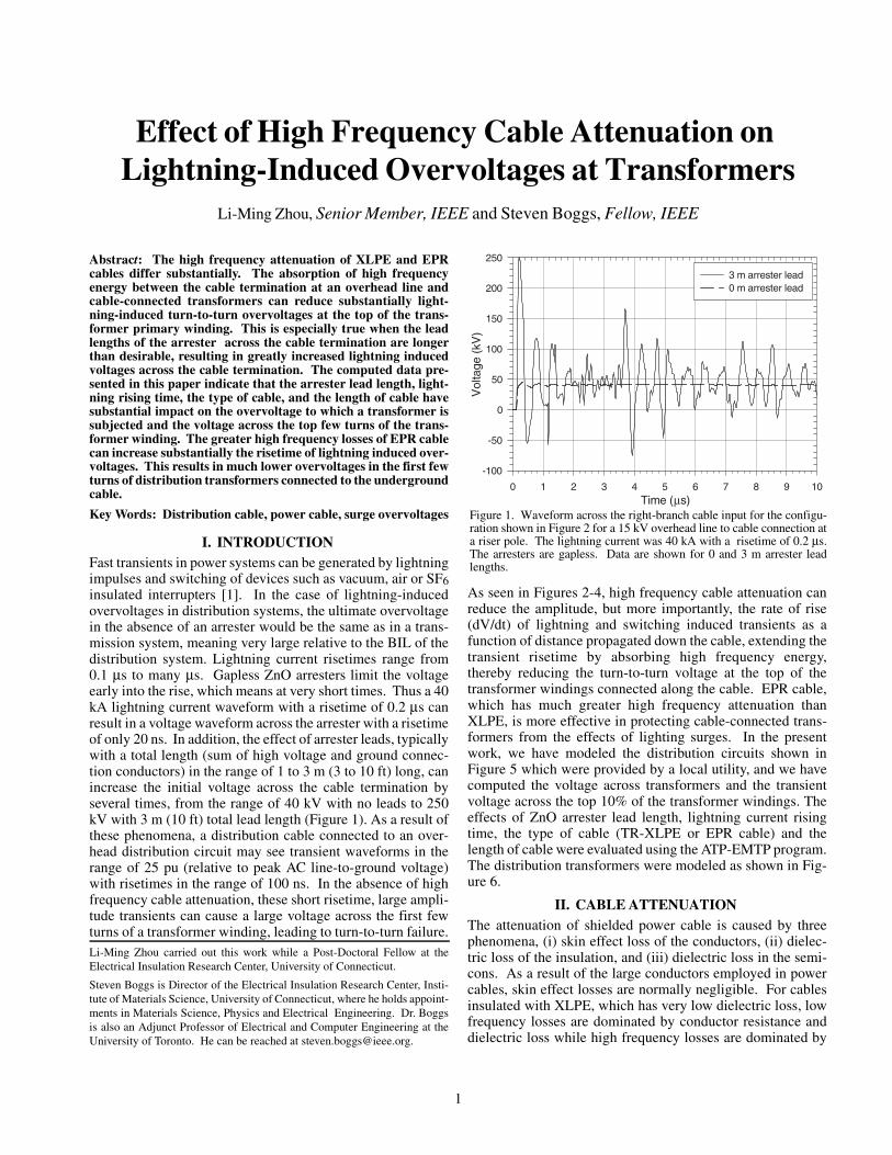
Figure 1. Waveform across the right-branch cable input for the configu-ration shown in Figure 2 for a 15 kV overhead line to cable connection ata riser pole. The lightning current was 40 kA with a risetime of 0.2 µs.The arresters are gapless. Data are shown for 0 and 3 m arrester leadlengths.
Li-Ming Zhou carried out this work while a Post-Doctoral Fellow at theElectrical Insulation Research Center, University of Connecticut.
Steven Boggs is Director of the Electrical Insulation Research Center, Insti-tute of Materials Science, University of Connecticut, where he holds appoint-ments in Materials Science, Physics and Electrical Engineering. Dr. Boggsis also an Adjunct Professor of Electrical and Computer Engineering at theUniversity of Toronto. He can be reached at [email protected].
1
dielectric loss in the semicons which results from the propa-gation of radial displacement current through the resistance ofthe semicon [3,4]. This loss is maximum when the resistiveimpedance of the semicon is equal to its capacitive impedance.Since the resistive impedance is relatively constant with fre-quency while the capacitive impedance decreases with in-creasing frequency, the two tend to be equal only in a smallrange of frequency, usually in the MHz range. The magnitudeof the attenuation is a strong function of the semicon dielectricconstant, and the relative dielectric constant is usually in the
range of 100 to 2000. Such high dielectric constants result inlow attenuations and small contributions to the dielectric loss,as seen in Figure 7.
Figure 8 shows the measured attenuations vs. frequency forEPR cable and TR-XLPE cable. The TR-XLPE cable has ahigh frequency attenuation which is in the range caused bysemicons. However, the EPR cable has an order of magnitudegreater attenuation at high frequencies, in a range which isprobably caused by dielectric loss in the insulation.
100 m 300 m 500 m0 m
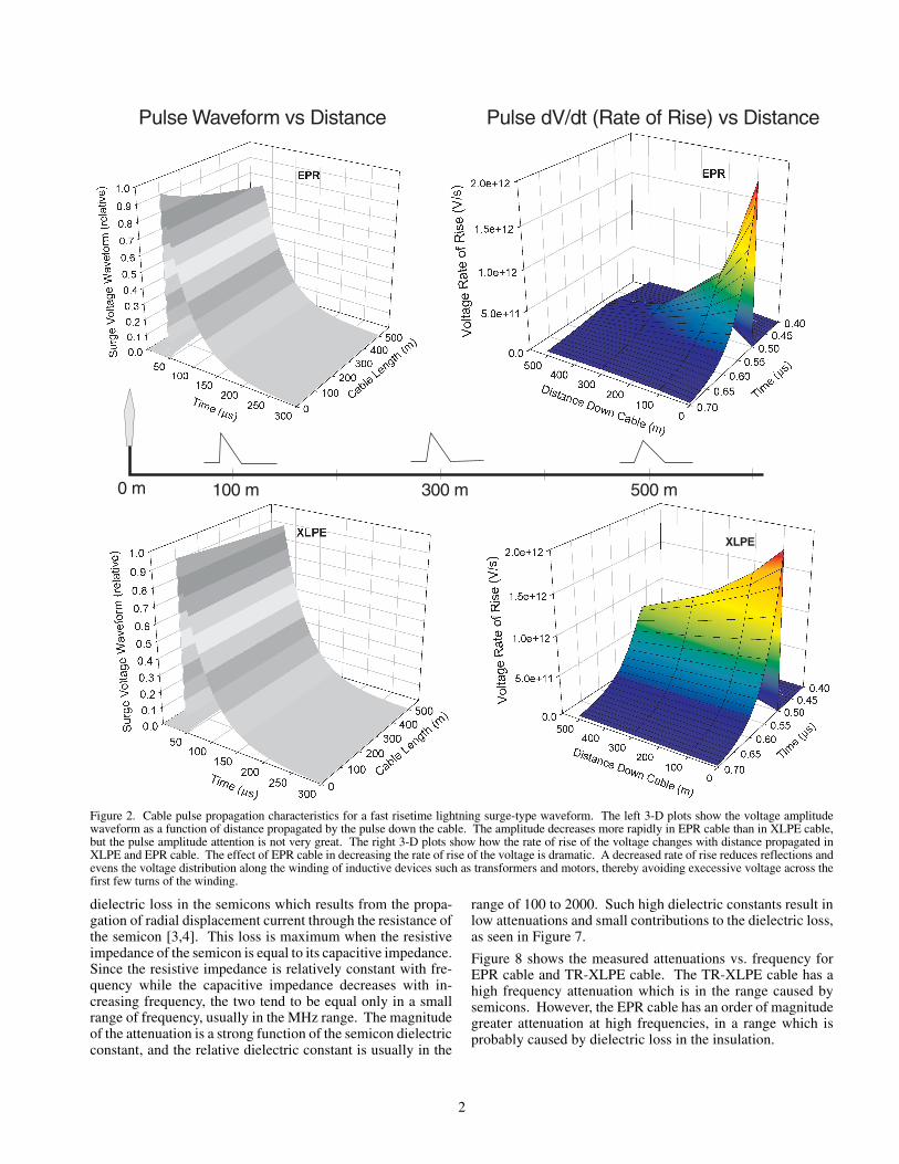
Pulse Waveform vs Distance Pulse dV/dt (Rate of Rise) vs Distance
XLPE
Figure 2. Cable pulse propagation characteristics for a fast risetime lightning surge-type waveform. The left 3-D plots show the voltage amplitudewaveform as a function of distance propagated by the pulse down the cable. The amplitude decreases more rapidly in EPR cable than in XLPE cable,but the pulse amplitude attention is not very great. The right 3-D plots show how the rate of rise of the voltage changes with distance propagated inXLPE and EPR cable. The effect of EPR cable in decreasing the rate of rise of the voltage is dramatic. A decreased rate of rise reduces reflections andevens the voltage distribution along the winding of inductive devices such as transformers and motors, thereby avoiding execessive voltage across thefirst few turns of the winding.
2

III. DISTRIBUTION NETWORK MODELA section of distribution network provided by a utility isshown in Figure 5, which consists of single-phase 13.2 kVdistribution lines, two riser poles, two ZnO arresters at theriser poles, shielded power cables and seven distribution trans-formers. The cables are connected at riser poles, which arefitted with ground leads connected to driven ground rods. Ourprevious work indicated that the ground rod to earth resistancein the New England area ranges from a few ohms to a few kΩ.In the present model, we have employed the somewhat opti-
mistic value of 50 Ω. The distribution overhead lines aremodeled with 150 Ω characteristic impedance, and the riserpole ground leads are modeled as having a 75 Ω characteristicimpedance as implemented in the ATP-EMTP using the con-stant-parameter line model. ZnO arresters were modeled asexponential current-dependent resistor with typical current-voltage characteristics of a distribution-class metal oxide ar-rester. A high frequency model of a single-phase distributiontransformer provided in the literature [2] was used in the pre-sent model without consideration of transformer core loss(Figure 6).
A Marti frequency-dependent single-core cable model wasconstructed in the ATP-EMTP which resulted in the sameelectromagnetic propagation characteristics as the actual ca-ble. The Marti model is based on skin effect losses, which goas the square root of frequency. In the frequency range of
Figure 3 shows how the waveform risetime changes as a function of dis-tance propagated down the EPR and XLPE cable, along with the effectthis has on the voltage across the top 10% of a typical distribution trans-former. Take, for example, a propagation distance of 300 m (about 1000ft). We can see that the risetime at that distance for an XLPE cable wouldbe about 0.15 µs. Following that risetime up to the curve for voltageacross the top 10% of the winding, we can see that this risetime would re-sult in about 43% of the peak surge voltage dropping across the top 10%of the winding. However, for EPR cable, the risetime would be about 0.65µs, and the voltage across the top 10% of the winding would be only 26%of the peak surge voltage, which reduces greatly the surge-induced stresson the winding.
Figure 4 shows the relationship between the percent of the overvoltageacross the top 10% of the transformer winding as a function of the dis-tance propagated by a 0.1 µs risetime lightning impulse down EPR andTR-XLPE cables. The greater high frequency attenuation of the EPR ca-ble causes the percent of the voltage across the top 10% of the winding todrop much more rapidly than for TR-XLPE cable, thereby protecting thetransformer from failure at the top of the winding.
Figure 6. High frequency electrical model for single-phase distributiontransformer [2].
Figure 5. Section of utility 13.2 kV distribution system which has beenmodeled. The transformers are modeled as shown in Figure 3. The cablelengths are labeled in metres.
3
interest, the measured losses could be fit well with a squareroot of frequency dependence. The conductor conductivitywas adjusted in the model so that the computed loss was closeto the measured loss, resulting in the parameters shown inTable 1. As shown in Figure 8, good agreement was obtainedbetween the measured and modeled high frequency cable at-tenuations in the relevant frequency range to about 20 MHz,which corresponds to a wavefront risetime of about 15 ns. Forcomparison, a reference cable model with about one order ofmagnitude less attenuation than TR-XLPE (or two orders ofmagnitude less attenuation than EPR cable) was also em-ployed as “lossless” cable. The measured cable charac-teristics and model parameters which matched measuredlosses are given in Table 1.
IV. LIGHTNING INDUCED OVERVOLTAGES A. Effect of Arrester Lead
Lightning strikes are normally modeled as current surges.The peak in the probability density distribution for lightningcurrent is in the range of 40 kA. The current risetime can varyfrom about 0.1 to several µs. This current is injected into the
10-4
10-3
10-2
10-510-410-310-210-1100
10
100
1000
Cab
le T
an(
)
Conductor Semicon Conductivity (S/m)C
ondu
ctor
Sem
icon
Die
lect
ric C
onst
antδ
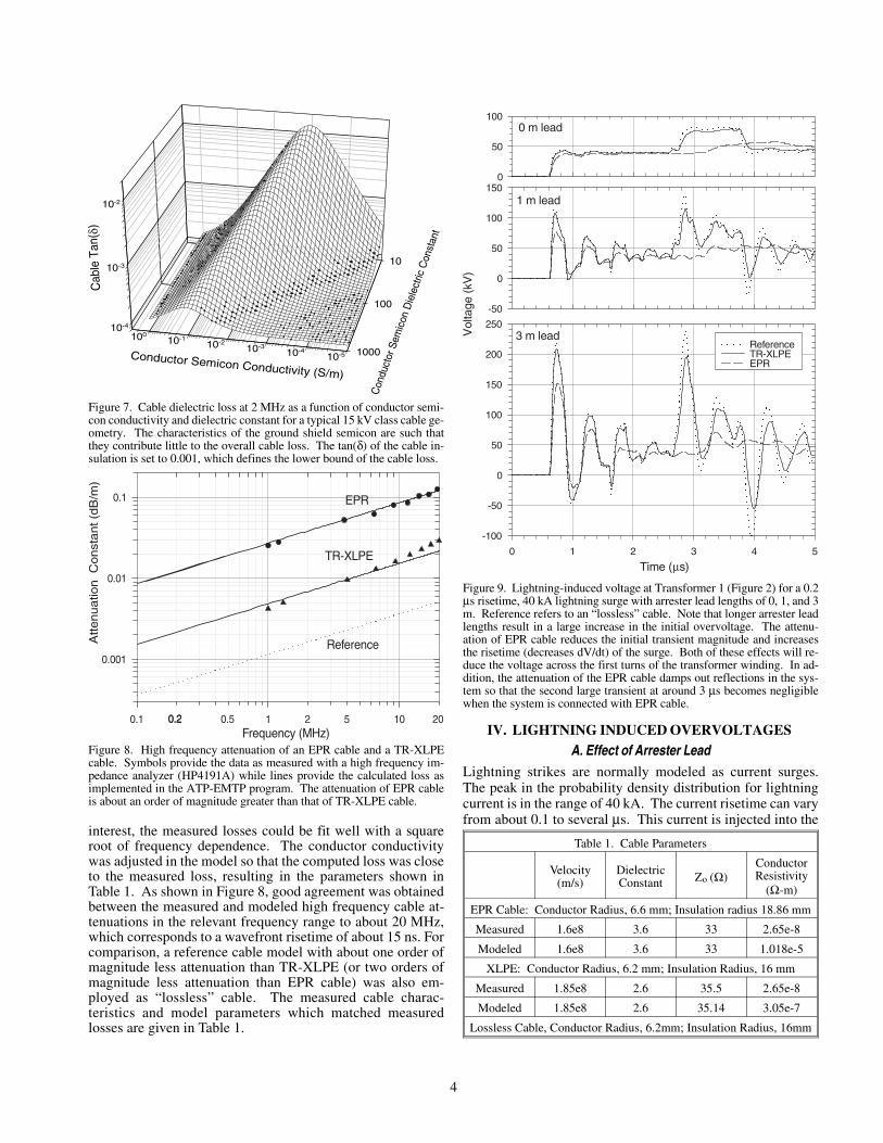
Figure 7. Cable dielectric loss at 2 MHz as a function of conductor semi-con conductivity and dielectric constant for a typical 15 kV class cable ge-ometry. The characteristics of the ground shield semicon are such thatthey contribute little to the overall cable loss. The tan(δ) of the cable in-sulation is set to 0.001, which defines the lower bound of the cable loss.
Figure 8. High frequency attenuation of an EPR cable and a TR-XLPEcable. Symbols provide the data as measured with a high frequency im-pedance analyzer (HP4191A) while lines provide the calculated loss asimplemented in the ATP-EMTP program. The attenuation of EPR cableis about an order of magnitude greater than that of TR-XLPE cable.
Frequency (MHz)0.1 1 10
Attenuatio
nC
onst
ant(d
B/m
)
0.001
0.01
0.1 EPR
TR-XLPE
Reference
0.20.2 20.5 5 20
Vol
tage
(kV
)
-50
0
50
100
150
Time (µs)0 1 2 3 4 5
-100
-50
0
50
100
150
200
250
0
50
100
ReferenceTR-XLPEEPR
0 m lead
1 m lead
3 m lead
Figure 9. Lightning-induced voltage at Transformer 1 (Figure 2) for a 0.2µs risetime, 40 kA lightning surge with arrester lead lengths of 0, 1, and 3m. Reference refers to an “lossless” cable. Note that longer arrester leadlengths result in a large increase in the initial overvoltage. The attenu-ation of EPR cable reduces the initial transient magnitude and increasesthe risetime (decreases dV/dt) of the surge. Both of these effects will re-duce the voltage across the first turns of the transformer winding. In ad-dition, the attenuation of the EPR cable damps out reflections in the sys-tem so that the second large transient at around 3 µs becomes negligiblewhen the system is connected with EPR cable.
Table 1. Cable Parameters
Velocity(m/s)
DielectricConstant Zo (Ω)
ConductorResistivity
(Ω-m)
EPR Cable: Conductor Radius, 6.6 mm; Insulation radius 18.86 mm
Measured 1.6e8 3.6 33 2.65e-8
Modeled 1.6e8 3.6 33 1.018e-5
XLPE: Conductor Radius, 6.2 mm; Insulation Radius, 16 mm
Measured 1.85e8 2.6 35.5 2.65e-8
Modeled 1.85e8 2.6 35.14 3.05e-7
Lossless Cable, Conductor Radius, 6.2mm; Insulation Radius, 16mm
4

impedance of the distribution network at the point of thestrike. We assume that the lightning strikes near mid-span, asshown in Figure 5. The initial impedance seen by the light-ning-induced current will be a 75 Ω, as the transient propa-gates down the overhead line in both directions away from thestrike position. The transmitted surges propagate along theoverhead line until they reach the ZnO arresters, where achange in surge impedance causes reflections and refractions.When a typical 40 kA, 0.2 µs lightning surge is injected, thelightning overvoltage waveform at the right cable terminationof Figure 5 is as shown in Figure 1. The magnitude of thetransient voltage which propagates down the cable to thetransformers is mainly determined by arrester discharge volt-age, the lead lengths on the arresters, and the rate-of-rise ofsurge current. This voltage is approximately the sum of ar-rester voltage and the arrester lead-induced voltage, which isa function of the lead length and rate-of-rise of current surge(dI/dt). In the ideal case of no leads, the voltage propagatingdown to the cable is around 40 kV.
However, a total arrester lead length up to 3 m is often encoun-tered in practice. These leads produce an overvoltage due tothe rate-of-rise of current propagating down the leads. Figure9 shows the voltage waveform across Transformer 1 (Figure5) for arrester lead lengths of 0, 1, and 3 m. In each case, threewaveforms are shown, one for a “lossless” cable, one for aTR-XLPE cable and one for an EPR cable. With increasingarrester lead length, the overvoltages across the transformerincreases significantly. For instance, the voltage peaks ofabout 200 kV are produced across Transformer 1 for an ar-
rester lead length of 3 m, which is about twice of the typicalBIL (95 kV) of 15 kV class switchgear. However high-fre-quency attenuation in the cable can reduce this overvoltagesubstantially. As is clear from Figure 9, the greater high fre-quency attenuations of the EPR cable both reduces the ampli-tude of the initial overvoltage (the first peak in Figure 9) andalso increases the surge risetime. The EPR cable also dampsthe waveform very rapidly, so that by the time of the secondlarge voltage peak for the lossless and TR-XLPE cables(around 3 µs in Figure 9), the voltage amplitude for the EPRcable is negligible. Thus the EPR cable both decreases theimpact of the first voltage peak and nearly eliminates sub-sequent voltage peaks.
B. Effect of Surge Rate-of-RiseThe rate-of-rise of lightning current has significant influenceon the level of overvoltages produced at the cable termination.We investigated this influence with a 40 kA lightning currentwaveform with risetimes varying from 0.1 to 1 µs. The volt-age across the transformers was calculated in the case of 1-marrester lead lengths. Figure 10 shows the voltages acrossTransformer 1 (Figure 5) for 0.1, 0.5 and 1 µs lightning cur-rent risetime and indicates that shorter current risetimes causegreater peak voltages and larger dV/dt across the transformer.Again, EPR cable reduces the initial peak magnitude, de-creases the maximum dV/dt to which the transformer is ex-posed, and damps the surge waveform to minimize the effectof subsequent voltage peaks caused by reflections.
C. Effect of Cable LengthThe voltage across Transformer 1 was calculated as a functionof cable length between the riser pole and Transformer 1.Other cable lengths were kept the same as shown in Figure 5.
Figure 10. Lightning-induced voltage at Transformer 1 for 40 kA light-ning surge for various risetimes with an arrester lead length of 1 m. Withdecreasing current risetime, the transient overvoltage magnitude increasesas does the dV/dt of the waveform. Again EPR cable reduces the initialpeak voltage and damps the waveform rapidly.
Vol
tage
(kV
)
0
50
100
150
Time (µs)0 1 2 3 4 5
-50
0
50
100
150
200
0
50
100
ReferenceTR-XLPEEPR
1 µs surge risetime
0.5 µs surge risetime
0.1 µs surge risetime
Vol
tage
(kV
)
-100
0
100
200
300
Time (µs)0 1 2 3 4 5
-100
0
100
200
300
-100
0
100
200
300
ReferenceTR-XLPEEPR
36 m cable
80 m cable
180 m cable
Figure 11. Lightning-induced voltage at Transformer 1 for a 0.1 µs, 40 kAlightning surge with 2 m arrester lead length and various cable lengths.Greater cable length decreases dV/dt of the initial transient. Again EPRcable damps the waveform rapidly to reduce the effect of reflections.
5

Figure 11 shows results for cable lengths of 36, 80 and 180 m(120, 265, and 600 ft) . Longer cable length reduces substan-tially the magnitude of the first voltage peak and decreases itsdV/dt (increases the risetime). The subsequent largest voltagepeak results from the reflection of initial peak from an openswitch. The waveform travels along 192-m cable to reach theopen switch, where the voltage transient is reflected back toTransformer 1. The magnitude of the resulting peak is reducedfrom about 200 kV for TR-XLPE to about 40 kV when EPRcable is employed.
D. Effect of Traveling WavesThe reflection and refraction of the short risetime, lightninginduced voltage at impedance mismatches in the systemcauses the voltage and dV/dt across the various transformersin a network to vary. As indicated above, in the right under-ground branch of Figure 5, the surge voltage is doubled at theopen switch. In the left cable, Transformers 4 and 6 are lo-
cated at the far ends of cables where reflection of the transientwaveform from the open circuit results in higher voltagesacross these transformers. As shown in Figure 12, the maxi-mum overvoltage across Transformer 4 for a 0.2 µs risetime,40 kA current surge and 3 m arrester lead length is about 250kV for TR-XLPE cable. EPR cable reduces the first peak toabout 120 kV and the subsequent peaks to less than the BIL of95 kV. At the same time, the EPR cable causes the risetime toincrease from about 80 ns to about 200 ns. The combinationof reduced peak voltage and increased risetime (decreaseddV/dt), reduces considerably the turn-to-turn voltage at thetop of the transformer winding.
Figure 12. Voltage across Transformer 4 (Figure 2) for a 0.2 µs risetime,40 kA lightning surge with 3 m arrester lead length. The reflection fromthe open circuit causes a series of voltage peaks which are reduced inmagnitude and damped out as a function of time by EPR cable in compari-son with TR-XLPE cable.
Time (µs)1 2 3 4 5
Vol
tage
(kV
)
-200
-100
0
100
200
300
ReferenceTR-XLPEEPR
Risetime (µs)0.0 0.2 0.4 0.6 0.8 1.0 1.2
Vol
tage
Acr
oss
Top
10%
ofW
indi
ng(%
)
20
30
40
50
60
70
80
50 kVA Transformer [Burrage et al., 1987]75 kVA Transformer [Burrage et al., 1987]Fit to A exp[(B/(t + C)]
Figure 13. Measured fraction of the voltage across the top 10% of a trans-former winding for two different transformers [5], along with a curve fitto the data which is used in the present analysis.
Figure 14. Voltage in pu relative to peak line-to-ground voltage (10.78kV) across the top 10% of the winding of Transformer 4 for a 40 kA light-ning surge as a function of the lightning surge risetime, arrester leadlength, and type of cable employed.
Figure 15. Similar data to Figure 12 except for Transformer 1.
6

E. Voltage across First Turns of Transformer WindingsAs noted above, the high frequency attenuation of EPR cablereduces the peak magnitude and increases the risetime of volt-ages across the transformers connected to the cables relativeto transformers connected with TR-XLPE cable. These ef-fects combine to reduce the voltage across the first turns of thetransformer. The voltage across the first turns of a transformeris a function of the surge waveform risetimes as a result oftransmission line effects within the transformer winding, i.e.,the time required for propagation of the electromagnetic tran-sient down the winding. Figure 13 shows data for the peakvoltage across the top 10% of a transformer winding as afunction of the waveform risetime. Based on computed mag-nitude and risetime of the first peak across transformer wind-ing, the voltage across the top 10% of the transformer windingin pu relative to peak line-to-ground voltage was computed fora 40-kA lightning impulse with risetime of 0.2, 0.5 or 1 µs andfor ZnO arrester lead lengths ranging from 0 m to 3 m. Typi-cal results from these computations are shown in Figures 14and 15 for transformers 4 and 1, respectively. These data indi-cate that the arrester lead length, lightning current risetime,and the type of cable connecting the transformer to the over-head circuit have a large effect on the lightning induced surgevoltage across the top 10% of the transformer winding. In thecase of TR-XLPE cable, the top of the transformer winding isexposed to several such peak voltages per lightning impulseas a result of reflections in the system, while for the EPRcable, the transformer is exposed to only one such overvoltageas subsequent peaks are nearly completely damped by thehigh frequency loss of the cable.
V. CONCLUSIONThe computed data indicate that the type of cable employed(EPR or TR-XLPE), arrester lead length, and the rate-of-riseof lightning current have a large effect on the voltage across atransformer and the turn-to-turn voltage at the top of the trans-former winding. Arrester lead lengths vary widely and areoften much greater than desirable. Further, little care is takento assure that the arrester is connected as close as possible anddirectly across what it is intended to protect. In the case of aconnection between a cable and overhead line, the arrester isintended to protect the cable, i.e., limit the voltage between thecable conductor and cable neutral wires or tape. As such, thearrester should be connected directly between the cable con-ductor and cable neutral with an additional connection to thesystem neutral which is as short as possible.
The shorter the risetime, the larger rate-of-rise of lightningcurrent induced overvoltages in the network. The worst caseis a combination of long arrester lead and short risetime light-ning currents. The industry standard 1.2 µs lightning surgerisetime was set before lightning current risetimes could bemeasured accurately. As a result, the standard lightning surgerisetime is much longer than the worst case lightning currentrisetime which is in the range of 0.1 µs.
The type of cable employed has a substantial impact on theovervoltages to which the transformer is subjected. A cablesuch as EPR with large high frequency attenuation lengthensthe risetime of transients as they propagate down the cable(i.e., decreases dV/dt) so that the voltage amplitude to whichthe transformer is subjected is reduced substantially. Thushigh frequency cable attenuation undoubtedly has an appre-ciable impact on overall system reliability, especially in areaswith high incidence of lightning.
VI. REFERENCES1. Boggs, S.A., F.Y. Chu, N. Fujimoto, A. Krenicky, A. Plessl, and D.
Schlicht. “Disconnect Switch Induced Transients and Trapped Chargein Gas-Insulated Substations”. IEEE Trans. PAS-101, October, 1982.
2. Keyhani, A., S.W. Chua, S.A. Sebo. “Maximum Likelihood Estimationof Transformer High Frequency Parameters from Test Data”. IEEETrans. PD-6, No. 2, 1991. pp. 858-865.
3. Boggs, S.A., J.M. Braun, and G.C. Stone. “Attenuating Voltage Surgesin Power Cable by Modifying the Semiconductive Shields”. Proceed-ings of the 1992 IEEE International Symposium on Electrical Insula-tion. IEEE Publication 92CH3150-0. p. 491.
4. Braun, J.M., G.C. Stone, and S.A. Boggs. “High Frequency DielectricCharacteristics of Surge Attenuating Semiconductive Cable Com-pounds”. Proceedings of the 4th International Conference on Conduc-tion and Breakdown in Solid Dielectrics. Sestri Levante, Italy. 21-26June 1992.
5. Burrage, L. M., E. F. Veverka, and B. W. McConnell. “Steep Front ShortDuration Low Voltage Impulse Performance of Distribution Trans-former”. IEEE Trans. PD-2, No.4, 1987. pp. 1152-1156
Li-Ming Zhou was graduated with a Ph.D. degree in Electri-cal Engineering from Xi’an Jiaotong University (Xi’an, P. R.China) in 1995. From 1995 to 1998, he visited EindhovenUniversity of Technology (The Netherlands), Technical Uni-versity of Ilmenau (Germany), ABB Corporate Research Ltd.(Switzerland), and University of Oklahoma as a research sci-entist. His past research interests have included flue gascleaning and conversion of greenhouse gases by non-thermalelectrical discharge plasma, and dielectric and arc interruptioncapability of SF6 and its mixtures. He is an author or co-author of more than 40 technical papers and a Senior Memberof the IEEE.
Steven Boggs received his Ph.D. and MBA degrees from theUniversity of Toronto in 1972 and 1987, respectively. Hespent 12 years with the Research Division of Ontario Hydroand 6 years as Director of Engineering and Research for Un-derground Systems, Inc. Steve is presently Director of theElectrical Insulation Research Center of the University ofConnecticut and Research Professor of Materials Science,Physics, and Electrical Engineering. He is also an AdjunctProfessor of Electrical Engineering at the University ofToronto. He has published widely in the areas of partial dis-charge measurement, high frequency phenomena in powerapparatus, high field degradation of solid dielectrics, and SF6insulated systems. He was elected a Fellow of the IEEE forhis contributions to the field of SF6 insulated systems.
7