surge arresters - elmatik · a surge arrester is a devicedesigned to limit transient overvoltages...
TRANSCRIPT
90159/2 Merlin GerinUpdated 28/03/00
function
description
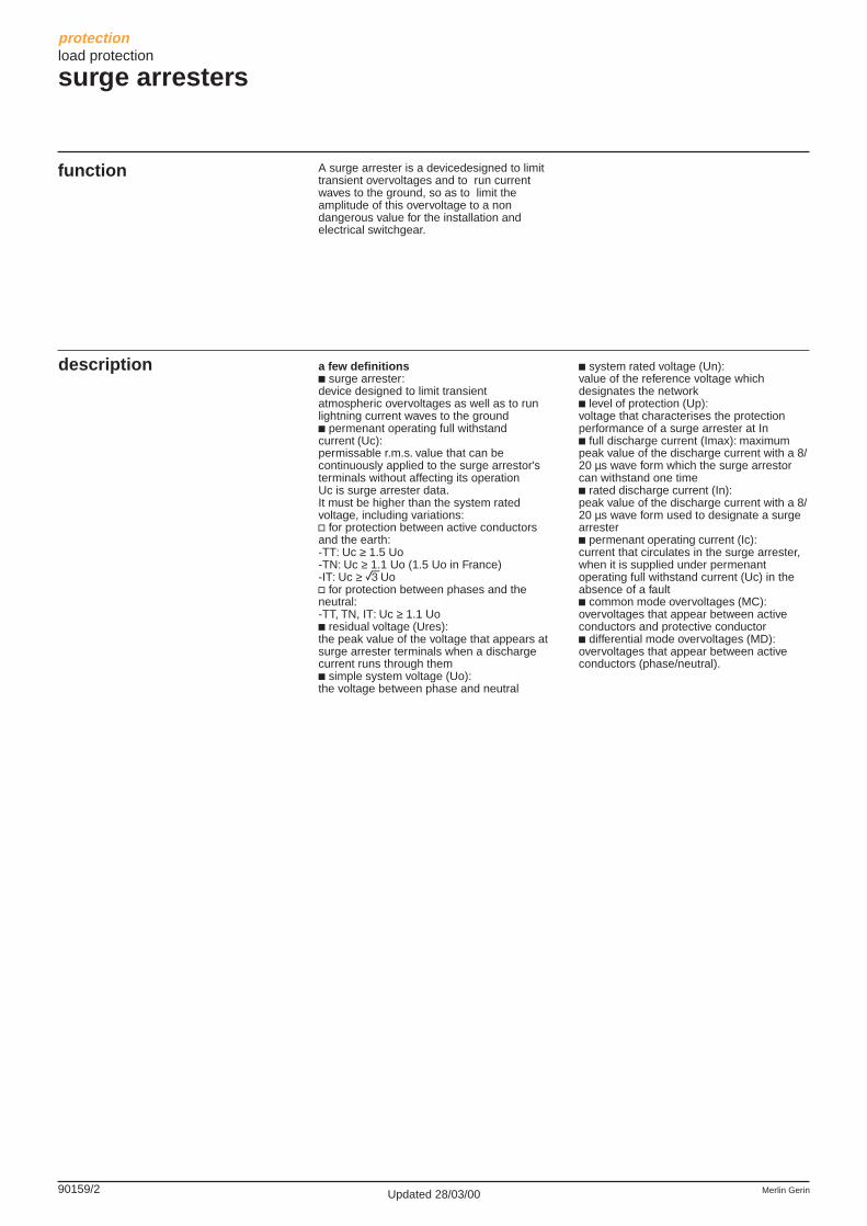
A surge arrester is a devicedesigned to limittransient overvoltages and to run currentwaves to the ground, so as to limit theamplitude of this overvoltage to a nondangerous value for the installation andelectrical switchgear.
protectionload protection
surge arresters
a few definitionsc surge arrester:device designed to limit transientatmospheric overvoltages as well as to runlightning current waves to the groundc permenant operating full withstandcurrent (Uc):permissable r.m.s. value that can becontinuously applied to the surge arrestor'sterminals without affecting its operationUc is surge arrester data.It must be higher than the system ratedvoltage, including variations:v for protection between active conductorsand the earth:-TT: Uc ≥ 1.5 Uo-TN: Uc ≥ 1.1 Uo (1.5 Uo in France)-IT: Uc ≥ eUov for protection between phases and theneutral:-TT, TN, IT: Uc ≥ 1.1 Uoc residual voltage (Ures):the peak value of the voltage that appears atsurge arrester terminals when a dischargecurrent runs through themc simple system voltage (Uo):the voltage between phase and neutral
c system rated voltage (Un):value of the reference voltage whichdesignates the networkc level of protection (Up):voltage that characterises the protectionperformance of a surge arrester at Inc full discharge current (Imax): maximumpeak value of the discharge current with a 8/20 µs wave form which the surge arrestorcan withstand one timec rated discharge current (In):peak value of the discharge current with a 8/20 µs wave form used to designate a surgearresterc permenant operating current (Ic):current that circulates in the surge arrester,when it is supplied under permenantoperating full withstand current (Uc) in theabsence of a faultc common mode overvoltages (MC):overvoltages that appear between activeconductors and protective conductorc differential mode overvoltages (MD):overvoltages that appear between activeconductors (phase/neutral).

90159/3Merlin Gerin Updated 28/03/00
function PRD removable surge arresters enable therapid replacement of damaged cartridges.Removable surge arresters with indication(PRD 65r, PRD 40r) have visualisation aswell as the remote transfer of "cartridge tobe replaced" information.the Uc voltage depends on:c the earthing systemc the protection mode (MC/MD).
description
protectionload protection
PRD draw-out surge arresters
Each surge arrester in the range has aspecific use:c Incomer end protection:v the PRD 65r is recommended for a veryhigh risk level (highly exposed site)v PRD 40r/PRD 40 are recommended for ahigh risk levelv the PRD 15 is recommended for a low risklevelc secondary protection:v the PRD 8 ensures secondary protectionof loads to be protected and is placed in acascading configuration with surge arrestersat the incomer end.
common technical data for PRDsc frequency: 50…60 Hzc Ic:v 1P et 3P: < 800 µAv 1P+N and 3P+N: 0 µAc operation indication by means of amechanical indicator:v white: normal operationv white/red: cartridge replacement to bescheduled in the near futurev red: cartridge must be immediatelyreplacedc disconnection of the short-circuited surgearrester to be conducted with acircuit-breaker (refer to choice table page92506/2)c permissible internal short-circuit current forPRD 8 and PRD 15:v 1P+N, 3P and 3P+N: 10 kAv 1P (230 V): 10 kAv 1P (400): 3 kAc permissible internal short-circuit current forPRD 40 and PRD 65:v 1P+N, 3P and 3P+N: 25 kAv 1P (230 V): 10 kAv 1P (400): 3 kAc downstream and upstream terminalconnection:v 2.5 to 16 mm2 flexible cablev 2.5 to 25 mm2 rigid cablev ≥10 mm2 flexible or rigid cable ifinstallation with lightning conductorc operating temperature:-25 °C, +60 °Cc storage temperature:-40 °C, +70 °Cc protection class:v IP20 at terminalsv IP40 on front panelc weight (g):v 1P: 90v 1P+N: 180v 3P: 395v 3P+N: 460.
standardsc IEC 61643-11 class 2 testc NF C 61740/95.
specific technical data
PRD 65rc Imax (8/20 µs): 65 kAc In (8/20 µs): 20 kAc operating back-up indicatoron front panelc remote indication contact:v electrical data:DC: 12 V, ≥ 10 mAAC: 250 V, ≤ 1 Av connection using 0.5 mm2 to 1.5 mm2
cable.
PRD 40r/PRD 40c Imax (8/20 µs): 40 kAc In (8/20 µs): 15 kAc the PRD 40r includes:v operating back-up indicator on front panelv remote indication contact:- electrical data:DC: 12 V, ≥ 10 mAAC: 250 V, ≤ 1 A- connection using 0.5 mm2 to 1.5 mm2
cable.
PRD 15c Imax (8/20 µs): 15 kAc In (8/20 µs): 5 kA.
PRD 8c Imax (8/20 µs): 8 kAc In (8/20 µs): 2 kA.
spare cartridgesc 40, 15, 8 kA and neutral cartridgesc the C65r, C40r and C neutral r cartridgeshave operating back-up.
auxiliariesc adaptable remote indication modules, EM/RM (see 90159/15).

90159/4 Merlin GerinUpdated 28/03/00
16558
type Un Uc (V) Up cat. no. width(V) MC (kV) in mod.
of 9 mmPRD
1P PRD 65r 230 440 2 16555 2230 275 1.5 16556 2
PRD 40r 230 440 1.8 16560 2230 275 1.2 16561 2
PRD 40 230 440 1.8 16565 2230 275 1.2 16566 2
PRD 15 230 440 1.8 16570 2230 275 1.2 16571 2
PRD 8 230 440 1.8 16575 2230 275 1.2 16576 2
type Un Uc (V) Up cat. no. width(V) MC/MD (kV) in mod.
of 9 mmPRD
1P+N PRD 65r 230 440/275 1.2 (1) 16557 4PRD 40r 230 440/275 1.2 16562 4PRD 40 230 440/275 1.2 16567 4PRD 15 230 440/275 1.2 16572 4PRD 8 230 440/275 1.2 16577 4
(1) Up: L/ =1.5L/N=1.5
type Un Uc (V) Up cat. no. width(V) MC (kV) in mod.
of 9 mmPRD
3P PRD 65r 400 440 2 16558 6PRD 40r 400 440 1.8 16563 6PRD 40 400 440 1.8 16568 6PRD 15 400 440 1.8 16573 6PRD 8 400 440 1.8 16578 6
catalogue numbers
16555
L
16572
LN
N L
L2L1
L3
L1 L2 L3
protectionload protection
PRD draw-out surge arresters

90159/5Merlin Gerin Updated 28/03/00
protectionload protection
PRD draw-out surge arresters
type Un Uc (V) Up cat. no. width(V) MC/MD (kV) in mod.
of 9 mmPRD
3P+N PRD 65r 400 440/275 1.2 (1) 16559 8PRD 40r 400 440/275 1.2 16564 8PRD 40 400 440/275 1.2 16569 8PRD 15 400 440/275 1.2 16574 8PRD 8 400 440/275 1.2 16579 8
(1) Up: L/ =1.5L/N=1.5
type Uc (V) Up cat. no. widthMC (kV) in mod.
of 9 mmcartridges
C65r-440 440 2 16580 2C65r-275 275 1.5 16581 2C40r-440 440 1.8 16582 2C40r-275 275 1.2 16583 2C40-440 440 1.8 16584 2C40-275 275 1.2 16585 2C15-440 440 1.8 16586 2C15-275 275 1.2 16587 2C8-440 440 1.8 16588 2C8-275 275 1.2 16589 2C neutral r 440 1.2 16590 2C neutral 440 1.2 16591 2
catalogue numbers
L1N
L2L3
L3L2L1N16559
16580
90159/6 Merlin GerinUpdated 28/03/00
protectionload protection
PF surge arresters
function
description
The PF all-contained, multiple pole surgearrester range is especially adapted to TT,TN-S and IT earthing systems.PF surges arresters with indication (PF65rand PF30r) have visualisation as well asremote transfer of "cartridge to be replaced"information.
common technical datac frequency: 50…60 Hzc max. leakage current < 200 µAc operation indication by means of anorange indicator:v not lit: okv flashing: surge arrester must beimmediately replacedc disconnection upon thermal overload built-into the surge arresterc disconnection of the short-circuited surgearrester to be conducted with a circuit-breaker (refer to choice table page 92506/2)c permissible internal short-circuitcurrent for PF8 and PF15:v 1P+N and 3P+N: 10 kAc permissible internal short-circuitcurrent for PF30 and PF65:v 1P+N and 3P+N: 25 kAc operating temperature:-25 °C to +60 °Cc storage temperature:-40 °C to +70 °Cc protection class:v IP20 at terminalsv IP40 on front panelc weight (g):v 1P+N: 475v 3P+N: 650.
standardc NF C 61740/95.specific technical data
PF65rc common mode protection:v Imax (8/20 µs): 65 kAv In (8/20 µs): 20 kAv Up: 2 kVc test button for front panel indicatorc remote indication contact:v normally closedv connection using tunnel terminals2 x 2.5 mm2
c connection using tunnel terminals:v phase and neutral: 25 mm2
v earth: 50 mm2.v flexible or rigid cable ≥10 mm2 ifinstallation using lightning conductor.
PF30r and PF30c common mode protection:v Imax (8/20 µs): 30 kAv In (8/20 µs): 10 kAv Up: 1.8 kVc test button for front panel indicatorc the PF30r has a built-in remote indicationcontact:v normally closedv connection using tunnel terminals2 x 2.5 mm2
c connection using tunnel terminals:v phase and neutral: 25 mm2
v earth: 50 mm2.v flexible or rigid cable ≥10 mm2 ifinstallation using lightning conductor.
PF15c common mode protection:v Imax (8/20 µs): 15 kAv In (8/20 µs): 5 kAv Up: 1.8 kVc differential mode protection:v Imax (8/20 µs): 8 kAv In (8/20 µs): 2 kAv Up: 1 kVc connection using tunnel terminals:v phase and neutral: 16 mm2
v earth: 25 mm2.v flexible or rigid calbe ≥10 mm2 ifinstallation using lightning conductor.
PF8c common mode protection:v Imax (8/20 µs): 8 kAv In (8/20 µs): 2 kAv Up: 1.5 kVc differential mode protection:v Imax (8/20 µs): 8 kAv In (8/20 µs): 2 kAv Up: 1 kVc connection using tunnel terminals:v phase and neutral: 16 mm2
v earth: 25 mm2.v flexible or rigid cable ≥10 mm2 ifinstallation using lightning conductor.
Each surge arrestor in the range has aspecific use:c incomer end protection:v the PF65r is recommended for a very highrisk level (highly exposed site)v PF30r/PF30 are recommended for a highrisk levelv the PF15 is recommended for a low risklevelc secondary protection:v the PF8 ensures the secondary protectionof loads to be protected and is placed in acascading configuration with surge arrestorsat the incomer end.
90159/7Merlin Gerin Updated 28/03/00
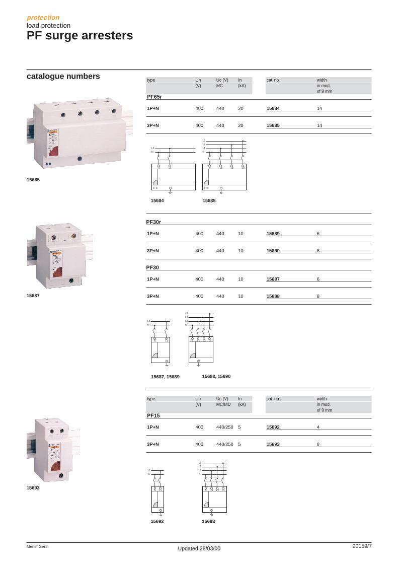
type Un Uc (V) In cat. no. width(V) MC (kA) in mod.
of 9 mmPF65r
1P+N 400 440 20 15684 14
3P+N 400 440 20 15685 14
PF30r
1P+N 400 440 10 15689 6
3P+N 400 440 10 15690 8
PF30
1P+N 400 440 10 15687 6
3P+N 400 440 10 15688 8
type Un Uc (V) In cat. no. width(V) MC/MD (kA) in mod.
of 9 mmPF15
1P+N 400 440/250 5 15692 4
3P+N 400 440/250 5 15693 8
catalogue numbe rs
L2
L3
L1
N
N L 1 L 2 L 3
L1
N
N L 1
L1
N
N L 1
15684 15685
15687, 15689 15688, 15690
L1
N
N L 1
15692 15693
L2
L3
L1
N
N L 1 L 2 L 3
L2
L3
L1
N
N L 1 L 2 L 3
15685
15687
15692
protectionload protection
PF surge arresters
90159/8 Merlin GerinUpdated 28/03/00
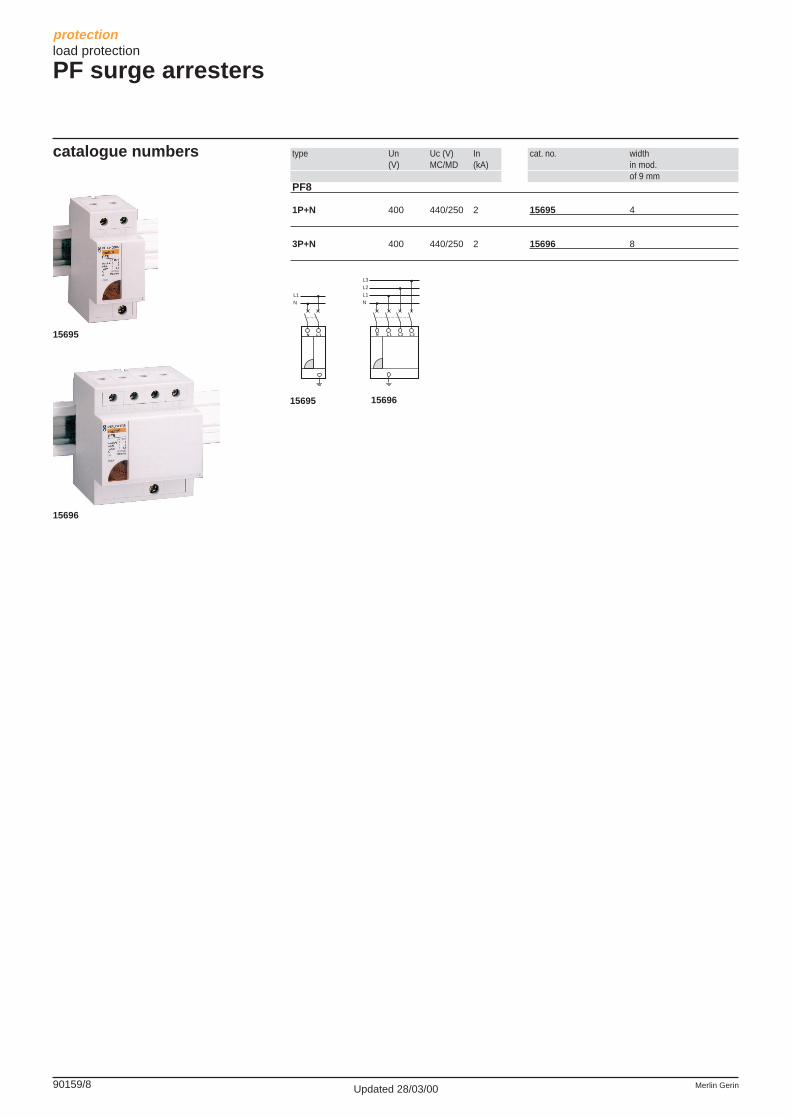
type Un Uc (V) In cat. no. width(V) MC/MD (kA) in mod.
of 9 mmPF8
1P+N 400 440/250 2 15695 4
3P+N 400 440/250 2 15696 8
L1
N
N L 1
15695 15696
catalogue numbe rs
L2
L3
L1
N
N L 1 L 2 L 315695
15696
protectionload protection
PF surge arresters

90159/9Merlin Gerin Updated 28/03/00
protectionload protection
PE surge arrestersTN-C and IT earthing systems
function
description
The 4 PE surge arresters are particularlyadapted to earthing systems: TN-C and IT.
Each surge arrester in the range has aspecific use:c incomer end protection:v the PE65 is recommended for a very highrisk level (highly exposed site)
common technical datac frequency: 50…60 Hzc Uc: permanent operating full withstandcurrent: 440 Vc Ic: permanent operating current: < 1 mAc disconnection of short-circuited surgearrester to be conducted with a circuit-breaker (refer to choice table page 92506/2)c permissible internal short-circuitcurrent: 3 kAc connection using tunnel terminals:v phase, neutral and earth: 25 mm2 rigid and16 mm2 flexiblec min. phase/neutral/earth cross-section:v 4 mm2 without lightning conductorv 10 mm2 with lightning conductorc protection class:v IP20 at terminalsv IP40 on front panelc operating temperature:-25 °C, +60 °Cc storage temperature:-40 °C, +70 °Cc weight (g):v PE8: 130v PE15: 130v PE40: 138v PE65: 166.
standardc NF C 61740/95.
specific technical data
v the PE40 is recommended for a high risklevelv the PE15 is recommended for a low risklevelc secondary protection:v the PE8 ensures the secondary protectionof loads to be protected and is placed in acascading configuration with the surgearresters at the incomer end.
PE65c Imax (8/20 µs): 65 kAc In (8/20 µs): 20 kAc Up: 2 kVc operation indication by means of amechanical indicator:v white: normal operationv white/red: surge arrester replacement tobe scheduled in the near futurev red: surge arrester must be immediatelyreplaced.
PE40c Imax (8/20 µs): 40 kAc In (8/20 µs): 10 kAc Up: 1.8 kVc operation indication by means of amechanical indicator:v white: normal operationv red: surge arrester must be immediatelyreplaced.
PE15c Imax (8/20 µs): 15 kAc In (8/20 µs): 5 kAc Up: 1.8 kVc operation indication by means of amechanical indicator:v white: normal operationv red: surge arrester must be immediatelyreplaced.
PE8c Imax (8/20 µs): 8 kAc In (8/20 µs): 2 kAc Up: 1.5 kVc operation indication by means of amechanical indicator:v white: normal operationv red: surge arrester must be immediatelyreplaced.
auxiliariesc adaptable remote indication modules, EM/RM (see 90159/15).

90159/10 Merlin GerinUpdated 28/03/00
protectionload protection
PE surge arrestersTN-C and IT earthing systems
type Un Uc (V) In cat. no. width(V) MC (kA) in mod.
of 9 mmPE
PE65 400 440 20 15683 2PE40 400 440 10 15686 2PE15 400 440 5 15691 2PE8 400 440 2 15694 2
catalogue numbers
15683
15683
MERLIN GERIN
multi 9PE65Imax 65kA (8/20)
100kA (4/10)In 20kA (8/20)Up 2 kVUc 440V
if redreplace
L/N
15683
MERLIN GERIN
multi 9PE65Imax 65kA (8/20)
100kA (4/10)In 20kA (8/20)Up 2 kVUc 440V
if redreplace
L
N
or

90159/11Merlin Gerin Updated 28/03/00
protectionload protection
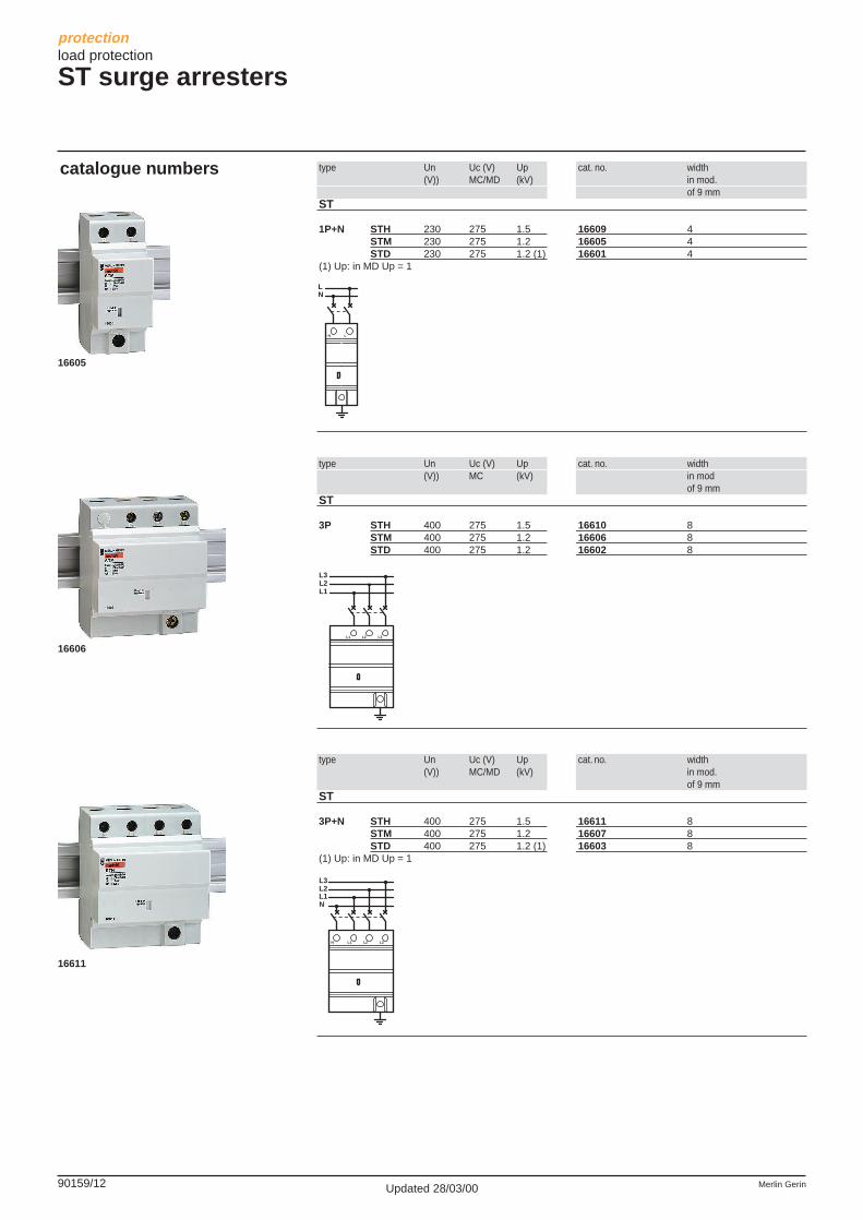
ST surge arresters
function
description
catalogue numbers
ST surge arresters are designed to protectequipment on energy networks using TN-Sand TN-C earthing systems. They are notrecommended on TT systems and areforbidden on IT systems.Each surge arrester in the range has aspecific use:
type Un Uc (V) Up cat. no. width(V)) MC (kV) in mod.
of 9 mmST
1P STH 230 275 1.5 16608 2STM 230 275 1.2 16604 2STD 230 275 1.2 16600 2
16608
common technical datac frequency: 50…60 Hzc Uc: 275 Vc operation indication by means of amechanical indicator:v white: normal operationv red: surge arrester must be immediatelyreplacedc disconnection of the short-circuited surgearrester to be conducted with a circuit-breaker (refer to choice table page 92506/2)c permissible internal short-circuitcurrent for STD: 10 kAc permissible internal short-circuitcurrent for STM and STH:v 1P+N, 3P and 3P+N: 25 kAv 1P: 10 kAc upstream and downstream terminalconnection:v flexible cable: 2.5 to 16 mm2
v rigid cable: 2.5 to 25 mm2
v flexible or rigid cable ≥10 mm2 ifinstallation with lightning conductorc operating temperature:-25 °C, +60 °Cc storage temperature:-40 °C, +70 °Cc protection class:v IP20 at terminalsv IP40 on front panelc weight (g):v 1P: 60v 1P+N: 106v 3P: 220v 3P+N: 250.
standardv IEC 61643-11 class 2 test.
specific technical data
STHc common mode protection:v Imax (8/20 µs): 65 kAv In (8/20 µs): 20 kAv Up: 1.5 kV.
STMc common mode protection:v Imax (8/20 µs): 40 kAv In (8/20 µs): 15 kAv Up: 1.2 kV.
STDc common mode protection:v Imax (8/20 µs): 10 kAv In (8/20 µs): 5 kAv Up: 1.2 kVc differential mode protection:v Imax (8/20 µs): 10 kAv In (8/20 µs): 3 kAv Up: 1 kV.
auxiliariesc adaptable remote indication modules, EM/RM (see 90159/15).
c incomer end protection:v the STH is recommended for a very highrisk level (highly exposed site)v STMs are recommended for a high risklevelc secondary protection:v the STD ensures secondary protection ofloads to be protected and is placed in acascading configuration with surge arrestersat the incomer end.
L
L
90159/12 Merlin GerinUpdated 28/03/00
type Un Uc (V) Up cat. no. width(V)) MC/MD (kV) in mod.
of 9 mmST
1P+N STH 230 275 1.5 16609 4STM 230 275 1.2 16605 4STD 230 275 1.2 (1) 16601 4
(1) Up: in MD Up = 1
type Un Uc (V) Up cat. no. width(V)) MC (kV) in mod
of 9 mmST
3P STH 400 275 1.5 16610 8STM 400 275 1.2 16606 8STD 400 275 1.2 16602 8
type Un Uc (V) Up cat. no. width(V)) MC/MD (kV) in mod.
of 9 mmST
3P+N STH 400 275 1.5 16611 8STM 400 275 1.2 16607 8STD 400 275 1.2 (1) 16603 8
(1) Up: in MD Up = 1
catalogue numbers
protectionload protection
ST surge arresters
16606
16611
L2L1
L2
L3
L1 L3
L2L1
L2
L3
N
L1 L3N
16605
LN
N L
90159/13Merlin Gerin Updated 28/03/00
protectionload protection
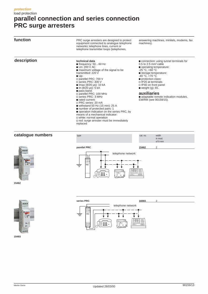
parallel connection and series connectionPRC surge arresters
function
description
PRC surge arresters are designed to protectequipment connected to analogue telephonenetworks: telephone lines, current ortelephone transmitter loops (telephones,
technical datac frequency: 50…60 Hzc Un: 200 V ACc maximum voltage of the signal to betransmitted: 220 Vc Up:v parellel PRC: 700 Vv series PRC: 300 Vc Imax (8/20 µs): 10 kAc In (8/20 µs): 5 kAc pass-band:v parellel PRC: 100 MHzv series PRC: 3 MHzc rated current:v PRC series: 20 mAc withstand 50 Hz (15 min): 25 Ac number of protected pairs: 1c operation indication on the series PRC, bymeans of a mechanical indicator:v white: normal operationv red: surge arrester must be immediatelyreplaced
answering machines, minitels, modems, faxmachines).
c connection: using tunnel terminals for0.5 to 2.5 mm2 cablec operating temperature:-25 °C, +60 °Cc storage temperature:-40 °C, +70 °Cc protection class:v IP20 at terminalsv IP40 on front panelc weight (g): 65.
auxiliariesc adaptable remote indication modules,EM/RM (see 90159/15).
catalogue numbers type cat. no. widthin mod.of 9 mm
parellel PRC 15462 2
series PRC 16593 2
15462
15493
1
telephon network
PRC
3 5
24 6 FE
GBI
NL/B
16420
MERLIN GERIN
TRC1mult i 9
telephone network
FE
GBI
NL/B
16420
MERLIN GERIN
TRC1mult i 9
1
telephon network
PRC
3 5
telephone network
90159/14 Merlin GerinUpdated 28/03/00
protectionload protection
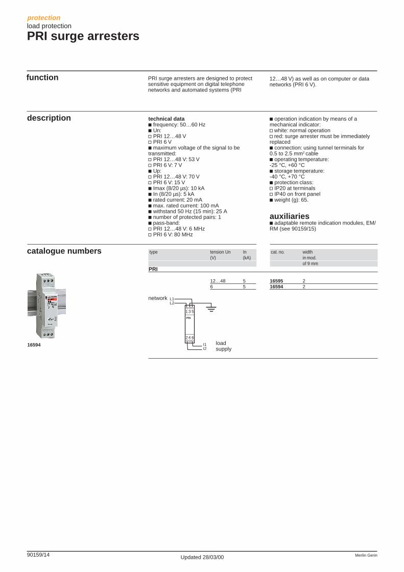
PRI surge arresters
function
description
catalogue numbers
PRI surge arresters are designed to protectsensitive equipment on digital telephonenetworks and automated systems (PRI
technical datac frequency: 50…60 Hzc Un:v PRI 12…48 Vv PRI 6 Vc maximum voltage of the signal to betransmitted:v PRI 12…48 V: 53 Vv PRI 6 V: 7 Vc Up:v PRI 12…48 V: 70 Vv PRI 6 V: 15 Vc Imax (8/20 µs): 10 kAc In (8/20 µs): 5 kAc rated current: 20 mAc max. rated current: 100 mAc withstand 50 Hz (15 min): 25 Ac number of protected pairs: 1c pass-band:v PRI 12…48 V: 6 MHzv PRI 6 V: 80 MHz
type tension Un In cat. no. width(V) (kA) in mod.
of 9 mmPRI
12…48 5 16595 26 5 16594 2
16594
c operation indication by means of amechanical indicator:v white: normal operationv red: surge arrester must be immediatelyreplacedc connection: using tunnel terminals for0.5 to 2.5 mm2 cablec operating temperature:-25 °C, +60 °Cc storage temperature:-40 °C, +70 °Cc protection class:v IP20 at terminalsv IP40 on front panelc weight (g): 65.
auxiliariesc adaptable remote indication modules, EM/RM (see 90159/15)
12…48 V) as well as on computer or datanetworks (PRI 6 V).
network
loadsupply
1
PRI
3 5
24 6
I1I2
L1L2

90159/15Merlin Gerin
additionalinformation
dimensions: page 90148/2practical advice: page 92506/2
Updated 28/03/00
protectionload protection
EM/RM remote indication modules
function
description
catalogue numbers
The adaptable EM/RM remote indicationmodules are made up of two optical blocks,a transmitter and a receiver. They aredesigned to remotely signal the transfer toback-up or the disconnection of thecombined surge arresterc the EM transmitter is mounted to the leftand the RM receiver to the right side of aPRD, PE, PRC, PRI, STH, STM or STD
type cat. no. widthin mod.of 9 mm
remode indication module
EM/RM 16592 2+2
technical datac voltage rating: 230 V ACc frequency: 50…60 Hzc surge arrester status indication: by meansof green and red indicators on the frontpanelc output contact:v NO/NC (closed between terminals 2 and 4if fault on surge arrester)v min. power: 6 V DC and 10 mAv max. power: 250 V AC and 5 Av insulation between contacts: 1 kV ACv insulation between the contacts and thecoil: 2.5 kV AC
surge arrester.c the RM receiver has an output contact forthe remote transfer of surge arresterdisconnection informationc the module can monitor up to 15 surgearrester modules (18 mm) with a limit of 270mm.
c flexible or rigid cable connection:v up to 2.5 mm2
c operating temperature:-20 °C, +40 °Cc storage temperature:-40 °C, +70 °Cc weight (g): 20.
16592
LN
1 3 5 1 3 5
2 4 6