effect of diameter ratio and inclination angle on air
TRANSCRIPT
Applied Engineering Letters Vol.5, No.1, 22-30 (2020) e-ISSN: 2466-4847
*CONTACT: G.K. Makrygiannis, e-mail: [email protected] © 2019 Published by the Serbian Academic Center
EFFECT OF DIAMETER RATIO AND INCLINATION ANGLE ON AIR-WATER SEPARATION OCCURRED AT A SMALL DIAMETER T-JUNCTION
UDC: 696.133.1:519.6 Original scientific paper https://doi.org/10.18485/aeletters.2020.5.1.4
Georgios K. Makrygiannis1*, Dionissios P. Margaris1
1University of Patras, Mechanical Engineering and Aeronautics Department, Fluid Mechanics Laboratory, Patras, Greece
Abstract: The simple geometry configuration of T-junctions and their capability to act as partial phase separators, especially on offshore platforms, made them common pipeline system components in power and process industries. Moreover, in the pursuit of achieving better phase separation by controlling the maldistribution occurred in the component phases of a mixture at the junction, industries often utilise reduced T-junctions. Nevertheless, most of the published data in which industries was based on to adopt the previous configuration was relating on fully horizontal T-junctions with large main pipe diameters although T-junctions are rarely placed in a horizontal position in such industries, whilst the usage of small main pipe diameters could also lead to scaling down their size. In this regard, the present paper aimed to extend the available data by performing numerical analysis and studying both regular and reduced T-junctions with a small main pipe diameter, and upward inclination angles. It was observed that reduced T-junctions performed worse in terms of phase separation compared to regular T-junctions for all inlet conditions applied and irrespective of the side arm inclination, whereas in case of regular T-junctions a superior separation performance was ensured for the inclined side arm at 30°.
ARTICLE HISTORY Received: 05.02.2020. Accepted: 27.02.2020. Available: 31.03.2020.
KEYWORDS T-junction, inclination angle, diameter ratio, phase separation, water carryover
1. INTRODUCTION
T-junctions are common pipeline system components in power and process industries. Despite their simple geometry configuration which is consisted of one inlet and two outlets, they are utilised in a great extent for the distribution of fluids in the above industries [1]. Depending on the inlet configuration, T-junctions can be classified into two main classes, and thus there are branching and impacting T-junctions [2]. In case of branching T-junctions, the mixture phases flow through their main arm and branching out upon reaching the junction, while in impacting T-junctions the incoming fluids are introduced from the side arm of the junction [3].
The operating principle in case of T-junctions employed in power and process industries is based
on the maldistribution occurred in the component phases of a gas-liquid mixture passed through a junction. This uneven splitting behavior of the incoming phases was firstly reported by Oranje [4] and its existence is due to the momentum difference of the mixture phases which causes the lighter phase to enter the side arm of the junction, and the heavier phase to continue its flow into the run arm [5].
The phase separation capabilities of T-junctions made them a common part in processing industries, especially on offshore platforms, where the safety of the overall production process is of a great importance [6]. More specifically, they act as supplementary equipment to the conventional separators which are both bulky structures and hazardous due to the presence of a large inventory of flammable materials [7].
G.K. Makrygiannis and D.P. Margaris / Applied Engineering Letters Vol.5, No.1, 22-30 (2020)
23
In order to improve the separation performance of T-junctions, and thus reduce the maldistribution of the mixture phases that has a significant effect on the downstream equipment as well [8], it is important to understand the behavior of the gas-liquid two-phase separation phenomenon. The understanding of the separation process is quite complicated due to the large number of variables that affect it, such as the geometry of the junction, the existing flow pattern upstream of the junction, and the gas and liquid flow rates. It is indicative of the described complexity that a definition of eight parameters is required just to specify the geometrical characteristics of the T-junction according to Rea and Azzopardi [9], while among these characteristics the most important is probably the side to main arm diameter ratio [10] that affects not only the pressure profile inside the junction [11], but also the time and the axial distance that is available for the liquid carryover process [12]. Apart from side to main arm diameter ratio, both inclination angle and orientation of the T-junction branch affects the forces govern the separation phenomenon which are the inertial, the centripetal, and the gravitational forces as stated by Hong [8]. For example, the gravitational force in case of an upward inclined branch assists the deterioration of the liquid carryover emerge on that branch compared to the liquid carryover drawn off in case of a downward oriented T-junction branch [13].
The potential, therefore, to benefit from this unequal split of a two-phase flow approaching a T-junction, the simplicity of its structure, and the complexity of predicting accurately the separation phenomenon has gained the attention of the research community.
Most of the studies conducted in the past decades were concentrated mainly on regular and fully horizontal T-junctions although their location in power and process industries is rarely regular and horizontal. In addition, a fully horizontal T-junction does not perform well as phase separator according to the findings of Yang and Azzopardi [14] who studied experimentally a regular, uniform, and horizontal T-junction with a diameter of 67.4 mm. Thus, the research community was focused next on studying reduced T-junctions. Shoham et al. [15] compared the separation occurred in horizontal, regular, and reduced T-junctions and they found that better performance in terms of phase separation is achieved by decreasing the diameter ratio. Same results obtained from the studies of Azzopardi [16], Wren [17], and Wren and Azzopardi [18], while the findings of Griston and Choi [19]
work suggested that the ameliorated phase separation of a reduced T-junction is irrespective of the working phases’ nature. On the contrary, the findings of Walters et al. [20] who studied a T-junction with a main arm diameter of 38.1 mm suggest that a large decrement in diameter ratio (0.206) of a T-junction can lead to a worse performance even in comparison with a regular T-junction.
The researchers first studied an inclined T-junction branch were Seeger et al. [21] who performed experiments for three different inclination angles: horizontal, upward, and downward vertical branch arms. Later, Penmatcha [22] and Ashton [23] conducted similar experimental studies to investigate the two-phase flow split at a downward and upward inclined T-junction branch, respectively. The working fluids were air and water and the regular T-junction tested had a diameter of 50.1 mm. The effect of inclination angle was also studied by Marti and Shoham [11] who tested a reduced T-junction (diameter ratio of 0.5) with a main arm diameter of 51 mm for various upward (+1°, +5°, +10°, +20°) and downward (-5°, -10°, -25°, -40°, -60°) inclination angles. They found that the gravitational force has a key role in phase separation by reducing or enhancing the liquid carryover depending on the orientation of the T-junction branch. The significance of the gravitational force in two-phase separation was also reported by Penmatcha et al. [24] who conducted experiments for a regular T-junction tilted at various upward (+1°, +5°, +10°, +20°, +35°) and downward (-5°, -10°, -25°, -40°, -60°) inclination angles.
Based on the previous literature findings, today most of the power and process industries adopt reduced T-junctions in order to enhance the phase separation capabilities although the findings of Walters et al. [20] raise significant concerns. Moreover, there is obviously a lack of published data regarding the study of small diameter T-junctions which are of great interest since they can lead to scaling down the size of industries manufacture or process hazardous materials according to Stacey et al. [25]. In this perspective, the present work intends to complement the available data by studying both regular and reduced T-junctions with a small main arm diameter, and upward inclination angles. 2. COMPUTATIONAL MODEL
This analysis was performed on Ansys Fluent
software which is a commercial computational fluid

G.K. Makrygiannis and D.P. Margaris / Applied Engineering Letters Vol.5, No.1, 22-30 (2020)
24
dynamics software providing the ability to resolve complex flow phenomena in a robust, accurate and fast manner. More specifically, the geometries and the corresponding computational meshes were generated on the Design Modeler and the Ansys Meshing applications of the software, whilst the required simulations were carried out in Fluent.
The main and run arm pipes of both regular and reduced T-junctions were placed in a horizontal position and they had a diameter of 20 mm, while their side arm was positioned in two different upward inclination angles: 30° and 90°. Whereas, in case of reduced T-junctions two distinct diameter ratios were examined: 1.0 and 0.5. The diameter ratio can be defined as:
𝐷𝑅 =𝐷3
𝐷1 (1)
where D3 and D1 correspond to the side and main arm diameters, respectively. Fig.1 depicts both regular and reduced T-junctions with the side arm tilted at 30°, while the major dimensions of the computational models created are tabulated on Table 1.
Fig.1. (a) Reduced and (b) regular T-junction geometries created with the side arm tilted at 30°
Table 1. Main dimensions of the generated computational models
Section of computational geometry Dimension
(mm) Pipe diameter 20
Main arm pipe length 700
Run arm pipe length 300
Length of inclined T-junction branch 300
Overall length 1100
The computational mesh in all test cases
examined was a hybrid one consisted of approximately 500,000 hexahedral and tetrahedral elements, Fig.2, and it was generated taking into consideration the applied turbulence closure method and the desired y+ value in order to be both reliable in terms of the extracted results and
consistent with the applied turbulence model, while its final dense was yielded after performing a mesh independence study [26].
Fig.2. Zoom-in the area of T-junction illustrating the computational mesh generated for conducting the
numerical study
Regarding the simulation setup settings summarized in Table 2, a transient, turbulent air-water two-phase flow was considered. The Volume of Fluid (VOF) was set as the multiphase model, while the closure of turbulence was achieved by utilising the Realizable k-ε turbulence model. The latter was employed based on its satisfactorily performance that in the meanwhile requires less computing power in comparison with other available turbulence models such as the Standard k-ω and the SST k-ω models constituting therefore a common practice according to literature [27, 28], and due to the findings reported that the choice of the turbulence model affects less the accurate results in terms of predicting the phases’ redistribution [29]. Concerning the discretization schemes, the Body Force Weighted scheme was used for the pressure discretization and the Compressive scheme for the volume of fluid, while the Second Order Upwind scheme was utilised for the remaining variables. Finally, the transient time formulation was achieved by applying the Bounded Second Order Implicit Scheme, while the pressure and velocity fields were coupled using the PISO algorithm.
Table 2. Simulation setup settings applied in all test cases
Setup settings
Solver type Pressure-based
Transient formulation Bounded second order
implicit
Turbulence model Realizable k-ε
Pressure-velocity coupling PISO
Volume fraction Compressive
Pressure Body force weighted
Momentum Second order upwind
Turbulent kinetic energy Second order upwind
Turbulent dissipation rate Second order upwind

G.K. Makrygiannis and D.P. Margaris / Applied Engineering Letters Vol.5, No.1, 22-30 (2020)
25
2.1 Validation of the computational model
In order to assess the reliability and performance of the generated computational model, a benchmark analysis was carried out. The benchmark cases enlisted in Table 3 were selected from the experimental study of Saieed et al. [3], but due to the larger pipe diameter employed in their experimental apparatus (D=78 mm), the benchmark analysis was performed based on the velocity ratios. The velocity ratio can be defined as follows:
𝑉𝑅 =𝑣𝑆𝐴
𝑣𝑆𝑊 (2)
where vSA and vSW correspond to the superficial velocity of air and water, respectively, namely to the hypothetical flow velocity assuming that these two fluids flow independently of each other inside the pipe. According to the findings reported by Liu and Li [30], the T-junction phase separation is determined by the phase inertia difference and thus by adopting similar velocity ratios different sets of separation data can be compared. Apart from velocity ratios, the established flow regime was ensured to be a stratified-wavy, similar to that observed from Saieed et al. [3] experiments.
Table 3. Air and water superficial velocities and velocity ratios considered in the benchmark cases
Benchmark Cases (BC)
Saieed et al. study Present study
vSA vSW VR vSA vSW
1 0.228 0.094 2.426 4.53 1.77
2 0.228 0.132 1.727 4.53 2.65
3 0.288 0.094 3.064 8.16 2.65
In every benchmark case the fraction of water
emerged in the side arm of the computational model for a given fraction of air was compared with the corresponding value reported by Saieed et al. [3]. Fig.3 depicts the obtained results, where a reasonably good agreement is observed between the two studies. The larger amount of the side arm water fraction intake observed here can be justified according to Stacey et al. [25] since a decrease in the T-junction diameter causes an increase in the water fraction take off.
Fig.3. Comparison between the air and water fractions drawn off the side arm resulted from the present study
and Saieed et al. [3] experiments
3. RESULTS AND DISCUSSION
3.1 Determination of flow regime
The flow regime encountered for each possible
combination of air and water phase velocities shown in Table 4 was determined by applying the Taitel and Dukler horizontal flow map [31]. This flow map first utilises the Martinelli parameter X and the gas Froude number FrG and depending on their values incorporates next the calculation of either parameter K or parameter T. The equations govern the inlet flow regime determination are as follows:
𝑋 = [(𝑑𝑃 𝑑𝑧⁄ )
𝐿
(𝑑𝑃 𝑑𝑧⁄ )𝐺
]
12⁄
(3)
𝐹𝑟𝐺 =�̇�𝐺
[𝜌𝐺(𝜌𝐿−𝜌𝐺)𝐷𝑔]12⁄ (4)
(𝑑𝑃 𝑑𝑧⁄ )𝐿,𝐺
=2𝑓𝐿,𝐺�̇�𝐿,𝐺
2
𝜌𝐿,𝐺𝐷 (5)
𝑓𝐿,𝐺 = 0.079𝑅𝑒𝐿,𝐺−1 4⁄ (6)
𝑅𝑒𝐿,𝐺 =�̇�𝐿,𝐺𝐷
𝜇𝐿,𝐺 (7)
𝑇 = [(𝑑𝑃 𝑑𝑧⁄ )
𝐿
𝑔(𝜌𝐿−𝜌𝐺)]
12⁄
(8)
𝛫 = 𝐹𝑟𝐺𝑅𝑒𝐿12⁄ (9)
where ṁ is the mass flux, ρ is the density, f is the friction factor and Re is the Reynolds number. Whereas, the subscripts L and G denote the corresponding parameter value of either liquid or gas phase of the mixture, respectively.

G.K. Makrygiannis and D.P. Margaris / Applied Engineering Letters Vol.5, No.1, 22-30 (2020)
26
Table 4. Inlet flow conditions applied for the phase separation study of both regular and reduced T-junctions
Test Case (TC)
vSA (m/s)
vSW (m/s)
DR Inclination angle, θ (°)
1 0.957 0.442
0.5, 1.0
30°, 90° 2 0.957 2.65
3 8.16 0.442
4 8.16 2.65
Fig.4. Illustration of the contingent flow regime for the applied inlet conditions according to Taitel and Dukler
horizontal flow map
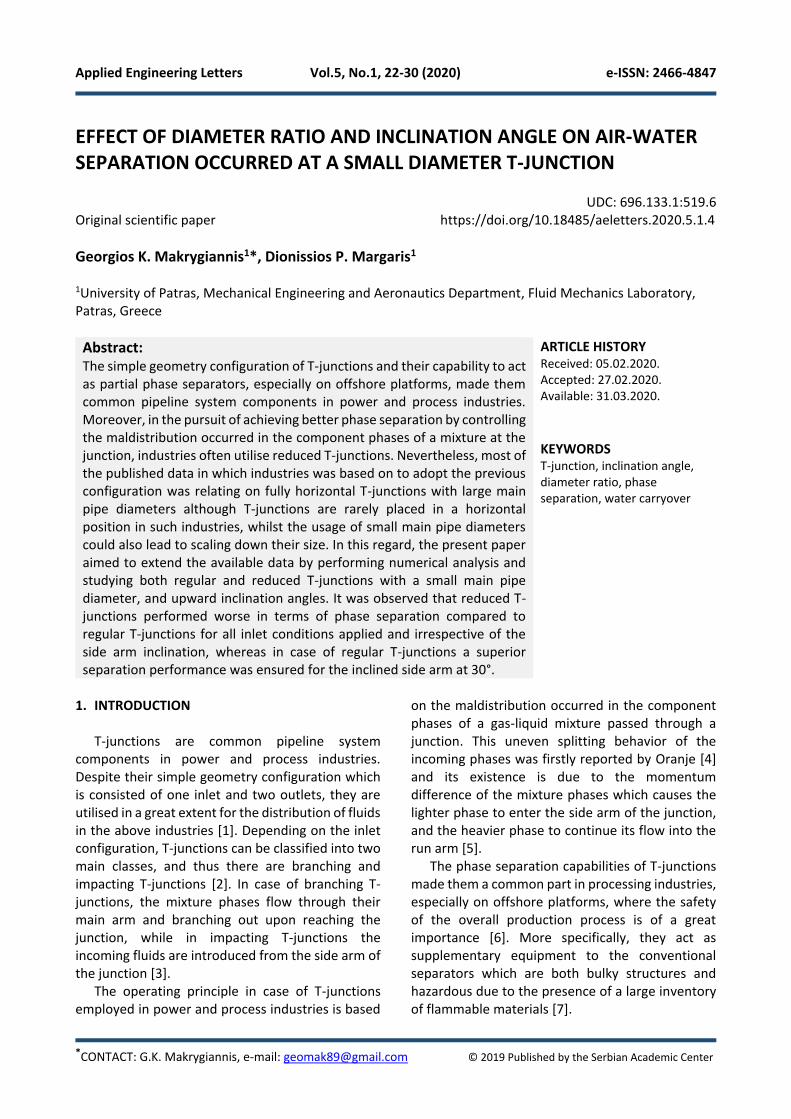
It is obvious from Fig.4 that the resulted flow regime according to the adopted horizontal flow map fall into the intermittent flow region despite that the established flow regime in all numerical studies performed was stratified or stratified-wavy, Figs.5 - 8. This disparity is also experienced by Wren [17] and Saieed et al. [3] and it can be justified due to the flow regime development length that it was available in the computational models. In the present study this length was 35 times the main arm diameter, similar to that adopted by Wren [17] and Saieed et al. [3] which was 32 and 77 times the main pipe diameter, respectively. It is worth to be noted that according to Penmatcha et al. [24] the flow regime development length should be 600 times the main pipe diameter, but it is clearly enough that such a choice would be render the numerical studies non feasible in terms of computational mesh size and required computational time.
Fig.5. Three circular planes along the main horizontal arm illustrating the flow regimes encountered for all test cases examined in case of regular and inclined T-
junctions at 30°
Fig.6. Three circular planes along the main horizontal arm illustrating the flow regimes encountered for all test cases examined in case of upward and vertical
oriented regular T-junctions
Fig.7. Three circular planes along the main horizontal arm illustrating the flow regimes encountered for all
test cases examined in case of reduced and inclined T-junctions at 30°
G.K. Makrygiannis and D.P. Margaris / Applied Engineering Letters Vol.5, No.1, 22-30 (2020)
27
Fig.8. Three circular planes along the main horizontal arm illustrating the flow regimes encountered for all test cases examined in case of upward and vertical
oriented reduced T-junctions
3.2 Regular and reduced T-junctions
The phase separation capabilities of all T-junction geometries and inlet conditions presented in Table 4 were evaluated in terms of separation performance. The separation performance of T-junction can be considered good when it combines both large quantity of air extracted from its side arm in conjunction with low water carryover emerged at that branch.
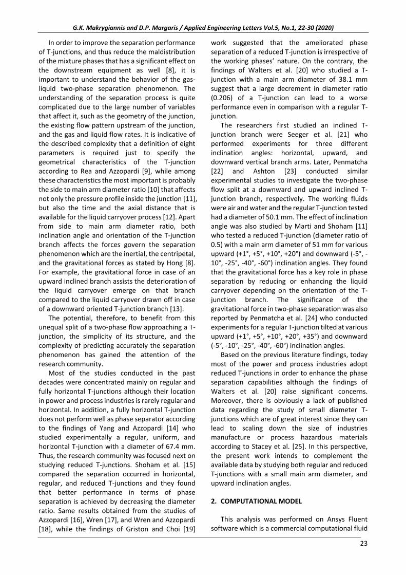
Fig.9 depicts the phase separation obtained in case of regular T-junctions with the side arm tilted at different upward inclination angles. It can be seen that in general the T-junction with the inclined side arm at 30° ensures better operation in almost all test cases examined except TC2. The most important feature is that the phase splitting performance of the T-junction tilted at 30° remains high and almost immutable despite the significant variation of the air and water superficial velocities. On the contrary, the separation performance of the upward and vertical oriented T-junction is extremely depended on the inlet flow conditions and mainly on the air superficial velocity. Moreover, the increase in air superficial velocity causes the water carryover to increase for both T-junctions geometries, fact that is also observed from Saieed et al. [3] experiments.
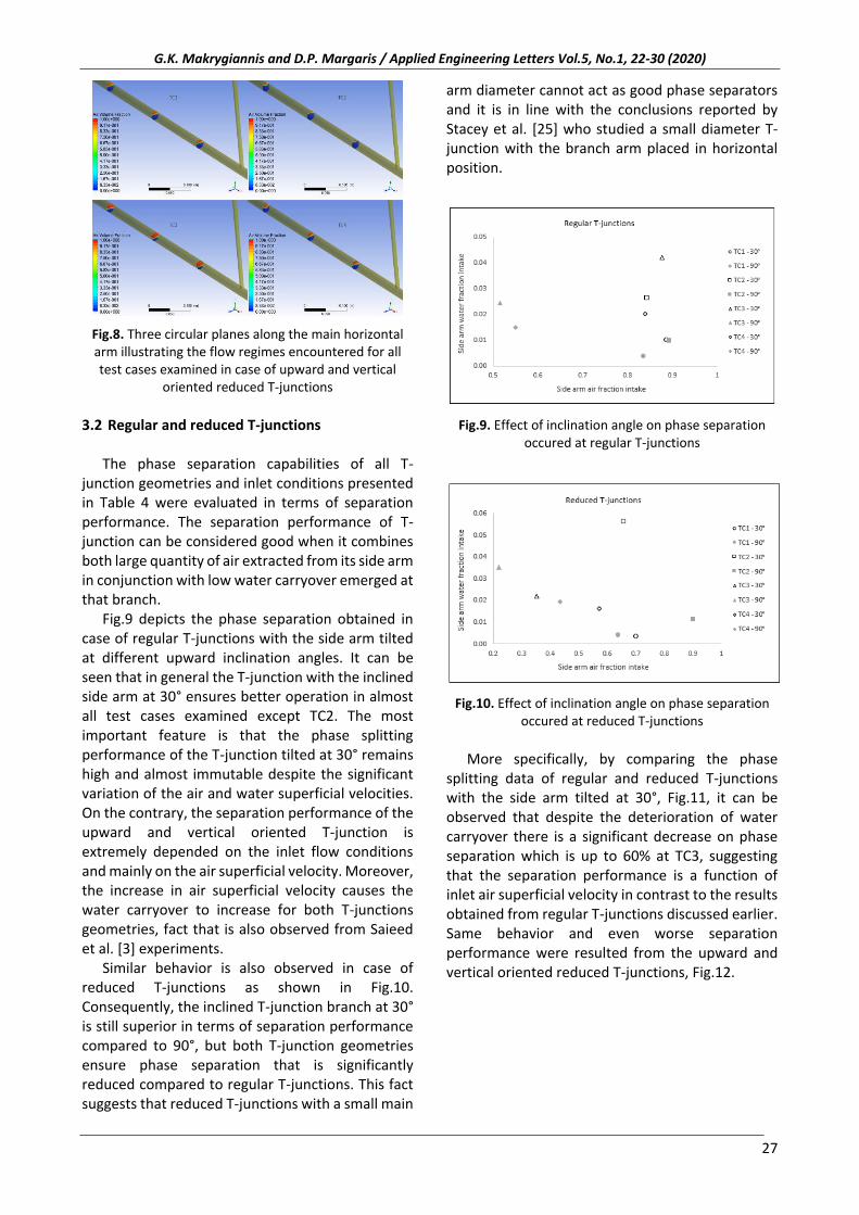
Similar behavior is also observed in case of reduced T-junctions as shown in Fig.10. Consequently, the inclined T-junction branch at 30° is still superior in terms of separation performance compared to 90°, but both T-junction geometries ensure phase separation that is significantly reduced compared to regular T-junctions. This fact suggests that reduced T-junctions with a small main
arm diameter cannot act as good phase separators and it is in line with the conclusions reported by Stacey et al. [25] who studied a small diameter T-junction with the branch arm placed in horizontal position.
Fig.9. Effect of inclination angle on phase separation occured at regular T-junctions
Fig.10. Effect of inclination angle on phase separation occured at reduced T-junctions
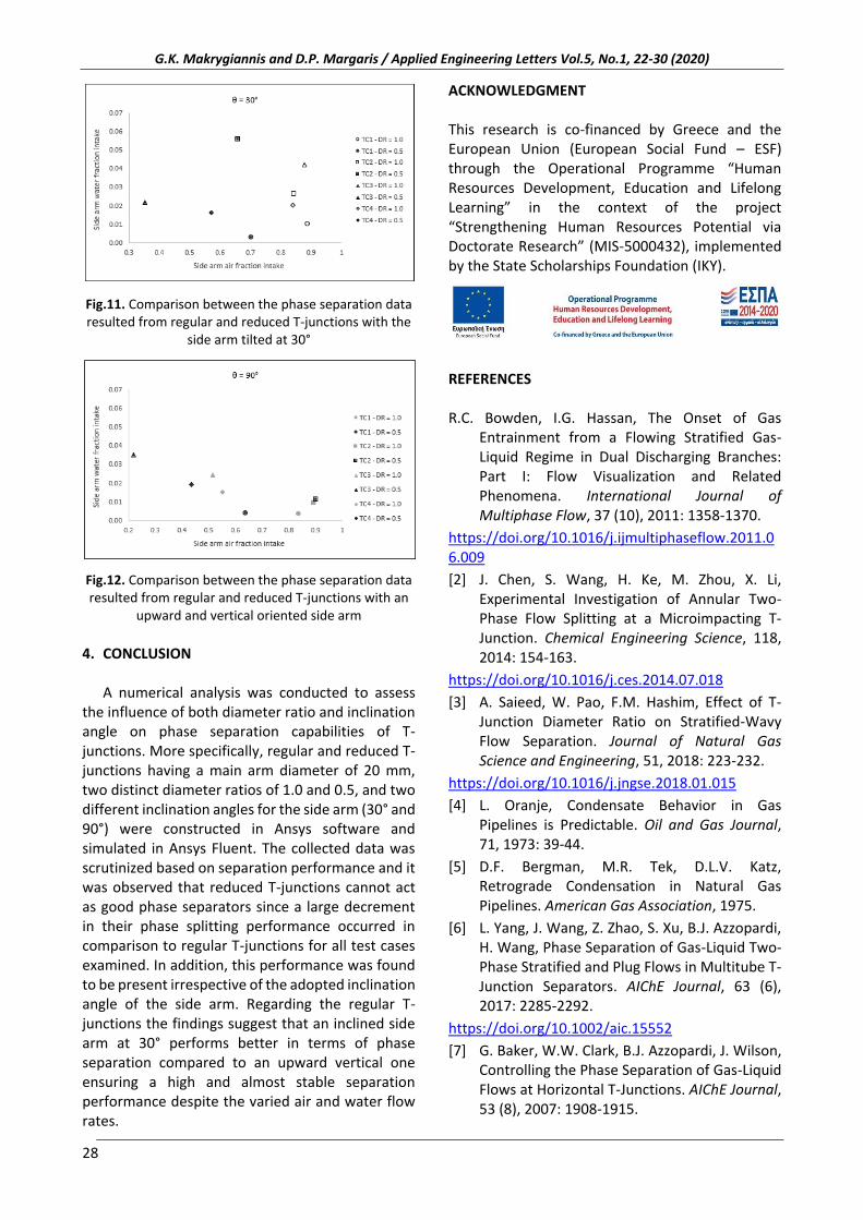
More specifically, by comparing the phase
splitting data of regular and reduced T-junctions with the side arm tilted at 30°, Fig.11, it can be observed that despite the deterioration of water carryover there is a significant decrease on phase separation which is up to 60% at TC3, suggesting that the separation performance is a function of inlet air superficial velocity in contrast to the results obtained from regular T-junctions discussed earlier. Same behavior and even worse separation performance were resulted from the upward and vertical oriented reduced T-junctions, Fig.12.
G.K. Makrygiannis and D.P. Margaris / Applied Engineering Letters Vol.5, No.1, 22-30 (2020)
28
Fig.11. Comparison between the phase separation data resulted from regular and reduced T-junctions with the
side arm tilted at 30°
Fig.12. Comparison between the phase separation data resulted from regular and reduced T-junctions with an
upward and vertical oriented side arm
4. CONCLUSION
A numerical analysis was conducted to assess
the influence of both diameter ratio and inclination angle on phase separation capabilities of T-junctions. More specifically, regular and reduced T-junctions having a main arm diameter of 20 mm, two distinct diameter ratios of 1.0 and 0.5, and two different inclination angles for the side arm (30° and 90°) were constructed in Ansys software and simulated in Ansys Fluent. The collected data was scrutinized based on separation performance and it was observed that reduced T-junctions cannot act as good phase separators since a large decrement in their phase splitting performance occurred in comparison to regular T-junctions for all test cases examined. In addition, this performance was found to be present irrespective of the adopted inclination angle of the side arm. Regarding the regular T-junctions the findings suggest that an inclined side arm at 30° performs better in terms of phase separation compared to an upward vertical one ensuring a high and almost stable separation performance despite the varied air and water flow rates.
ACKNOWLEDGMENT This research is co-financed by Greece and the European Union (European Social Fund – ESF) through the Operational Programme “Human Resources Development, Education and Lifelong Learning” in the context of the project “Strengthening Human Resources Potential via Doctorate Research” (MIS-5000432), implemented by the State Scholarships Foundation (ΙΚΥ).
REFERENCES R.C. Bowden, I.G. Hassan, The Onset of Gas
Entrainment from a Flowing Stratified Gas-Liquid Regime in Dual Discharging Branches: Part I: Flow Visualization and Related Phenomena. International Journal of Multiphase Flow, 37 (10), 2011: 1358-1370.
https://doi.org/10.1016/j.ijmultiphaseflow.2011.06.009
[2] J. Chen, S. Wang, H. Ke, M. Zhou, X. Li, Experimental Investigation of Annular Two-Phase Flow Splitting at a Microimpacting T-Junction. Chemical Engineering Science, 118, 2014: 154-163.
https://doi.org/10.1016/j.ces.2014.07.018
[3] A. Saieed, W. Pao, F.M. Hashim, Effect of T-Junction Diameter Ratio on Stratified-Wavy Flow Separation. Journal of Natural Gas Science and Engineering, 51, 2018: 223-232.
https://doi.org/10.1016/j.jngse.2018.01.015
[4] L. Oranje, Condensate Behavior in Gas Pipelines is Predictable. Oil and Gas Journal, 71, 1973: 39-44.
[5] D.F. Bergman, M.R. Tek, D.L.V. Katz, Retrograde Condensation in Natural Gas Pipelines. American Gas Association, 1975.
[6] L. Yang, J. Wang, Z. Zhao, S. Xu, B.J. Azzopardi, H. Wang, Phase Separation of Gas-Liquid Two-Phase Stratified and Plug Flows in Multitube T-Junction Separators. AIChE Journal, 63 (6), 2017: 2285-2292.
https://doi.org/10.1002/aic.15552
[7] G. Baker, W.W. Clark, B.J. Azzopardi, J. Wilson, Controlling the Phase Separation of Gas-Liquid Flows at Horizontal T-Junctions. AIChE Journal, 53 (8), 2007: 1908-1915.

G.K. Makrygiannis and D.P. Margaris / Applied Engineering Letters Vol.5, No.1, 22-30 (2020)
29
https://doi.org/10.1002/aic.11223
[8] K. Hong, Two-Phase Flow Splitting at a Pipe Tee. Journal of Petroleum Technology, 30 (2), 1978: 290-296.
https://doi.org/10.2118/6530-PA
[9] S. Rea, B.J. Azzopardi, The Split of Horizontal Stratified Flow at a Large Diameter T-Junction. AIChE Journal, 79 (4), 2001: 470-476.
https://doi.org/10.1205/026387601750282409
[10] K. Zetzmann, Phasenseparation und Druckabfall in zweiphasig durchströmten vertikalen Rohrabzweigungen (Ph.D. Thesis). University of Hannover, Hannover, 1982.
[11] S. Marti, O. Shoham, A Unified Model for Stratified-Wavy Two-Phase Flow Splitting at a Reduced T-Junction with an Inclined Branch Arm. International Journal of Multiphase Flow, 23 (4), 1997: 725-748.
https://doi.org/10.1016/S0301-9322(97)82477-9
[12] B.J. Azzopardi, The Effect of the Side Arm Diameter on the Two-Phase Flow Split at a T-Junction. International Journal of Multiphase Flow, 10 (4), 1984: 509-512.
https://doi.org/10.1016/0301-9322(84)90059-4
[13] A. Saieed, B. Sam, W. Pao, F.M. Hashim, Numerical Investigation of Side Arm Gas Volume Fraction in Two Phase T-Junction. Journal of Mechanical Engineering and Sciences, 10 (3), 2016: 2311-2323.
https://doi.org/10.15282/jmes.10.3.2016.9.0215
[14] L. Yang, B.J. Azzopardi, Phase Split of Liquid-Liquid Two-Phase Flow at a Horizontal T-Junction. International Journal of Multiphase Flow, 33 (2), 2007: 207-216.
https://doi.org/10.1016/j.ijmultiphaseflow.2006.08.004
[15] O. Shoham, S. Arirachakaran, J.P. Brill, Two-Phase Flow Splitting in a Horizontal Reduced Pipe Tee. Chemical Engineering Science, 44 (10), 1989: 2388-2391.
https://doi.org/10.1016/0009-2509(89)85174-7
[16] B.J. Azzopardi, The Effect of Side Arm Diameter on Phase Split at T-Junctions, SPE Annual Technical Conference and Exhibition, 3-6 October, 1999, Houston, Texas.
[17] E.M.K. Wren, Geometric Effects on Phase Split at a Large Diameter T-Junction (Ph.D. Thesis). University of Nottingham, Nottingham, 2001.
[18] E. Wren, B.J. Azzopardi, Affecting the Phase Split at a Large Diameter T-Junction by Using
Baffles. Experimental Thermal and Fluid Science, 28 (8), 2004: 835-841.
https://doi.org/10.1016/j.expthermflusci.2003.12.017
[19] S. Griston, J.H. Choi, Two-Phase Flow Splitting at Side-Branching Tees, SPE Western Regional Meeting, 10-13 May, 1998, Bakersfield, California.
[20] L. Walters, H. Soliman, G. Sims, Two-Phase Pressure Drop and Phase Distribution at Reduced Tee Junctions. International Journal of Multiphase Flow, 24 (5), 1998: 775-792.
[21] W. Seeger, J. Reimann, U. Müller, Two-Phase Flow in a T-Junction with a Horizontal Inlet. Part I: Phase Separation, International Journal of Multiphase Flow, 12 (4), 1986: 575-585.
https://doi.org/10.1016/0301-9322(86)90061-3
[22] V.R. Penmatcha, Two-Phase Flow Splitting at a Tee Junction with a Downward Inclined Branch Arm (M.Sc. Thesis). The University of Tulsa, Tulsa, 1993.
[23] P.J. Ashton, Two-Phase Flow Splitting at a Tee Junction with an Upward Inclined Branch Arm (M.Sc. Thesis). The University of Tulsa, Tulsa, 1993.
[24] V.R. Penmatcha, P.J. Ashton, O. Shoham, Two-Phase Stratified Flow Splitting at a T-Junction. International Journal of Multiphase Flow, 22 (6), 1996: 1105-1122.
https://doi.org/10.1016/0301-9322(96)00033-X
[25] T. Stacey, B.J. Azzopardi, G. Conte, The Split of Annular Two-Phase Flow at a Small Diameter T-Junction. International Journal of Multiphase Flow, 26 (5), 2000: 845-856.
https://doi.org/10.1016/S0301-9322(99)00051-8
[26] G.K. Makrygiannis, D.P. Margaris, Two- and Three-Dimensional Computational Investigation of the Separation Efficiency of an Air-Water Mixture Flowing Through an Inclined T-Junction Branch, 8th International Conference on Experiments/Process/System Modeling/Simulation/Optimization (8th IC-EPSMSO), 3-6 July, 2019, Athens, Greece.
[27] M. Gourma, P.G. Verdin, Two-Phase Slug Flows in Helical Pipes: Slug Frequency Alterations and Helicity Fluctuations. International Journal of Multiphase Flow, 86, 2016: 10-20.
https://doi.org/10.1016/j.ijmultiphaseflow.2016.07.013
[28] L. Xing, H. Yeung, J. Shen, Y. Cao, Numerical Study on Mitigating Severe Slugging in Pipeline/Riser System with Wavy Pipe.

G.K. Makrygiannis and D.P. Margaris / Applied Engineering Letters Vol.5, No.1, 22-30 (2020)
30
International Journal of Multiphase Flow, 53, 2013: 1-10.
https://doi.org/10.1016/j.ijmultiphaseflow.2013.01.003
[29] J. Jaeger, C.M. Santos, L.M. Rosa, H.F. Meier, D. Noriler, Experimental and Numerical Evaluation of Slugs in a Vertical Air-Water Flow. International Journal of Multiphase Flow, 101, 2018: 152-166.
https://doi.org/10.1016/j.ijmultiphaseflow.2018.01.009
[30] Y. Liu, W.Z. Li, Numerical Simulation on Two-Phase Bubbly Flow Split in a Branching T-Junction. International Journal of Air-Conditioning and Refrigeration, 19 (4), 2011: 253-262.
https://doi.org/10.1142/S2010132511000612
[31] Y. Taitel, A.E. Dukler, A Model for Predicting Flow Regime Transitions in Horizontal and Near Horizontal Gas-Liquid Flow. AIChE Journal, 22 (1), 1976.
https://doi.org/10.1002/aic.690220105
This work is licensed under a Creative Commons Attribution-Non Commercial 4.0 International License (CC BY-NC 4.0)