diagonal tension field inclination angle in steel plate ...bruneau/asce 2017 fu wang bruneau.pdf ·...
TRANSCRIPT
Diagonal Tension Field Inclination Angle inSteel Plate Shear Walls
Yushan Fu1; Fangbo Wang2; and Michel Bruneau, F.ASCE3
Abstract: Research was conducted to investigate how the inclination angle of the diagonal tension field action varies in steel plate shearwalls (SPSWs) and to determine what optimum constant angle best matches the demands obtained from finite-element (FE) analysis. AnFE model was first calibrated against experimental results that surveyed inclination angles across the web plate of an idealized SPSW as afunction of drift and that showed significant differences in inclination angles at different locations across the web plate. Then, four realSPSWs with varying aspect ratios and numbers of stories were designed and modeled for FE analyses. The variations in angle in the webplate and along the boundary elements were documented as a function of drift and showed significant variations. Combined moment–axialforce demand ratios in the SPSW boundary elements were calculated and compared for all real SPSWs to determine the preferable value ofsingle angle that could be used in design. Overall, using 45° was found to be a reasonable compromise for both horizontal and verticalboundary element (HBE and VBE, respectively) design if a single constant angle is desired. Furthermore, the demand on the web plateis not sensitive to the variation of inclination angle. Consequently, the single angle of 45° is recommended for the design of the entire SPSW.DOI: 10.1061/(ASCE)ST.1943-541X.0001779. © 2017 American Society of Civil Engineers.
Author keywords: Steel; Plate; Shear; Wall; Inclination angle; Tension; Field; LS-DYNA; Seismic effects.
Introduction
A typical steel plate shear wall (SPSW) consists of horizontal boun-dary elements (HBEs), vertical boundary elements (VBEs), andweb plates. The ultimate strength of SPSWs is reached when theweb yield in diagonal tension-field action at an angle α from thevertical and HBEs develop plastic hinging at their ends. Capacitydesign of a SPSW requires the web plate to have sufficient strengthto resist the specified story shear, and the HBE and VBE to be ableto resist the diagonal forces applied by the web plate on those boun-dary elements. Therefore, the inclination angle, denoted as α, is akey parameter in SPSW design. AISC 341-10 (AISC 2010) pro-vides an equation to calculate the inclination angle [based on re-search by Timler and Kulak (1983)]. Although this approach isgenerally accepted in design practice, this angle αwas derived froman elastic strain energy principle, whereas seismic design usuallyexpects structures to develop plastic behavior. Alternatively, forsimplicity, AISC 341-10 also allows using a constant angle of40° based on work by Dastfan and Driver (2008).
Researchers have observed from experimental or numerical re-sults that the inclination angle typically varies between 38° and 45°for well-designed SPSWs. The quasi-static experiment conductedby Timler and Kulak (1983) showed that the angle of inclination
along the vertical centerline of the web plate varied from 44° to 56°.Elgaaly et al. (1993) performed finite-element analysis using shellelements and reported that the principal tension stress direction inthe central area of the plate panel varied between 40° and 50°. InDriver et al. (1997), the principal stress directions derived from thestrain rosette data near the top right corner of a web plate variedfrom 38° to 64°, compared with the finite-element results varyingfrom 35° to 65°. Lubell (1997) plotted the principal tension strainsalong the boundary elements and the center of the panel plate atangles of inclination from the vertical, most of which were in therange of 35–40°. In Rezai’s (1999) shake table test of a steel plateshear wall with thin unstiffened webs, strain rosette results showedthat the angle of principal strain varied from 35° to 40° near thebase, and from 37° to 42° at the center of the panel. Kharrazi (2005)measured the angle of tension field at the crest of the buckle wavefrom a test, which ranged from 37° to 39°, and compared those tothe in-plane principal stress vectors obtained from FE analyses,which were in a similar range of 34°–40°. Choi et al. (2009) usedABAQUS to perform a parametric study of the inclination angleunder different aspect ratios, infill plate thicknesses, and endplatethicknesses, which showed that the average inclination angle of thetension field in the yielded web varied from 24° to 45°. More re-cently, Webster et al. (2014) conducted experimental investigationsand finite-element analyses studying how the inclination anglechanges as a function of drift. In particular, two specimens with pinconnection and slender VBE were tested, and the experimental re-sults agreed well with results from FE analysis (conducted withABAQUS). The inclination angles, both calculated by averagingvalues over the whole web and by measuring the orientation of thebuckled corrugations, were different from the value predicted byAISC (2010). Because the average inclination angle of single pan-els fixed within an elastic boundary frame at the typical design seis-mic drifts varied between 43° and 45°, and because a constant angleof 45° was believed to be simpler to implement, Webster et al.(2014) recommended using a constant angle of 45° for both capac-ity design procedure and cyclic analysis of the SPSW system. How-ever, the specimens considered by Webster had essentially rigid
1Graduate Research Assistant, Dept. of Civil, Structural and Environ-mental Engineering, Univ. at Buffalo, Amherst, NY 14260 (correspondingauthor). ORCID: http://orcid.org/0000-0003-3258-3389. E-mail: [email protected]
2Graduate Research Assistant, Dept. of Civil, Structural and Environ-mental Engineering, Univ. at Buffalo, Amherst, NY 14260. E-mail:[email protected]
3Professor, Dept. of Civil, Structural and Environmental Engineering,Univ. at Buffalo, Amherst, NY 14260. E-mail: [email protected]
Note. This manuscript was submitted on July 8, 2016; approved onDecember 15, 2016; published online on March 15, 2017. Discussion per-iod open until August 15, 2017; separate discussions must be submittedfor individual papers. This paper is part of the Journal of StructuralEngineering, © ASCE, ISSN 0733-9445.
© ASCE 04017058-1 J. Struct. Eng.
J. Struct. Eng., 2017, 143(7): -1--1
HBEs, slender VBEs, and pure pin connections between the boun-dary frame members, for the sake of experimental purposes, whichmade them different from real SPSWs. Although consideration of asingle angle of 45° is appealing for design purposes, it is unknownwhether the findings reported by Webster et al. (2014) would re-main true for real SPSWs with realistic boundary elements, differ-ent aspect ratios, and different numbers of stories. Such informationis required to overcome possible (and arguably, founded) reserva-tions from code committee members against changing the designrequirements for SPSWs. Furthermore, because the forces inducedto the HBEs and VBEs by the yielding web are directly relatedto the inclination angle developed near the boundary elements, ad-ditional detailed information of the angle along such boundaryelement, and information on how these demands compare to thoseobtained using a constant inclination angle, is also required.
The work reported in this study was conducted to expend on priorknowledge and provide the additional evidence needed to determinewhat should be the optimum inclination angle of the tension fieldaction to consider for the design of SPSWs. Furthermore, in the pro-cess of investigating how the inclination angle of the diagonal ten-sion field action varies in different locations of SPSWs, particularattention was paid to determine the demands from these angleson the boundary elements and the effect and impact of these angleson the design of both the web and the boundary elements (HBEs andVBEs). Finally, based on all these results for all components of theSPSWs, the objective of this research was to determine what the op-timum constant angle to use for the design of SPSWs best matchesthe demands obtained from finite-element analysis. In simpler terms,the research investigated how the inclination angle of the tensionfield action changes in real SPSWs having different aspect ratiosand numbers of stories, at various drifts through nonlinear inelasticresponse for SPSWs designed in compliance with AISC (2010), andhow this change impacts design. Ultimately, the objective was to de-termine whether the constant inclination angle of 40° provided in theAISC Seismic Specifications should continue to be used, or whetherit should be replaced by a different value, such as the 45° value rec-ommended by Webster et al. (2014) or any other value.
The investigation was conducted using the LS-DYNA finite-element software to model SPSWs. The LS-DYNA model was firstcalibrated by replicating the experimental and ABAQUS analysis re-sults obtained by Webster et al. (2014) for simple tested specimenshaving pin HBE-to-VBE connections and cutouts at the web platecorners. Then, this validated LS-DYNA finite-element model wasused to further investigate the changes in inclination angle and theirimpact on SPSW behavior for modified versions of Webster’s speci-men, first without cutouts at the corner of the webs, and then withrigid HBE-to-VBE connections (still without the web cutouts).
Then, two real single-story SPSWs and two real 3-story SPSWswere subsequently designed, with panel aspect ratios of 1 and 2.Corresponding LS-DYNA models were built also modeling theHBEs and VBEs. The plastic behavior of HBE was captured byconsidering development of the plastic hinge at the end of theHBEs. This was done to observe how the inclination angle variedas a function of number of stories and panel aspect ratios forSPSWs designed per AISC (2010). To determine what appropriateor optimum constant angle should be used for SPSW design, de-mands from actual results obtained from finite-element analysis,and demands calculated using various assumed constant inclinationangles, were compared for all cases of SPSWs aspect ratio andnumber of stories considered. For HBEs and VBEs, these wereexpressed by calculating combined moment–axial force demandratios. In this paper, the terms HBE and beam, as well as VBE andcolumn, are used interchangeably, because both terms are com-monly used in the literature.
Model Calibration
Dimensions and Boundary Conditions
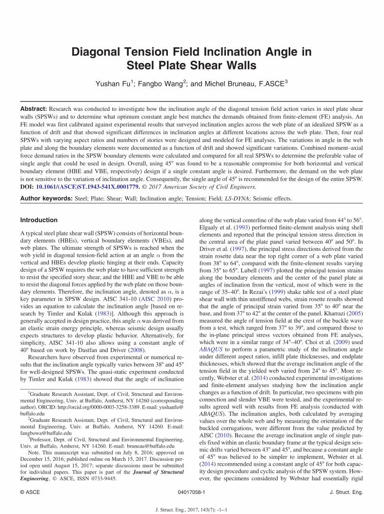
In the LS-DYNA model developed to replicate Specimen 2-22 inWebster et al. (2014), dimension of the steel web plate is 762 ×762 × 0.71 mm (length × height × thickness). Width of the cutoutin each corner of the web plate is 140 mm. The VBE is a 25.4 ×63.5 mm rectangular section. The HBE is a 71 × 150 mm rectan-gular section, made equivalent to the W6 × 25 section used inWebster et al. (2014) by having the same depth and moment ofinertia. Connection between the VBE and HBE in the Webster et al.(2014) specimen was achieved by using an actual pin, and a pointconnection was implemented in the LS-DYNA model to achieve thesame behavior. The bottom beam was continuously fixed alongthe wall’s base. To account for initial imperfections, the nodesin the web plate were initially perturbed using a harmonic field withan amplitude of t=2 ¼ 0.035 mm in the z-direction (i.e., perpen-dicular to the plate) and a wavelength of 1524 mm in both x- andy-directions.
Material and Element
The constitutive model chosen for the steel web plate was anelastic-plastic model without strain rate effect. (i.e., materialMAT024_PIECEWISE_LINEAR_PLASTICITY in LS-DYNA).The material was specified in this study as having a Young’s modu-lus of 151,000 MPa, a yielding strength of 287 MPa, a Poisson ratioof 0.30, and a density of 7,850 kg=m3. Because they were re-ported to remain elastic in the Webster et al. (2014) study, beamsand columns were modeled as an elastic material (i.e., usingLS-DYNA’s material MAT001_ELASTIC), with a Young’s modu-lus of 205,000 MPa and a Poisson ratio of 0.30 [all aforementionednumerical values were taken as those reported by Webster et al.(2014)]. To model the actual pin joint of the beam-column connec-tion, beam and column elements in the overlapping area were mod-eled with separate and independent finite-element meshes usingrigid material (i.e., using LS-DYNA’s material MAT020_RIGIDand a Young’s modulus 205,000 MPa); hence, they did not sharenodes in the same location. The option JOINT_SPHERICAL inLS-DYNA was used at the two center nodes (from the beam andcolumn, respectively) in the overlapping area. The SPHERICALJOINT option in LS-DYNA allows six degrees of freedoms. Onlythe out-of-plane degree of freedom (i.e., z-translation) was con-strained on the peripheral nodes of the overlapping area as shownin Fig. 1. Belytschko-Tsay shell elements were used for the webplate, VBEs and HBEs because of their computational efficiency.The number of through thickness integration points was set to 9,to be the same as in Webster (2013).
Loading Protocol
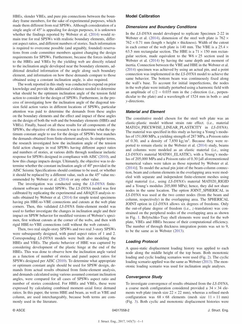
A quasi-static displacement loading history was applied to eachnode along the middle height of the top beam. Both monotonicloading and cyclic loading scenarios were used (Fig. 2). The cyclicloading scenario applied was the same as Webster (2013). The mon-otonic loading scenario was used for inclination angle analyses.
Convergence Study
To investigate convergence of results obtained from the LS-DYNA,a coarse mesh configuration considered provided a 34 × 34 ele-ments web plate (mesh size 22 × 22 mm), whereas a refined meshconfiguration was 68 × 68 elements (mesh size 11 × 11 mm)(Fig. 3). Both cyclic and monotonic displacement histories were
© ASCE 04017058-2 J. Struct. Eng.
J. Struct. Eng., 2017, 143(7): -1--1
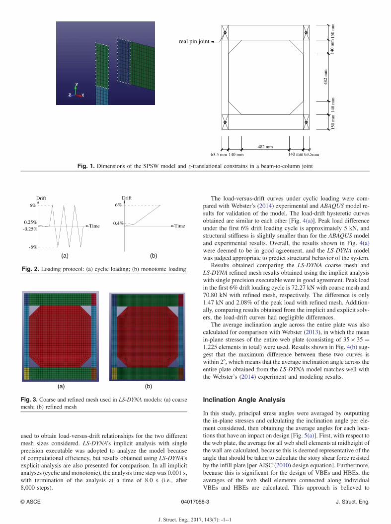
used to obtain load-versus-drift relationships for the two differentmesh sizes considered. LS-DYNA’s implicit analysis with singleprecision executable was adopted to analyze the model becauseof computational efficiency, but results obtained using LS-DYNA’sexplicit analysis are also presented for comparison. In all implicitanalyses (cyclic and monotonic), the analysis time step was 0.001 s,with termination of the analysis at a time of 8.0 s (i.e., after8,000 steps).
The load-versus-drift curves under cyclic loading were com-pared with Webster’s (2014) experimental and ABAQUS model re-sults for validation of the model. The load-drift hysteretic curvesobtained are similar to each other [Fig. 4(a)]. Peak load differenceunder the first 6% drift loading cycle is approximately 5 kN, andstructural stiffness is slightly smaller than for the ABAQUS modeland experimental results. Overall, the results shown in Fig. 4(a)were deemed to be in good agreement, and the LS-DYNA modelwas judged appropriate to predict structural behavior of the system.
Results obtained comparing the LS-DYNA coarse mesh andLS-DYNA refined mesh results obtained using the implicit analysiswith single precision executable were in good agreement. Peak loadin the first 6% drift loading cycle is 72.27 kN with coarse mesh and70.80 kN with refined mesh, respectively. The difference is only1.47 kN and 2.08% of the peak load with refined mesh. Addition-ally, comparing results obtained from the implicit and explicit solv-ers, the load-drift curves had negligible differences.
The average inclination angle across the entire plate was alsocalculated for comparison with Webster (2013), in which the meanin-plane stresses of the entire web plate (consisting of 35 × 35 ¼1,225 elements in total) were used. Results shown in Fig. 4(b) sug-gest that the maximum difference between these two curves iswithin 2°, which means that the average inclination angle across theentire plate obtained from the LS-DYNA model matches well withthe Webster’s (2014) experiment and modeling results.
Inclination Angle Analysis
In this study, principal stress angles were averaged by outputtingthe in-plane stresses and calculating the inclination angle per ele-ment considered, then obtaining the average angles for each loca-tions that have an impact on design [Fig. 5(a)]. First, with respect tothe web plate, the average for all web shell elements at midheight ofthe wall are calculated, because this is deemed representative of theangle that should be taken to calculate the story shear force resistedby the infill plate [per AISC (2010) design equation]. Furthermore,because this is significant for the design of VBEs and HBEs, theaverages of the web shell elements connected along individualVBEs and HBEs are calculated. This approach is believed to
63.5 mm 63.5mm
150
mm
150
mm
140 mm
482 mm
140 mm
140
mm
482
mm
140
mmreal pin joint
Fig. 1. Dimensions of the SPSW model and z-translational constrains in a beam-to-column joint
6%
-6%
0.25%-0.25%
Drift
Time
6%
Drift
Time0.4%
(a) (b)
Fig. 2. Loading protocol: (a) cyclic loading; (b) monotonic loading
(a) (b)
Fig. 3. Coarse and refined mesh used in LS-DYNA models: (a) coarsemesh; (b) refined mesh
© ASCE 04017058-3 J. Struct. Eng.
J. Struct. Eng., 2017, 143(7): -1--1

provide a better understanding on the design consequence of vary-ing inclination angles.
Fig. 5(b) shows the inclination angle versus drift relationship ofthe web plate shell elements located along the top beam, bottombeam, left column, right column, and middle web, identified by thelines in Fig. 5(a). The angles presented in Fig. 5(b) are the averagesfor all the elements along each line considered.
In Fig. 5(b), all the curves exhibit a similar trend, in that theangle initially decreases from a relatively high initial value at lowdrift (and thus low stresses), up to nearly 0.5% drift (at which someparts of the infill approach their elastic limit), and then progres-sively increase afterward up to the maximum drift considered. Inthe earlier stages of elastic response, stresses applied by the steelplate to the boundary elements are not of design concern becausethe stresses are low (Fu et al. 2017). Hence, the high values of angleinitially observed from 0 to 0.5% drift have no significance onstructural design.
However, in spite of this similarity in trend observed inFig. 5(b), quite different angle values are obtained along the differ-ent locations considered. Top and bottom beams have approxi-mately the same angle values, starting as low as 33° at 0.5% driftand reaching an angle of approximately 37° beyond 3% drift. Sim-ilarly, the left and right columns have approximately the same anglevalues, starting as low as 40° for the left column and 50° for theright column at 1% drift, and reaching an angle of approximately
53° at 3% drift. In addition, the angle across the middle web is ap-proximately 37° at 1% drift, 44° at 3% drift, and 48° at 6% drift.
Effect of Cutout Corners and Beam-to-ColumnConnections
To investigate how the presented cutout corners and the type ofbeam-to-column connections affect the preceding observation thatthe inclination angle of the diagonal tension field action variesacross the web plate, two alternative models were designed with thesame material models, loading protocol, and boundary conditionsas the validated LS-DYNA model. The main differences from thevalidated LS-DYNA model were connection type and absence ofcutout. Model A is with pin HBE-to-VBE connections and withoutweb cutouts at the corner of the web plate, and Model B is withrigid HBE-to-VBE connections and also without cutouts. In addi-tion, elastoplastic behaviors of HBEs and VBEs were considered inModel B. A summary of these differences is presented in Table 1.To simulate the rigid connection of HBE and VBE, nodes at the endof the HBE were merged to the face of VBE.
Fig. 6 shows the change in inclination angle of the tension fieldaction as a function of drift for the web plate in the three modelslisted in Table 1. For Model A, the angle in each location followsa similar trend as the validated model after 2% drift. Up to the
−0.08 −0.06 −0.04 −0.02 0 0.02 0.04 0.06 0.08
−75
−50
−25
0
25
50
75
Drift (rads)
Loa
d (k
N)
0 0.02 0.04 0.06
35
40
45
α = αel
α = 45 deg
Drift (rads)
α (d
eg)
ABAQUSExperimentYield Point
ABAQUS (Webster, 2014)Experiment (Webster, 2014)Yield Point (Webster, 2014)
LS-DYNA model
LS-DYNA implicit refined meshLS-DYNA implicit coarse meshLS-DYNA explicit coarse meshABAQUS (Webster, 2014)Experiment (Webster, 2014)
(a) (b)
Fig. 4. Comparison of LS-DYNA and ABAQUS models and experimental data in Webster et al. (2014): (a) load-drift curves under cyclic loading;(b) average inclination angles over the entire web plate
0 1 2 3 4 5 6 7 820
25
30
35
40
45
50
55
60
top beam bottom beam left column right column middle web
Ang
le
Drift(rads)
Top beam
Bottom beam
Middle webLef
t col
umn
Rig
ht c
olum
n
(a) (b)
Fig. 5. Inclination angle variation: (a) location of shell element groups; (b) migration of inclination angle of the web plate
© ASCE 04017058-4 J. Struct. Eng.
J. Struct. Eng., 2017, 143(7): -1--1
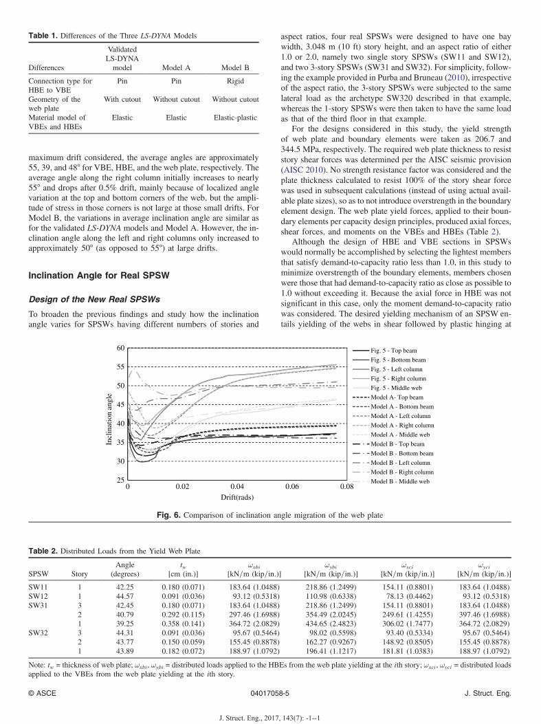
maximum drift considered, the average angles are approximately55, 39, and 48° for VBE, HBE, and the web plate, respectively. Theaverage angle along the right column initially increases to nearly55° and drops after 0.5% drift, mainly because of localized anglevariation at the top and bottom corners of the web, but the ampli-tude of stress in those corners is not large at those small drifts. ForModel B, the variations in average inclination angle are similar asfor the validated LS-DYNA models and Model A. However, the in-clination angle along the left and right columns only increased toapproximately 50° (as opposed to 55°) at large drifts.
Inclination Angle for Real SPSW
Design of the New Real SPSWs
To broaden the previous findings and study how the inclinationangle varies for SPSWs having different numbers of stories and
aspect ratios, four real SPSWs were designed to have one baywidth, 3.048 m (10 ft) story height, and an aspect ratio of either1.0 or 2.0, namely two single story SPSWs (SW11 and SW12),and two 3-story SPSWs (SW31 and SW32). For simplicity, follow-ing the example provided in Purba and Bruneau (2010), irrespectiveof the aspect ratio, the 3-story SPSWs were subjected to the samelateral load as the archetype SW320 described in that example,whereas the 1-story SPSWs were then taken to have the same loadas that of the third floor in that example.
For the designs considered in this study, the yield strengthof web plate and boundary elements were taken as 206.7 and344.5 MPa, respectively. The required web plate thickness to resiststory shear forces was determined per the AISC seismic provision(AISC 2010). No strength resistance factor was considered and theplate thickness calculated to resist 100% of the story shear forcewas used in subsequent calculations (instead of using actual avail-able plate sizes), so as to not introduce overstrength in the boundaryelement design. The web plate yield forces, applied to their boun-dary elements per capacity design principles, produced axial forces,shear forces, and moments on the VBEs and HBEs (Table 2).
Although the design of HBE and VBE sections in SPSWswould normally be accomplished by selecting the lightest membersthat satisfy demand-to-capacity ratio less than 1.0, in this study tominimize overstrength of the boundary elements, members chosenwere those that had demand-to-capacity ratio as close as possible to1.0 without exceeding it. Because the axial force in HBE was notsignificant in this case, only the moment demand-to-capacity ratiowas considered. The desired yielding mechanism of an SPSW en-tails yielding of the webs in shear followed by plastic hinging at
25
30
35
40
45
50
55
60
0 0.02 0.04 0.06 0.08
Incl
inat
ion
angl
e
Drift(rads)
Fig. 5 - Top beam
Fig. 5 - Bottom beam
Fig. 5 - Left column
Fig. 5 - Right column
Fig. 5 - Middle web
Model A- Top beam
Model A - Bottom beam
Model A - Left column
Model A - Right column
Model A - Middle web
Model B - Top beam
Model B - Bottom beam
Model B - Left column
Model B - Right column
Model B - Middle web
Fig. 6. Comparison of inclination angle migration of the web plate
Table 2. Distributed Loads from the Yield Web Plate
SPSW StoryAngle
(degrees)tw
[cm (in.)]ωxbi
[kN=m (kip=in:)]ωybi
[kN=m (kip=in:)]ωxci
[kN=m (kip=in:)]ωyci
[kN=m (kip=in:)]
SW11 1 42.25 0.180 (0.071) 183.64 (1.0488) 218.86 (1.2499) 154.11 (0.8801) 183.64 (1.0488)SW12 1 44.57 0.091 (0.036) 93.12 (0.5318) 110.98 (0.6338) 78.13 (0.4462) 93.12 (0.5318)SW31 3 42.45 0.180 (0.071) 183.64 (1.0488) 218.86 (1.2499) 154.11 (0.8801) 183.64 (1.0488)
2 40.79 0.292 (0.115) 297.46 (1.6988) 354.49 (2.0245) 249.61 (1.4255) 397.46 (1.6988)1 39.25 0.358 (0.141) 364.72 (2.0829) 434.65 (2.4823) 306.02 (1.7477) 364.72 (2.0829)
SW32 3 44.31 0.091 (0.036) 95.67 (0.5464) 98.02 (0.5598) 93.40 (0.5334) 95.67 (0.5464)2 43.77 0.150 (0.059) 155.45 (0.8878) 162.27 (0.9267) 148.92 (0.8505) 155.45 (0.8878)1 43.89 0.182 (0.072) 188.97 (1.0792) 196.41 (1.1217) 181.81 (1.0383) 188.97 (1.0792)
Note: tw = thickness of web plate; ωxbi, ωybi = distributed loads applied to the HBEs from the web plate yielding at the ith story; ωxci, ωyci = distributed loadsapplied to the VBEs from the web plate yielding at the ith story.
Table 1. Differences of the Three LS-DYNA Models
Differences
ValidatedLS-DYNA
model Model A Model B
Connection type forHBE to VBE
Pin Pin Rigid
Geometry of theweb plate
With cutout Without cutout Without cutout
Material model ofVBEs and HBEs
Elastic Elastic Elastic-plastic
© ASCE 04017058-5 J. Struct. Eng.
J. Struct. Eng., 2017, 143(7): -1--1

the ends of the HBEs, and the resulted designs in this study areexpected to similarly behave when pushed over. The resulting de-signed SPSWs are presented in Fig. 7.
LS-DYNA Modeling of Four Real SPSWs
New LS-DYNA models were built for the four real SPSWs.Different from the validated model, the new models had three-dimensional boundary elements, which is more representative ofreal SPSWs. The HBEs were rigidly connected with the VBEs bymerging the nodes at the same coordinate. All panel zones weredefined as rigid body with respect to a nodal point at their masscenters. The nodal points of the two bottom panel zones were pin-supported on the ground by using the NODAL RIGID BODY andBOUNDARY_PRESCRIBED MOTION RIGID. BOUNDARY_PRESCRIBED_MOTION_RIGID was defined with a zero-valuedload curve for all translational degrees of freedom, so that thepanel zone could only rotate with respect to this point. In addition,
z-constraints (z is in the direction normal to the web plate) wereapplied to the flange plate edge nodes of the upper panel zones,to constrain the SPSW to move within x-y plane. In addition, theHBE ends, over a length equal to approximately one-sixth of thespan length, were modeled with a more refined mesh to better cap-ture the nonlinear inelastic behavior of the plastic hinges at thoselocations. The material model used for real SPSWs was obtainedfrom the coupon test in Webster et al. (2014) and converted intonormalized values (Fig. 8).
Node merging requires nodes from one part to share identicalcoordinates with those of another part. However, in this case, differ-ent flange widths of VBEs and HBEs resulted in different meshes[Fig. 9(a), arrows]. To simplify the modeling and avoid iterations ofmesh size, the actual cross sections were converted into equivalentcross sections over the 3-story SPSW models. Two principles werefollowed for that purpose: (1) for the VBEs, the equivalent sectionwas sized to have identical height, shear, and moment capacity asthe original section, to avoid the premature yielding of the web by
3048 mm
3048
mm
3048 mm
3048
mm
3048
mm
3048
mm
3048
mm
3048
mm
3048
mm
6096 mm
6096 mm
3048
mm
W12x65
W14x48
W14x38
W18x97
W12x65
W12x65
W18x76
W14x61
W12x45
W24x117
W18x86
W18x86
W18
x106
98x61W W
16x8
9
W21
x111
W21
x111
67x81W
11 1 x1 2W
8 71 x7 2W
W18
x76
W21
x111
W27
x178
W21
x122
W27
x194
W18
x106
W21
x122
W27
x194
tw=3.581 mm
(0.96)
(0.9
9)
(0.96)
(0.99)
(0.96)
(0.96)
(0.98)
(0.94)
(1.00)
(0.99)
(0.9
5)
(1.0
0)(0
.98)
(0.9
7)
(0.9
8)(0
.95)
(0.9
7)
(0.94)
tw=2.921 mm
tw=1.803 mm tw=0.914 mm
tw=1.499 mm
tw=1.829 mm
tw=0.914 mm
α=42.45°
α=40.79°
α=39.25°
α=42.25° α=44.57°
α=43.89°
α=43.77°
α=44.31°
tw=1.803 mm
(a) (b)
(c) (d)
Fig. 7. SPSW elevations: (a) SW11; (b) SW12; (c) SW31; (d) SW32
© ASCE 04017058-6 J. Struct. Eng.
J. Struct. Eng., 2017, 143(7): -1--1

shear; and (2) the flange width of HBEs was converted to align withthe mesh of VBEs, without changing their flange area.
Four real SPSWs were studied under monotonic loading. ForSW11, both force control and displacement control were done forcomparison. In the former case, a load was applied to each nodealong the middle height of the top beam; whereas for the latter, thedisplacement of the nodal point in the upper right panel zone wascontrolled. Conceptually, the displacement control analysis couldbe thought of as preventing the development of axial deformationsin the top beam and possibly constraining or affecting the strainfield in the web panel. However, comparison of stress results aswell as moment and axial force diagrams along the top HBE for thedisplacement-control and force-control analyses did not reveal asignificant difference. Both approaches gave similar results, glob-ally (load-displacement curves) and locally (magnitude and shapeof moment and axial force diagrams). Therefore, because the analy-sis using displacement control was found to achieve a better per-formance in terms of convergence, it was eventually used for all thefinite-element model final analyses.
Inclination Angle Analysis of SW11 and Deformation ofthe Top Beam
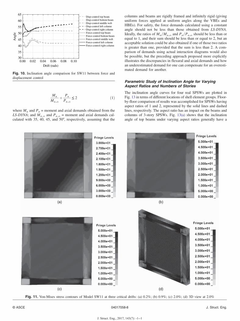
Fig. 10 shows the overall trend in the variation of the inclinationangle as a function of drift for SW11, which is quite similar to the
inclination angle curve shape of Model B observed in Fig. 6, butwith values generally higher than those of Model B. For example,for the right column, results fluctuate noticeably for drifts lowerthan 2% drift, but remain higher than 50°; at 6% drift, the inclina-tion angle reaches 56° in SW11 compared with 50° in Model B. Forweb plate and beams, the average inclination angles of SW11 reachup to approximately 52° for the web plate and 42° for the beams at6% drift, compared with the 45° for web plate and 37° for the beamsin Model B. The observed fluctuations in the beam results at lowerdrifts were deemed to result from the deflections of HBE.
To study the cause of the aforementioned fluctuations in re-sults at lower drifts, a few critical drifts for response in the resultsobtained with the LS-DYNA model were first determined and an-alyzed. In view of symmetry, only results for the top beam are dis-cussed in this study. Von Mises stress contours of Model SW11for each selected drifts are shown in Fig. 11. These drifts corre-spond to the development of web yielding and plastic hinging atthe right and left ends of the HBE, at around 0.2, 0.9, and 2%,respectively. The shear deformation was found to be non-negligiblein the HBE of real SPSWs.
In addition, the principal stress vectors along the boundary el-ements and in the web plate at 2% drift were obtained from the LS-DYNA and plotted in Fig. 12. For clarity in presenting the results,the numerical values shown along the top HBE and left VBE inFig. 12 are the calculated inclination angles for the shell elementstaken at an interval of five elements along the boundary frame. Thisillustrates that inclination angles along the boundary elements, inthis case, vary by as much as 19° along the HBE (from 30.3° to49.5°) and 8° along the VBE (from 48.3° to 56.0°).
Optimum Constant Angle for Real SPSW Design
Combined Moment–Axial Force Demand Ratio
Because the boundary elements are subjected to combined axialand flexural loading, moment–axial force interaction is consideredin their design. To compare the forces obtained from the finite-element analyses with those calculated using constant angle mod-els, it is necessary to perform that comparison considering both theeffect of axial and flexural demands. This comparison was doneusing the following relationship:
(0.74,1.00)E
ngin
eeri
ng s
tres
s
Engineering stress
(10.5,1.05)(26.3,1.18)
(86.8,1.31)
(121,1.33)
(147,1.33)
y( )/
y( )/
Fig. 8. Normalized material model used by Webster et al. (2014)
Fig. 9. Section conversion applied for 3-story SPSWs: (a) before section conversion; (b) after section conversion
© ASCE 04017058-7 J. Struct. Eng.
J. Struct. Eng., 2017, 143(7): -1--1
Mu
Mu αþ Pu
Pu α≤ 2 ð1Þ
where Mu and Pu = moment and axial demands obtained from theLS-DYNA; and Mu α and Pu α = moment and axial demands cal-culated with 35, 40, 45, and 50°, respectively, assuming that the
columns and beams are rigidly framed and infinitely rigid (givinguniform forces applied at uniform angles along the VBEs andHBEs). For safety, the force demands calculated using a constantangle should not be less than those obtained from LS-DYNA.Ideally, the ratios of Mu=Mu α and Pu=Pu α should be less than orequal to 1, and their sum should be less than or equal to 2, but anacceptable solution could be also obtained if one of those two ratiosis greater than one, provided that the sum is less than 2. A com-parison of demands using actual interaction diagrams would alsobe possible, but the preceding approach proposed more explicitlyillustrates the discrepancies in flexural and axial demands and howan underestimated demand for one can compensate for an overesti-mated demand for another.
Parametric Study of Inclination Angle for VaryingAspect Ratios and Numbers of Stories
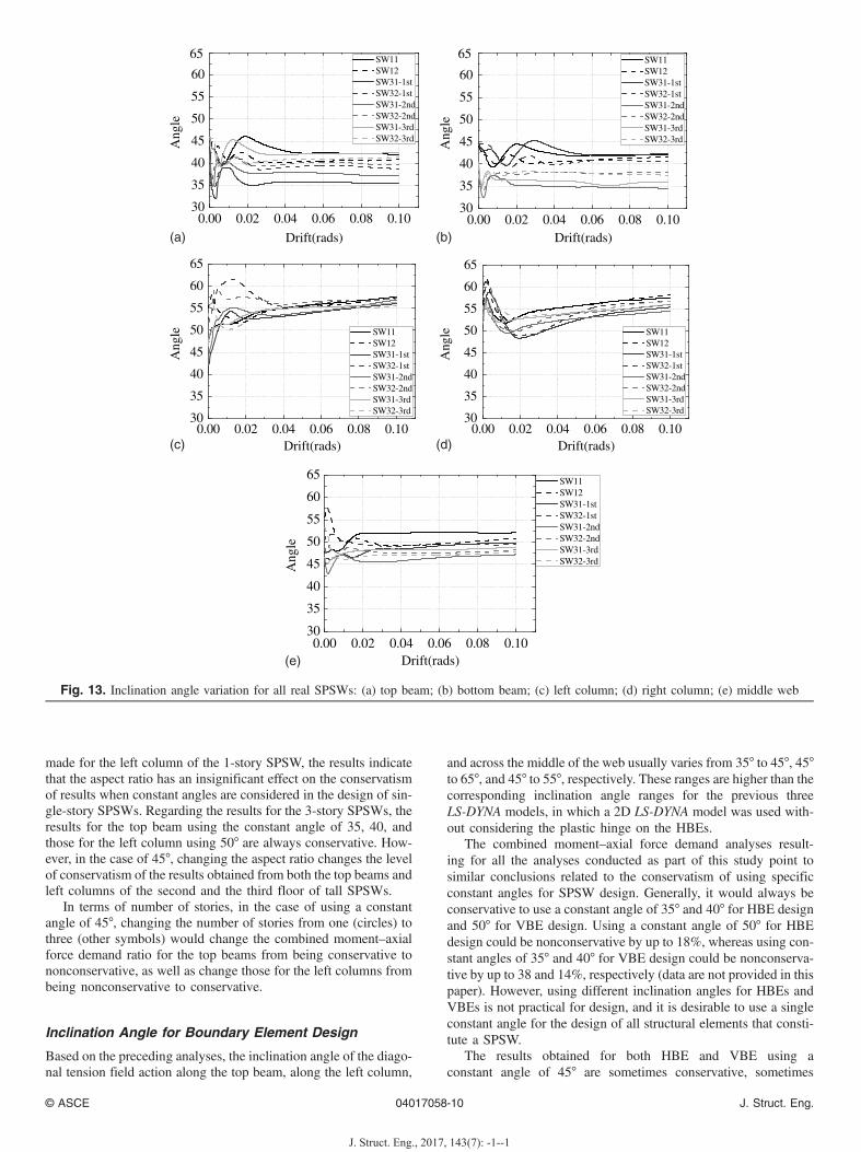
The inclination angle curves for four real SPSWs are plotted inFig. 13 in terms of different locations of shell element groups. Floor-by-floor comparison of results was accomplished for SPSWs havingaspect ratios of 1 and 2, represented by the solid lines and dashedlines, respectively. The aspect ratio has an impact on the beams andcolumns of 3-story SPSWs. Fig. 13(a) shows that the inclinationangle of top beams under varying aspect ratios generally have a
0.00 0.02 0.04 0.06 0.08 0.1030
35
40
45
50
55
60
65 Disp-control top beam Disp-control bottom beam Disp-control middle web Disp-control left column Disp-control right column Force-control top beam Force-control bottom beam Force-control middle web Force-control left column Force-control right column
Ang
le
Drift (rads)
Fig. 10. Inclination angle comparison for SW11 between force anddisplacement control
Fig. 11. Von-Mises stress contours of Model SW11 at three critical drifts: (a) 0.2%; (b) 0.9%; (c) 2.0%; (d) 3D view at 2.0%
© ASCE 04017058-8 J. Struct. Eng.
J. Struct. Eng., 2017, 143(7): -1--1

difference of approximately 4°; Fig. 13(c) shows that the greater theaspect ratio, the more serious the fluctuation in results obtained forthe left columns. Fig. 13(e) shows that the aspect ratio also has an in-fluence on the middleweb, taking 1-story SPSWs for example, with amaximum difference of 10° before 2% drift, and 3° for larger drifts.
Regarding the number of stories, the variations on inclinationangle for 1-story SPSWs were also compared with those for eachfloor of the corresponding 3-story SPSWs having identical aspectratios. Fig. 13 shows that the curves for the columns of 1-storySPSW are significantly different from those for the first floor ofthe corresponding 3-story SPSW, with up to a 10° difference. How-ever, the magnitude of the differences decreased when comparedwith the higher floor of 3-story SPSW. As for the top and bottombeams, the curves obtained from the SPSWs with an aspect ratio of
1 show that results for the 1-story SPSW do not match those on anyof the floors of the corresponding 3-story SPSW, with a maximumdifference of approximately 7° after 2% drift. For the SPSWs withan aspect ratio of 2, this difference is significantly reduced to ap-proximately 3°, and the lower floor matches better with the corre-sponding 1-story SPSW than the higher floors. Similar observationcan be made for the middle web.
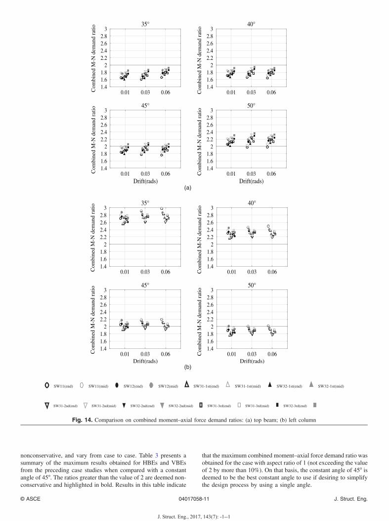
Plotted in Fig. 14 are the combined moment–axial force demandratios of each constant angle considered for the top beam and leftcolumn. In terms of aspect ratios, results obtained for the top beamof 1-story SPSWs (filled and open circles) are typically eitherconservative or nonconservative, namely, either less than 2 whenusing the constant angle from 35 to 45° or greater than 2 when usingthe constant angle of 50°. Because the same observation can be
Fig. 12. Principal stress vectors of SW11 at 2% drift and different arrow scale factors: (a) 0.1; (b) 0.5; (c) 0.2
© ASCE 04017058-9 J. Struct. Eng.
J. Struct. Eng., 2017, 143(7): -1--1
made for the left column of the 1-story SPSW, the results indicatethat the aspect ratio has an insignificant effect on the conservatismof results when constant angles are considered in the design of sin-gle-story SPSWs. Regarding the results for the 3-story SPSWs, theresults for the top beam using the constant angle of 35, 40, andthose for the left column using 50° are always conservative. How-ever, in the case of 45°, changing the aspect ratio changes the levelof conservatism of the results obtained from both the top beams andleft columns of the second and the third floor of tall SPSWs.
In terms of number of stories, in the case of using a constantangle of 45°, changing the number of stories from one (circles) tothree (other symbols) would change the combined moment–axialforce demand ratio for the top beams from being conservative tononconservative, as well as change those for the left columns frombeing nonconservative to conservative.
Inclination Angle for Boundary Element Design
Based on the preceding analyses, the inclination angle of the diago-nal tension field action along the top beam, along the left column,
and across the middle of the web usually varies from 35° to 45°, 45°to 65°, and 45° to 55°, respectively. These ranges are higher than thecorresponding inclination angle ranges for the previous threeLS-DYNA models, in which a 2D LS-DYNA model was used with-out considering the plastic hinge on the HBEs.
The combined moment–axial force demand analyses result-ing for all the analyses conducted as part of this study point tosimilar conclusions related to the conservatism of using specificconstant angles for SPSW design. Generally, it would always beconservative to use a constant angle of 35° and 40° for HBE designand 50° for VBE design. Using a constant angle of 50° for HBEdesign could be nonconservative by up to 18%, whereas using con-stant angles of 35° and 40° for VBE design could be nonconserva-tive by up to 38 and 14%, respectively (data are not provided in thispaper). However, using different inclination angles for HBEs andVBEs is not practical for design, and it is desirable to use a singleconstant angle for the design of all structural elements that consti-tute a SPSW.
The results obtained for both HBE and VBE using aconstant angle of 45° are sometimes conservative, sometimes
0.00 0.02 0.04 0.06 0.08 0.1030
35
40
45
50
55
60
65
Ang
le
Drift(rads)
SW11 SW12 SW31-1st SW32-1st SW31-2nd SW32-2nd SW31-3rd SW32-3rd
0.00 0.02 0.04 0.06 0.08 0.1030
35
40
45
50
55
60
65
Ang
le
Drift(rads)
SW11 SW12 SW31-1st SW32-1st SW31-2nd SW32-2nd SW31-3rd SW32-3rd
0.00 0.02 0.04 0.06 0.08 0.1030
35
40
45
50
55
60
65
Ang
le
Drift(rads)
SW11 SW12 SW31-1st SW32-1st SW31-2nd SW32-2nd SW31-3rd SW32-3rd
0.00 0.02 0.04 0.06 0.08 0.1030
35
40
45
50
55
60
65
Ang
leDrift(rads)
SW11 SW12 SW31-1st SW32-1st SW31-2nd SW32-2nd SW31-3rd SW32-3rd
0.00 0.02 0.04 0.06 0.08 0.1030
35
40
45
50
55
60
65
Ang
le
Drift(rads)
SW11 SW12 SW31-1st SW32-1st SW31-2nd SW32-2nd SW31-3rd SW32-3rd
(a) (b)
(c) (d)
(e)
Fig. 13. Inclination angle variation for all real SPSWs: (a) top beam; (b) bottom beam; (c) left column; (d) right column; (e) middle web
© ASCE 04017058-10 J. Struct. Eng.
J. Struct. Eng., 2017, 143(7): -1--1
nonconservative, and vary from case to case. Table 3 presents asummary of the maximum results obtained for HBEs and VBEsfrom the preceding case studies when compared with a constantangle of 45°. The ratios greater than the value of 2 are deemed non-conservative and highlighted in bold. Results in this table indicate
that the maximum combined moment–axial force demand ratio wasobtained for the case with aspect ratio of 1 (not exceeding the valueof 2 by more than 10%). On that basis, the constant angle of 45° isdeemed to be the best constant angle to use if desiring to simplifythe design process by using a single angle.
0.01 0.03 0.061.41.61.8
22.22.42.62.8
3
Com
bine
d M
-N d
eman
d ra
tio
35°
0.01 0.03 0.061.41.61.8
22.22.42.62.8
3
Com
bine
d M
-N d
eman
d ra
tio
40°
0.01 0.03 0.06Drift(rads)
1.41.61.8
22.22.42.62.8
3
Com
bine
d M
-N d
eman
d ra
tio
45°
0.01 0.03 0.06Drift(rads)
1.41.61.8
22.22.42.62.8
3
Com
bine
d M
-N d
eman
d ra
tio
50°
0.01 0.03 0.061.41.61.8
22.22.42.62.8
3
Com
bine
d M
-N d
eman
d ra
tio
35°
0.01 0.03 0.061.41.61.8
22.22.42.62.8
3
Com
bine
d M
-N d
eman
d ra
tio40°
0.01 0.03 0.06Drift(rads)
1.41.61.8
22.22.42.62.8
3
Com
bine
d M
-N d
eman
d ra
tio
45°
0.01 0.03 0.06Drift(rads)
1.41.61.8
22.22.42.62.8
3
Com
bine
d M
-N d
eman
d ra
tio
50°
SW11(end) SW11(mid) SW12(end) SW12(mid) SW31-1st(end) SW31-1st(mid) SW32-1st(end) SW32-1st(mid)
SW31-2nd(end) SW31-2nd(mid) SW32-2nd(end) SW32-2nd(mid) SW31-3rd(end) SW31-3rd(mid) SW32-3rd(end)
(a)
(b)
Fig. 14. Comparison on combined moment–axial force demand ratios: (a) top beam; (b) left column
© ASCE 04017058-11 J. Struct. Eng.
J. Struct. Eng., 2017, 143(7): -1--1

Inclination Angle for Web Plate Design
The web plate is the primary component of SPSW resisting thestory shear force. Seismic provisions for structural steel buildings(AISC 2010) stipulates that the design shear strength of the webplate shall be determined as follows:
Vn ¼ 0.42FytwLcf sin 2α ð2Þwhere Lcf = clear distance between column flanges.
As indicated in Fig. 13(e), the inclination angle of the diagonaltension field action across the middle of the web usually variesfrom 45 to 55° for real SPSWs. To investigate the influence ofinclination angle for the web plate design, the demands in casesSW11 and SW31-2nd floor are compared; these cases are chosenbecause they respectively represent the cases having the highestand lowest inclination angles. Fig. 15 plots the shear stress dis-tribution obtained from the LS-DYNA analyses for each elementin the group of web plate at three considered drifts, comparedwith the design stresses calculated using 35°, 40°, and 45° [resultsfor 55° and 50° are identical to those for 40° and 35°, respectively,because of sin 2α in Eq. (2)]. The stress distributions are com-pared with the design stresses considering various design-specified yield stress values.
The shear stress distributions of SW11 at the three considereddrifts and those of SW31-2nd floor at 1% drift are close to
Table 3. Classification of Boundary Elements With Respect ToConservatism Using the Constant Angle of 45°
SPW Story
Aspect ratio of 1 Aspect ratio of 2
Topbeam
Leftcolumn
Topbeam
Leftcolumn
1-story 1.980 2.197 1.984 2.1763-story 3 1.982 2.123 2.098 2.078
2 2.071 1.983 2.011 2.0671 1.982 2.102 1.886 2.012
Note: The normal text is conservative, whereas the bold text isnonconservative.
0 20 40 605
10
15
20
25
30
Str
ess(
ksi)
Shear stress at middle web(1% drift)
1% drift35°40°45°
0 20 40 60Element(From left to right)
5
10
15
20
25
30
0 20 40 605
10
15
20
25
30
Str
ess(
ksi)
Shear stress at middle web(1% drift)
1% drift35°40°45°
0 20 40 60Element(From left to right)
5
10
15
20
25
30
0 20 40 605
10
15
20
25
30
Str
ess(
ksi)
Shear stress at middle web(3% drift)
3% drift35°40°45°
0 20 40 60Element(From left to right)
5
10
15
20
25
30
0 20 40 605
10
15
20
25
30
Str
ess(
ksi)
Shear stress at middle web(3% drift)
3% drift35°40°45°
0 20 40 60Element(From left to right)
5
10
15
20
25
30
0 20 40 605
10
15
20
25
30
Str
ess(
ksi)
Shear stress at middle web(6% drift)
6% drift35°40°45°
0 20 40 60
Element(From left to right)
5
10
15
20
25
30
0 20 40 60
10
15
20
25
30Shear stress at middle web(6% drift)
6% drift35°40°45°
0 20 40 60
Element(From left to right)
5
10
15
20
25
30
Str
ess(
ksi)
(a) (b)
Fig. 15. Comparison on shear stress of web plate shell elements (middle web): (a) SW11; (b) SW31-2nd floor
© ASCE 04017058-12 J. Struct. Eng.
J. Struct. Eng., 2017, 143(7): -1--1

the design stresses, whereas the shear stresses at 3 and 6%drift of SW31-2nd floor are slightly higher than the designstress at midspan, with a difference of approximately 6.9 MPa(1 ksi).
These observations confirm that orienting the design stresses inthe web at angles ranging from 35° to 55° is of minimal conse-quence because of the sin 2α in Eq. (2). Therefore, both inclinationangles of 40° (currently in AISC 2010) and 45° (proposed in thisstudy) are conservative for the web plate design.
Conclusion
The variation in the inclination angle of diagonal tension fieldaction observed in the seven models considered (i.e., the vali-dated model, Models A and B, SW11, SW12, SW31, andSW32) indicate that significantly different average inclination an-gles occur at different locations of the web plate, and each of thoseinclination angles varies as a function of drifts, panel aspectratios, and number of stories. For real SPSWs designed per AISC(2010), the inclination angle for the top beam, left column, andweb plate usually varies from 35° to 45°, 45° to 65°, and 45° to 55°,respectively.
Variations in inclination angles were compared with respect todifferent SPSW panel aspect ratios and number of stories. The as-pect ratio has a noticeable impact on the inclination angle for themiddle web of 1-story SPSW, with a maximum difference of 10°before 2% drift, and 3° for larger drifts. It also influences the curvesfor the columns of the tall SPSWs by inducing serious fluctuationsas the aspect ratio increases. The inclination angle for the top beamsof tall SPSWs under varying aspect ratios generally have a differ-ence within 4°.
In addition, the number of stories influences all curves. For thecolumns, the curves for the 1-story SPSW differ from those for thefirst floor of the corresponding 3-story SPSW up to 10°. However,these differences decreased when compared with the higher floorof a 3-story SPSW. For the beams, the curves obtained from the1-story SPSWs seldom match those on the floors of the corre-sponding 3-story, with a maximum difference of approximately7° after 2% drift. Similar observation can be made for the middleweb.
With respect to the combined moment–axial force demands,the analyses conducted indicated that changing the aspect ratioof the walls did not change the level of conservatism in the resultsobtained when comparing results for the same constant anglesconsidered in respective 1-story SPSWs, but that it would changethe level of conservatism for the results obtained in 3-storySPSWs, most significantly when using a constant angle of 45°.The number of stories also impacted the conservatism of theresults obtained using the constant angle of 45°, because thecombined moment–axial force demand ratio of the top beamschanged from being conservative to nonconservative as the num-ber of stories increased, and those for the left columns changedfrom being nonconservative to conservative as the number of sto-ries increased.
In summary, it was always conservative to use 35° and 40° forHBE and 50° for VBE design. Using a constant angle of 50° forHBE design could be nonconservative by up to 18%, whereas usingconstant angles of 35° and 40° for VBE design could be noncon-servative by up to 38 and 14%, respectively. However, using dif-ferent inclination angles for HBEs and VBEs is not practical fordesign, and it is desirable to use a single constant angle for the de-sign of all structural elements that constitute a SPSW. Using theconstant angle of 45° would yield a good compromise for both
HBEs and VBEs design if it is desirable to simplify the designprocess by using a single angle. In addition, the demand of theweb plate is not sensitive to the variation of inclination angle.Consequently, the single angle of 45° is recommended for the de-sign of the entire SPSW.
Future Research
This research considered seven SPSWs as case studies using finite-element analysis. Four of these SPSWs had boundary elementsdesigned in compliance with AISC (2010), allowing the consider-ation of two panel aspect ratios and two different of numbers ofstories. More case studies could be conducted in the future to ex-tend the number of SPSWs considered. Such future parametricstudies would be useful to further investigate and verify the trendsin variation of the inclination angle as a function of aspect ratio andnumber of stories.
Furthermore, all current evidence in this study was used to de-termine the value of constant angle by using either monotonicloading or cyclic analysis scenarios. This was done becauseSPSW web plates are typically slender and behave in a ten-sion-only manner, typically not re-engaging in subsequent cyclesof displacement before reaching anew the maximum drift pre-vious attained during a displacement history. However, futurestudies could investigate whether results obtained would changesignificantly under actual seismic loading scenarios, possiblyowing to the small compression capacity that can develop in partsof the web plates (near the corners or in particularly thickerplates).
References
ABAQUS 6.9 [Computer software]. Dassault Systèmes Simulia,Providence, RI.
AISC. (2010). “Seismic provisions for structural steel buildings.” ANSI/AISC 341-10, Chicago.
Choi, I. R., and Park, H. G. (2009). “Steel plate shear walls with variousinfill plate designs.” J. Struct. Eng., 10.1061/(ASCE)0733-9445(2009)135:7(785), 785–796.
Dastfan, M., and Driver, R. G. (2008). “Flexural stiffness limits forframe members of steel plate shear wall systems.” Proc., AnnualStability Conf., Structural Stability Research Council, Nashville, TN,321–334.
Driver, R. G., Kulak, G. L., Kennedy, D. J. L., and Elwi, A. E.(1997). “Seismic behavior of steel plate shear walls.” StructuralEngineering Rep. No. 215, Univ. of Alberta, Edmonton, AB,Canada.
Elgaaly, M., Caccese, V., and Du, C. (1993). “Post-buckling behaviorof steel plate shear walls under cyclic loads.” J. Struct. Eng.,10.1061/(ASCE)0733-9445(1993)119:2(588), 588–605.
Fu, Y., Wang, F., and Bruneau, M. (2017). “Diagonal tension field incli-nation angle in steel plate shear wall.” Technical Rep. MCEER-17-0001,Multidisciplinary Center for Earthquake Engineering Research, StateUniv. of New York at Buffalo, NY.
Kharrazi, M. H. K. (2005). “Rational method for analysis and design ofsteel plate walls.” Ph.D. thesis, Univ. of British Columbia, Vancouver,BC, Canada.
LS-DYNA v971 [Computer software]. Livermore Software TechnologyCorporation, Livermore, CA.
Lubell, A. S. (1997). “Performance of unstiffened steel plate shear wallsunder cyclic quasi-static loading.” Master’s thesis, Univ. of BritishColumbia, Vancouver, BC, Canada.
Purba, R., and Bruneau, M. (2010). “Impact of horizontal boundaryelements design on seismic behavior of steel plate shear walls.” Tech-nical Rep. MCEER-10-0007, Multidisciplinary Center for Earthquake
© ASCE 04017058-13 J. Struct. Eng.
J. Struct. Eng., 2017, 143(7): -1--1

Engineering Research, State Univ. of New York, Buffalo, Buffalo,NY.
Rezai, M. (1999). “Seismic behavior of steel plate shear walls by shake tabletesting.” Ph.D. thesis, Univ. of British Columbia, Vancouver, BC, Canada.
Timler, P. A., and Kulak, G. L. (1983). “Experimental study of steel plateshear walls.” Structural Engineering Rep. No. 114, Univ. of Alberta,Edmonton, AB, Canada.
Webster, D. J. (2013). “The inelastic seismic response of steel plate shearwall web plates and their interaction with the vertical boundarymembers.” Ph.D. thesis, Univ. of Washington, Seattle.
Webster, D. J., Berman, J. W., and Lowes, L. N. (2014). “Experimentalinvestigation of SPSW web plate stress field development and verticalboundary element demand.” J. Struct. Eng., 10.1061/(ASCE)ST.1943-541X.0000989, 04014011.
© ASCE 04017058-14 J. Struct. Eng.
J. Struct. Eng., 2017, 143(7): -1--1