efficient and high-speed fpga-based string matching …sourdis/ms_thesis.pdf · efficient and...
TRANSCRIPT
TECHNICAL UNIVERSITY OF CRETE
ELECTRONIC AND COMPUTER ENGINEERING DEPARTMENT
Efficient and High-Speed FPGA-based String Matchingfor Packet Inspection
MSc. Thesis
BY
IOANNIS SOURDIS
Chania, July 2004
c© Copyright by
IOANNIS SOURDIS
July 2004
ii

This dissertation is dedicated to
my family
iii

ACKNOWLEDGMENTS
While pursing my MSc. I have relied on the support, encouragement, friendship
and guidance of many people. So, I sincerely would like to thank several persons for their
help during this research.
First of all, I’m grateful to my supervisor, Professor Dionisios Pnevmatikatos, for
always being available to help, for his guidance, for the many long, inspiring discussions,
and our excellent collaboration, during these years.
I would like to thank Professor Apostolos Dollas for his constructive comments and
helpful discussions.
I also would like to acknowledge Dr. Stavros Paschalakis for his useful comments
during FPL’03, and Christopher Clark for his technical comments and useful discussions
during FPL’03 and FCCM’04.
I wish to acknowledge also Yannis Aikaterinidis and Andreas Economides for their
help about pattern matching algorithms, hashing and Bloom filters theory.
Many thanks to all the graduate students of Microprocessor and Hardware Lab-
oratory. Sharing the same working environment with Giorgos Papadopoulos, Euripides
Sotiriades, Dionisis Efstathiou, Dimitris Giakoumis, and Kyprianos Papadimitriou was a
true pleasure.
Finally, I would like to acknowledgement Markos Kimionis for his help, and Aris
Meletioy for his support.
iv
TABLE OF CONTENTS
Page
ACKNOWLEDGEMENTS . . . . . . . . . . . . . . . . . . . . . . . . . . iv
LIST OF TABLES . . . . . . . . . . . . . . . . . . . . . . . . . . . . . . viii
LIST OF FIGURES . . . . . . . . . . . . . . . . . . . . . . . . . . . . . x
PUBLICATIONS OF THIS RESEARCH . . . . . . . . . . . . . . . . . . . xi
ABSTRACT . . . . . . . . . . . . . . . . . . . . . . . . . . . . . . . . xii
CHAPTER
1. INTRODUCTION . . . . . . . . . . . . . . . . . . . . . . . . 1
1.1 Motivation . . . . . . . . . . . . . . . . . . . . . . . . . 1
1.2 Scope of this thesis . . . . . . . . . . . . . . . . . . . . . 2
1.3 Dissertation Outline . . . . . . . . . . . . . . . . . . . . . 3
2. SOFTWARE-BASED PACKET INSPECTION . . . . . . . . . . . 4
2.1 Intrusion Detection Systems . . . . . . . . . . . . . . . . . 4
2.2 Search Patterns Statistics . . . . . . . . . . . . . . . . . . 5
2.3 Software NIDS Solutions . . . . . . . . . . . . . . . . . . 8
3. HARDWARE-BASED PACKET INSPECTION . . . . . . . . . . 10
3.1 Hardware-based String Matching & Packet Inspection . . . . . 10
3.2 FPGA-based String Matching . . . . . . . . . . . . . . . . 11
3.2.1 NonDeterministic/Deterministic Finite Automata . . . 12
3.2.2 Knuth-Morris-Pratt Algorithm . . . . . . . . . . . . 16
3.2.3 CAMs & Discrete Comparators . . . . . . . . . . . . 17
3.2.4 Approximate Filtering . . . . . . . . . . . . . . . . 19
v

3.3 ASICs - Commercial Products . . . . . . . . . . . . . . . . 20
4. DISCRETE COMPARATORS . . . . . . . . . . . . . . . . . . 22
4.1 Discrete Comparators Architecture . . . . . . . . . . . . . . 22
4.1.1 Pipelined Comparator . . . . . . . . . . . . . . . . 23
4.1.2 Pipelined Encoder . . . . . . . . . . . . . . . . . . 25
4.1.3 Packet data Fan-out . . . . . . . . . . . . . . . . . 25
4.1.4 VHDL Generator . . . . . . . . . . . . . . . . . . 26
4.2 Evaluation Results . . . . . . . . . . . . . . . . . . . . . 26
4.2.1 Performance . . . . . . . . . . . . . . . . . . . . 27
4.2.2 Area Cost and Latency . . . . . . . . . . . . . . . . 28
4.3 Summary . . . . . . . . . . . . . . . . . . . . . . . . . 30
5. DECODED CAMS . . . . . . . . . . . . . . . . . . . . . . . . 31
5.1 Decoded CAM Architecture . . . . . . . . . . . . . . . . . 31
5.1.1 Xilinx SRL16 shift register . . . . . . . . . . . . . . 34
5.1.2 Techniques to Increase Performance . . . . . . . . . . 35
5.1.3 Search Pattern Partitioning . . . . . . . . . . . . . . 36
5.1.4 Pattern Partitioning Algorithm . . . . . . . . . . . . 38
5.2 Evaluation . . . . . . . . . . . . . . . . . . . . . . . . . 39
5.2.1 DCAM Performance and Area Evaluation . . . . . . . 40
5.2.2 Designs with parallelism . . . . . . . . . . . . . . . 43
5.3 Comparison of DCAM and Discrete Comparator CAM . . . . 45
6. COMPARISON . . . . . . . . . . . . . . . . . . . . . . . . . 48
6.1 Performance Efficiency Metric . . . . . . . . . . . . . . . . 49
6.2 Comparison Methodology . . . . . . . . . . . . . . . . . . 49
6.3 Discrete Comparators compared to Previous Work . . . . . . 50
vi
6.4 DCAM Compared to Recent Related work . . . . . . . . . . 52
6.5 Summary . . . . . . . . . . . . . . . . . . . . . . . . . 61
7. CONCLUSIONS & FUTURE WORK . . . . . . . . . . . . . . . 63
7.1 Conclusions . . . . . . . . . . . . . . . . . . . . . . . . 63
7.2 Future Work . . . . . . . . . . . . . . . . . . . . . . . . 64
APPENDIX . . . . . . . . . . . . . . . . . . . . . . . . . . . . . . . . . 69
A. IMPLEMENTATION DETAILS . . . . . . . . . . . . . . . . . . 69
A.1 Implementation Methodology . . . . . . . . . . . . . . . . 70
A.2 Circuit Details . . . . . . . . . . . . . . . . . . . . . . . 71
REFERENCES . . . . . . . . . . . . . . . . . . . . . . . . . . . . . . . 76
vii
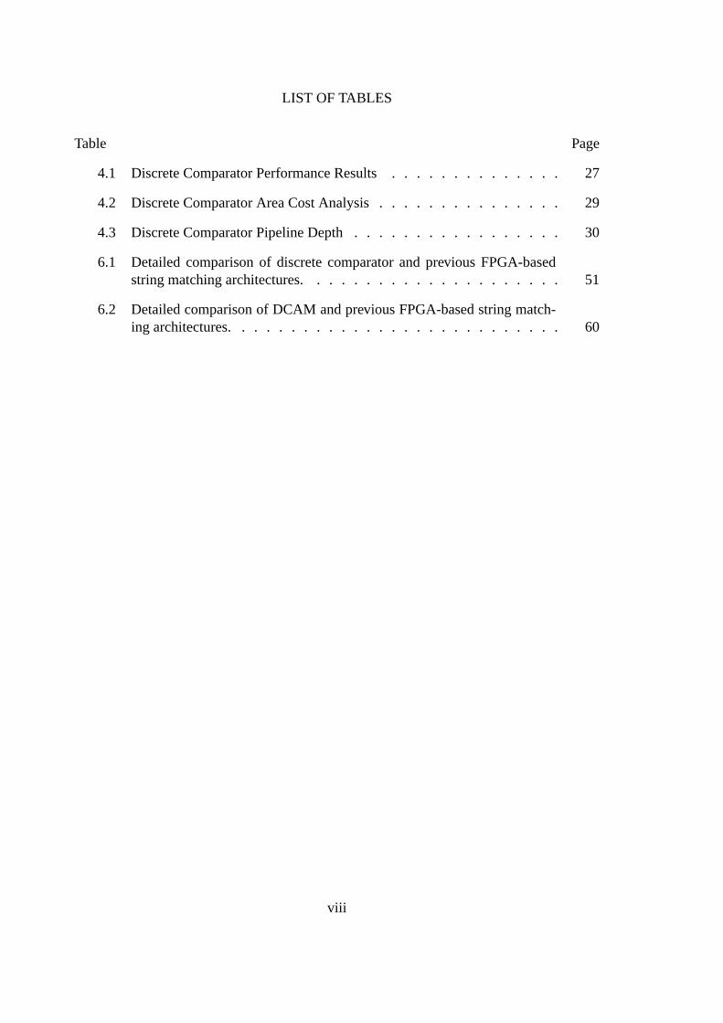
LIST OF TABLES
Table Page
4.1 Discrete Comparator Performance Results . . . . . . . . . . . . . . 27
4.2 Discrete Comparator Area Cost Analysis . . . . . . . . . . . . . . . 29
4.3 Discrete Comparator Pipeline Depth . . . . . . . . . . . . . . . . . 30
6.1 Detailed comparison of discrete comparator and previous FPGA-basedstring matching architectures. . . . . . . . . . . . . . . . . . . . . 51
6.2 Detailed comparison of DCAM and previous FPGA-based string match-ing architectures. . . . . . . . . . . . . . . . . . . . . . . . . . . 60
viii
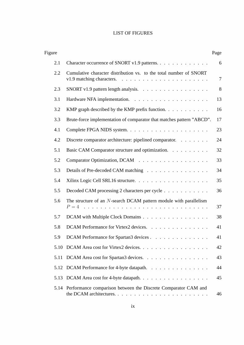
LIST OF FIGURES
Figure Page
2.1 Character occurrence of SNORT v1.9 patterns. . . . . . . . . . . . . 6
2.2 Cumulative character distribution vs. to the total number of SNORTv1.9 matching characters. . . . . . . . . . . . . . . . . . . . . . 7
2.3 SNORT v1.9 pattern length analysis. . . . . . . . . . . . . . . . . 8
3.1 Hardware NFA implementation. . . . . . . . . . . . . . . . . . . 13
3.2 KMP graph described by the KMP prefix function. . . . . . . . . . . 16
3.3 Brute-force implementation of comparator that matches pattern ”ABCD”. 17
4.1 Complete FPGA NIDS system. . . . . . . . . . . . . . . . . . . . 23
4.2 Discrete comparator architecture: pipelined comparator. . . . . . . . 24
5.1 Basic CAM Comparator structure and optimization. . . . . . . . . . 32
5.2 Comparator Optimization, DCAM . . . . . . . . . . . . . . . . . 33
5.3 Details of Pre-decoded CAM matching . . . . . . . . . . . . . . . 34
5.4 Xilinx Logic Cell SRL16 structure. . . . . . . . . . . . . . . . . . 35
5.5 Decoded CAM processing 2 characters per cycle . . . . . . . . . . . 36
5.6 The structure of anN -search DCAM pattern module with parallelismP = 4 . . . . . . . . . . . . . . . . . . . . . . . . . . . . . . 37
5.7 DCAM with Multiple Clock Domains . . . . . . . . . . . . . . . . 38
5.8 DCAM Performance for Virtex2 devices. . . . . . . . . . . . . . . 41
5.9 DCAM Performance for Spartan3 devices . . . . . . . . . . . . . . 41
5.10 DCAM Area cost for Virtex2 devices. . . . . . . . . . . . . . . . . 42
5.11 DCAM Area cost for Spartan3 devices. . . . . . . . . . . . . . . . 43
5.12 DCAM Performance for 4-byte datapath. . . . . . . . . . . . . . . 44
5.13 DCAM Area cost for 4-byte datapath. . . . . . . . . . . . . . . . . 45
5.14 Performance comparison between the Discrete Comparator CAM andthe DCAM architectures. . . . . . . . . . . . . . . . . . . . . . . 46
ix

5.15 Area cost comparison between the Discrete Comparator CAM and theDCAM architectures. . . . . . . . . . . . . . . . . . . . . . . . 47
6.1 Baker and DCAM approaches for shifting decoded data. . . . . . . . 53
6.2 DCAM compared to Baker et al. . . . . . . . . . . . . . . . . . . 54
6.3 DCAM compared to Clark et al. . . . . . . . . . . . . . . . . . . 57
6.4 DCAM compared to Cho et al. . . . . . . . . . . . . . . . . . . . 58
7.1 Shift patterns to imcrease sharing. . . . . . . . . . . . . . . . . . 66
7.2 Hybrid architecture. . . . . . . . . . . . . . . . . . . . . . . . . 67
A.1 Implementation flow. . . . . . . . . . . . . . . . . . . . . . . . 70
A.2 DCAM mapping in FPGA device, pipeline. . . . . . . . . . . . . . 72
A.3 ”Slow to Fast” and ”Fast to slow” modules for data distribution network. 73
A.4 DCAM Fan-out control. . . . . . . . . . . . . . . . . . . . . . . 74
A.5 Abstract pseudo-code that describes the shift register part of VHDL gen-erator. . . . . . . . . . . . . . . . . . . . . . . . . . . . . . . 75
A.6 Implementation of DCAM shift register part. . . . . . . . . . . . . 75
x
PUBLICATIONS OF THIS RESEARCH
The following publications resulted from this thesis research during 2003-2004:
1. Ioannis Sourdis and Dionisios Pnevmatikatos,”Fast, Large-Scale String Match for a
10Gbps FPGA-based Network Intrusion Detection System”, 13th International Con-
ference on Field Programmable Logic and Applications, Lisbon, Portugal, Septem-
ber 2003.
2. Ioannis Sourdis and Dionisios Pnevmatikatos,”Fast, Large-Scale String Match for
a 10Gbps FPGA-based NIDS”, Chapter in”New Algorithms, Architectures, and Ap-
plications for Reconfigurable Computing”, editors Wolfgang Rosenstiel and Patrick
Lysaght, Kluwer editions, 2004 (invited - to be published).
3. Ioannis Sourdis and Dionisios Pnevmatikatos,”Pre-decoded CAMs for Efficient and
High-Speed NIDS Pattern Matching”, IEEE Symposium on Field-Programmable
Custom Computing Machines (FCCM’04), 21-23 April 2004, Napa CA, USA.
xi
ABSTRACT
High speed and always-on network access is becoming commonplace around the world,
creating a demand for increased network security. Network Intrusion Detection Systems
(NIDS) attempt to detect and prevent attacks from the network using pattern-matching
rules in a way similar to anti-virus software. They check both packet header and payload
in order to detect content-based security threats. Payload scan requires efficient pattern
matching techniques, since each incoming packet must be compared against the hundreds
of known attacks. NIDS must operate at line (wire) speed so that they do not become
a bottleneck to the system’s performance. Network Intrusion Detection Systems perform
a much more efficient analysis compared to traditional firewalls, and running in general
purpose processors can serve up to a few hundred Mbps throughput.
Several ASIC commercial products have been developed, and FPGA-based archi-
tectures have been introduced, aiming at better performance as compared to software-based
systems. Although they can support high throughput, updating system ruleset and adding
new features is a difficult task for ASIC platforms. They usually trade performance for
flexibility, using large memories and integrated processors. On the other hand, reconfig-
urable devices (FPGAs) offer the required flexibility for such systems. The use of FPGA
platforms, allows easy ruleset update, adding new features, and even changing the entire
system’s architecture. Keeping the interface unchanged and not exceeding device’s capac-
ity, are the main challenges.
This thesis presents solutions for FPGA-based string matching, achieving high
throughput and reasonable area cost. The first presented architecture uses discrete com-
parators, exploits parallelism and fine-grain pipeline, allowing string matching systems
to support 8 to 11 Gbps throughput. However, this approach is costly in terms of area,
and cannot store the entire NIDS set of patterns in a single device. The next architecture
presented (DCAM) improves on the discrete comparator solution, requiring one fifth of the
initial area, while fully maintaining the performance. DCAM shares logic using centralized
character comparators (decoders), maintains performance using fine-grain pipeline, paral-
lelism, and also partitioning design into small high-speed processing engines. It also uses
xii
an advanced data distribution network to feed incoming data to pattern-matching engines
and gather out the partial matches. Finally, is shown that DCAM architecture can store
the entire set of NIDS patterns in a medium-capacity FPGA, achieving the best published
throughput, and having comparable area cost with the best published one.
xiii

1
CHAPTER 1
INTRODUCTION
The proliferation of Internet and networking applications, coupled with the wide-
spread availability of system hacks and viruses have increased the need for network secu-
rity. Firewalls have been used extensively to prevent access to systems from all but a few,
well defined access points (ports), but they cannot eliminate all security threats, nor can
they detect attacks when they happen. Stateful inspection firewalls are able to understand
details of the protocol that are inspecting by tracking the state of a connection. They actu-
ally establish and monitor connections for when it is terminated. However, current network
security needs, require a much more efficient analysis and understanding of the applica-
tion data [19]. Content-based security threats and problems occur more frequently, in an
every day basis. Virus and worm inflections, SPAMs (unsolicited e-mails), email spoofing,
and dangerous or undesirable data, get more and more annoying and cause innumerable
problems. Therefore, next generation firewalls should provide Deep Packet Inspection ca-
pabilities, in order to provide protection from these attacks. Such systems check packet
header, rely on pattern matching techniques to analyze packet payload, and make decisions
on the significance of the packet body, based on the content of the payload.
1.1 Motivation
Network Intrusion Detection Systems (NIDS) perform deep packet inspection. They scan
packet’s payload looking for patterns that would indicate security threats. Matching every
incoming byte, though, against thousands of pattern characters at wire rates is a compli-
cated task. Measurements on SNORT show that 31% of total processing is due to string
matching; the percentage goes up to 80% in the case of Web-intensive traffic [20]. So, string
matching can be considered as one of the most computationally intensive parts of a NIDS
and in this thesis we focus on payload matching. Many different algorithms or combination

2
of algorithms have been introduced and implemented in general purpose processors (GPP)
for fast string matching[16, 20, 42, 35, 3, 2], using mostly SNORT opensource NIDS rule-
set [38, 41]. However, intrusion detection systems running in GPP can only serve up to a
few hundred Mbps throughput. Therefore, seeking for hardware-based solutions is possibly
the only way to increase performance for speeds higher than a few hundred Mbps.
Until now several ASIC commercial products have been developed [31, 30, 27,
28, 29, 32]. These systems can support high throughput, but constitute a relatively ex-
pensive solution. On the other hand, FPGA-based systems provide higher flexibility and
comparable to ASICs performance. FPGA-based platforms can exploit the fact that the
NIDS rules change relatively infrequently, and use reconfiguration to reduce implementa-
tion cost. In addition, they can exploit parallelism in order to achieve satisfactory process-
ing throughput. Several architectures have been proposed for FPGA-based NIDS, using
regular expressions (NFAs/DFAs) [40, 34, 36, 22, 14, 15], CAM [23], discrete compara-
tors [13, 12, 7, 6, 5, 43, 44], and approximate filtering techniques [4, 18]. Generally, the
performance results of FPGA systems are promising, showing that FPGAs can be used to
support the increasing needs for network security. FPGAs are flexible, reconfigurable, pro-
vide hardware speed, and therefore, are suitable for implementing such systems. On the
other hand, there are several issues that should be faced. Large designs are complex and
therefore hard to operate at high frequency. Additionally, matching a large number of pat-
terns has high area cost, so sharing logic is critical, since it could save a significant amount
of resources, and make designs smaller and faster.
1.2 Scope of this thesis
Since string matching is the most computationally intensive part of an NIDS, our proposed
architectures exploit the benefits of FPGAs to design efficient string matching systems.
The proposed architectures can support between 3 to 10 Gbps throughput, storing an entire
NIDS set of patterns in a single device. In this thesis we suggest solutions to maintain
high performance and minimize area cost, show also how pattern matching designs can
3
be updated and partially or entirely changed, and advocate that bruteforce solutions can
offer high performance, while require low area. Techniques such as fine-grain pipelin-
ing, parallelism, partitioning, and pre-decoding are described, analyzing how they affect
performance and resource consumption.
This thesis provides two CAM-like architectures for efficient and high-speed string
matching. It also evaluates our solutions in terms of performance and cost, discusses its
advantages and drawbacks, compares it with related architectures, and presents possible
improvements and alternative solutions. Developing VHDL representation of large designs
that store hundreds of patterns is a time-consuming procedure. Therefore, it is important
to automatically generate the VHDL code of a design that stores a particular set of pat-
terns. This work describes an automatic implementation methodology for the proposed
architecture, in order to generate the desired design fast.
1.3 Dissertation Outline
The rest of the thesis is organized as follows: the next chapter presents o brief description
of NIDS , offers some statistics about the patterns contained in a NIDS, and present some
performance results of software-based NIDS. Chapter 3 describes hardware-based NIDSs,
previous FPGA-based pattern matching architectures, and commercial products. In chap-
ters 4 and 5), our initial Discrete Comparator approach and our final DCAM architecture
are introduced respectively, presenting also implementation results in terms of area cost
and performance. In chapters 6 we attempt a fair comparison between our architectures
and related work, and in chapter 7 we present the conclusions of this work and discuss
future extensions. Finally, Appendix A shows our implementation methodology and other
implementation details.
4
CHAPTER 2
SOFTWARE-BASED PACKET INSPECTION
This chapter includes a brief description of intrusion detection systems and their rule syn-
tax. Further, there is an analysis of the NIDS patterns used, trying to extract useful infor-
mation about which pattern matching approach would be more appropriate, and efficient.
Finally, the last section describes intrusion detection systems running in general purpose
processors, using efficient string matching algorithms.
2.1 Intrusion Detection Systems
Network Intrusion Detection Systems (NIDS) attempt to detect attacks by monitoring in-
coming traffic for suspicious contents. They collect data from network, monitor activity
across network, analyze packets, and report any intrusive behavior in an automated fash-
ion. Intrusion detection systems use advanced pattern matching techniques (i.e. Boyer and
Moore [10], Aho and Corasick [1], Fisk and Varghese [20]) on network packets to iden-
tify known attacks. They use simple rules (or search patterns) to identify possible security
threats, much like virus detection software, and report offending packets to the administra-
tors for further actions. NIDSs should be updated frequently, since new signatures may be
added or others may change on a weekly basis.
NIDS rules usually refer to the header as well as to the payload of a packet. Header
rules check for equality (or range) in numerical fields and are straightforward to implement.
More computationally-intensive is the text search of the packet payload against hundreds
of patterns that must be performed at wire-speed [17, 16].
SNORT is an open-source NIDS that has been extensively used and studied in the
literature [41, 38, 17]. Based on a rule database, SNORT monitors network traffic and
detects intrusion events. Many researchers developed string matching algorithms, com-
bination of algorithms and techniques such as pre-filtering in order to improve SNORT’s
5
performance[16, 20, 42, 35, 3, 2]. Section 2.3 describes these algorithms and techniques,
and also evaluates their performance, which is lower compared to hardware intrusion de-
tection systems.
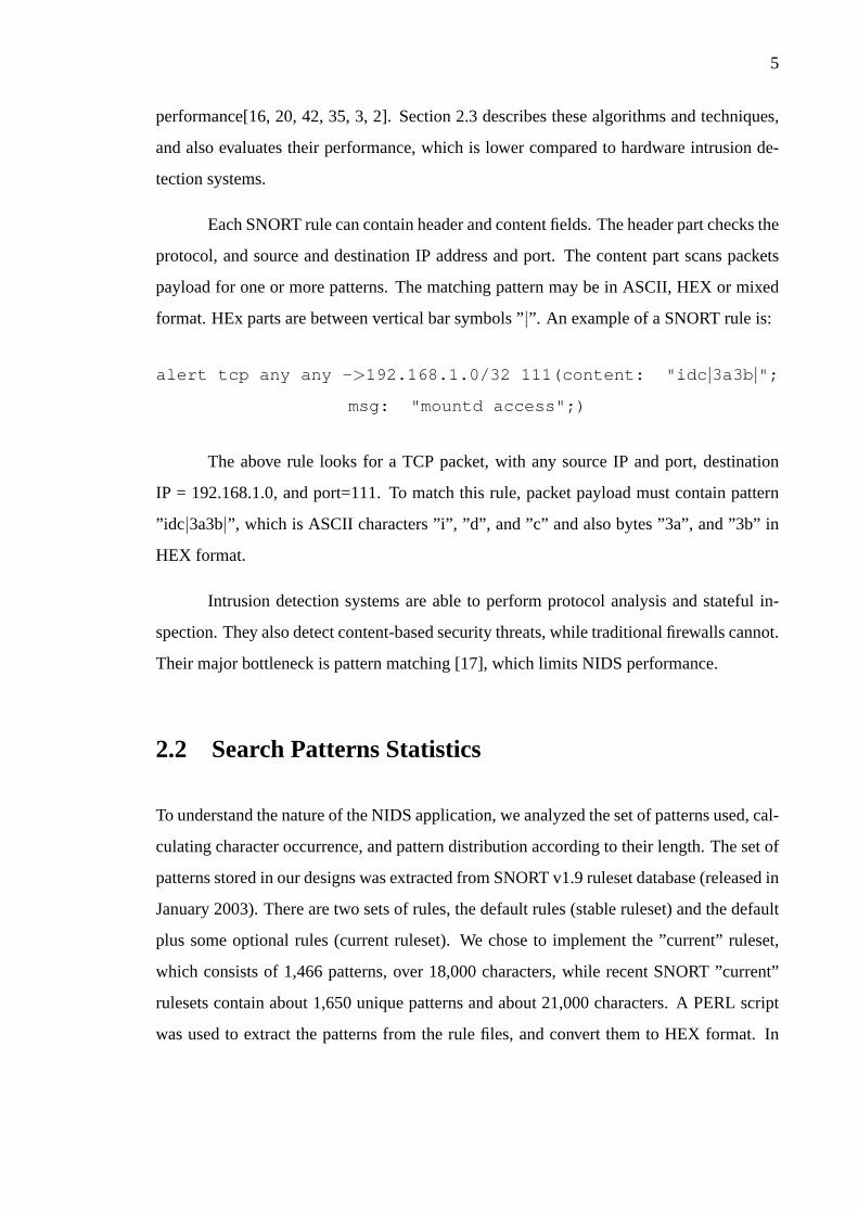
Each SNORT rule can contain header and content fields. The header part checks the
protocol, and source and destination IP address and port. The content part scans packets
payload for one or more patterns. The matching pattern may be in ASCII, HEX or mixed
format. HEx parts are between vertical bar symbols ”|”. An example of a SNORT rule is:
alert tcp any any - >192.168.1.0/32 111(content: "idc |3a3b |";msg: "mountd access";)
The above rule looks for a TCP packet, with any source IP and port, destination
IP = 192.168.1.0, and port=111. To match this rule, packet payload must contain pattern
”idc|3a3b|”, which is ASCII characters ”i”, ”d”, and ”c” and also bytes ”3a”, and ”3b” in
HEX format.
Intrusion detection systems are able to perform protocol analysis and stateful in-
spection. They also detect content-based security threats, while traditional firewalls cannot.
Their major bottleneck is pattern matching [17], which limits NIDS performance.
2.2 Search Patterns Statistics
To understand the nature of the NIDS application, we analyzed the set of patterns used, cal-
culating character occurrence, and pattern distribution according to their length. The set of
patterns stored in our designs was extracted from SNORT v1.9 ruleset database (released in
January 2003). There are two sets of rules, the default rules (stable ruleset) and the default
plus some optional rules (current ruleset). We chose to implement the ”current” ruleset,
which consists of 1,466 patterns, over 18,000 characters, while recent SNORT ”current”
rulesets contain about 1,650 unique patterns and about 21,000 characters. A PERL script
was used to extract the patterns from the rule files, and convert them to HEX format. In
6
Character Occurrence
0
100
200
300
400
500
600
700
800
900
1000
1100
1200
0 20 40 60 80 100 120 140 160 180 200 220 240
ASCII values
# o
c c
u r r e n
c e
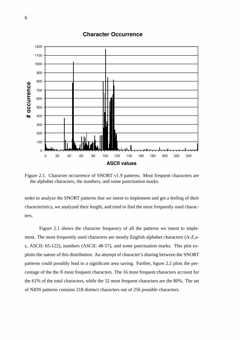
Figure 2.1. Character occurrence of SNORT v1.9 patterns. Most frequent characters arethe alphabet characters, the numbers, and some punctuation marks.
order to analyze the SNORT patterns that we intent to implement and get a feeling of their
characteristics, we analyzed their length, and tried to find the most frequently used charac-
ters.
Figure 2.1 shows the character frequency of all the patterns we intent to imple-
ment. The most frequently used characters are mostly English alphabet characters (A-Z,a-
z, ASCII: 65-122), numbers (ASCII: 48-57), and some punctuation marks. This plot ex-
ploits the nature of this distribution. An attempt of character’s sharing between the SNORT
patterns could possibly lead to a significant area saving. Further, figure 2.2 plots the per-
centage of the theN most frequent characters. The 16 most frequent characters account for
the 61% of the total characters, while the 32 most frequent characters are the 80%. The set
of NIDS patterns contains 218 distinct characters out of 256 possible characters.

7
Characters sorted by occurrence
0%
25%
50%
75%
100%
1 17 33 49 65 81 97 113 129 145 161 177 193 209 225 241
p e
r c e n
t a g e
Number of distinct characters
Figure 2.2. Cumulative character distribution versus to the total number of matching char-acters.
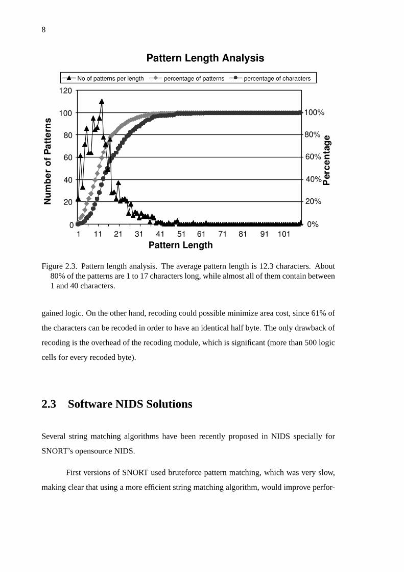
The pattern length is between 1 to 107 characters, while the average size of each
pattern is 12.3 characters. Most patterns contain less than 20 characters, while 80% of the
patterns are 1 to 17 characters long, and almost all of them (99.5%) have less than 40 bytes
length. Half of the matched characters are included in patterns less than 15 bytes long, and
patterns with less than 50 bytes contain almost all of the matching characters (99%).
One of our first ideas for FPGA-based string match, was to recode or encode the
incoming data (i.e Huffman encoding [26]). This idea would possibly be interesting if the
most frequently used characters could be encoded in 4 bits or less. That is because of the
FPGAs’ structure, the smallest logic element of devices can implement logic functions that
have 4 bits input in a 4-input LUT. Otherwise, two or more logic cells are needed. So, in
order to use fewer logic cells for the matching, the encoded bits must be less than 5.The
16 most frequently used characters (can be encoded in 4 bits), account for 61% of the total
number of characters. However, Huffman encoding would possibly not offer considerable
potential, since even if for these most frequent characters a designer could half the cost of
matching, the overhead for matching the rest of the characters would be about equal to the
8
Pattern Length Analysis
0
20
40
60
80
100
120
1 11 21 31 41 51 61 71 81 91 101
Pattern Length
N u
m b
e r
o f
P a t t
e r n
s
P e
r c e
n t a
g e
No of patterns per length percentage of patterns percentage of characters
0%
20%
40%
60%
80%
100%
Figure 2.3. Pattern length analysis. The average pattern length is 12.3 characters. About80% of the patterns are 1 to 17 characters long, while almost all of them contain between1 and 40 characters.
gained logic. On the other hand, recoding could possible minimize area cost, since 61% of
the characters can be recoded in order to have an identical half byte. The only drawback of
recoding is the overhead of the recoding module, which is significant (more than 500 logic
cells for every recoded byte).
2.3 Software NIDS Solutions
Several string matching algorithms have been recently proposed in NIDS specially for
SNORT’s opensource NIDS.
First versions of SNORT used bruteforce pattern matching, which was very slow,
making clear that using a more efficient string matching algorithm, would improve perfor-
9
mance. The first implementations that improved SNORT used the Boyer-Moore algorithm
[10], and later a”2-dimentional linked list with recursive node walking”. This implemen-
tation improved SNORT performance 200-500% [41]. The Boyer-Moore algorithm is one
of the most well-known algorithms that uses two heuristics to reduce the number of com-
parisons. It first aligns the pattern and the incoming data (text), the comparison begins from
the right-most character, and in case of mis-match the text is properly shifted.
However, the Boyer-Moore algorithm compares each pattern independently against
the incoming data, and hence substrings repeated in more than one patterns are compared
multiple times. Coit et al.[16] implemented a”Boyer-Moore Approach to Exact Set Match-
ing” , described by Gusfield [24]. They called it ACBM algorithm, since all the patterns
are stored in an Aho-Corassick-like tree [1]. Using this tree Coit et al. reduced the many
unnecessary comparisons, and improved SNORT performance 1.02-3.32 times. Similarly
to Coit et al., Fisk et al. [20] introduced Set-wise Boyer Moore-Hospool algorithm, which
is an adaptation of Boyer-Moore, and is shown to be faster for matching less than 100
patterns.
Another implementation of SNORT is presented in [42], and uses Wu-Mander
multi-pattern matching algorithm [45]. The MWM algorithm performs a hash on 2-character
prefix of he input data, in order to index into a group of patterns. This SNORT implemen-
tation is much faster than previous ones.
Finally, Markatos et al. proposedE2xB algorithm, which provides quick nega-
tives when the search pattern does not exist in the incoming data[35, 3, 2]. Compared to
Fisk et al.,E2xB is faster, while for large incoming packets and less than 1k-2k rules it
outperforms MWM [3].
All the above software-based approaches can support a few hundred Mbps at most.
That’s 2-10 times slower compared to older FPGA-based string matching systems, and 10-
30 times slower compared to recent FPGA-based string matching architectures (including
our research, chapters 4, 5, and 6).

10
CHAPTER 3
HARDWARE-BASED PACKET INSPECTION
Software-based Intrusion Detection Systems can only support modest throughput. On the
other hand, hardware can easily adapt in NIDS application needs, achieving better perfor-
mance with reasonable cost. In this chapter, we investigate various hardware-based solu-
tions for string matching. Several companies such as Cisco, NetScreen and PMC-Sierra
produce firewalls, or else called ASIC security programmable co-processors. Additionally,
much work has been done in FPGA-based string matching for NIDS, since FPGAs give
the advantage of reconfiguration. All these ASIC and FPGA-based approaches offer much
better performance as compared to software solutions.
3.1 Hardware-based String Matching & Packet Inspec-
tion
Given the processing bandwidth limitations of General purpose processors (GPP), which
can serve only a few hundred Mbps throughput, H/W-based NIDS (ASIC or FPGA) is an
attractive alternative solution. Many ASIC intrusion detection systems have been com-
mercially developed [31, 30, 27, 28, 29, 32]. Such systems usually store their rules using
large memory blocks, and examine incoming packets in integrated processing engines.
Generally, ASICs programmable security co-processors are expensive, complicated, and
although they can support higher throughput compared to GPP, they do not achieve impres-
sive performance. The memory blocks that store the NIDS rules are re-loaded, whenever
an updated ruleset is available. The most common technique for pattern matching in ASIC
intrusion detection systems is the use of regular expressions[31, 30, 32]. Updating the rule-
set is not a trivial procedure, since the system must be able to support a variation of rules,
with sometimes complex syntax, and special features. On the other hand, FPGAs are more
suitable, because they are reconfigurable, they provide H/W speed and exploit parallelism.
11
An FPGA-based system can be entirely changed with only the reconfiguration overhead,
by just keeping the interface constant. This characteristic of reconfigurable devices allows
updating or changing the ruleset, adding new features, even changing systems architec-
ture, without any hardware cost. There are two approaches about the rule-set update of
an FPGA-based NIDS. A convenient solution is to reconfigure the entire device in order
to change existing rules or add new ones. However, this is a time-consuming procedure,
specially considering that it may take place in week basis, since it requires a few hours to
generate the new bitstream and a few minutes to drop the entire system during reconfigu-
ration. On the other hand, if an initial Placed & Routed design already exists, and only a
small part of it has changed, then incremental MAP and P&R is much more effective and
quick. Incremental flow uses guide files of the initial design, and hence needs less time to
complete. Another solution is to partially reconfigure the device. This approach is faster,
can instantly swap the new submodule, and in case of new device families, it is possible
not to lose the incoming and outgoing data of the submodule[46]. In the following sections
several architectures of FPGA-based string matching systems, and some ASIC commercial
products are presented.
3.2 FPGA-based String Matching
One of the first attempts in string matching using FPGAs, presented in 1993 by Pryor, This-
tle and Shirazi [37]. Their algorithm, implemented on Splash-2 platform, and succeeded
to perform a dictionary search, without case sensitivity patterns, that consisted of English
alphabet characters (26 characters). Pryor et al. managed to achieve great performance
and perform a low overhead AND-reduction of the match indicators using hashing. Since
1993, many others have worked on implementing FPGA-based string match systems.In the
rest of this chapter we describe several previous published architectures of hardware-based
string matching systems for network intrusion detection systems. Most researchers de-
signed there pattern matching architectures based on regular expressions (NFAs and DFAs)
[40, 22, 36, 14]. This is a low cost solution, but does not achieve very high performance.

12
It is also difficult to process more than one character per cycle, and usually the operat-
ing frequency is limited by the amount of combinational logic for state transitions. Other
researchers preferred to follow a more straightforward approach, using CAMs or discrete
comparators to search payload against the patterns contained in NIDS ruleset [23, 13, 11].
In this case the area cost is higher, but performance is significantly better, because it is
easier to pipeline logic and process multiple bytes per cycle. A widely used technique to
increase sharing and reduce designs cost is the use of pre-decoding, which was applied to
both regular expression and CAM-like appraches[15, 12, 6, 5]. Pre-decoding has recently
introduced and used by several research groups. It is based on the idea that incoming
data are pre-decoded in centralized decoders, so that each unique character is matched
only once. A more efficient and very low cost approach was presented by Dharmapurikar
et al. who implemented Bloom Filters to perform string matching [18]. Knuth-Morris-
Pratt string matching algorithm was also used by Sidhu and Prasanna[39] and Baker and
Prasanna [7]. Finally,the last section of this chapter talks about commercial products that
have been developed for deep packet inspection.
3.2.1 NonDeterministic/Deterministic Finite Automata
The most common approach is the regular expressions matching, implemented using Finite
Automata (NFAs or DFAs)[40, 22, 36, 14]. Regular expressions produce designs with low
cost, but at a modest throughput. The basic idea of is to generate regular expressions for
every pattern or group of patterns, and implement them with N/DFA.
A regular expression is a pattern that describes one or more strings. It consists of
characters, which are considered as regular expressions, andmetacharacters(|,*,(,),) that
have special use. Regular expression syntax includes the following rules:
• ab, a followed by b.
• a|b, a or b.
• a*, zero, one, or more a.
13
• ε is the empty string.
There are also other meta-characters that lead to more complex syntaxes, and more efficient
regular expressions.
Non-deterministic Finite Automata (NFAs) are direct graphs, their nodes are states,
and their edges are labeled with a character orε [21]. There is aninitial and one or more
final states. On the other hand, Deterministic Finite Automata (DFAs) are similar to NFAs,
but they do not includeε characters. Additionally, only one state can be active in DFAs,
while NFAs can have more than one active states. Generally, NFAs are simpler and easier to
design by just listing all stored patterns. On the other hand, DFAs are easier to implement,
because there are no choices to be considered, since there are noε characters and there
is only one state active. Theoretically, DFA can be exponentially larger than NFA, but in
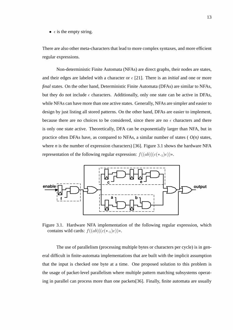
practice often DFAs have, as compared to NFAs, a similar number of states (O(n) states,
wheren is the number of expression characters) [36]. Figure 3.1 shows the hardware NFA
representation of the following regular expression:f((ab)|(c(∗.1)e))∗.
enable
f
c e
a b
output
Figure 3.1. Hardware NFA implementation of the following regular expression, whichcontains wild cards:f((ab)|(c(∗.1)e))∗.
The use of parallelism (processing multiple bytes or characters per cycle) is in gen-
eral difficult in finite-automata implementations that are built with the implicit assumption
that the input is checked one byte at a time. One proposed solution to this problem is
the usage of packet-level parallelism where multiple pattern matching subsystems operat-
ing in parallel can process more than one packets[36]. Finally, finite automata are usually

14
restricted in their operating frequency by the amount of combinational logic for state tran-
sitions. In many cases the equations are complex, resulting in multilevel implementations
even with FPGA 4-to-1 LUTs.
In 1982, Floyd and Ullman were the first who implemented NFAs in hardware,
using PLA (Programmable logic array) [25]. In 2001, Sidhu and Prassanna [40] introduced
regular expressions and Nondeterministic Finite Automata (NFAs) for finding matches to
a given regular expression. They focused in minimizing the space -O(n2)- required to
perform the matching, and their automata matched one text character per clock cycle. For
a single regular expression, the constructed NFAs and FPGA circuit was able to process
each text character in 17.42-10.70ns (57.5-93.5 MHz) using a Virtex XCV100 FPGA.
One year later, Franklin, Carver and Hutchings [22] expanding on Sidhu et al. work,
used regular expressions, with more complex syntax and meta-characters such as ”?” and
”.”, to describe patterns extracted from Snort database. Using a sequence of 8-bit character
matchers they compose the NFA circuit. Each 8-bit comparator fits in a single slice (two
logic cells). Every LUT matches half of the pattern character. The previous output is stored
in a flip-flop and rerouted back into the slice through the carry chain resources, it is AND-
ed with the match signal of the LS half-byte and the result is finally AND-ed with the MS
half-byte result to produce the slice output. Franklin et al. were the first that mentioned
the performance bottleneck that occurs in such systems due to large fan-out. The main
drawback is the routing delay of the comparators outputs that input to every single slice
used in character matching. Their solution was to arrange flip-flops in a fan-out tree. They
managed to include up to 16,000 characters1 requiring 2.5-3.4 logic cells per matching
character. The operating frequency of the synthesized modules was about 30-100 MHz on
a Virtex XCV1000 and 50-127 MHz on a Virtex XCV2000E, and in the order of 63.5 MHz
and 86 MHz respectively on XCV1000 and XCV2000E for a few tens of rules.
In 2003, Moscola, Lockwood et al. used the Field Programmable Port Extender
(FPX) platform, to perform string matching for an Internet firewall [36]. They used regu-
1non-Meta characters, size of regular expression
15
lar expressions (DFAs) to store the patterns. Each regular expressions is parsed and sent
through JLex [8] to get a representation of the DFA required to match the expression. Fi-
nally, JLEx representation is converted to VHDL. Their processing engine processes one
byte during every cycle. Incoming packet data is stored in two identical buffers. The first
buffer is used to feed the parallel DFA matchers with 8-bit packet data. The second buffer
stores the incoming packets until the content scanners indicate whether to output or drop
a packet. This implementation can operate at 37 MHz on a Virtex XCV2000E and serve
296 Mbps (8bits ∗ 37MHz = 296Mbps). Moscola et al. finally described a technique
to increase processing bandwidth. Incoming packets arrive in 32-bit words, and are dis-
patched to one of the four content scanners. However, using packet parallelism where
multiple copies of the match module scan concurrently different packets, may not offer the
guaranteed processing bandwidth, due to the variable size of the IP packets. This solution
quadruples design’s throughput (1.184 Gbps).
Lockwood also implemented a sample application on FPX constructing a small
FSM[34]. Lockwood’s FSM could match 4 incoming packet characters in a single clock
cycle. Because of its large input width, this approach is practically unsuitable to implement
for many patterns and even more for complicated DFAs. Their circuit operates at 119 MHz
on a Virtex V1000E-7 device and has 3.8 Gbps throughput.
In the same year, Clark and Schimmel [14] developed a pattern matching coproces-
sor that supports the entire SNORT rule-set using NFAs. In order to reduce design area they
used centralized decoders instead of character comparators for the NFA state transitions.
Their design processes one character per cycle, can match over 1,500 patterns (17,537 char-
acters), and requires about 1.1 logic cells per matched character. Its operating frequency is
100 MHz having total throughput 0.8 Gbps in a Virtex-1000 device. In FCCM 2004, Clark
and Schimmel expanded on their earlier work implementing designs that process multiple
incoming bytes per cycle. Their detailed results proved that NFAs and pre-decoding can
produce low cost designs with higher performance, compared to DFAs and simple brute-
force approaches.
16
3.2.2 Knuth-Morris-Pratt Algorithm
One of the must well known algorithms for string matching is Knuth-Morris-Pratt algo-
rithm [33]. While there are other algorithms that have better performance in average case,
KMP algorithm provides better worst case delay.
KMP algorithm, first, constructs a prefix function for the matching pattern. This
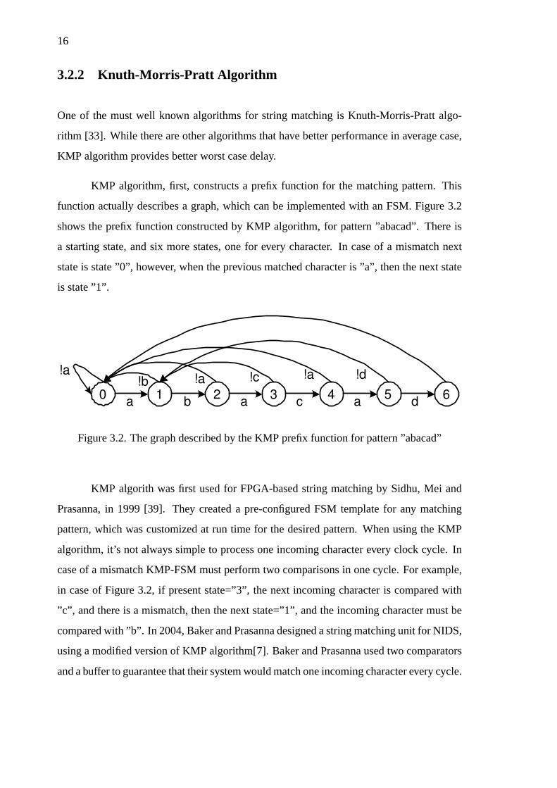
function actually describes a graph, which can be implemented with an FSM. Figure 3.2
shows the prefix function constructed by KMP algorithm, for pattern ”abacad”. There is
a starting state, and six more states, one for every character. In case of a mismatch next
state is state ”0”, however, when the previous matched character is ”a”, then the next state
is state ”1”.
0 1 4 3 2 5 6 a
!a
d a c a b
!d !a !c !a !b
Figure 3.2. The graph described by the KMP prefix function for pattern ”abacad”
KMP algorith was first used for FPGA-based string matching by Sidhu, Mei and
Prasanna, in 1999 [39]. They created a pre-configured FSM template for any matching
pattern, which was customized at run time for the desired pattern. When using the KMP
algorithm, it’s not always simple to process one incoming character every clock cycle. In
case of a mismatch KMP-FSM must perform two comparisons in one cycle. For example,
in case of Figure 3.2, if present state=”3”, the next incoming character is compared with
”c”, and there is a mismatch, then the next state=”1”, and the incoming character must be
compared with ”b”. In 2004, Baker and Prasanna designed a string matching unit for NIDS,
using a modified version of KMP algorithm[7]. Baker and Prasanna used two comparators
and a buffer to guarantee that their system would match one incoming character every cycle.
17
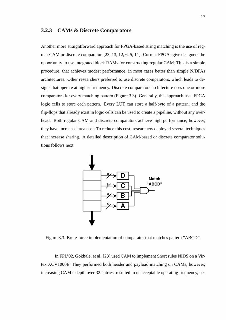
3.2.3 CAMs & Discrete Comparators
Another more straightforward approach for FPGA-based string matching is the use of reg-
ular CAM or discrete comparators[23, 13, 12, 6, 5, 11]. Current FPGAs give designers the
opportunity to use integrated block RAMs for constructing regular CAM. This is a simple
procedure, that achieves modest performance, in most cases better than simple N/DFAs
architectures. Other researchers preferred to use discrete comparators, which leads to de-
signs that operate at higher frequency. Discrete comparators architecture uses one or more
comparators for every matching pattern (Figure 3.3). Generally, this approach uses FPGA
logic cells to store each pattern. Every LUT can store a half-byte of a pattern, and the
flip-flops that already exist in logic cells can be used to create a pipeline, without any over-
head. Both regular CAM and discrete comparators achieve high performance, however,
they have increased area cost. To reduce this cost, researchers deployed several techniques
that increase sharing. A detailed description of CAM-based or discrete comparator solu-
tions follows next.
8
A
B
C
D Match
“ABCD”
8
8
8
Figure 3.3. Brute-force implementation of comparator that matches pattern ”ABCD”.
In FPL’02, Gokhale, et al. [23] used CAM to implement Snort rules NIDS on a Vir-
tex XCV1000E. They performed both header and payload matching on CAMs, however,
increasing CAM’s depth over 32 entries, resulted in unacceptable operating frequency, be-
18
cause of routing limitations. Their hardware runs at 68MHz with 32-bit data every clock
cycle, giving a throughput of 2.2 Gbps, and reported a 25-fold improvement on the speed
of Snort v1.8 on a 733MHz PIII and an almost 9-fold improvement on a 1 GHz PowerPC
G4.
Closer to our work described in chapter 4 is the work by Cho, Navab and Mangione-
Smith [13], also presented in FPL’02. They designed a deep packet filtering firewall on
a FPGA and automatically translated each pattern-matching component into structural
VHDL. They presented a block diagram of a complete FPGA-based NIDS, and imple-
mented the content pattern matching unit for more than a hundred signatures. The content
match micro-architecture used 4 parallel comparators for every pattern so that the system
advances 4 bytes of input packet every clock cycle. In Cho’s et al. architecture, incoming
packet data is partially matched sequential 4-byte comparators, and finally the results of the
four parallel comparators are OR-ed. The design implemented in an Altera EP20K device
runs at 90MHz, achieving 2.88 Gbps throughput. They require about 10 logic cells per
search pattern character. However, they do not include the fan-out logic that we have (see
chapter 4), and do not encode the matching rule. Instead they just OR all the match signals
to indicate that some rule matched.
In FCCM’04, Cho and Mangione-Smith improved their earlier architecture and also
introduced ROM-based filtering in [12]. They shared sub-string comparators reducing the
area cost. They used centralized decoders for character matching and combined the partial
matches using priority encoder. The introduced architecture needs about 6 times less area
as compared to the initial one, while maintaining performance. The ROM-based solution
uses a comparator to match the initial part of the incoming data and uses the matched
prefix as an address into a ROM in order to read the rest of the pattern. After that, the
suffix of the pattern is matched against the incoming payload. However, this technique has
limitations, first because ROM can only store patterns with different prefixes and second
due to the extra memory resources needed to store the length of every suffix. Despite these
limitations, using the ROM-based solution, Cho and Mangione-Smith managed to store
one third of the rules and further reduce the area cost of their design.

19
Another CAM-based solution using pre-decoding was introduced by Baker and
Prasanna in the same conference (FCCM’04)[6]. They tried to achieve high performance
even for large rule-set designs using partitioning. They performed complex pattern prepro-
cessing in order to group together patterns with similarities and minimize area cost. So,
Baker and Prasanna introduced a graph-based representation of the problem and used a
mincut solution to group patterns. Baker’s et al. system decodes incoming data, properly
delays decoded data and finally ANDs them to produce a ”match” signal for every stored
pattern. This micro-architecture is very similar to ours presented also in FCCM’04 (see
chapter 5). In this work they also presented a ”Pre-filtering” architecture that processes
multiple incoming bytes (4 bytes), while using a one-byte datapath, and hence has low
area cost. However, this approach allows false-positives, and this is what this architecture
trades for reducing the area cost. A few months later, Baker and Prasanna presented a tree-
based hardware reuse strategy[5]. This approach, partially matches pattern’s substrings,
and finally ANDs the partial results. Tree-based solution, allows sharing entire substring
matchers, and slightly reduces even more the design area.
3.2.4 Approximate Filtering
Another solution that reduces matching cost is the use of approximate filtering techniques
such as Bloom filters and generally hash functions. Such algorithms succeed to reduce the
number of matching bits, however, due to the nature of these techniques, false positives may
occur and hence exact string matching is required. Sometimes researchers use additional
submodules to perform exact matching, and usually these modules support much lower
throughput as compared to approximate filtering engines. Sometimes hackers use methods
to overload NIDS with packets that match NIDS rules. In these cases, systems that use
approximate filtering techniques and also perform exact matching either cannot support the
needed throughput or just drop more packets than they should. Another drawback is that
for every pattern length a different processing engine is needed.
Lockwood’s research group from Washington University of St. Louis introduced

20
the use of Bloom filters for FPGA-based sting matching in packet inspection systems [18,
4]. A Bloom filter (BF) computes a number of hash functions on it producing ak-bit vector,
which is much smaller compared to the input data. Lockwood et al. implemented a Bloom
filter module using five parallel different BFs to decrease the probability of false positives
(P = (1/2)10). Every BF supports patterns of the same length, therefore many parallel BFs
are needed. In order to increase processing bandwidth, a very common technique [13, 43]
was implemented, multiple engines are used in parallel each monitoring a window of bytes
with different offset.
Although every Bloom filter can store 1419 signatures, all signatures must be of the
same length. This constitutes a major drawback since it increases the need of internal block
RAMs. Their design implemented 9 BFs that match 2-26 byte patterns, it operates at 63
MHz, corresponding to a throughput of 502 Mbps without parallelism and over 2 Gbps if
4 parallel engines were used.
3.3 ASICs - Commercial Products
There are several commercial platforms that perform payload matching to prevent data-
driven attacks. Safenet, Netscreen, PMC-Siera, Broadcom, TippingPoint and Cisco are
some of the firewall vendors who created co-processors that offer deep packet inspection
[31, 30, 27, 28, 29, 32]. These products can support between a few hundred Mbps to 2.5
Gbps throughput. However, their increased cost offsets their efficiency. A small description
about these proprietary systems follows, since only few details are available.
SafeNet’s SafeXcel-4850 [31] is a content inspection co-processor that can support
320 Mbps throughput and stores up to 1500 rules. SafeXcel 4850-PCI can be used as a
plug-in card in a host or server enviroment. It contains four internal processing engines.
Each engine has an external interface to a ZBT SRAM memory bank. These memory banks
store the compiled regular expression rules that are used for matching against input data
packets. Through the PCI interface, the host downloads the compiled rules to the SafeXcel-

21
4850, sends data packets and reads back match results. A Regular Expression compiler
reads a list of user-defined regular expression rules and target memory map locations for
the SafeXcel-4850, and generates a binary output file, which then gets downloaded to the
SafeXcel-4850 and external memory. Once the compiled rules are downloaded, packets
can be sent and match results can be read to and from the SafeXcel-4850.
NetScreen developed the Intrusion Detection and Prevention (IDP) system, which
supports payload analysis [29]. NetScreen-IDP can store a few hundreds of contents and
serve between 20 Mbps to 1 Gbps throughput. PMC-Siera ClassiPi is a network classifica-
tion processor that performs packet classification and analysis up to OC48 (2.5 Gbps) rates
[30]. It provides forward and reverse content searches, single or multiple match identifica-
tion, and prioritized match selection on multiple matches. The Fast filter processor (FFP)
of Broadcom’s StrataSwitch II offers a limited analysis of the application data [27]. Broad-
com’s FFP processing engine examines up to the 80th byte of an incoming packet in order
to support intrusion detection applications. Cisco PIX 500 Series firewalls (535, 525, 506E,
501) offer limited protection from data-driven attacks, and they provide 10 to 1700 Mbps
of firewall throughput [28]. ”Fixup” commands of Cisco’s PIX provide some deep packet
inspection capabilities [19]. Finally, TippingPoint’s intrusion prevention system that uses
regular expressions for payload matching [32]. TippingPoint’s UnityOne series is capable
to serve 50Mbps to 2 Gbps throughput.
22
CHAPTER 4
DISCRETE COMPARATORS
The first architecture, presented in this thesis, uses discrete comparators for pattern match-
ing [43]. The entire design is fully pipelined, exploits parallelism to increase processing
bandwidth, and uses a fast fan-out tree to distribute the incoming data to each compara-
tor. Detailed performance and area results are presented, showing that discrete comparator
approach achieves high throughput, but has significant area cost.
4.1 Discrete Comparators Architecture
The architecture of an FPGA-based NIDS system includes blocks that match header fields
rules, and blocks that perform text match against the entire packet payload. Of the two,
the computationally expensive module is the text match. In this work we assume that it it
relatively straightforward to implement the first module(s) at high speed since they involve
a comparison of a few numerical fields only, and focus in making the pattern match module
as fast as possible.
If the text match operates at one (input) character per cycle, the total throughput is
limited by the operating frequency. To alleviate this bottleneck, other researchers suggested
using packet parallelism where multiple copies of the match module scan concurrently
different packets [36]. However, due to the variable size of the IP packets, this approach
may not offer the guaranteed processing bandwidth. Instead, we use discrete comparators
to implement a CAM-like functionality. Since each of these comparators is independent,
we can use multiple instances to search for a pattern in a wider datapath. A similar approach
has been used in [13].
The results of the system are (i) an indication that there was indeed a match, and
(ii) the number of the rule that did match. Our architecture uses fine grain pipeline for all
sub-modules: fan-out of packet data to comparators, the comparators themselves, and for
23
Packet
Packet body
Packet header
Shift Register 0
1
3
CMP
CMP
CMP 2
CMP
E n
c o d
e
r Packet body
Packet header
Shift Register
Fan-out
Tree
0
1
3
CMP
CMP
CMP 2
CMP
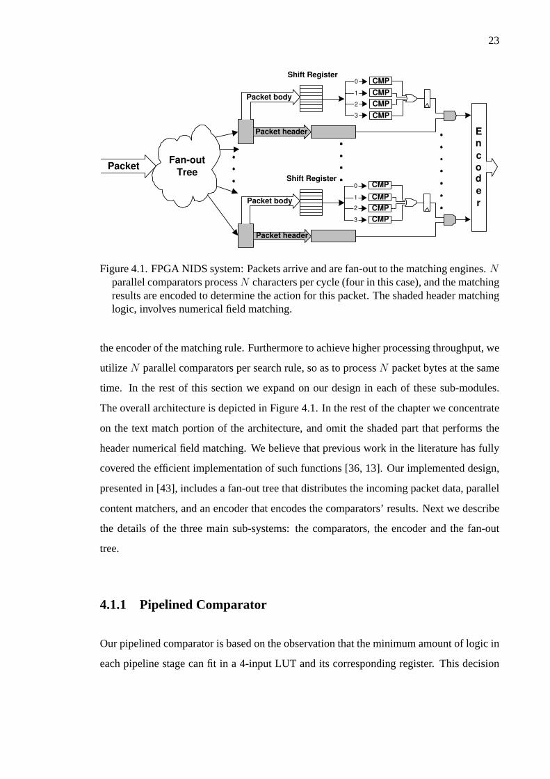
Figure 4.1. FPGA NIDS system: Packets arrive and are fan-out to the matching engines.Nparallel comparators processN characters per cycle (four in this case), and the matchingresults are encoded to determine the action for this packet. The shaded header matchinglogic, involves numerical field matching.
the encoder of the matching rule. Furthermore to achieve higher processing throughput, we
utilize N parallel comparators per search rule, so as to processN packet bytes at the same
time. In the rest of this section we expand on our design in each of these sub-modules.
The overall architecture is depicted in Figure 4.1. In the rest of the chapter we concentrate
on the text match portion of the architecture, and omit the shaded part that performs the
header numerical field matching. We believe that previous work in the literature has fully
covered the efficient implementation of such functions [36, 13]. Our implemented design,
presented in [43], includes a fan-out tree that distributes the incoming packet data, parallel
content matchers, and an encoder that encodes the comparators’ results. Next we describe
the details of the three main sub-systems: the comparators, the encoder and the fan-out
tree.
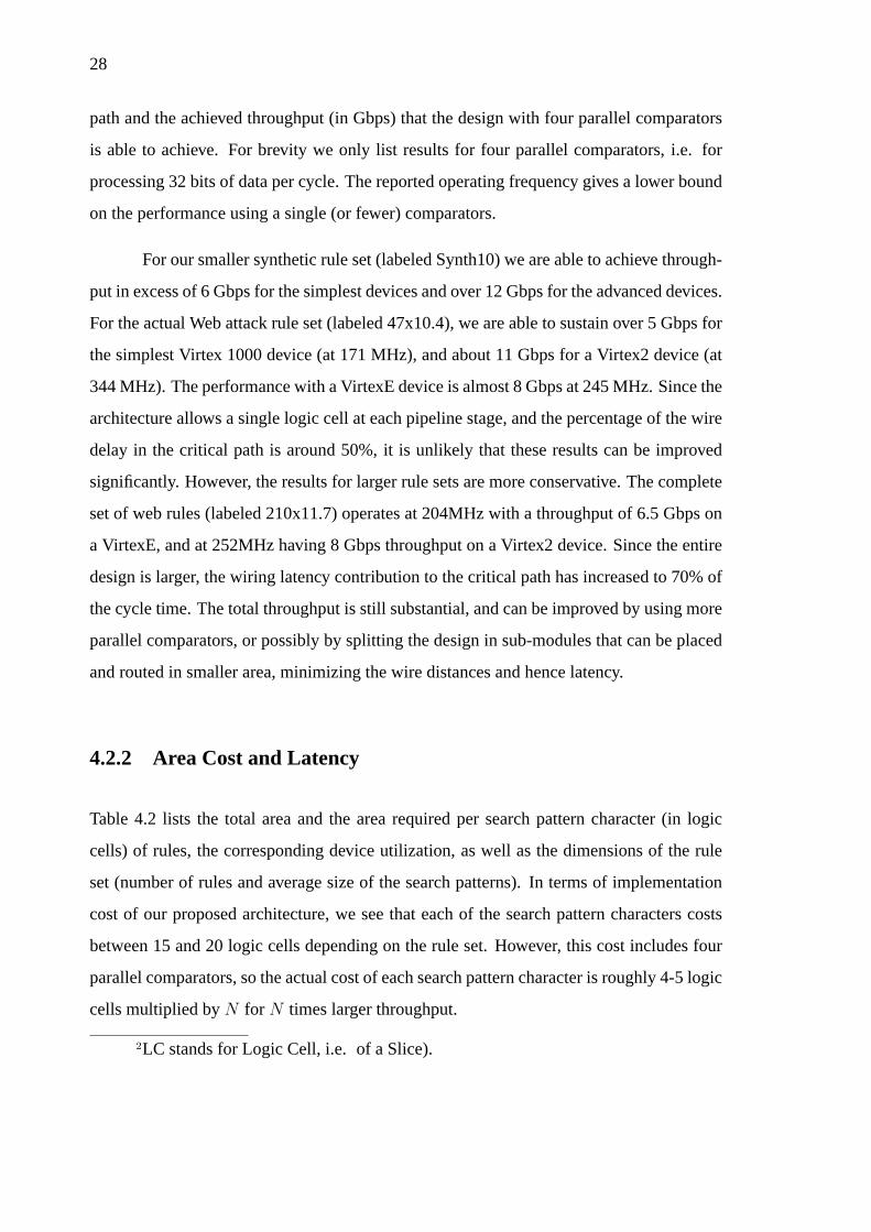
4.1.1 Pipelined Comparator
Our pipelined comparator is based on the observation that the minimum amount of logic in
each pipeline stage can fit in a 4-input LUT and its corresponding register. This decision
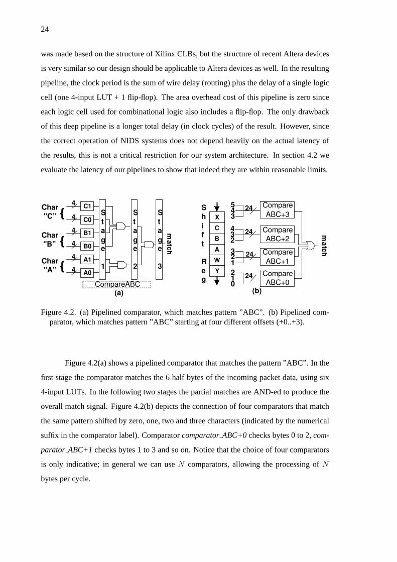
24
was made based on the structure of Xilinx CLBs, but the structure of recent Altera devices
is very similar so our design should be applicable to Altera devices as well. In the resulting
pipeline, the clock period is the sum of wire delay (routing) plus the delay of a single logic
cell (one 4-input LUT + 1 flip-flop). The area overhead cost of this pipeline is zero since
each logic cell used for combinational logic also includes a flip-flop. The only drawback
of this deep pipeline is a longer total delay (in clock cycles) of the result. However, since
the correct operation of NIDS systems does not depend heavily on the actual latency of
the results, this is not a critical restriction for our system architecture. In section 4.2 we
evaluate the latency of our pipelines to show that indeed they are within reasonable limits.
24 S
h
i
f
t
R
e g
3 4 5
24
2 3 4
24
1 2 3
24
0 1 2
m a
t c h
(b) (a)
A0
A1
B0
B1
C0
C1 4
4
4
4
4
4 m a
t c h
Char
"C”
Char
"A”
Char
"B”
S
t
a
g e
1
CompareABC
W
A
B
C
X
{
{
{
Compare
ABC+3
Y Compare
ABC+0
Compare
ABC+1
Compare
ABC+2
S
t
a
g e
2
S
t
a
g e
3
Figure 4.2. (a) Pipelined comparator, which matches pattern ”ABC”. (b) Pipelined com-parator, which matches pattern ”ABC” starting at four different offsets (+0..+3).
Figure 4.2(a) shows a pipelined comparator that matches the pattern ”ABC”. In the
first stage the comparator matches the 6 half bytes of the incoming packet data, using six
4-input LUTs. In the following two stages the partial matches are AND-ed to produce the
overall match signal. Figure 4.2(b) depicts the connection of four comparators that match
the same pattern shifted by zero, one, two and three characters (indicated by the numerical
suffix in the comparator label). ComparatorcomparatorABC+0checks bytes 0 to 2,com-
parator ABC+1checks bytes 1 to 3 and so on. Notice that the choice of four comparators
is only indicative; in general we can useN comparators, allowing the processing ofN
bytes per cycle.

25
4.1.2 Pipelined Encoder
After the individual matches have been determined, the matching rule has to be encoded
and reported to the rest of the system (most likely software). We use a hierarchical pipelined
encoder. In every stage, the combinational logic is described by at most 4-input, 1-output
logic functions, which is permitted in our architecture.
The described encoder assumes that at most one match will occur in order to operate
correctly (i.e. it is not a priority encoder). While in general multiple matches can occur
in a single cycle, in practice we can determine by examining the search strings whether
this situation can occur in practice. If all the search patterns have distinct suffixes, then
we are ensured that we will not have multiple matches in a single cycle. However, this
guarantee becomes more difficult as we increase the number of concurrent comparators. A
pipelined version of a priority encoder, which will be able to correctly handle any search
string combination, is part of this thesis future work (section 7.2).
4.1.3 Packet data Fan-out
The fan-out delay is major slow-down factor that designers must take into account. While
it involves no logic, signals must traverse long distances and potentially suffer significant
latencies. To address this bottleneck we created a register tree to ”feed” the comparators
with the incoming data. The leaves of this tree are the shift registers that feed the com-
parators, while the intermediate nodes of the tree serve as buffers and pipeline registers at
the same time. To determine the best fan-out factor for the tree, we experimented with the
Xilinx tools, and we determined that for best results, the optimal fan-out factor changes
from level to level. In our design we used small fan-out for the first tree levels and increase
the fan-out in the later levels of the tree up to 15 in the last tree level. Intuitively, that is
because the first levels of the tree feed large blocks and the distance between the fed nodes
is much larger than in last levels. We also experimented and found that the optimal fan-out
from the shift-registers is 16 (15 wires to feed comparators and 1 to the next register of
26
shift register).
4.1.4 VHDL Generator
Deriving a VHDL representation of a string matching module starting from a Snort rule
is very tedious; to handle tens or hundreds of rules is not only tedious but extremely error
prone. Since the architecture of our system is very regular, we developed a C program
that automatically generates the desired VHDL representation directly from Snort pattern
matching expressions, and we used a simple PERL script to extract all the patterns from a
Snort rule file.
4.2 Evaluation Results
The quality of an FPGA-based intrusion detection system can be measured mainly using
performance and area metrics. We measure performance in terms of operating frequency
(to indicate the efficiency of our fine grain pipelining) and total throughput that can be
serviced, and area in terms of total area needed, as well as area cost per search pattern
character.
We used four sets of rules to evaluate our proposed architecture. The first two are ar-
tificial sets that cannot be optimized (i.e. at every position all search characters are distinct),
and contain 10 rules matching 10 characters each (Synth10), and 16 rules of 16 characters
each (Synth16). We also used the ”web-attacks.rules” from the Snort distribution, a set of
47 rules to show performance and cost for a medium size rule set, and we used the entire
set of web rules (a total of 210 rules) to test the scalability of our approach for larger rule
sets. The average search pattern length for these sets was 10.4 and 11.7 characters for the
Web-attack and all the Web rules respectively.
We synthesized each of these rule sets using the Xilinx tools (ISE 4.2i) for several
devices (the -N suffix indicates speed grade): Virtex 1000-6, VirtexE 1000-8, Virtex2 1000-
27
5, VirtexE 2600-8 and Virtex2 6000-5. The structure of these devices is similar and the area
cost of our design is expected (and turns out) to be almost identical for all devices, with the
main difference being the performance.
Rule Set Synth10 Synth16 Web attacks Web-all
# Patterns (rules) 10 16 47 210
Av. Pattern Size 10 16 10.4 11.7
(characters)
Virtex MHz 193 193 171
1000 Wire delay 56.7% 45.2% 61.9%
-6 Gbps 6.176 6.176 5.472
VirtexE MHz 272 254 245
1000 Wire delay 54.6% 57.5% 49.8%
-8 Gbps 8.707 8.144 7.840
Virtex2 MHz 396 383 344
1000 Wire delay 37.4% 54.1% 58.7%
-5 Gbps 12.672 12.256 11.008
VirtexE MHz 204
2600 Wire delay 70.2%
-8 Gbps 6.528
Virtex2 MHz 252
6000 Wire delay 69.7%
-5 Gbps 8.064
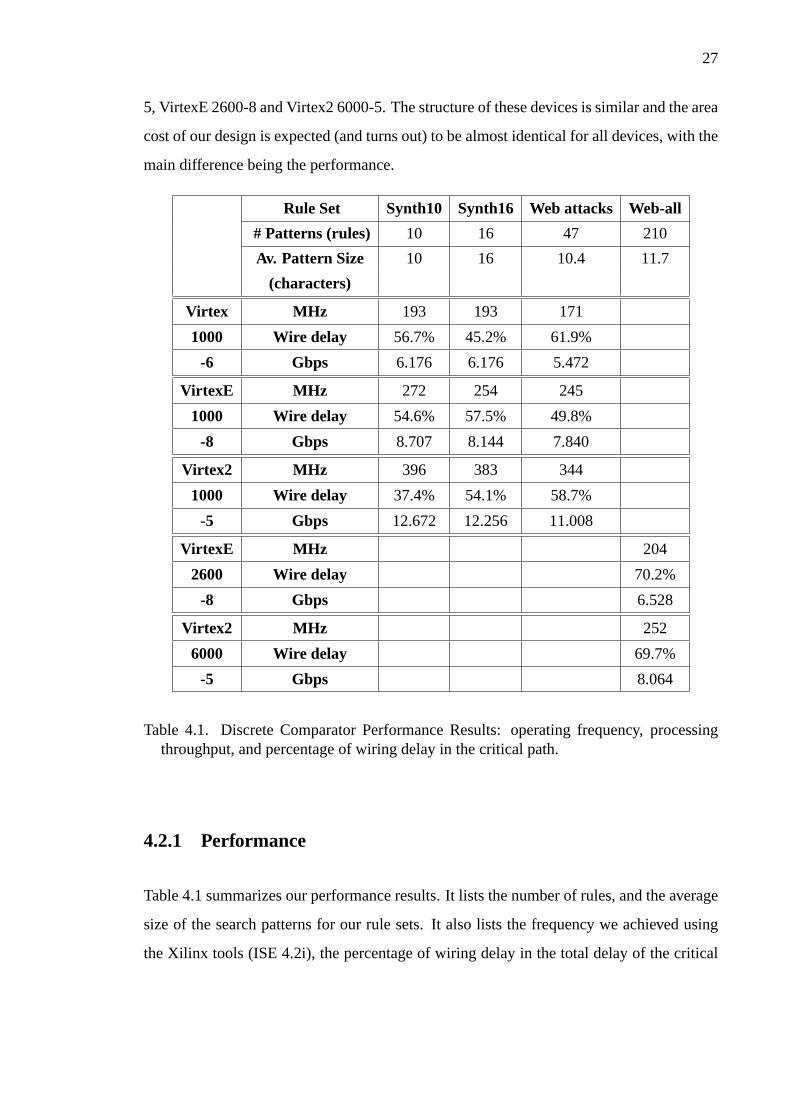
Table 4.1. Discrete Comparator Performance Results: operating frequency, processingthroughput, and percentage of wiring delay in the critical path.
4.2.1 Performance
Table 4.1 summarizes our performance results. It lists the number of rules, and the average
size of the search patterns for our rule sets. It also lists the frequency we achieved using
the Xilinx tools (ISE 4.2i), the percentage of wiring delay in the total delay of the critical
28
path and the achieved throughput (in Gbps) that the design with four parallel comparators
is able to achieve. For brevity we only list results for four parallel comparators, i.e. for
processing 32 bits of data per cycle. The reported operating frequency gives a lower bound
on the performance using a single (or fewer) comparators.
For our smaller synthetic rule set (labeled Synth10) we are able to achieve through-
put in excess of 6 Gbps for the simplest devices and over 12 Gbps for the advanced devices.
For the actual Web attack rule set (labeled 47x10.4), we are able to sustain over 5 Gbps for
the simplest Virtex 1000 device (at 171 MHz), and about 11 Gbps for a Virtex2 device (at
344 MHz). The performance with a VirtexE device is almost 8 Gbps at 245 MHz. Since the
architecture allows a single logic cell at each pipeline stage, and the percentage of the wire
delay in the critical path is around 50%, it is unlikely that these results can be improved
significantly. However, the results for larger rule sets are more conservative. The complete
set of web rules (labeled 210x11.7) operates at 204MHz with a throughput of 6.5 Gbps on
a VirtexE, and at 252MHz having 8 Gbps throughput on a Virtex2 device. Since the entire
design is larger, the wiring latency contribution to the critical path has increased to 70% of
the cycle time. The total throughput is still substantial, and can be improved by using more
parallel comparators, or possibly by splitting the design in sub-modules that can be placed
and routed in smaller area, minimizing the wire distances and hence latency.
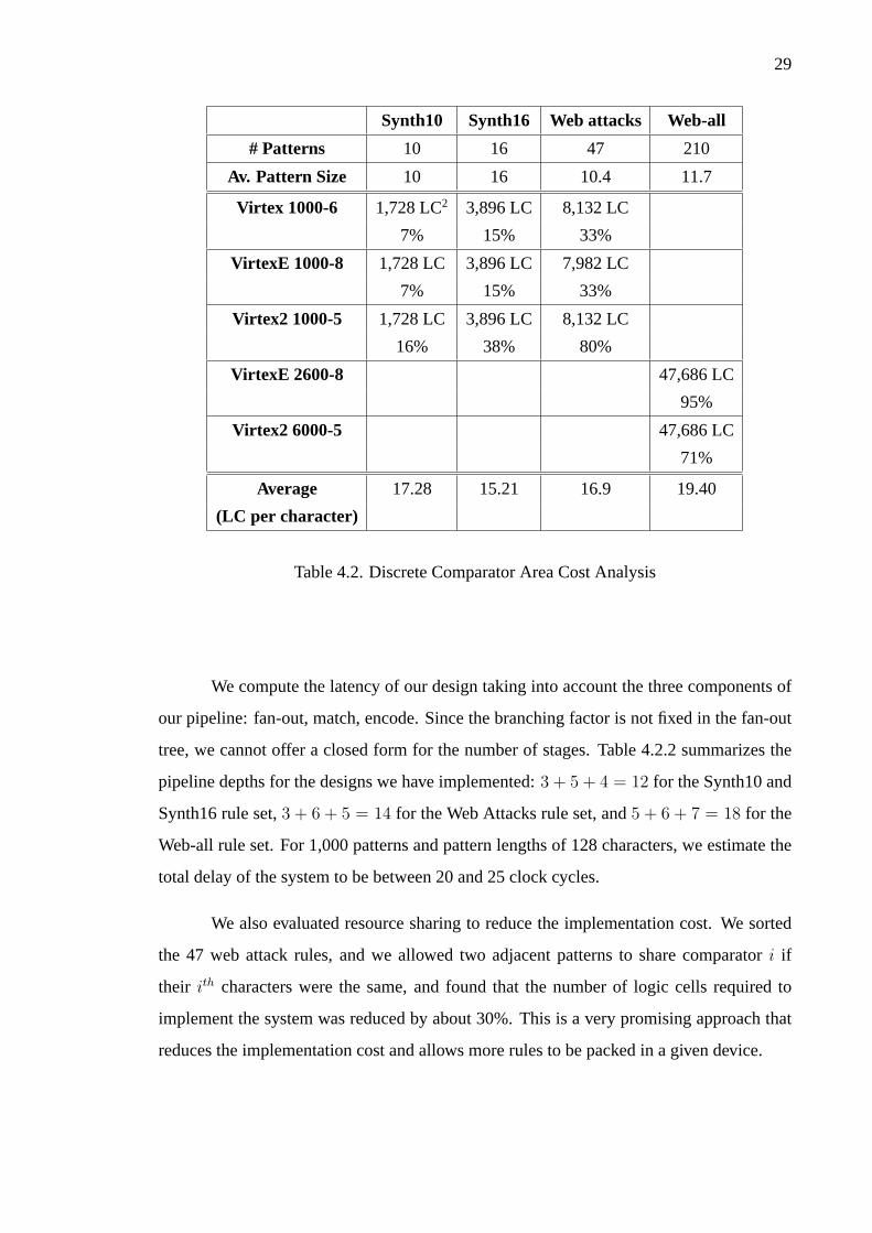
4.2.2 Area Cost and Latency
Table 4.2 lists the total area and the area required per search pattern character (in logic
cells) of rules, the corresponding device utilization, as well as the dimensions of the rule
set (number of rules and average size of the search patterns). In terms of implementation
cost of our proposed architecture, we see that each of the search pattern characters costs
between 15 and 20 logic cells depending on the rule set. However, this cost includes four
parallel comparators, so the actual cost of each search pattern character is roughly 4-5 logic
cells multiplied byN for N times larger throughput.
2LC stands for Logic Cell, i.e. of a Slice).
29
Synth10 Synth16 Web attacks Web-all
# Patterns 10 16 47 210
Av. Pattern Size 10 16 10.4 11.7
Virtex 1000-6 1,728 LC2 3,896 LC 8,132 LC
7% 15% 33%
VirtexE 1000-8 1,728 LC 3,896 LC 7,982 LC
7% 15% 33%
Virtex2 1000-5 1,728 LC 3,896 LC 8,132 LC
16% 38% 80%
VirtexE 2600-8 47,686 LC
95%
Virtex2 6000-5 47,686 LC
71%
Average 17.28 15.21 16.9 19.40
(LC per character)
Table 4.2. Discrete Comparator Area Cost Analysis
We compute the latency of our design taking into account the three components of
our pipeline: fan-out, match, encode. Since the branching factor is not fixed in the fan-out
tree, we cannot offer a closed form for the number of stages. Table 4.2.2 summarizes the
pipeline depths for the designs we have implemented:3 + 5 + 4 = 12 for the Synth10 and
Synth16 rule set,3 + 6 + 5 = 14 for the Web Attacks rule set, and5 + 6 + 7 = 18 for the
Web-all rule set. For 1,000 patterns and pattern lengths of 128 characters, we estimate the
total delay of the system to be between 20 and 25 clock cycles.
We also evaluated resource sharing to reduce the implementation cost. We sorted
the 47 web attack rules, and we allowed two adjacent patterns to share comparatori if
their ith characters were the same, and found that the number of logic cells required to
implement the system was reduced by about 30%. This is a very promising approach that
reduces the implementation cost and allows more rules to be packed in a given device.
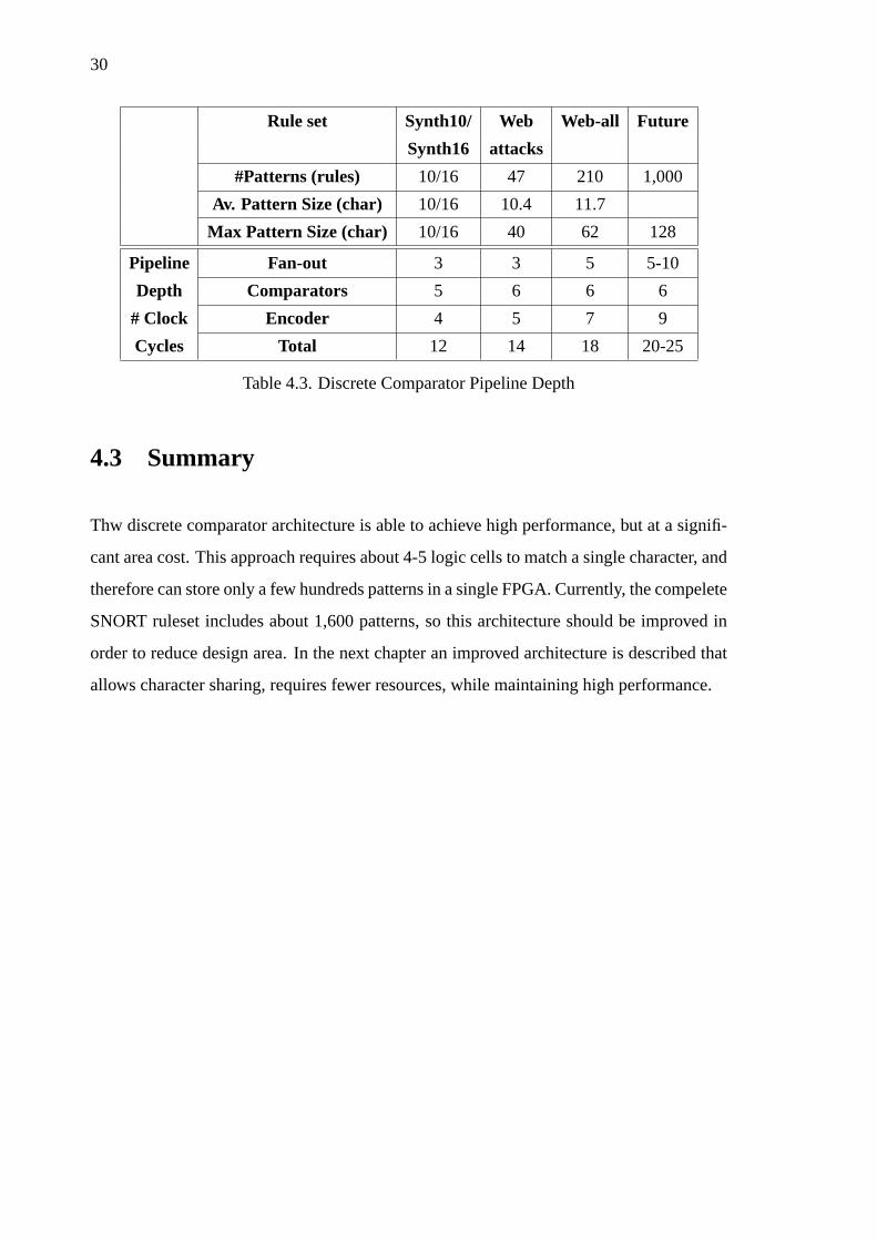
30
Rule set Synth10/ Web Web-all Future
Synth16 attacks
#Patterns (rules) 10/16 47 210 1,000
Av. Pattern Size (char) 10/16 10.4 11.7
Max Pattern Size (char) 10/16 40 62 128
Pipeline Fan-out 3 3 5 5-10
Depth Comparators 5 6 6 6
# Clock Encoder 4 5 7 9
Cycles Total 12 14 18 20-25
Table 4.3. Discrete Comparator Pipeline Depth
4.3 Summary
Thw discrete comparator architecture is able to achieve high performance, but at a signifi-
cant area cost. This approach requires about 4-5 logic cells to match a single character, and
therefore can store only a few hundreds patterns in a single FPGA. Currently, the compelete
SNORT ruleset includes about 1,600 patterns, so this architecture should be improved in
order to reduce design area. In the next chapter an improved architecture is described that
allows character sharing, requires fewer resources, while maintaining high performance.

31
CHAPTER 5
DECODED CAMS
The discrete comparator architecture, presented in the previous chapter, has high area cost.
This chapter presents a better architecture, with much lower area cost and similar perfor-
mance. Techniques such as partitioning, pre-decoding, and wide data distribution buses,
are proposed in order to improve this architecture. Finally, performance and area results
are presented, and this architecture is compared with discrete comparator approach.
5.1 Decoded CAM Architecture
The overall organization of a pattern matching system is simple: a single input supplies the
input stream of characters, and the output is an indication that a match did occur, plus the
identifier of the matching rule. The details of this system (e.g. the encoder of matching
signals, etc) are straightforward, we concentrate on the actual pattern matching block.
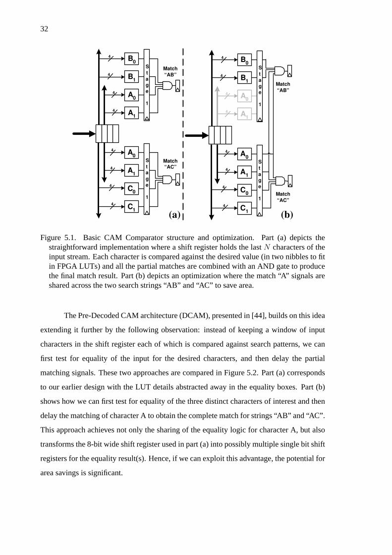
In chapter 4, we assumed the simple organization depicted in Figure 5.1(a). The
input stream is inserted in a shift register, and the individual entries are fanned out to
the pattern comparators. Therefore, in order to search for strings “AB” and “AC”, we
have two comparators fed from the first two position of the shift register. Figure 5.1(a)
reflects the FPGA implementation where each 8-bit comparator is broken down to two 4-bit
comparators, each of which fits in one LUT. This implementation is simple and regular, and
with proper use of pipelining it can achieve very high operating frequencies. Its drawback
is the high area cost. To remedy this cost, in our previous work we had suggestedsharing
the character comparators for strings with “similarities”. This is shown in Figure 5.1(b)
where the result of a single comparator for character A is shared between the two search
strings “AB” and “AC”. Our preliminary results at the time indicated an area improvement
of at least 30%.
32
A 1
A 0
B 1
B 0
S
t
a g
e
1
4
4
4
4
4
4
4
4
C 1
C 0
A 1
A 0
S
t a
g
e
1
Match
“AB”
Match “AC”
4
4
4
4
C 1
C 0
A 1
A 0
S
t
a g
e
1
Match
“AB”
Match
“AC”
(a) (b)
A 1
A 0
B 1
B 0
S
t
a g
e
1
4
4
4
4
Figure 5.1. Basic CAM Comparator structure and optimization. Part (a) depicts thestraightforward implementation where a shift register holds the lastN characters of theinput stream. Each character is compared against the desired value (in two nibbles to fitin FPGA LUTs) and all the partial matches are combined with an AND gate to producethe final match result. Part (b) depicts an optimization where the match “A” signals areshared across the two search strings “AB” and “AC” to save area.
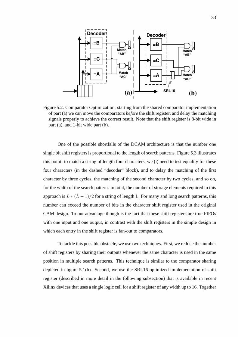
The Pre-Decoded CAM architecture (DCAM), presented in [44], builds on this idea
extending it further by the following observation: instead of keeping a window of input
characters in the shift register each of which is compared against search patterns, we can
first test for equality of the input for the desired characters, and then delay the partial
matching signals. These two approaches are compared in Figure 5.2. Part (a) corresponds
to our earlier design with the LUT details abstracted away in the equality boxes. Part (b)
shows how we can first test for equality of the three distinct characters of interest and then
delay the matching of character A to obtain the complete match for strings “AB” and “AC”.
This approach achieves not only the sharing of the equality logic for character A, but also
transforms the 8-bit wide shift register used in part (a) into possibly multiple single bit shift
registers for the equality result(s). Hence, if we can exploit this advantage, the potential for
area savings is significant.
33
=C
=A Match
“AC”
Match
“AB”
=B
=C
=A Match
“AC”
Match
“AB”
(a) (b)
=B
SRL16
Decoder Decoder
Figure 5.2. Comparator Optimization: starting from the shared comparator implementationof part (a) we can move the comparatorsbeforethe shift register, and delay the matchingsignals properly to achieve the correct result. Note that the shift register is 8-bit wide inpart (a), and 1-bit wide part (b).
One of the possible shortfalls of the DCAM architecture is that the number one
single bit shift registers is proportional to the length of search patterns. Figure 5.3 illustrates
this point: to match a string of length four characters, we (i) need to test equality for these
four characters (in the dashed “decoder” block), and to delay the matching of the first
character by three cycles, the matching of the second character by two cycles, and so on,
for the width of the search pattern. In total, the number of storage elements required in this
approach isL ∗ (L− 1)/2 for a string of length L. For many and long search patterns, this
number can exceed the number of bits in the character shift register used in the original
CAM design. To our advantage though is the fact that these shift registers are true FIFOs
with one input and one output, in contrast with the shift registers in the simple design in
which each entry in the shift register is fan-out to comparators.
To tackle this possible obstacle, we use two techniques. First, we reduce the number
of shift registers by sharing their outputs whenever the same character is used in the same
position in multiple search patterns. This technique is similar to the comparator sharing
depicted in figure 5.1(b). Second, we use the SRL16 optimized implementation of shift
register (described in more detail in the following subsection) that is available in recent
Xilinx devices that uses a single logic cell for a shift register of any width up to 16. Together

34
Decoder
=C
=B
=A
Match
“ABCD”
=D
SRL16
8
8
8
8
8
Incoming
Packets
Figure 5.3. Details of Pre-decoded CAM matching: four comparators provide the equalitysignals for characters A, B, C, and D. To match the string “ABCD” we have to rememberthe matching of character A 3 cycles earlier, the matching of B two cycles earlier, etc,until the final character is matched in the current cycle. This is achieved with the shiftregisters of width 3, 2, ... at the proper match lines.
these two optimizations lead to significant area savings as we will show in the evaluation
section. In the following subsections we describe the techniques we used to achieve an
efficient implementation of the DCAM architecture.
5.1.1 Xilinx SRL16 shift register
The Xilinx SRL16 cell is a shift register with a programmable width up to 16 bits. It uses
the 16×1 storage space that implements the Lookup Table, and as a result it is implemented
with a single Logic Cell. The four inputs that usually are the LUT’s inputs are used to
determine the width of the shift register. While the SRL16 provides synchronous output, for
timing reasons it is beneficial to add an additional flip-flop to its output. This configuration
provides a better timing solution and simplifies the design [47]. In addition it allows a
single logic cell to implement a shift register with width of up to 17 bits. Figure 5.4 shows
the detailed block diagram of a logic cell configured as a SRL16 shift register.
In our design, we use one SRL16 cell at the output of each equality test (i.e. for
each distinct character) and for each location (offset) where this character appears in a

35
CLK
CE
SRL16
(Write Enable)
Address
D Q D Q
Flip-Flop
Q15
Synchronous
Output
Figure 5.4. Xilinx Logic Cell SRL16 structure. Fully synchronous Shift Register.
search pattern. However, we share the output of the SRL16 cells for search pattern charac-
ters that appear in the same position in multiple search strings. To avoid fan-out problems
we replicate SRL16 cells so that the fanout does not exceed 16. This is based on an ex-
perimental evaluation we performed on Xilinx devices that showed that when the fanout
exceeds 16 the operating frequency drops significantly.
5.1.2 Techniques to Increase Performance
In order to achieve better performance we used techniques to improve the operating speed,
as well as the throughput of our DCAM implementation. To achieve high operating fre-
quency, we use extensive fine grain pipeline in a manner similar to our earlier work. In
fact, each of our pipeline stages consists of a single processing LUT and a pipeline register
in its output. In this way the operating frequency is limited by the latency of a single logic
cell and the interconnection wires. To keep interconnection wires short, we addressed the
long data distribution wires that usually have large fan-out by providing a pipelined fan-out
tree. More details on these two techniques can be found in [43].
As alluded earlier, to increase the processing throughput of a DCAM we can use
parallelism. Similar to our previous work we can widen the distribution paths by a factor
of P providingP copies of comparators(decoders) and the corresponding matching gates.
Figure 5.5 illustrates this point forP = 2. The single string ABC is searched for starting
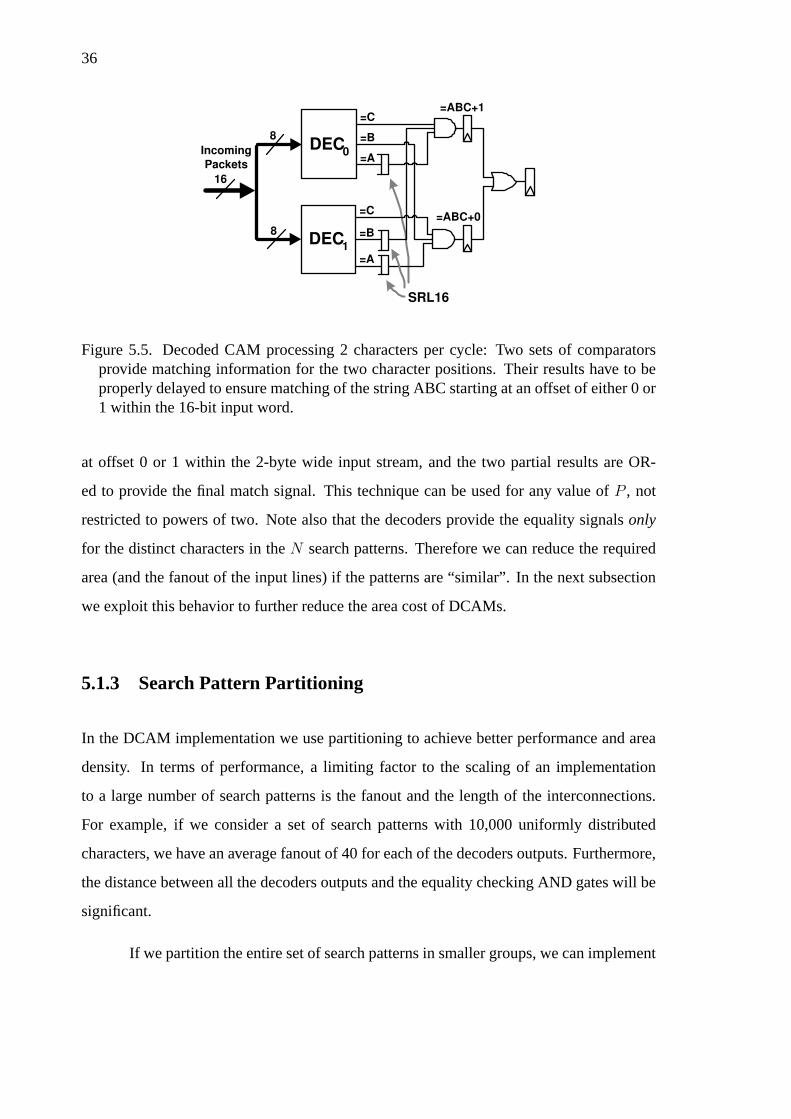
36
DEC 1
=A
=ABC+0
=ABC+1
=C
=B
DEC 0
=A
=C
=B 8
8
16
SRL16
Incoming
Packets
Figure 5.5. Decoded CAM processing 2 characters per cycle: Two sets of comparatorsprovide matching information for the two character positions. Their results have to beproperly delayed to ensure matching of the string ABC starting at an offset of either 0 or1 within the 16-bit input word.
at offset 0 or 1 within the 2-byte wide input stream, and the two partial results are OR-
ed to provide the final match signal. This technique can be used for any value ofP , not
restricted to powers of two. Note also that the decoders provide the equality signalsonly
for the distinct characters in theN search patterns. Therefore we can reduce the required
area (and the fanout of the input lines) if the patterns are “similar”. In the next subsection
we exploit this behavior to further reduce the area cost of DCAMs.
5.1.3 Search Pattern Partitioning
In the DCAM implementation we use partitioning to achieve better performance and area
density. In terms of performance, a limiting factor to the scaling of an implementation
to a large number of search patterns is the fanout and the length of the interconnections.
For example, if we consider a set of search patterns with 10,000 uniformly distributed
characters, we have an average fanout of 40 for each of the decoders outputs. Furthermore,
the distance between all the decoders outputs and the equality checking AND gates will be
significant.
If we partition the entire set of search patterns in smaller groups, we can implement
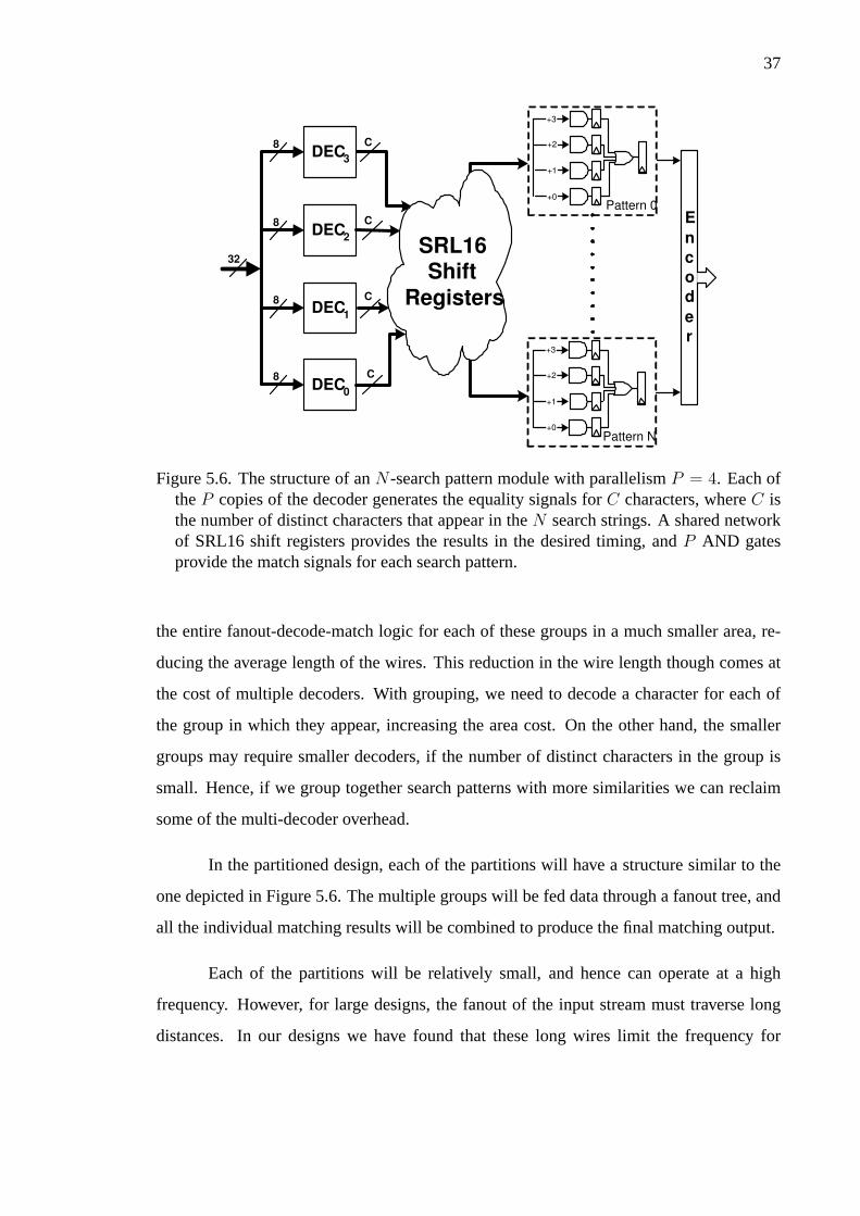
37
E
n
c
o
d
e
r
32
DEC 0
8
DEC 1
8
DEC 2
8
8 C DEC
3
C
C
C
SRL16 Shift
Registers
Pattern 0
+3
+2
+0
+1
Pattern N
+3
+2
+0
+1
Figure 5.6. The structure of anN -search pattern module with parallelismP = 4. Each oftheP copies of the decoder generates the equality signals forC characters, whereC isthe number of distinct characters that appear in theN search strings. A shared networkof SRL16 shift registers provides the results in the desired timing, andP AND gatesprovide the match signals for each search pattern.
the entire fanout-decode-match logic for each of these groups in a much smaller area, re-
ducing the average length of the wires. This reduction in the wire length though comes at
the cost of multiple decoders. With grouping, we need to decode a character for each of
the group in which they appear, increasing the area cost. On the other hand, the smaller
groups may require smaller decoders, if the number of distinct characters in the group is
small. Hence, if we group together search patterns with more similarities we can reclaim
some of the multi-decoder overhead.
In the partitioned design, each of the partitions will have a structure similar to the
one depicted in Figure 5.6. The multiple groups will be fed data through a fanout tree, and
all the individual matching results will be combined to produce the final matching output.
Each of the partitions will be relatively small, and hence can operate at a high
frequency. However, for large designs, the fanout of the input stream must traverse long
distances. In our designs we have found that these long wires limit the frequency for
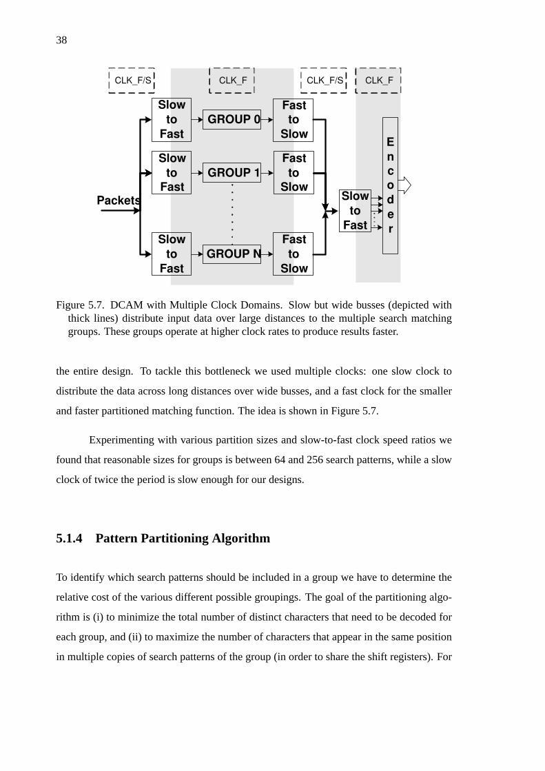
38
E
n
c
o
d
e
r
GROUP 0
Slow
to
Fast
Slow
to
Fast
Packets
GROUP 1
GROUP N
Fast
to
Slow
Slow
to
Fast
Slow
to
Fast
Fast
to
Slow
Fast
to
Slow
CLK_F/S CLK_F CLK_F CLK_F/S
Figure 5.7. DCAM with Multiple Clock Domains. Slow but wide busses (depicted withthick lines) distribute input data over large distances to the multiple search matchinggroups. These groups operate at higher clock rates to produce results faster.
the entire design. To tackle this bottleneck we used multiple clocks: one slow clock to
distribute the data across long distances over wide busses, and a fast clock for the smaller
and faster partitioned matching function. The idea is shown in Figure 5.7.
Experimenting with various partition sizes and slow-to-fast clock speed ratios we
found that reasonable sizes for groups is between 64 and 256 search patterns, while a slow
clock of twice the period is slow enough for our designs.
5.1.4 Pattern Partitioning Algorithm
To identify which search patterns should be included in a group we have to determine the
relative cost of the various different possible groupings. The goal of the partitioning algo-
rithm is (i) to minimize the total number of distinct characters that need to be decoded for
each group, and (ii) to maximize the number of characters that appear in the same position
in multiple copies of search patterns of the group (in order to share the shift registers). For
39
this work we have implemented a simple, greedy algorithm that partitions iteratively the
set of search strings according to the following steps:
1. First we create an array with one entry for each search pattern. Each array entry
contains the set of distinct characters in the search string.
2. Starting with a number of empty partitions or groups, we first perform a step of initial
assignment of search patterns to obtain a “seed” pattern in each group of the different
groups.
3. Then we use an iterative method: for each group we select an unassigned search
pattern so that the cost of adding it to the group is the least among the unassigned
patterns. The cost is computed by finding the set difference between the set of char-
acters used already by the group and the set of characters in the search pattern under
consideration. We iterate among all groups and all search patterns until all the pat-
terns have been assigned to a group.
Our algorithm implements a simple heuristic and does not guarantee an optimal
partitioning of the search patterns. However, we have compared it with a straightforward
approach of just sorting the search patterns, and we found that using the group identified
by our algorithm the area cost was about 5% smaller and 5% faster than the one using
partitioning based on sorted search patterns. Our algorithm is more efficient in minimizing
the number of shift registers requiring 9% fewer shift registers as compared to the sorting
the search patterns. For the entire SNORT rule set and using 24 groups, our algorithm
produced groups that contain an average of 54 distinct search characters each. Therefore
each of the decoders is significantly smaller that a full 8-to-256 decoder.
5.2 Evaluation
We evaluate the efficiency of our DCAM architecture and implementation using two main
metrics: performance in terms of operating frequency and processing throughput, and area
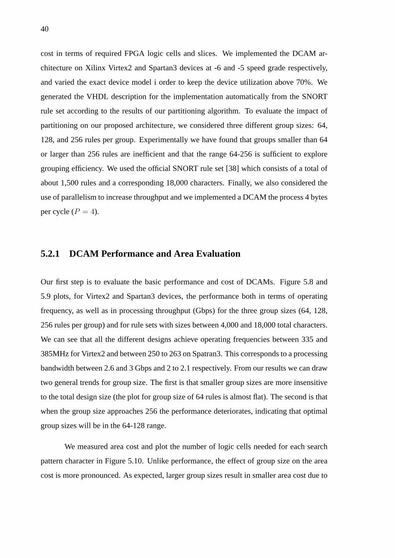
40
cost in terms of required FPGA logic cells and slices. We implemented the DCAM ar-
chitecture on Xilinx Virtex2 and Spartan3 devices at -6 and -5 speed grade respectively,
and varied the exact device model i order to keep the device utilization above 70%. We
generated the VHDL description for the implementation automatically from the SNORT
rule set according to the results of our partitioning algorithm. To evaluate the impact of
partitioning on our proposed architecture, we considered three different group sizes: 64,
128, and 256 rules per group. Experimentally we have found that groups smaller than 64
or larger than 256 rules are inefficient and that the range 64-256 is sufficient to explore
grouping efficiency. We used the official SNORT rule set [38] which consists of a total of
about 1,500 rules and a corresponding 18,000 characters. Finally, we also considered the
use of parallelism to increase throughput and we implemented a DCAM the process 4 bytes
per cycle (P = 4).
5.2.1 DCAM Performance and Area Evaluation
Our first step is to evaluate the basic performance and cost of DCAMs. Figure 5.8 and
5.9 plots, for Virtex2 and Spartan3 devices, the performance both in terms of operating
frequency, as well as in processing throughput (Gbps) for the three group sizes (64, 128,
256 rules per group) and for rule sets with sizes between 4,000 and 18,000 total characters.
We can see that all the different designs achieve operating frequencies between 335 and
385MHz for Virtex2 and between 250 to 263 on Spatran3. This corresponds to a processing
bandwidth between 2.6 and 3 Gbps and 2 to 2.1 respectively. From our results we can draw
two general trends for group size. The first is that smaller group sizes are more insensitive
to the total design size (the plot for group size of 64 rules is almost flat). The second is that
when the group size approaches 256 the performance deteriorates, indicating that optimal
group sizes will be in the 64-128 range.
We measured area cost and plot the number of logic cells needed for each search
pattern character in Figure 5.10. Unlike performance, the effect of group size on the area
cost is more pronounced. As expected, larger group sizes result in smaller area cost due to
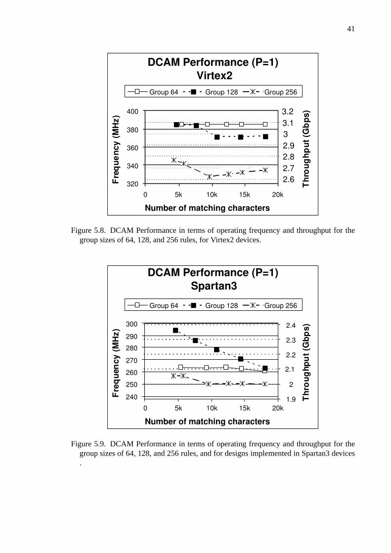
41
DCAM Performance (P=1)
Virtex2
320
340
360
380
400
0 5k 10k 15k 20k
Number of matching characters
F r e
q u
e n
c y (
M H
z )
Group 64 Group 128 Group 256
2.6
2.7
2.8
2.9
3
3.1
3.2
T h
r o u
g h
p u
t ( G
b p
s )
Figure 5.8. DCAM Performance in terms of operating frequency and throughput for thegroup sizes of 64, 128, and 256 rules, for Virtex2 devices.
DCAM Performance (P=1)
Spartan3
0 5k 10k 15k 20k
Number of matching characters
F r e
q u
e n c
y (
M H
z )
Group 64 Group 128 Group 256 T
h r o
u g
h p u
t ( G
b p
s )
1.9
2
2.1
2.2
2.3
2.4
240
250
260
270
280
290
300
Figure 5.9. DCAM Performance in terms of operating frequency and throughput for thegroup sizes of 64, 128, and 256 rules, and for designs implemented in Spartan3 devices.
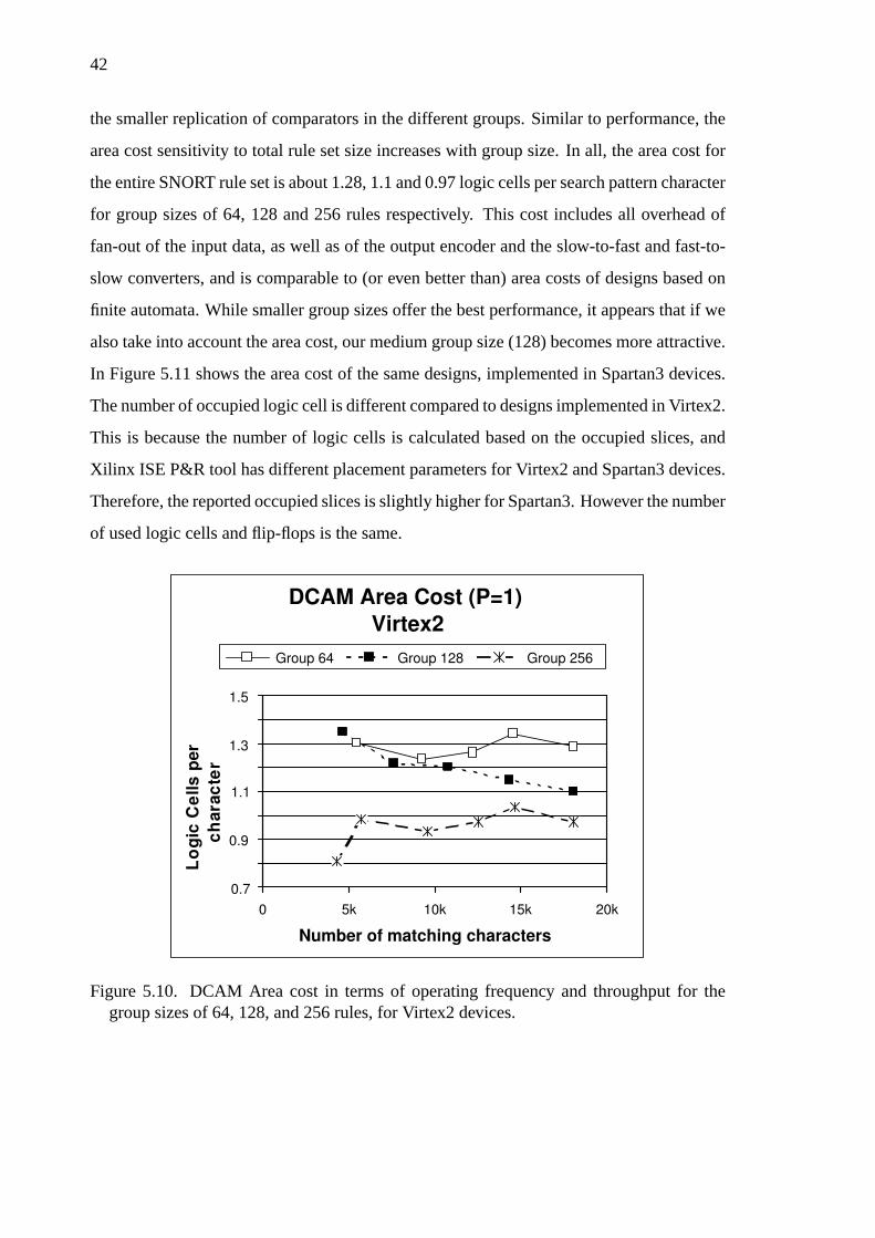
42
the smaller replication of comparators in the different groups. Similar to performance, the
area cost sensitivity to total rule set size increases with group size. In all, the area cost for
the entire SNORT rule set is about 1.28, 1.1 and 0.97 logic cells per search pattern character
for group sizes of 64, 128 and 256 rules respectively. This cost includes all overhead of
fan-out of the input data, as well as of the output encoder and the slow-to-fast and fast-to-
slow converters, and is comparable to (or even better than) area costs of designs based on
finite automata. While smaller group sizes offer the best performance, it appears that if we
also take into account the area cost, our medium group size (128) becomes more attractive.
In Figure 5.11 shows the area cost of the same designs, implemented in Spartan3 devices.
The number of occupied logic cell is different compared to designs implemented in Virtex2.
This is because the number of logic cells is calculated based on the occupied slices, and
Xilinx ISE P&R tool has different placement parameters for Virtex2 and Spartan3 devices.
Therefore, the reported occupied slices is slightly higher for Spartan3. However the number
of used logic cells and flip-flops is the same.
DCAM Area Cost (P=1)
Virtex2
0.7
0.9
1.1
1.3
1.5
0 5k 10k 15k 20k
Number of matching characters
L o
g i c
C e
l l s p
e r
c h
a r a
c t e
r
Group 64 Group 128 Group 256
Figure 5.10. DCAM Area cost in terms of operating frequency and throughput for thegroup sizes of 64, 128, and 256 rules, for Virtex2 devices.
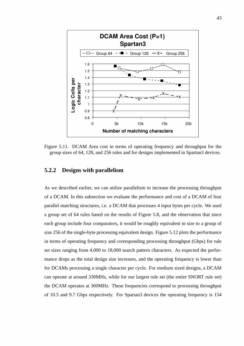
43
0 5k 10k 15k 20k
Number of matching characters
L o
g i c
C e
l l s p
e r
c h
a r a
c t e
r
Group 64 Group 128 Group 256
0.8
0.9
1
1.1
1.2
1.3
1.4
1.5
1.6
DCAM Area Cost (P=1)
Spartan3
Figure 5.11. DCAM Area cost in terms of operating frequency and throughput for thegroup sizes of 64, 128, and 256 rules and for designs implemented in Spartan3 devices.
5.2.2 Designs with parallelism
As we described earlier, we can utilize parallelism to increase the processing throughput
of a DCAM. In this subsection we evaluate the performance and cost of a DCAM of four
parallel matching structures, i.e. a DCAM that processes 4 input bytes per cycle. We used
a group set of 64 rules based on the results of Figure 5.8, and the observation that since
each group include four comparators, it would be roughly equivalent in size to a group of
size 256 of the single-byte processing equivalent design. Figure 5.12 plots the performance
in terms of operating frequency and corresponding processing throughput (Gbps) for rule
set sizes ranging from 4,000 to 18,000 search pattern characters. As expected the perfor-
mance drops as the total design size increases, and the operating frequency is lower than
for DCAMs processing a single character per cycle. For medium sized designs, a DCAM
can operate at around 330MHz, while for our largest rule set (the entire SNORT rule set)
the DCAM operates at 300MHz. These frequencies correspond to processing throughput
of 10.5 and 9.7 Gbps respectively. For Spartan3 devices the operating frequency is 154
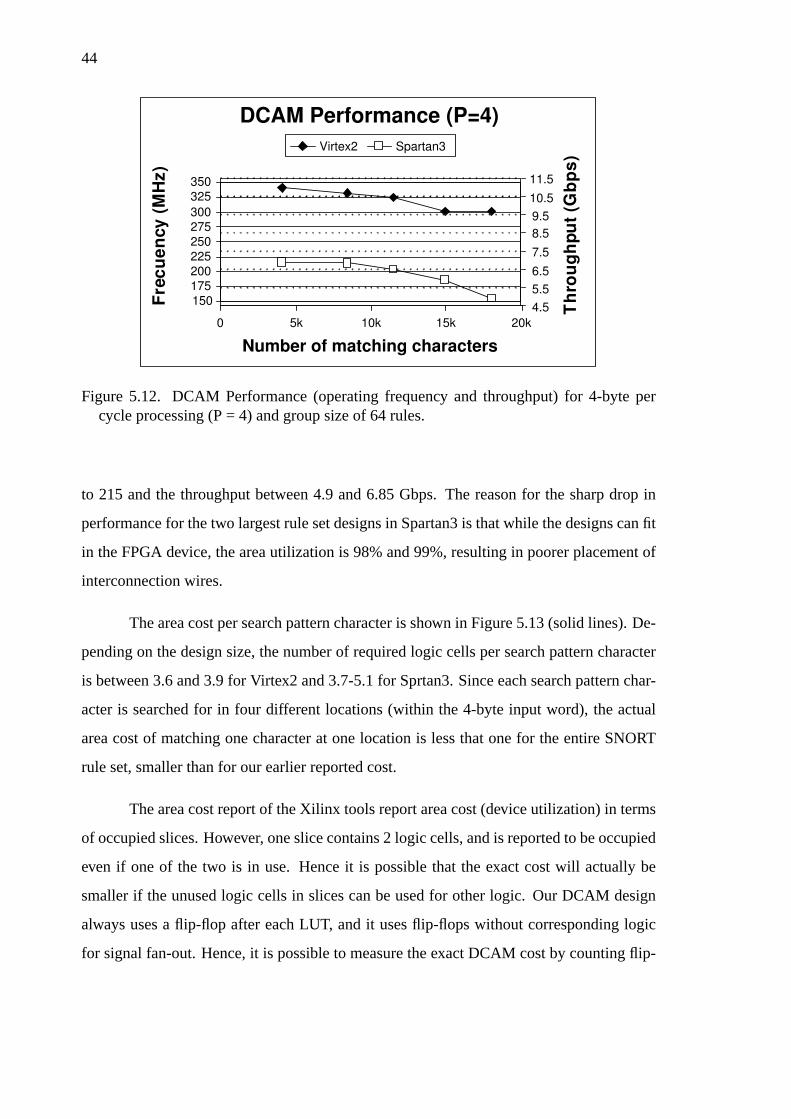
44
DCAM Performance (P=4)
0 5k 10k 15k 20k
Number of matching characters
F r e
c u
e n
c y (
M H
z )
T h
r o u
g h
p u
t ( G
b p
s )
4.5
5.5
6.5
7.5
8.5
9.5
10.5
11.5
Virtex2 Spartan3
150
175
200
225
250
275
300
325
350
Figure 5.12. DCAM Performance (operating frequency and throughput) for 4-byte percycle processing (P = 4) and group size of 64 rules.
to 215 and the throughput between 4.9 and 6.85 Gbps. The reason for the sharp drop in
performance for the two largest rule set designs in Spartan3 is that while the designs can fit
in the FPGA device, the area utilization is 98% and 99%, resulting in poorer placement of
interconnection wires.
The area cost per search pattern character is shown in Figure 5.13 (solid lines). De-
pending on the design size, the number of required logic cells per search pattern character
is between 3.6 and 3.9 for Virtex2 and 3.7-5.1 for Sprtan3. Since each search pattern char-
acter is searched for in four different locations (within the 4-byte input word), the actual
area cost of matching one character at one location is less that one for the entire SNORT
rule set, smaller than for our earlier reported cost.
The area cost report of the Xilinx tools report area cost (device utilization) in terms
of occupied slices. However, one slice contains 2 logic cells, and is reported to be occupied
even if one of the two is in use. Hence it is possible that the exact cost will actually be
smaller if the unused logic cells in slices can be used for other logic. Our DCAM design
always uses a flip-flop after each LUT, and it uses flip-flops without corresponding logic
for signal fan-out. Hence, it is possible to measure the exact DCAM cost by counting flip-

45
DCAM Area Cost (P=4)
3
3.5
4
4.5
5
0 5k 10k 15k 20k
Number of matching characters
L o
g i c
C e
l l s p
e r
c h
a r a
c t e
r
FF count Slice count Virtex2 Slice count Spartan3
Figure 5.13. DCAM Area cost for 4-byte per cycle processing (P = 4) and group size of 64rules. The dashed line is computed counting flip-flop instead of slice utilization.
flops, and fortunately the P&R tools report the flip-flop utilization. We used this number
to compute the area cost in terms of flip-flops, and plotted the results in Figure 5.13 with a
dashed line. Using this metric and for the entire SNORT rule set, the cost per search pattern
character is around 3.2 flip-flops per character, compared to the 3.6 logic cells per character
reported by the P&R tools.
5.3 Comparison of DCAM and Discrete Comparator CAM
To get a better feeling for the improvement of the DCAM architecture compared to our
earlier discrete comparator CAM design, we implemented the rule sets we used in our
previous article in the DCAM architecture. These rule sets were smaller for two reasons:
first the area cost was higher, and fewer rules could fit in a given device. Second, our earlier
work focused mainly on high performance, and gave optimal results for a few hundred of
rules. In our earlier work we reported performance and area cost for processing 4 bytes per
cycle (i.e. P = 4). Hence to obtain results that would be directly comparable, we used
the same parallelism setting and implemented a 4-byte per cycle DCAM. We also refrain
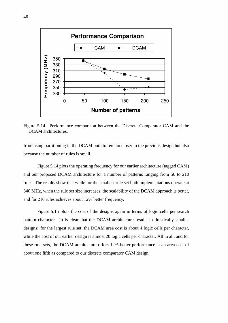
46
Performance Comparison
230
250
270
290
310
330
350
0 50 100 150 200 250
Number of patterns
F r e
q u
e n
c y
( M
H z
) CAM DCAM
Figure 5.14. Performance comparison between the Discrete Comparator CAM and theDCAM architectures.
from using partitioning in the DCAM both to remain closer to the previous design but also
because the number of rules is small.
Figure 5.14 plots the operating frequency for our earlier architecture (tagged CAM)
and our proposed DCAM architecture for a number of patterns ranging from 50 to 210
rules. The results show that while for the smallest rule set both implementations operate at
340 MHz, when the rule set size increases, the scalability of the DCAM approach is better,
and for 210 rules achieves about 12% better frequency.
Figure 5.15 plots the cost of the designs again in terms of logic cells per search
pattern character. In is clear that the DCAM architecture results in drastically smaller
designs: for the largest rule set, the DCAM area cost is about 4 logic cells per character,
while the cost of our earlier design is almost 20 logic cells per character. All in all, and for
these rule sets, the DCAM architecture offers 12% better performance at an area cost of
about one fifth as compared to our discrete comparator CAM design.
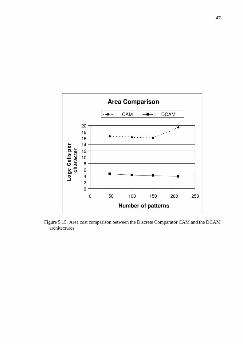
47
Area Comparison
0
2
4
6
8
10
12
14
16
18
20
0 50 100 150 200 250
Number of patterns
L o
g c
C e
l l s
p e
r
c h
a r a
c t e
r
CAM DCAM
Figure 5.15. Area cost comparison between the Discrete Comparator CAM and the DCAMarchitectures.

48
CHAPTER 6
COMPARISON
In this chapter we attempt a fair comparison with previously reported research.
While we have done our best to report these results with the most objective way, we cau-
tion the reader that this task is difficult since each system has its own assumptions and
parameters, occasionally in ways that are hard to quantify. In sections§4.2 and§5.2, we
presented performance and area cost results, to evaluate the efficiency of the proposed
architectures. We measure performance in terms of operating frequency, and throughput
(throughput = frequency × input bits). The cost is measured in terms of logic cells
needed to match a single character. Logic cells are the fundamental element of both Al-
tera’s and Xilinx’s devices3, and therefore, it is the most proper measure for evaluating the
area cost of a design. Additionally, it is important to find a metric, which combines both
performance (throughput) and area cost (logic Cells per character), in order to rank designs
taking into account both performance and cost. In the following section, we describe a per-
formance efficiency metric (PEM), similar to other researchers [7, 6, 15], which is used to
evaluate designs efficiency. After introducing PEM, a comparison between our approaches
and related work is presented. During the comparison, we use PEM, performance, and cost
results, and also analyze the characteristics of each approach. Until 2003, all research in
this area was on systems that had either high performance but were costly or systems that
had very low cost at the expense of low performance. Since then, researchers started paying
attention to the system level efficiency. Techniques such as pre-decoding, partitioning, and
character or substring sharing to minimize area cost, and fine-grain pipeline, parallelism,
and efficient data distribution network are used to improve system efficiency. According
to this research timeline, we compare first the discrete comparator architecture with older
related work (published until 2003), and then show comparison charts and present a more
detailed comparison between DCAM and recent related work.
3A logic cell consists of a 4-input LUT and a flip-flop (plus carry chain logic etc.)
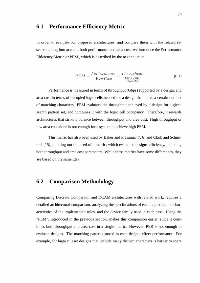
49
6.1 Performance Efficiency Metric
In order to evaluate our proposed architectures, and compare them with the related re-
search taking into account both performance and area cost, we introduce the Performance
Efficiency Metric or PEM , which is described by the next equation:
PEM =Performance
Area Cost=
ThroughputLogic CellsCharacter
(6.1)
Performance is measured in terms of throughput (Gbps) supported by a design, and
area cost in terms of occupied logic cells needed for a design that stores a certain number
of matching characters. PEM evaluates the throughput achieved by a design for a given
search pattern set, and combines it with the logic cell occupancy. Therefore, it rewards
architectures that strike a balance between throughput and area cost. High throughput or
low area cost alone is not enough for a system to achieve high PEM.
This metric has also been used by Baker and Prasanna [7, 6] and Clark and Schim-
mel [15], pointing out the need of a metric, which evaluated designs efficiency, including
both throughput and area cost parameters. While these metrics have some differences, they
are based on the same idea.
6.2 Comparison Methodology
Comparing Discrete Comparator and DCAM architectures with related work, requires a
detailed architectural comparison, analyzing the specifications of each approach, the char-
acteristics of the implemented rules, and the device family used in each case. Using the
”PEM”, introduced in the previous section, makes this comparison easier, since it com-
bines both throughput and area cost in a single metric. However, PER is not enough to
evaluate designs. The matching patterns stored in each design, effect performance. For
example, for large ruleset designs that include many distinct characters is harder to share
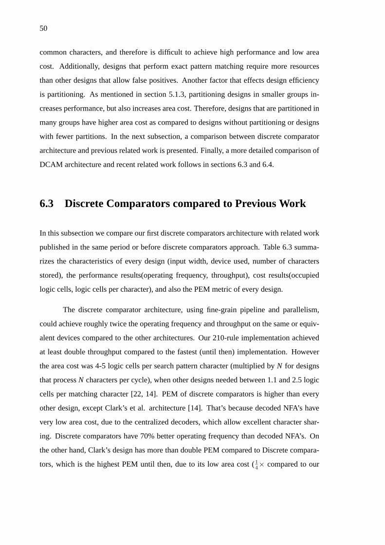
50
common characters, and therefore is difficult to achieve high performance and low area
cost. Additionally, designs that perform exact pattern matching require more resources
than other designs that allow false positives. Another factor that effects design efficiency
is partitioning. As mentioned in section 5.1.3, partitioning designs in smaller groups in-
creases performance, but also increases area cost. Therefore, designs that are partitioned in
many groups have higher area cost as compared to designs without partitioning or designs
with fewer partitions. In the next subsection, a comparison between discrete comparator
architecture and previous related work is presented. Finally, a more detailed comparison of
DCAM architecture and recent related work follows in sections 6.3 and 6.4.
6.3 Discrete Comparators compared to Previous Work
In this subsection we compare our first discrete comparators architecture with related work
published in the same period or before discrete comparators approach. Table 6.3 summa-
rizes the characteristics of every design (input width, device used, number of characters
stored), the performance results(operating frequency, throughput), cost results(occupied
logic cells, logic cells per character), and also the PEM metric of every design.
The discrete comparator architecture, using fine-grain pipeline and parallelism,
could achieve roughly twice the operating frequency and throughput on the same or equiv-
alent devices compared to the other architectures. Our 210-rule implementation achieved
at least double throughput compared to the fastest (until then) implementation. However
the area cost was 4-5 logic cells per search pattern character (multiplied byN for designs
that processN characters per cycle), when other designs needed between 1.1 and 2.5 logic
cells per matching character [22, 14]. PEM of discrete comparators is higher than every
other design, except Clark’s et al. architecture [14]. That’s because decoded NFA’s have
very low area cost, due to the centralized decoders, which allow excellent character shar-
ing. Discrete comparators have 70% better operating frequency than decoded NFA’s. On
the other hand, Clark’s design has more than double PEM compared to Discrete compara-
tors, which is the highest PEM until then, due to its low area cost (14× compared to our
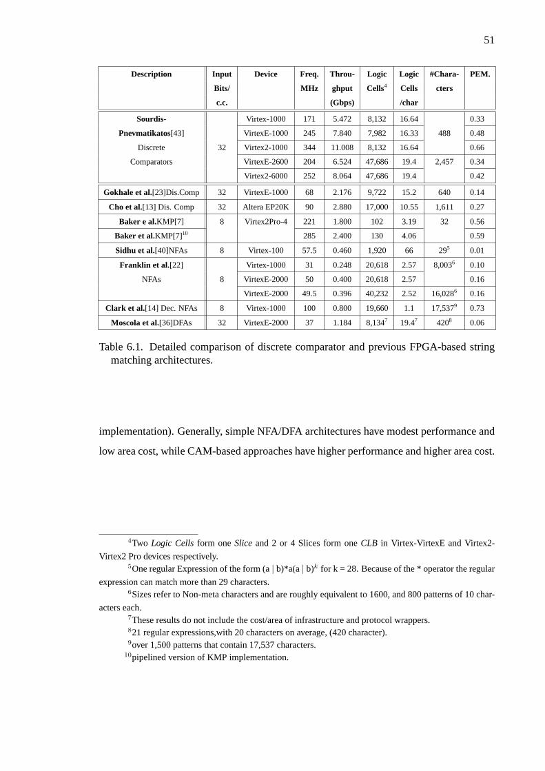
51
Description Input Device Freq. Throu- Logic Logic #Chara- PEM.
Bits/ MHz ghput Cells4 Cells cters
c.c. (Gbps) /char
Sourdis- Virtex-1000 171 5.472 8,132 16.64 0.33
Pnevmatikatos[43] VirtexE-1000 245 7.840 7,982 16.33 488 0.48
Discrete 32 Virtex2-1000 344 11.008 8,132 16.64 0.66
Comparators VirtexE-2600 204 6.524 47,686 19.4 2,457 0.34
Virtex2-6000 252 8.064 47,686 19.4 0.42
Gokhale et al.[23]Dis.Comp 32 VirtexE-1000 68 2.176 9,722 15.2 640 0.14
Cho et al.[13] Dis. Comp 32 Altera EP20K 90 2.880 17,000 10.55 1,611 0.27
Baker e al.KMP[7] 8 Virtex2Pro-4 221 1.800 102 3.19 32 0.56
Baker et al.KMP[7]10 285 2.400 130 4.06 0.59
Sidhu et al.[40]NFAs 8 Virtex-100 57.5 0.460 1,920 66 295 0.01
Franklin et al. [22] Virtex-1000 31 0.248 20,618 2.57 8,0036 0.10
NFAs 8 VirtexE-2000 50 0.400 20,618 2.57 0.16
VirtexE-2000 49.5 0.396 40,232 2.52 16,0286 0.16
Clark et al.[14] Dec. NFAs 8 Virtex-1000 100 0.800 19,660 1.1 17,5379 0.73
Moscola et al.[36]DFAs 32 VirtexE-2000 37 1.184 8,1347 19.47 4208 0.06
Table 6.1. Detailed comparison of discrete comparator and previous FPGA-based stringmatching architectures.
implementation). Generally, simple NFA/DFA architectures have modest performance and
low area cost, while CAM-based approaches have higher performance and higher area cost.
4Two Logic Cellsform oneSliceand 2 or 4 Slices form oneCLB in Virtex-VirtexE and Virtex2-
Virtex2 Pro devices respectively.5One regular Expression of the form (a| b)*a(a| b)k for k = 28. Because of the * operator the regular
expression can match more than 29 characters.6Sizes refer to Non-meta characters and are roughly equivalent to 1600, and 800 patterns of 10 char-
acters each.7These results do not include the cost/area of infrastructure and protocol wrappers.821 regular expressions,with 20 characters on average, (420 character).9over 1,500 patterns that contain 17,537 characters.
10pipelined version of KMP implementation.
52
6.4 DCAM Compared to Recent Related work
DCAM architecture, using fine-grain pipelining and parallelism, just like our first approach,
and also partitioning and centralized decoders, achieves to maintain high-speed and signif-
icantly reduces area cost (see section 5.3). In this section we compare DCAM with recent
related work. We evaluate and compare DCAM with two kinds of architecture, the first one
performs exact matching [6, 5, 12, 15] and the second one allows false positives and hence
has lower area cost [6, 18]. All researchers that designed architectures for exact matching,
followed a common solution in order to increase character sharing and reduce cost, the
use of centralized character decoders or ”pre-decoding”. On the other hand, designers that
their architectures do not output only true positives, chose to use approximate filtering or
pre-filtering or exclusion-based string matching. Practically, this means that small high-
speed modules are used to provide quick negatives when the search pattern does not exist
in the incoming data. Incoming packets that are not excluded, may indeed match NIDS
rules or may constitute false positive. We will first provide a detailed comparison with ex-
act matching architectures explaining any architectural and performance differences. After
that, we offer a comparison between DCAM and approximate filtering architectures. We
should take into account, though, that architectures , which allow false positives, require
lower area cost.
A very similar architecture compared to DCAM was presented by Baker and Prasanna.
The most important difference of their ”Unary” approach is that they chose to give more
effort in pre-processing patterns before implementation, in order to group together patterns
with similarities. Another difference is that they did not use SRL16 shift registers to delay
the decoded data, and preferred to use regular registers instead. This decision has higher
area cost, since, in general, more registers than SRL16 are needed to shift the decoded data
(Figure 6.1). They implemented about the same number of characters in a single device
(about 19,000 characters), but they report that their set of patterns has about 100 distinct
characters, which is reduced to 75 distinct characters, because they perform case insen-
sitive matching. On the other hand, our designs store about 1,500 patterns (over 18,000

53
Decoded
“a” SR2 SR4 SR16
DCAM uses shift registers (SLR16 xilinx cells)
Decoded
“a”
FF
2
to AND-trees
Baker uses registers
FF
1
FF
3
FF
4
FF
15
FF
16
to AND-trees
Figure 6.1. Baker and DCAM approaches for shifting decoded data. Baker uses 1-bitregisters to shift decoded data, while DCAM uses SRL16 shift registers. Each SLR16Xilinx cell fits in a single logic cell, and has programmable width up to 16. In this case,baker’s approach needs 16 logic cells, while DCAM needs only 3 logic cells. Generally,decoded data do not need to be shifted in every offset. So, in average case DCAMrequires fewer resources for shifting.
characters), having more than 200 distinct characters, and we distinguish characters of dif-
ferent case (upper/lower case). Therefore, it is clear that sharing characters is harder for
the set of patterns we used. In addition, Baker and Prasanna use partitioning, much like we
use in DCAM arhitecture. However, Unary architecture has smaller area overhead for data
distribution. DCAM approach uses slow wide buses do distribute incoming data, which
are converted to narrow and high speed busses to match the processing speed. This de-
cision allows our system to operate in higher operating frequency, but increases its area
cost. These differences justify why DCAM designs support higher throughput, and have
(equally) higher area cost. A more detailed comparison follows in the next paragraphs,
trying to compare designs with similar characteristics i.e. datapath width, partition size,
and total number of matching characters. Figure 6.2 shows the throughput, area cost and
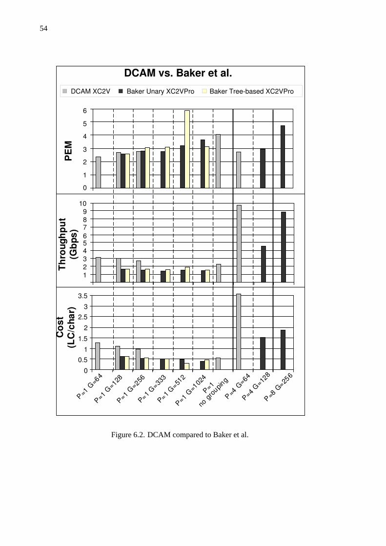
54
T h
r o u
g h
p u
t
( G b
p s )
P = 1 G
= 6 4
P = 1 G
= 1 2 8
P = 1 G
= 2 5 6
P = 1 G
= 3 3
3
P = 1 G
= 5 1
2
P = 1 G
= 1 0 2
4
P = 4 G
= 6 4
P = 4 G
= 1 2 8
P = 8 G
= 2 5 6
C o
s t
( L C
/ c h
a r )
DCAM vs. Baker et al.
0
1
2
3
4
5
6
P E
M
DCAM XC2V Baker Unary XC2VPro Baker Tree-based XC2VPro
1
2
3
4 5 6
7 8
9
10
0
0.5
1
1.5
2
2.5
3
3.5
P = 1
n o g
r o u p
i n g
Figure 6.2. DCAM compared to Baker et al.

55
PEM comparison between DCAM and Baker approaches.
We first compare DCAM with Baker’s ”Unary” designs that process one incoming
byte every cycle, store about the same number of characters (18k-19k), and have similar
partition size (128 and 256 patterns per partition). In these designs DCAMs have about 2
times higher area cost. That’s in part because Baker et al. implemented case insensitive pat-
terns, have fewer distinct characters with the same number of patterns, and hence have bet-
ter character sharing; also they avoid a significant area overhead by using a more efficient
partitioning algorithm (mincut), and not implementing an incoming data distribution net-
work.However, DCAM’s throughput is 2 times higher, regardless of the slower device fam-
ily we use (DCAM is implemented in Virtex2, while Baker et al. used Virtex2Pro). That’s
because, in order to maintain performance, during DCAM implementation, we decided to
replicate SRL16 cells, so that the fan-out does not exceed 16. Additionally, DCAM’s data
distribution network does not limit performance. For these cases, both DCAM’s and Unary
designs have about equal performance efficiency metric. Baker et al. also implemented
designs with larger partitions (333, 512 and 1024 patterns per partition), while we imple-
mented a DCAM design that is not partitioned. These designs achieve similar efficiency,
performance, and area cost. For designs with 4 bytes datapath, DCAM supports more than
twice throughput, while has more than twice the area cost, having again similar efficiency.
Baker’s 8-byte datapath design stores about 400 patterns (less than 30% of DCAM ruleset),
and has only 4 partitions. The efficiency of this design is higher than DCAM’s, however
the supported throughput still falls short.
Baker’s tree-based approach [5], supports similar throughput, and slightly better
area cost, compared to their earlier Unary architecture. Tree-based implementations have
slightly lower area cost compared to DCAM because they allow substring sharing, while
DCAM can share only character comparators. DCAM achieves higher throughput, and has
better or similar PEM (except one tree-based implementation) vs. tree-based architecture.
Figure 6.3 summarizes the PEM, throughput and cost comparison between DCAM
and decoded NFAs [15]. DCAM achieves about 15%-50% better throughput as compared
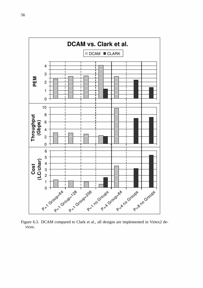
56
DCAM vs. Clark et al.
P = 1 G
r o u p
= 6 4
P = 1 G
r o u p
= 1 2 8
P = 1 G
r o u p
= 2 5 6
P = 1 n o
G r o
u p s
P = 4 G
r o u p
= 6 4
P = 4 n o
G r o
u p s
P = 8 n o
G r o
u p s
C o
s t
( L C
/ c h
a r )
T h
r o u
g h
p u
t
( G b
p s )
P E
M
DCAM CLARK
0
1
2
3
4
0
2
4
6
8
10
0
1
2
3
4
5
6
Figure 6.3. DCAM compared to Clark et al., all designs are implemented in Virtex2 de-vices.
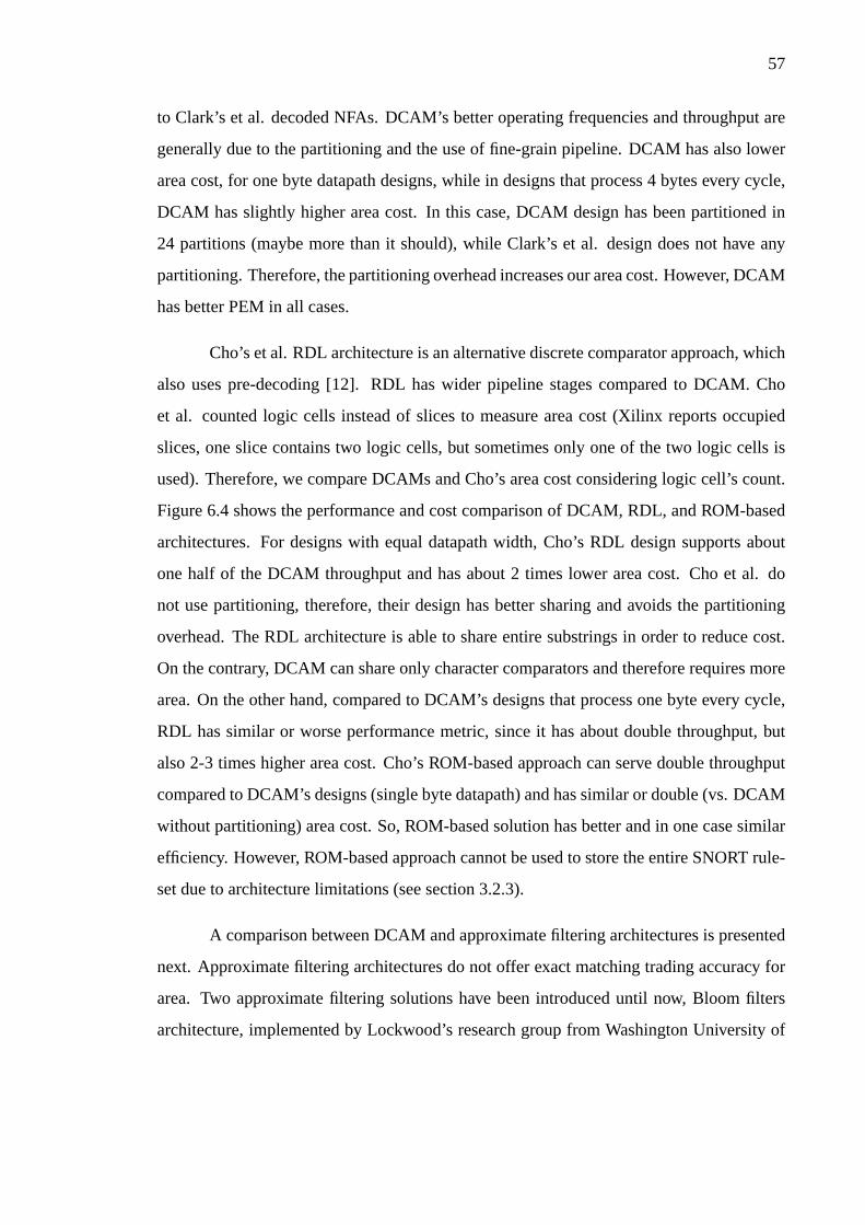
57
to Clark’s et al. decoded NFAs. DCAM’s better operating frequencies and throughput are
generally due to the partitioning and the use of fine-grain pipeline. DCAM has also lower
area cost, for one byte datapath designs, while in designs that process 4 bytes every cycle,
DCAM has slightly higher area cost. In this case, DCAM design has been partitioned in
24 partitions (maybe more than it should), while Clark’s et al. design does not have any
partitioning. Therefore, the partitioning overhead increases our area cost. However, DCAM
has better PEM in all cases.
Cho’s et al. RDL architecture is an alternative discrete comparator approach, which
also uses pre-decoding [12]. RDL has wider pipeline stages compared to DCAM. Cho
et al. counted logic cells instead of slices to measure area cost (Xilinx reports occupied
slices, one slice contains two logic cells, but sometimes only one of the two logic cells is
used). Therefore, we compare DCAMs and Cho’s area cost considering logic cell’s count.
Figure 6.4 shows the performance and cost comparison of DCAM, RDL, and ROM-based
architectures. For designs with equal datapath width, Cho’s RDL design supports about
one half of the DCAM throughput and has about 2 times lower area cost. Cho et al. do
not use partitioning, therefore, their design has better sharing and avoids the partitioning
overhead. The RDL architecture is able to share entire substrings in order to reduce cost.
On the contrary, DCAM can share only character comparators and therefore requires more
area. On the other hand, compared to DCAM’s designs that process one byte every cycle,
RDL has similar or worse performance metric, since it has about double throughput, but
also 2-3 times higher area cost. Cho’s ROM-based approach can serve double throughput
compared to DCAM’s designs (single byte datapath) and has similar or double (vs. DCAM
without partitioning) area cost. So, ROM-based solution has better and in one case similar
efficiency. However, ROM-based approach cannot be used to store the entire SNORT rule-
set due to architecture limitations (see section 3.2.3).
A comparison between DCAM and approximate filtering architectures is presented
next. Approximate filtering architectures do not offer exact matching trading accuracy for
area. Two approximate filtering solutions have been introduced until now, Bloom filters
architecture, implemented by Lockwood’s research group from Washington University of
58
P = 4 G
= 6 4
1 5 k
c h a r
P = 4
R O
M - b
a s e d
DCAM vs. Cho et al. P
E M
DCAM CHO
T h
r o u
g h p
u t
( G b
p s )
P = 1
G = 6 4
P = 1
G = 1 2
8 P = 1
G = 2 5
6 P = 4
G = 6 4
P = 4
R D L
C o
s t
( L C
/ c h
a r )
0
0.5
1
1.5
2
2.5
3
3.5
4
0.0
1.0
2.0
3.0
4.0
5.0
6.0
0
0.5
1
1.5
2
2.5
3
3.5
P = 1
n o g
r o u p
s
Figure 6.4. DCAM compared to Cho et al., all designs are implemented in Spartan3 de-vices. The DCAM area results are Flip-Flop count andnot Slice-count (see section5.2.2), since Cho et al. counts logic cells and not Slices.
59
St. Louis [18, 4], and Baker’s ”Pre-filtering” architecture [6].
DCAM, compared to Baker’s ”Pre-filtering” architecture, has again about 50% bet-
ter throughput (using slower device), however, its area cost is about 6 times higher. In
this case Baker’s design stores only 200 patterns, while DCAMs store almost 1,500 (24
partitions). Therefore, the partitioning overhead increases DCAM’s area cost dramatically.
Since it is not guaranteed that the start of the matched string will be word-aligned, we repli-
cated matching logicP times (P = degree of parallelism). However, Baker et al. replicate
only the decoder logic and just OR the decoded characters. Hence, the rest of their datapath
is exactly the same as in their one-byte Unary implementation. This means that the only
overhead in Baker’s 4-byte ”pre-filtering” architecture is the replication of decoder -which
is relatively negligible. The probability of positive match for ”pre-filtering” approach is
very small (considering that the incoming bytes are completely random), however, com-
pared to the probability of a true positive, the probability of false positives is significant.
Therefore, it’s expectable for DCAM designs to have at least 4 times higher area cost com-
pared to Baker’s designs that process 4-bytes every cycle.
String matching using Bloom Filters [9] (BFs) is another approximate filtering ap-
proach introduced by Lockwood et al. [18]. Bloom filters can store a very large number
of patterns (a single BF can store over 1400 patterns), however each BF can match only
patterns of the same length, and indicates that some pattern has matched without specifying
which one. Therefore, the use of Bloom filters is a very interesting approach, but there are
significant drawbacks to face. Lockwood’s et al. implementation can store over 35,000
patterns, and supports 0.5 Gbps throughout. On the other hand, due to device limitations it
is difficult, if not impossible to store patterns of every length in a single device. Compared
to DCAM, Bloom filters can store about twenty times more characters, with about 7-10
times less are cost without taking into account the internal block RAMs, however DCAM
achieves about 3-4 times better throughput (consideringthe device families used- Virtex2
is about 50% better compared to VirtexE).
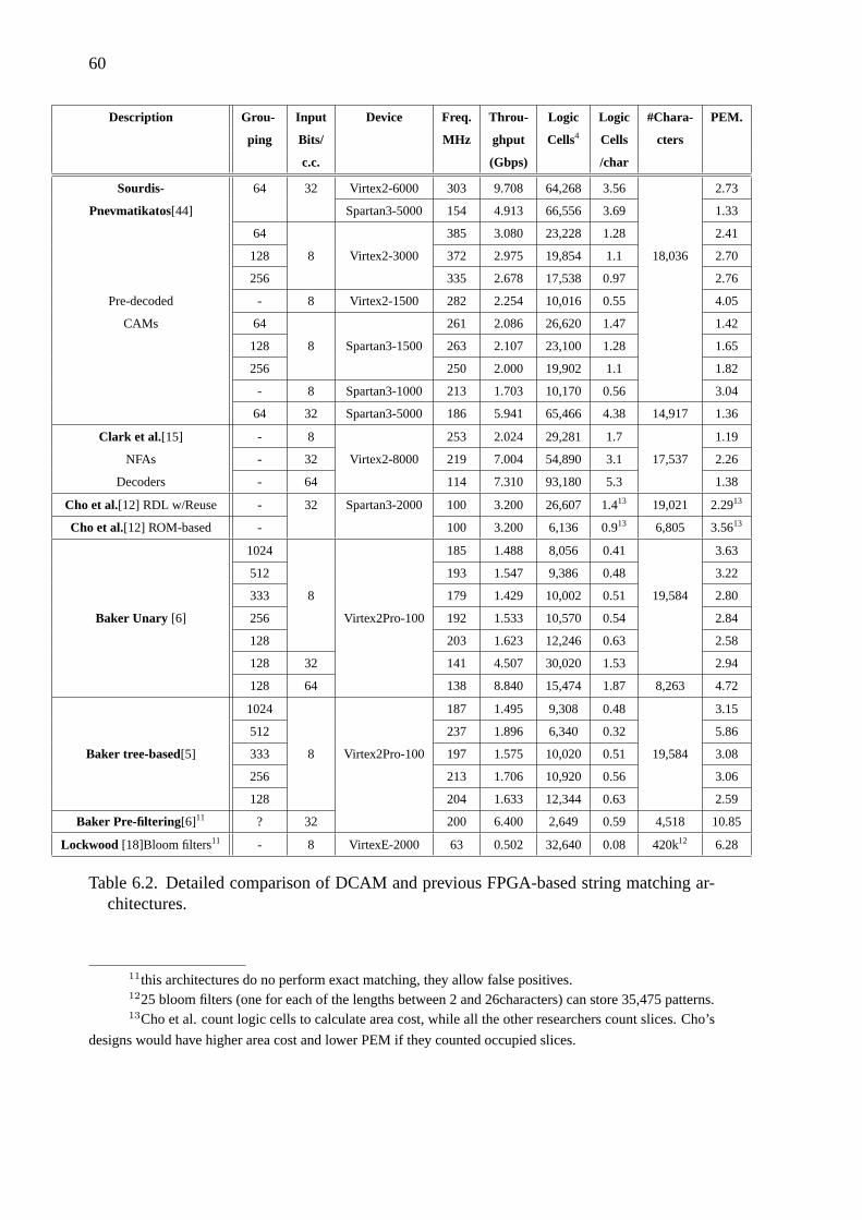
60
Description Grou- Input Device Freq. Throu- Logic Logic #Chara- PEM.
ping Bits/ MHz ghput Cells4 Cells cters
c.c. (Gbps) /char
Sourdis- 64 32 Virtex2-6000 303 9.708 64,268 3.56 2.73
Pnevmatikatos[44] Spartan3-5000 154 4.913 66,556 3.69 1.33
64 385 3.080 23,228 1.28 2.41
128 8 Virtex2-3000 372 2.975 19,854 1.1 18,036 2.70
256 335 2.678 17,538 0.97 2.76
Pre-decoded - 8 Virtex2-1500 282 2.254 10,016 0.55 4.05
CAMs 64 261 2.086 26,620 1.47 1.42
128 8 Spartan3-1500 263 2.107 23,100 1.28 1.65
256 250 2.000 19,902 1.1 1.82
- 8 Spartan3-1000 213 1.703 10,170 0.56 3.04
64 32 Spartan3-5000 186 5.941 65,466 4.38 14,917 1.36
Clark et al. [15] - 8 253 2.024 29,281 1.7 1.19
NFAs - 32 Virtex2-8000 219 7.004 54,890 3.1 17,537 2.26
Decoders - 64 114 7.310 93,180 5.3 1.38
Cho et al.[12] RDL w/Reuse - 32 Spartan3-2000 100 3.200 26,607 1.413 19,021 2.2913
Cho et al.[12] ROM-based - 100 3.200 6,136 0.913 6,805 3.5613
1024 185 1.488 8,056 0.41 3.63
512 193 1.547 9,386 0.48 3.22
333 8 179 1.429 10,002 0.51 19,584 2.80
Baker Unary [6] 256 Virtex2Pro-100 192 1.533 10,570 0.54 2.84
128 203 1.623 12,246 0.63 2.58
128 32 141 4.507 30,020 1.53 2.94
128 64 138 8.840 15,474 1.87 8,263 4.72
1024 187 1.495 9,308 0.48 3.15
512 237 1.896 6,340 0.32 5.86
Baker tree-based[5] 333 8 Virtex2Pro-100 197 1.575 10,020 0.51 19,584 3.08
256 213 1.706 10,920 0.56 3.06
128 204 1.633 12,344 0.63 2.59
Baker Pre-filtering [6]11 ? 32 200 6.400 2,649 0.59 4,518 10.85
Lockwood [18]Bloom filters11 - 8 VirtexE-2000 63 0.502 32,640 0.08 420k12 6.28
Table 6.2. Detailed comparison of DCAM and previous FPGA-based string matching ar-chitectures.
11this architectures do no perform exact matching, they allow false positives.1225 bloom filters (one for each of the lengths between 2 and 26characters) can store 35,475 patterns.13Cho et al. count logic cells to calculate area cost, while all the other researchers count slices. Cho’s
designs would have higher area cost and lower PEM if they counted occupied slices.
61
Table 6.4 summarizes performance, cost and PEM results of DCAM and all the
above FPGA-based string matching architectures. In all cases, DCAM achieves better
throughput for designs that store the entire SNORT rule-set in a single device, and have
equal datapath width. DCAM’s area cost is in some cases two to three times higher than
others. However, the differences between implemented rule-set, and different partitioning
strategies should be considered. Based on performance efficiency metric, DCAM has worse
(about23) or similar efficiency compared ROM-based approach, similar PEM compared to
Unary, tree-based, and RDL designs (comparing Unary and tree-based designs with similar
partition size), and better compared to decoded NFAs. Finally, compared to approximate
filtering approaches, DCAM has 1.5 to 3 times lower efficiency, since it requires higher
area cost, but supports higher throughput.
6.5 Summary
In this chapter we tried to analyze different string matching approaches, and compare them
with discrete comparator and DCAM architectures, presented in this thesis. It is clear that
each approach has often different specifications, i.e. accuracy, ruleset (case (in)sensitive,
size), device family etc. Each approach is compared in terms of operating frequency,
throughput, and area cost. Additionally, a performance efficiency metric was introduced
to evaluate designs.
Considering PEM, our discrete comparator’s approach (chapter 4), presented in
2003[43], was better compared to all previous approaches (Sidhu et al.[40], Franklin et
al. [22], Moscola et al. [36], Lockwood [34], Gokhale et al. [23]) and slightly better
compared to Baker’s KMP approach [7] (regardless of the slower devices used). DCAM
solution (chapter 5)is about 5 times better to our earlier architecture as mentioned in sec-
tion 5.3. The performance metrics of our DCAM designs are comparable or better than
other recent researchers’ results. In some cases, DCAM’s area cost is higher than other
architectures, however, its supported throughput is the best published until now. Compared
to architectures that perform exact match (Cho et al., Baker et al. 1 -byte architecture,
62
Clark et al.), DCAM has better throughput and similar or slightly worse area cost. Com-
pared to designs that allow false positives (Lockwood bloom filters, Baker et al. 4-byte
architecture), DCAM still supports better throughput (32× Baker et al.,4× Lockwood et
al.), and has about 5 times higher area cost. Summarizing, fine-grain pipelining, paral-
lelism and partitioning, make DCAM designs to achieve the best published throughput.
DCAM uses pre-decoding to increase character sharing, however this architecture does not
allow substring sharing, and hence has in some cases higher area cost. On the other hand,
decoded-CAM is a flexible architecture, which can easily be improved. The DCAM design
that is not partitioned has better efficiency as compared to DCAM designs with partition-
ing. That’s because its area cost is halved and its performance is about 20-25% worse. The
next chapter proposes some improvements for DCAM, that would reduce even more cost,
and increase its efficiency.
63
CHAPTER 7
CONCLUSIONS & FUTURE WORK
7.1 Conclusions
Throughout this work we discussed string matching as the major performance bottleneck
in intrusion detection systems. We proposed new string matching micro-architectures and
investigated the efficiency of FPGA-based solutions. We first accented the role of string
matching in intrusion detection systems. String matching is the most computational in-
tensive part of such systems and limits their performance. Further, we analyzed the set
of NIDS patterns, grouping them by length, and also summarizing characters occurrence.
Additionally, in this thesis we discussed briefly software-based solutions, ASIC and FPGA-
based NIDS architectures. Intrusion detection systems running on general purpose proces-
sors have limited performance, while on the contrary, ASIC and FPGA-based systems can
achieve better performance. In particular, FPGAs offer the flexibility needed in such sys-
tems for fast ruleset update.
This work shows that FPGAs are well suited for implementing intrusion detection
systems, achieving high speed processing in reasonable cost. Our results offer a distinct
step forward compared to previously published research. DCAM designs support up to
OC192 processing bandwidth (10 Gbps), storing the entire set of NIDS patterns in a sin-
gle, large FPGA14(4-byte datapath), and about 3 Gbps throughput requiring medium size
devices15(for 1-byte datapath). FPGAs offer the ability of fast reconfiguration, this FPGA
characteristic combined with fast VHDL code generation are important to NIDS systems
that have to be often updated. In this thesis we developed a C program for automatic
VHDL generation. The entire implementation flow (pattern extraction, pre-processing,
14In a single 33,000-slices device (about 66,000 logic cells), while the largest existing Xilinx device
contains about 55,000 slices (110,000 logic cells).15In a single 10,000-slices device (about 20,000 logic cells).
64
VHDL generation, synthesis, Place & Route), described in appendix A.1, offers fast imple-
mentation of large designs.
In order to achieve high performance, we were the first who used the following
techniques in this particular field:
• Fine-grain pipeline
• Partitioning
• efficient data distribution network
• fan-out control
Further, just like other researchers, in order to increase processing bandwidth, DCAM ex-
ploits parallelism. Parallelism offers the ability to trade area for throughput, and choose the
proper configuration for a specific system. Centralized character comparators (decoders)
are used to share matching logic, and reduce DCAM area cost. All the above, adapted in
FPGA structure, lead to efficient string matching modules, that can be fast implemented
and easily reconfigured.
Decoded CAMs operate at high frequency and require a modest area cost for their
implementation. Compared to other research that perform exact match, DCAMs have at
least comparable efficiency, can support better throughput than any other architecture and
have about 2 times higher area cost as compared to the best published designs with simi-
lar characteristics. Finally, our proposed architecture offers simplicity and regularity, and
hence it is straightforward to integrate DCAM sub-modules in a more complete and sophis-
ticated intrusion detection system.
7.2 Future Work
Despite the significant body of research in this area, there are still improvements that we can
use to seek better solutions. Our proposed architecture achieves high-speed and low cost

65
FPGA-based string matching for Intrusion Detection Systems. However, there are several
problems to deal with, and a few improvements that can be done in order to reduce the
area cost of the system, and make our system more compete. Additionally, using DCAM
architecture as part of a more sophisticated architecture would probably lead to a better
solution with much lower area cost.
DCAM architecture has many parameters that effect systems performance and cost
(i.e. the group size, level of parallelism etc.). Therefore, generating different designs by
changing these parameters would indicate which group size leads to the best designs and
would also analyze a cost/performance tradeoff for different level of parallelism. Another
parameter we have not explored in detail is the width of pre-decoded incoming data. In
this work we used 8 bits. However, we could consider different widths such as 4 bits (a
single nibble fitting in a LUT), or 12 bits, etc. Narrower decoders may prove beneficial
since they may increase the degree of sharing of decoder terms even further but require
wider AND gates to determine the pattern match. A comparison of the effect of these
parameters on the performance and cost of DCAMs would be very interesting. DCAM can
share common characters, however this architecture is not able to share entire substrings.
Implementation results of other architectures showed that sharing entire substring can save
significant amount of area [5].
An evaluation of the partitioning alternatives would also be very interesting. Our
partitioning algorithm is greedy, and hence may leave room for further improvements. A
more sophisticated algorithm could take into account the exact location of the similarities
between search patterns (in order to increase the degree of shift register sharing), and would
use a global instead of local approach to cost minimization.
Just like other architectures, DCAM must handle the problem of multiple matches
in the same cycle. Since more than one patterns may match in one clock cycle, there must
be a mechanism that reports all of them or an encoder that gives priority to the most sig-
nificant one. A software that detects which patterns may possibly match at the same time,
would be very useful, and joined with a sophisticated priority encoder would hopefully
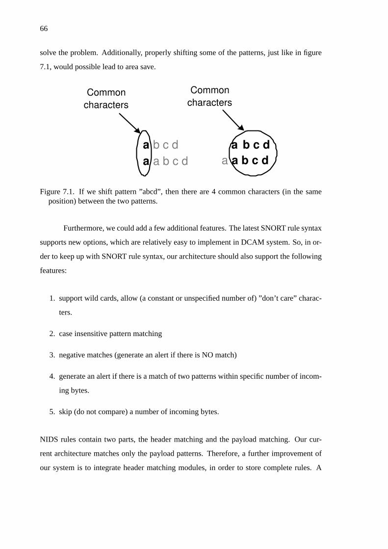
66
solve the problem. Additionally, properly shifting some of the patterns, just like in figure
7.1, would possible lead to area save.
a b c d
a a b c d
Common
characters
a b c d
a a b c d
Common
characters
Figure 7.1. If we shift pattern ”abcd”, then there are 4 common characters (in the sameposition) between the two patterns.
Furthermore, we could add a few additional features. The latest SNORT rule syntax
supports new options, which are relatively easy to implement in DCAM system. So, in or-
der to keep up with SNORT rule syntax, our architecture should also support the following
features:
1. support wild cards, allow (a constant or unspecified number of) ”don’t care” charac-
ters.
2. case insensitive pattern matching
3. negative matches (generate an alert if there is NO match)
4. generate an alert if there is a match of two patterns within specific number of incom-
ing bytes.
5. skip (do not compare) a number of incoming bytes.
NIDS rules contain two parts, the header matching and the payload matching. Our cur-
rent architecture matches only the payload patterns. Therefore, a further improvement of
our system is to integrate header matching modules, in order to store complete rules. A
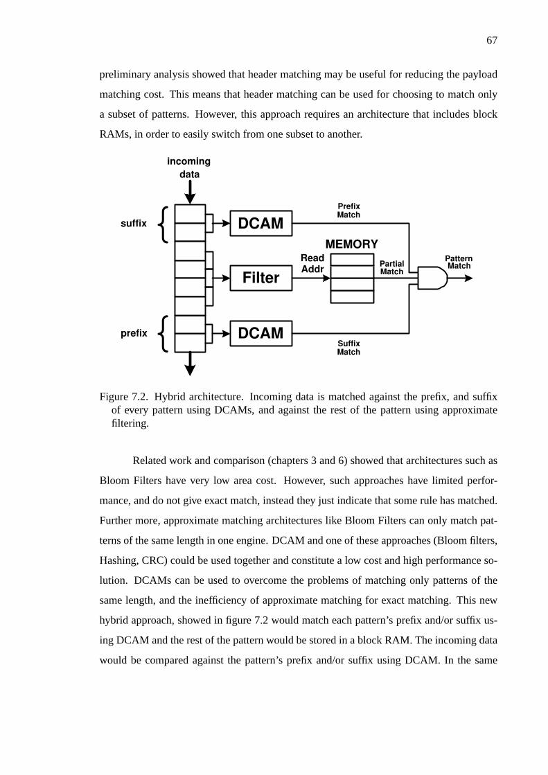
67
preliminary analysis showed that header matching may be useful for reducing the payload
matching cost. This means that header matching can be used for choosing to match only
a subset of patterns. However, this approach requires an architecture that includes block
RAMs, in order to easily switch from one subset to another.
incoming
data
{ DCAM
DCAM
Filter
{
suffix
prefix
Read Addr
MEMORY
Partial Match
Prefix Match
Suffix Match
Pattern Match
Figure 7.2. Hybrid architecture. Incoming data is matched against the prefix, and suffixof every pattern using DCAMs, and against the rest of the pattern using approximatefiltering.
Related work and comparison (chapters 3 and 6) showed that architectures such as
Bloom Filters have very low area cost. However, such approaches have limited perfor-
mance, and do not give exact match, instead they just indicate that some rule has matched.
Further more, approximate matching architectures like Bloom Filters can only match pat-
terns of the same length in one engine. DCAM and one of these approaches (Bloom filters,
Hashing, CRC) could be used together and constitute a low cost and high performance so-
lution. DCAMs can be used to overcome the problems of matching only patterns of the
same length, and the inefficiency of approximate matching for exact matching. This new
hybrid approach, showed in figure 7.2 would match each pattern’s prefix and/or suffix us-
ing DCAM and the rest of the pattern would be stored in a block RAM. The incoming data
would be compared against the pattern’s prefix and/or suffix using DCAM. In the same
68
time the rest of the incoming data would be transformed into block RAMs read address us-
ing a logic function. If the element read from the memory is ”1” the substring is matched.
The partial matches (prefix, suffix, substring) are AND-ed to produce the pattern’s match.
The substring can maintain a constant length if we properly change the prefix or/and the
suffix lengths. Additionally, this architecture gives exact matches if each pattern has a
unique prefix or suffix. Since, the operating frequency of block RAMs is limited, we can
also exploit both block RAM ports in order to double their throughput and maintain high
performance. Finally, the false positive probability is reduced, since only a part of every
pattern is matched using approximate matching.
We plan to investigate this new approach and all the above issues further in or-
der to further improve our approach or possibly convert it to a hybrid, more sophisticated
architecture.

69
APPENDIX A
IMPLEMENTATION DETAILS
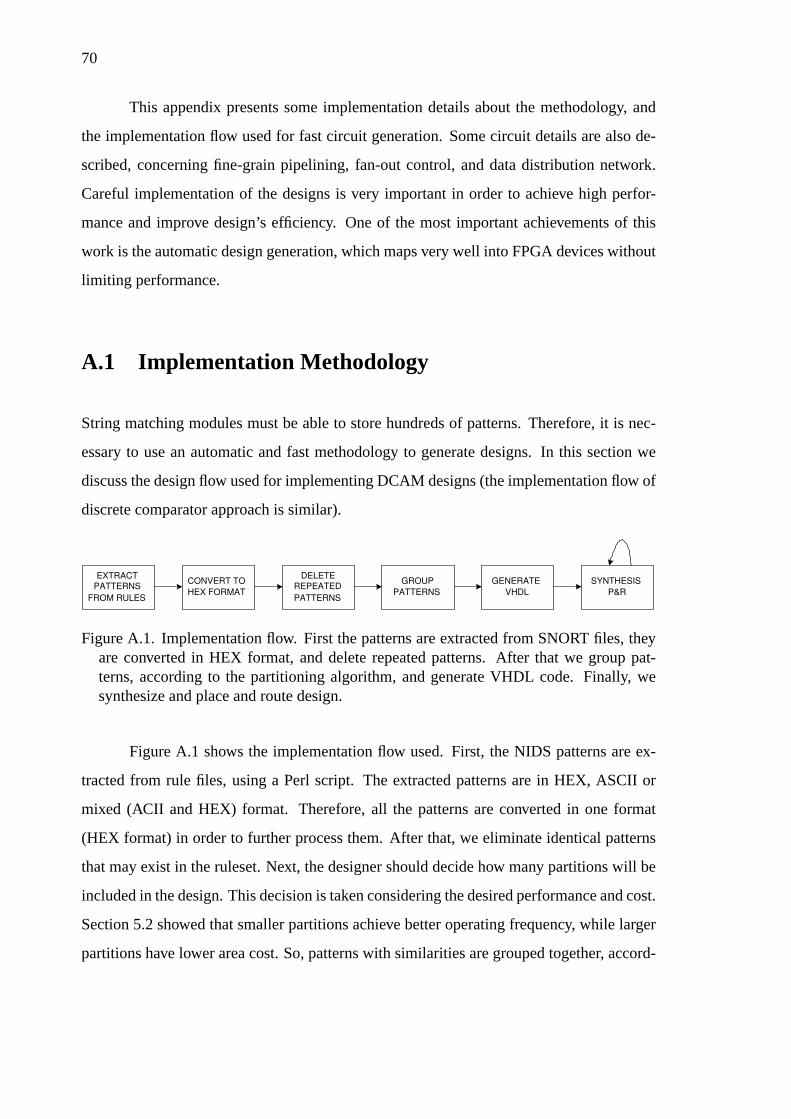
70
This appendix presents some implementation details about the methodology, and
the implementation flow used for fast circuit generation. Some circuit details are also de-
scribed, concerning fine-grain pipelining, fan-out control, and data distribution network.
Careful implementation of the designs is very important in order to achieve high perfor-
mance and improve design’s efficiency. One of the most important achievements of this
work is the automatic design generation, which maps very well into FPGA devices without
limiting performance.
A.1 Implementation Methodology
String matching modules must be able to store hundreds of patterns. Therefore, it is nec-
essary to use an automatic and fast methodology to generate designs. In this section we
discuss the design flow used for implementing DCAM designs (the implementation flow of
discrete comparator approach is similar).
EXTRACT
PATTERNS
FROM RULES
CONVERT TO
HEX FORMAT
DELETE
REPEATED
PATTERNS
GENERATE
VHDL
SYNTHESIS
P&R
GROUP
PATTERNS
Figure A.1. Implementation flow. First the patterns are extracted from SNORT files, theyare converted in HEX format, and delete repeated patterns. After that we group pat-terns, according to the partitioning algorithm, and generate VHDL code. Finally, wesynthesize and place and route design.
Figure A.1 shows the implementation flow used. First, the NIDS patterns are ex-
tracted from rule files, using a Perl script. The extracted patterns are in HEX, ASCII or
mixed (ACII and HEX) format. Therefore, all the patterns are converted in one format
(HEX format) in order to further process them. After that, we eliminate identical patterns
that may exist in the ruleset. Next, the designer should decide how many partitions will be
included in the design. This decision is taken considering the desired performance and cost.
Section 5.2 showed that smaller partitions achieve better operating frequency, while larger
partitions have lower area cost. So, patterns with similarities are grouped together, accord-

71
ing to the program described in section 5.1.4. This program also calculates the number of
distinct characters in each group, and the average number of distinct characters.
When all the groups of patterns are specified, the VHDL representation of the de-
sign can be generated. A C program that generates VHDL code has been developed . This
program has the following parameters:
• level of parallelism. Designer can decide how many incoming bytes will be processed
every clock cycle. Processing many bytes every cycle achieves better performance,
while designs that process one byte have lower area cost.
• width of data distribution busses. The width of data distribution busses is also param-
eterizable. Practically, the best choice is to implement buses that have double width
compared to the processing datapath.
After VHDL generation, we synthesize, and Place & Route design. P&R procedure
may be repeated several time using, changing the target operating frequency and sometimes
other parameters, in order to achieve the desired operating frequency. However, we can
minimize P&R time by choosing incremental flow.
A.2 Circuit Details
The method by which VHDL code of a DCAM design is generated was described in the
previous section. We will discuss here how this VHDL design representation maps in
FPGA device, and also a few more implementation details.
Both discrete comparator and DCAM architectures use fine-grain pipelining to
maintain high performance. Figure A.2 shows the way discrete comparator and DCAM
designs map into FPGA. The entire design is pipelined, based on the observation that the
minimum amount of logic in each pipeline stage can fit in a 4-input LUT and its corre-
sponding register. This decision was made based on the structure of FPGAs logic cell. In

72
LUT
Flip-Flop
Logic Cell
Flip-Flop
Logic Cell
Flip-Flop
Logic Cell
LUT
LUT
Pipeline Stage
Figure A.2. The entire design is pipelined. Every pipeline stage fits in parallel 4-inputLUTs and the corresponding registers. The registers already exist, since every logic cellhas an LUT and a register, So there is no pipeline area overhead. Hence, the operatingperiod is equal to the logic cell delay plus the wire delay (routing).
the resulting pipeline, the clock period is the sum of wire delay (routing) plus the delay of
a single logic cell (one 4-input LUT + 1 flip-flop). The area overhead cost of this pipeline
is zero since each logic cell used for combinational logic also includes a flip-flop.
In section 5.1.3 we described the use of multiple clocks, one slow to distribute
data across long distances, and a fast clock for the smaller and faster partitioned matching
function. the Figure A.3 shows the two modules that are implemented to switch from slow
to fast clock domain and reverse. The”slow to fast” module uses a multiplexer to choose
half of the incoming data to the output, its select input is connected to the slow clock, and
the input and output ports are registered. The”fast to slow” module uses a de-multiplexer
and has the opposite functionality.
We experimentally found that the optimal fan-out from a register is 16, since if fan-
out exceeds 16 then the operating frequency drops about 30%. Therefore, the program that

73
CLK/2 M
U X
N*2 N
N
N
CLK
M U
X
N*2 N
N
N
CLK CLK/2
Slow to Fast Fast to Slow
Figure A.3. ”Slow to Fast” and ”Fast to slow” modules. they use a multiplexer and de-multiplexer respectively to switch from one clock domain to another.
generates VHDL code makes sure that the fanout is equal or less than 16. When more that
16 wires have the same source (register), then the VHDL generator replicates the source
logic cell. Xilinx ISE tool can also control the fan-out, however ISE replicates only the
register and not the entire logic cell. If only the register is replicated, then the operating
frequency drops, since the LUT output must traverse out of the logic cell (Figure A.4).
The most complicated part of the VHDL generator is the implementation of shift
registers that feed the comparators AND-trees. Figure A.5 presents an abstract pseudo-code
that describes how VHDL generator implements the ”shift-register’part of the design. For
each different character there is an array that keeps the number of wires needed from each
offset (shift register) to an AND-tree. For each new shift register, the pseudo-code finds the
closest available shift register that can be used as source, if there is not, creates one. Figure
A.6 shows the implementation of the shift register circuit for the given array. For the 18th
position we need two shift registers (SR18A, andSR18B), since fan-out must be equal or
less than 16. These two shift registers cannot useSR4 as source, because SR4 already has
supplies 16 wires. So the next available shift register within the supported range (max D)
is SR2.
All the above increase DCAM’s efficiency in terms of both performance and area
utilization.

74
LUT
Flip-Flop
Logic Cell
No fan-out
control More than
16 wires
LUT
Flip-Flop
Xilinx
fan-out control
LUT
Flip-Flop
Less than
16 wires
Less than
16 wires
LUT
Flip-Flop
DCAM
fan-out control
LUT
Flip-Flop
Less than
16 wires
Less than
16 wires
Logic Cell
Logic Cell
Logic Cell
Logic Cell
Figure A.4. Fan-out control is achieved by replicating logic. However, if only the registeris replicated, then operating frequency drops, since the wire that connects the LUT withthe second register is longer than it should. In order no to add any more delay in thecritical paths, we decided to replicate the entire logic cell. This solution does not haveany area overhead, because the second logic cell used already contains an LUT.

75
for (every character ch=0;ch<256;ch++){
for (i=N;i>0;i++){
//N is the maximum pattern length (plus offset in case of parallelism)
for (j=0;j<CHAR[ch][i]%16;j++)
//CHAR array contains the number of wires needed for every character in
//every position (offset)
//16 is the maximum fan-out
if (the position "P" of first non-zero CHAR[ch][] element is closer than 16
and its value%16!=0){
//search for a source that allready exist for the shift register
use it as source for the implemented shift register;
D=calculate the distance;
}
else{
//create a source for the shift register
create another shift register in position max_D;
//used it as source for the shift register
CHAR[ch][i-max_D]++;
//max_D is the maximum distance that one shift register can cover,
//max_D<=17
D=max_D;
}
implement a shift register with distance D and source..the one found or created;
}
}
Figure A.5. This is an abstract pseudo-code that describes the shift register part of VHDLgenerator.
Decoded
“a” SR2 SR4
16 2
SR18A
16
SR18B
4
to AND-trees
Fan-out: 1 5 16 16 4
0 Array of
character “a” 20 0 0 16 0 2
Index: 1 2 3 4 16 17 18
IMPLEMENTATION
Figure A.6. This is the implementation of shift register part for the given array of character”a”. VHDL generator, creates the circuit, so that fan-out won’t exceed 16.
76
REFERENCES
[1] A. Aho and M Corasick. Fast pattern matching: an aid to bibliographic search. InCommun. ACM, volume 18(6), pages 333–340, June 1975.
[2] K. G. Anagnostakis, E. P. Markatos, S. Antonatos, and M. Polychronakis.E2xB: adomain-specific string matching algorithm for intrusion detection. InProceedings ofthe 18th IFIP International Information Security Conference (SEC2003), May 2003.
[3] S. Antonatos, K. G. Anagnostakis, E. P. Markatos, and M. Polychronakis. Perfor-mance analysis of content matching intrusion detection systems. InProceedings ofthe International Symposium on Applications and the Internet (SAINT2004), Tokyo,Japan, January 2004.
[4] M. Attig, S. Dharmapurikar, and J. Lockwood. Implementation results of bloom filtersfor string matching. InIEEE Symposium on Field-Programmable Custom ComputingMachines, April 2004. Napa, CA, USA.
[5] Z. K. Baker and V. K. Prasanna. Automatic synthesis of efficien intrusion detectionsystems on FPGAs. InProceedings of 14th International Conference on Field Pro-grammable Logic and Applications, August 2004. Antwerp, Belgium.
[6] Z. K. Baker and V. K. Prasanna. A methodology for synthesis of efficient intrusiondetection systems on FPGAs. InIEEE Symposium on Field-Programmable CustomComputing Machines, April 2004. Napa, CA, USA.
[7] Z. K. Baker and V. K. Prasanna. Time and area efficient reconfigurable pattern match-ing on FPGAs. InProceedings of FPGA ’04, 2004.
[8] E. Berk and C. Ananian. Jlex: A lexical analyzer generator for java.http://www.cs.prinnceton.edu/ appel/modern/java/JLex.
[9] B. H. Bloom. Space/time trade-offs in hashing coding with allowable errors. InCommunications of the ACM, 13(7), pages 422–426, July 1970.
[10] R. Boyer and J. Moore. A fast string match algorithm. InCommun. ACM, volume20(10), pages 762–772, October 1977.
[11] Long Bu and John A. Chandy. FPGA based network intrusion detection using con-tent addressable memories. InIEEE Symposium on Field-Programmable CustomComputing Machines, April 2004. Napa, CA, USA.
[12] Young H. Cho and William H. Mangione-Smith. Deep packet filter with dedicatedlogic and read only memories. InIEEE Symposium on Field-Programmable CustomComputing Machines, April 2004. Napa, CA, USA.
[13] Young H. Cho, Shiva Navab, and William Mangione-Smith. Specialized hardwarefor deep network packet filtering. InProceedings of 12th International Conferenceon Field Programmable Logic and Applications, 2002. France.
[14] C. R. Clark and D. E. Schimmel. Efficient reconfigurable logic circuit for matchingcomplex network intrusion detection patterns. InProceedings of 13th InternationalConference on Field Programmable Logic and Applications, September 2003. Lis-bon, Portugal.
77
[15] C. R. Clark and D. E. Schimmel. Scalable prallel pattern- matching on high-speed net-works. In IEEE Symposium on Field-Programmable Custom Computing Machines,April 2004. Napa, CA, USA.
[16] C. J. Coit, S. Staniford, and J. McAlerney. Towards faster string matching for intru-sion detection or exceeding the speed of snort. InDISCEXII, DAPRA InformationSurvivability conference and Exposition, June 2001. Anaheim, California, USA.
[17] N. Desai. Increasing performance in high speed NIDS. Inwww.linuxsecurity.com,March 15 2002.
[18] Sarang Dharmapurikar, Praven Krishnamurthy, Todd Spoull, and John Lockwood.Deep packet inspection using bloom filters. InHot Interconnects, August 2003. Stan-ford, CA.
[19] Ido Dubrawsky. Firewall evolution - deep packet inspaction.http://www.securityfocus.com/infocus/1716, July 2003.
[20] M. Fisk and G. Varghese. An analysis of fast string matching applied to content-based forwarding and intrusion detection. InTechical Report CS2001-0670 (updatedversion), University of California - San Diego, 2002.
[21] R.W. Floyd and J.D. Ullman. The complilation of regular expressions into integratedcircuits. InJournal of ACM, vol. 29, no. 3, pages 603–622, July 1982.
[22] R. Franklin, D. Carver, and B. Hutchings. Assisting network intrusion detection withreconfigurable hardware. InIEEE Symposium on Field-Programmable Custom Com-puting Machines, April 2002.
[23] M. Gokhale, D. Dubois, A. Dubois, M. Boorman, S. Poole, and V. Hogsett. Granidt:Towards gigabit rate network intrusion detection technology. InProceedings of12th International Conference on Field Programmable Logic and Applications, 2002.France.
[24] Dan Gusfield. Algorithms on strings, trees, and sequences: Computer science andcomputational biology. InUniversity of California Press, CA.
[25] J.E. Hopcroft and J.D. Ullman. Introduction to automata theory, languages and com-putation. InAddison Wesley, Reading, MA, 1979.
[26] David A. Huffman. A method for the construction of minimum-redundancy codes. InProceedings of the IRE, pages 1098–1101, September 1952.
[27] Broadcom Inc. Strada Switch II BCM5616 datasheet. 2003.
[28] Cisco Inc. Cisco PIX 500 Series Firewalls. 2004.
[29] NetScreen Technologies Inc. NetScreen-IDP 10/100/500/1000 Specifications. 2003.
[30] PMC Siera Inc. Pm2329 ClassiPi Network Classifiction Processor Datasheet. 2001.
[31] SafeNet Inc. SafeXcel-4850. 2004. http://www.safenet-inc.com/Library/3/SafeXcel-4850ProductBrief.pdf.
[32] TippingPoint Technologies Inc. UnityOne Data Sheets. 2004.
[33] D.E. Knuth, J. Morris, and V.R. Pratt. Fast pattern matching in strings. InSIAMJournal on Computing, 1977.
78
[34] J. W. Lockwood. An open platform for development of network processing modulesin reconfigurable hardware. InIEC DesignCon ’01, January 2001. Santa Clara, CA,USA.
[35] E. P. Markatos, S. Antonatos, M. Polychronakis, and K. G. Anagnostakis.Exb:exclusion-based signature matching for intuson detection. InProceedings ofCCN’02, November 2002.
[36] James Moscola, John Lockwood, Ronald P. Loui, and Michael Pachos. Implemen-tation of a content-scanning module for an internet firewall. InIEEE Symposium onField-Programmable Custom Computing Machines, April 2003. Napa, CA, USA.
[37] D. V. Pryor, M. R. Thistle, and N. Shirazi. Text searching on splash 2. InIEEESymposium on Field-Programmable Custom Computing Machines, pages 172–177,April 1993.
[38] M. Roesch. Snort - lightweight intrusion detection for networks. InProceedings ofLISA’99: 13th Administration Conference, November 7 -12 1999. Seattle Washing-ton, USA.
[39] R. Sidhu, A. Mei, and V. K. Prasanna. String matching on multicontent FPGAs usingself-reconfiguration. InProceedings of FPGA ’99, 1999.
[40] R. Sidhu and V. K. Prasanna. Fast regular expression matching using FPGAs. InIEEE Symposium on Field-Programmable Custom Computing Machines, April 2001.Rohnert Park, CA, USA.
[41] SNORT official web site. http://www.snort.org.
[42] Sourcefire. Snort 2.0 - detection revised. Inhttp://www.snort.org/docs/Snort20-v4.pdf, October 2002.
[43] I. Sourdis and D. Pnevmatikatos. Fast, large-scale string match for a 10Gbps FPGA-based network intrusion detection system. InProceedings of 13th International Con-ference on Field Programmable Logic and Applications, September 2003. Lisbon,Portugal.
[44] I. Sourdis and D. Pnevmatikatos. Pre-decoded CAMs for efficient and high-speed nidspattern matching. InIEEE Symposium on Field-Programmable Custom ComputingMachines, April 2004. Napa, CA, USA.
[45] S. Wu and U. Mander. A fast algorithm for multi-pattern searching. InTechicalReport TR-94-17, University of Arisona, 1994.
[46] Xilinx. Two flows for partial reconfiguration: Module based or difference based.XAPP290 v1.1, November 2003.
[47] Xilinx. Virtex-II Platform FPGAs: Complete data sheet. DS031 v3.3, June 2004.