eet 405 - advanced digital parallel ports. n in contrast to serial ports, parallel ports...
Post on 20-Dec-2015
219 views
TRANSCRIPT

EET 405 - Advanced Digital
Parallel Ports

Parallel Ports
In contrast to serial ports, parallel ports ‘present’ all bits at one time.
‘The parallel port reflects a hardware engineer’s concept of the way in which communication should work.’
Eight Data bits are represented by 8 wires– Voltage levels are standard TTL - 0/5v

Parallel Ports
Flow control is provided by hardware signals– Handshaking lines
Original Parallel Ports were single direction (output only)
Modern ports allow for bi-directional communications

Parallel Ports
Three ranges of I/O ports are assigned.– 03BCh, 0378h, 0278h.– LPT1, LPT2, LPT3
Interrupts provided – 07h and 05h


Centronics Connectors (25pin)
On 25 pin connector - IEEE 1284– 1 - strobe– 2-9 - data bits 0-7– 10 - Acknowledge– 11 - Busy– 12 - Paper Out– 13 - Select– 14 - Auto LF
– 15 - error– 16 - Printer Initialize– 17 - Select inpu– 18-25 Ground

Parallel Port Signals
Data lines - maintain the bit through the transfer period
Strobe Line– negative pulse - print character– 1 microsecond long
Busy– high = Printer is busy

Acknowledge Line– normally high - strobes low to signal that
printer is ready Select
– high = printer is on line Paper Empty
– high = printer is out of paper

Fault (error)– high = printer has some problem not identified
above Initialize Printer
– low makes printer reset itself Select Input
– low = printer should select itself

Autofeed– low = automatically send LF after DR

Bi-directional Parallel Ports
Dependent on the configuration of the PPI chip used
can accept 8 bit data on lines Bus Mastering was added to allow DMA
transfer to/from devices connected to parallel ports.

Enhanced Parallel Ports
EPP - a faster port that has a streamlined logical interface and explicit definition of electrical parameters
Standard PP uses three input/output ports for control and moving data -- EPP uses 8
base + 3 = EPP address port – Signals that the data bits now contain an
address

EPP
base + 4 to base +7 = EPP Data buffer– allows host computer to write 32 bit double
word to all 4 buffers simultaneously the 25 pin connector is assigned as a
standard parallel port When Enhanced mode is enabled - only 8
data and 5 signals are used.

EPP signals
Write - pin 1 (low = write is occuring) Data Strobe - pin 14 (data valid) Address Strobe - pn 17 (address info is
available) Wait - pin 11 (busy) Interrupt - pin 10 (high = request interrupt) the other four ports are used as normal

EPP CABLE
due to the high speed nature of the port, the cable is specifically engineered to reduce noise.
Double-shielded ~ 2 Mbytes per second
– can expect to increase to 8 Mbytes /sec.

Extended Capabilities Ports ECP
adds 2 modes– fast two-way communication mode– data compression (RLE)
Allows for 128 addresses Additional control registers at 0400h higher
than the base registers 0402h - Extended control register - sets mode

Modes of ECP Table 19-12Name Address Mode Function
Data Base PC, PS/2 Data Reg
ecpAFifo Base ECP EDP FIFO buffer
DSR Base+1 All Status Register
DCR Base+2 All Control Register
cFifo Base+400 EPP EPP FIFO (data) Buffer
ecpDFifo Base+400 ECP ECP FIFO (data) Buffer
tFifo Base+400 Test Test FIFO
cnfgA Base+400 Config Config. Register A
cnfgB Base+401 Config Config. Register B
ecr Base+402 All Extended control reg.

backwards compatible in ECP mode - can write 8, 16, or 32 bits
wide. Allows up to 128 devices on a single port

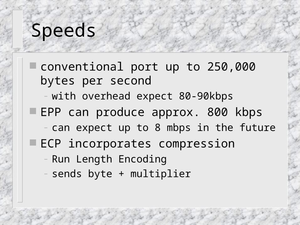
Speeds
conventional port up to 250,000 bytes per second– with overhead expect 80-90kbps
EPP can produce approx. 800 kbps– can expect up to 8 mbps in the future
ECP incorporates compression – Run Length Encoding– sends byte + multiplier

Assignment