eei~c - north dakota
TRANSCRIPT

EEI~C Energy & Environmental Research Center15 North 23rd Street, Stop 9018• Grand Forks, ND 58202-9018• P. 701.777.5000• F. 701.777.5181
www.undeerc.org
October 18, 2019
Ms. Karlene FineExecutive DirectorNorth Dakota Industrial CommissionState Capitol, 14th Floor600 East Boulevard Avenue, Department 405Bismarck, ND 58505-0840
Dear Ms. Fine:
Subject: EERC Final Report Entitled “Lightning Protection Scoping Study”Contract No. G-000-004; EERC Fund 24324
Attached please find the subject University of North Dakota (UND) Energy &Environmental Research Center (EERC) final report.
If you have any questions or comments, please contact me by phone at (701) 777-5293 orby e-mail at [email protected].
Sincerely,
Bradley G. StevensSenior Research EngineerCivil Engineering
BGS/kal
Attachment
c/att: Brent Brannan, NDIC
UNIVERSITY OT
LN)NORT[1 DAKOTA.

LIGHTNING PROTECTION SCOPING STUDY Final Report (for the period of August 28, 2019, through October 31, 2019) Prepared for: Karlene Fine North Dakota Industrial Commission State Capitol, 10th Floor 600 East Boulevard Avenue Bismarck, ND 58505-0310 Contract No. G-00-004
Prepared by:
Bradley G. Stevens Meghan A. Taunton
Parker R. Aube Kevin C. Connors Chad A. Wocken
John A. Harju
Energy & Environmental Research Center University of North Dakota
15 North 23rd Street, Stop 9018 Grand Forks, ND 58202-9018
2019-EERC-10-20 October 2019

EERC DISCLAIMER LEGAL NOTICE This research report was prepared by the Energy & Environmental
Research Center (EERC), an agency of the University of North Dakota, as an account of work sponsored by North Dakota Industrial Commission. Because of the research nature of the work performed, neither the EERC nor any of its employees makes any warranty, express or implied, or assumes any legal liability or responsibility for the accuracy, completeness, or usefulness of any information, apparatus, product, or process disclosed or represents that its use would not infringe privately owned rights. Reference herein to any specific commercial product, process, or service by trade name, trademark, manufacturer, or otherwise does not necessarily constitute or imply its endorsement or recommendation by the EERC.
NDIC DISCLAIMER This report was prepared by the Energy & Environmental Research Center (EERC) pursuant to an agreement partially funded by the Industrial Commission of North Dakota, and neither the EERC nor any of its subcontractors nor the North Dakota Industrial Commission nor any person acting on behalf of either:
(A) Makes any warranty or representation, express or implied, with respect to the accuracy, completeness, or usefulness of the information contained in this report or that the use of any information, apparatus, method, or process disclosed in this report may not infringe privately owned rights; or
(B) Assumes any liabilities with respect to the use of, or for damages resulting from the
use of, any information, apparatus, method, or process disclosed in this report. Reference herein to any specific commercial product, process, or service by trade name, trademark, manufacturer, or otherwise does not necessarily constitute or imply its endorsement, recommendation, or favoring by the North Dakota Industrial Commission. The views and opinions of authors expressed herein do not necessarily state or reflect those of the North Dakota Industrial Commission

i
TABLE OF CONTENTS
LIST OF FIGURES ....................................................................................................................... iii
LIST OF TABLES ......................................................................................................................... iii
DEFINITION OF TERMS ............................................................................................................ iv
1.0 INTRODUCTION ................................................................................................................. 1 1.1 Purpose of Scoping Study ............................................................................................ 1 1.2 Personal Communication ............................................................................................. 1 1.3 Lightning Statistics in the Williston Basin .................................................................. 1
2.0 SCIENCE OF LIGHTNING AND STATIC ELECTRICITY .............................................. 3 2.1 Charged Particles and Their Properties ....................................................................... 3 2.2 Charging Mechanisms ................................................................................................. 3 2.3 Lightning ...................................................................................................................... 4 2.4 Static Electricity ........................................................................................................... 6
3.0 FACILITY OPERATIONS ................................................................................................... 6 3.1 Saltwater Disposal ....................................................................................................... 6 3.2 Oil Production .............................................................................................................. 7
4.0 SUMMARY OF APPLICABLE LIGHTNING PROTECTION STANDARDS ................. 7 4.1 National Fire Protection Association ........................................................................... 8
4.1.1 NFPA 780 – Standard for the Installation of Lightning Protection Systems ............................................................................................................ 8
4.1.2 NFPA 77 – Recommended Practice on Static Electricity ............................... 8 4.2 American Petroleum Institute ...................................................................................... 9
4.2.1 API 2003 – Recommended Practice for Protection Against Ignitions Arising Out of Static, Lightning, and Stray Currents ...................................... 9
4.2.2 API RP 545 – Recommended Practice for Lightning Protection of Aboveground Storage Tanks for Flammable or Combustible Liquids ............ 9
4.3 International Electrotechnical Commission ................................................................. 9 4.3.1 IEC 62305 – International Standard for Lightning Protection ........................ 9
5.0 PRINCIPLES OF LIGHTNING PROTECTION ............................................................... 10 5.1 Current Diversion ...................................................................................................... 10 5.2 Surge Protection ......................................................................................................... 10
6.0 STORAGE TANKS ............................................................................................................ 10
7.0 LIGHTNING PROTECTION SYSTEMS .......................................................................... 11 7.1 Components of Traditional Lightning Protection Systems ....................................... 11
7.1.1 Air Terminals ................................................................................................. 11
Continued . . .

ii
TABLE OF CONTENTS (continued)
7.1.2 Down-Conductors .......................................................................................... 12 7.1.3 Grounding Electrode ...................................................................................... 13 7.1.4 Bonding.......................................................................................................... 13
7.2 Nontraditional Types of Lightning Protection Systems ............................................ 13 7.2.1 CTSs .............................................................................................................. 13 7.2.2 ESE Systems .................................................................................................. 14 7.2.3 Other Nontraditional Lightning Protection .................................................... 15 7.2.4 In-Tank Static Dissipaters .............................................................................. 15 7.2.5 Electromagnetic Shielding ............................................................................. 16
8.0 REVIEW OF REGULATORY AND INSURANCE REQUIREMENTS FOR LIGHTNING PROTECTION ............................................................................................. 16 8.1 Regulatory Discussion ............................................................................................... 16 8.2 Insurance Discussion ................................................................................................. 17
9.0 KEY FINDINGS ................................................................................................................. 17
10.0 NEXT STEPS ...................................................................................................................... 18 10.1 State-Specific Activities ............................................................................................ 18 10.2 Research Activities .................................................................................................... 18
11.0 REFERENCES .................................................................................................................... 19
iii
LIST OF FIGURES
1 Lightning strike/spill locations by year ................................................................................. 2
2 Propagation of a lightning stroke .......................................................................................... 5
3 Example of traditional air terminals .................................................................................... 12
4 Example of CTS air terminal .............................................................................................. 13
5 Examples of ESE air terminals ............................................................................................ 14
6 CMCE-55 ............................................................................................................................ 15
7 Example of in-tank static dissipater .................................................................................... 15
8 Example of EM shielding system ........................................................................................ 16
LIST OF TABLES
1 Summary of Lightning Strike Data ....................................................................................... 3

iv
DEFINITION OF TERMS Air terminal: A lightning strike termination device installed as part of a lightning protection system designed to intentionally attract lightning. Also called a lightning rod or Franklin rod. Bonding: An electrical connection between components of a lightning protection system. Also describes the act of electrically connecting a lightning protection system with other conductive elements on-site, such as building piping and wiring. Charge polarization: Charge polarization occurs when the charge distribution in an object becomes separated, so that the net charge on the object is still the same but the positive and negative charges are congregated in opposite directions from each other. This causes the charge density of certain areas of the object to change. Current transfer system (CTS): A broad term used to describe several devices including dissipation array systems, spine ball ionizers, and spine ball terminals. CTS is intended to prevent a lightning strike from occurring within a protected zone. In theory, the CTS “collects” the induced charge created by a thunderstorm and transfers the charge into the surrounding air. Down-conductor: A component of the lightning protection system intended to carry the lightning current from the air terminal to the grounding electrode. Early streamer emission (ESE) system: ESE systems are similar to conventional lightning protection systems except that they employ air terminals that, according to their proponents, launch an upward-connecting leader to meet the descending-stepped leader at an earlier time than would a conventional air terminal having similar geometry and installed at the same height. Grounding electrode: A component of the lightning protection system extending into the earth. May be in the form of a ground rod, ground plate, ground grid, or some combination of conductors in the earth. Grounding: The practice of electrically connecting devices, structures, or vessels to the earth. Lightning protection system: A system designed to protect structures from damage as a result of lightning strikes. Main components include air terminals, down conductors, and grounding electrodes. Static: The buildup of electrical charge on a structure or vessel or in a fluid. Static can accumulate from fluids moving in pipes, filling and pumping down tanks, or dust blowing across a surface, to name a few. Static dissipation: The act of “bleeding off” static that has accumulated. Accomplished by connecting structure, device, vessel, or fluid to a grounding electrode.

v
Step leader: The initial propagation of multiple lightning leaders from the base of a thunderstorm cloud toward the earth. Up-streamer: The charged ionic channel that emanates upward from the earth to meet the step leaders coming down from the cloud.

1
LIGHTNING PROTECTION SCOPING STUDY 1.0 INTRODUCTION The North Dakota Industrial Commission (NDIC), in an effort to better understand lightning and its impacts on oil and gas facilities, funded the Energy & Environmental Research Center (EERC) to compile relevant information and report it to NDIC in the form of a scoping study. This report defines the science of lightning strikes and static potential, identifies and defines grounding and bonding standards associated with lightning protection, reviews available lightning protection technology, and provides information about spill incidents attributed to lightning strikes from operators, regulators, and subject matter experts.
1.1 Purpose of Scoping Study The purpose of the scoping study was to develop an understanding of the cause of lightning strikes at saltwater disposal (SWD) and oil production facilities in the Williston Basin through information gathered from facility operators, lightning protection companies, regulators, and subject matter experts.
1.2 Personal Communication The EERC communicated with many individuals who had either firsthand information about lightning strike incidents, were subject matter experts on lightning and static phenomena, or were offering a component or service related to lighting protection. These personal communications significantly contributed to the content of this report. Specifically, information was gathered from individuals from the following groups:
• Oil production and SWD facility operators • Lightning protection equipment vendors • Fiberglass and steel tank manufacturers • North Dakota state regulators • Insurance companies • Lightning and static science subject matter experts
1.3 Lightning Statistics in the Williston Basin
A review of the North Dakota Department of Mineral Resources (NDDMR) database indicated that from 2014 to 2019, the number of oil production and SWD wells increased from 10,732 to 15,073 and from 448 to 465, respectively. Although the exact number was not determined, it is certain that this increase in wells has resulted in an increase in associated facilities (specifically tank batteries).

2
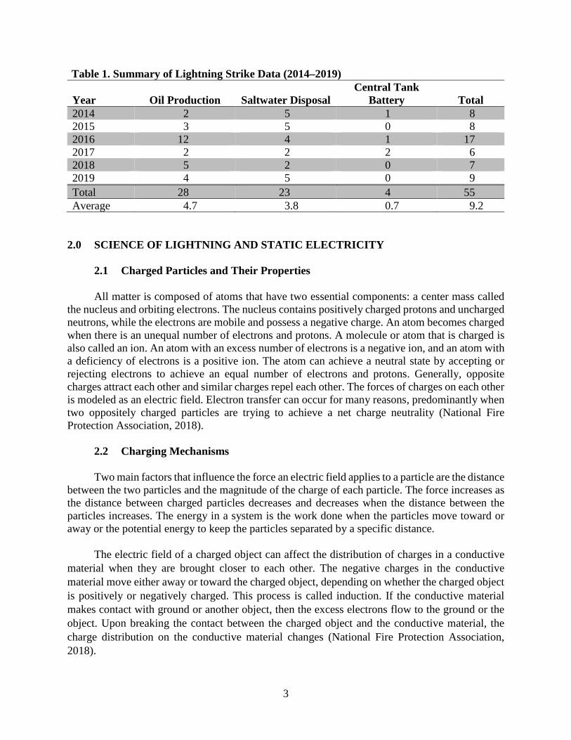
Spill report information from lightning-related facility failures was provided by NDDMR. The data were generated from spill reports between 2014 and 2019 that reported lightning as the root cause. Data indicate that over this 6-year period, 55 lightning-caused spills were reported at oil production facilities (28), SWD facilities (23), and central tank batteries (4). Figure 1 shows the location of the 55 lightning strike-related spills by year, and Table 1 summarizes the information by year and type of facility. A published study looked at 242 tank accidents over a 40-year period and found that lightning was the most frequent cause of accident (33%), followed by maintenance (13%) and operational error (12%) (Chang and Lin, 2006). It should be noted that only lightning strikes that resulted in a spill report are discussed in this report. It is plausible that lightning strikes at facilities or structures that did not result in a spill would not have been reported; therefore, no public data would be available.
Figure 1. Lightning strike/spill locations by year (central tank battery strikes not included).
3
Table 1. Summary of Lightning Strike Data (2014–2019)
Year Oil Production Saltwater Disposal Central Tank
Battery Total 2014 2 5 1 8 2015 3 5 0 8 2016 12 4 1 17 2017 2 2 2 6 2018 5 2 0 7 2019 4 5 0 9 Total 28 23 4 55 Average 4.7 3.8 0.7 9.2
2.0 SCIENCE OF LIGHTNING AND STATIC ELECTRICITY
2.1 Charged Particles and Their Properties All matter is composed of atoms that have two essential components: a center mass called the nucleus and orbiting electrons. The nucleus contains positively charged protons and uncharged neutrons, while the electrons are mobile and possess a negative charge. An atom becomes charged when there is an unequal number of electrons and protons. A molecule or atom that is charged is also called an ion. An atom with an excess number of electrons is a negative ion, and an atom with a deficiency of electrons is a positive ion. The atom can achieve a neutral state by accepting or rejecting electrons to achieve an equal number of electrons and protons. Generally, opposite charges attract each other and similar charges repel each other. The forces of charges on each other is modeled as an electric field. Electron transfer can occur for many reasons, predominantly when two oppositely charged particles are trying to achieve a net charge neutrality (National Fire Protection Association, 2018).
2.2 Charging Mechanisms Two main factors that influence the force an electric field applies to a particle are the distance between the two particles and the magnitude of the charge of each particle. The force increases as the distance between charged particles decreases and decreases when the distance between the particles increases. The energy in a system is the work done when the particles move toward or away or the potential energy to keep the particles separated by a specific distance. The electric field of a charged object can affect the distribution of charges in a conductive material when they are brought closer to each other. The negative charges in the conductive material move either away or toward the charged object, depending on whether the charged object is positively or negatively charged. This process is called induction. If the conductive material makes contact with ground or another object, then the excess electrons flow to the ground or the object. Upon breaking the contact between the charged object and the conductive material, the charge distribution on the conductive material changes (National Fire Protection Association, 2018).

4
Friction (triboelectric charging) is a common way for objects to become charged. When multiple objects are in contact with one another, there is a transfer of free electrons among the objects. However, depending on the resistivity of the materials the electrons may not be able to associate with equal amounts of positive charges. If the objects are then removed from each other, there will be an unequal distribution of charges among the different objects. This effect can happen on any type of material, including fluids. Charge polarization occurs when the charge distribution in an object becomes separated so that the net charge on the object is still the same but the positive and negative charges are congregated in opposite directions from each other. This causes the charge density of certain areas of the object to change. An object’s charge distribution is affected by several factors, one being the geometry of the object. Sharp corners and narrow points (i.e., corners of buildings and points of lightning rods) tend to have higher charge densities, due to like charges in the object repelling each other in limited space.
2.3 Lightning Lightning is an electric phenomenon in which charges accumulated in the cloud will be discharged into neighboring clouds or to the ground. There are many factors that influence the accumulation of charges in the clouds. During a thunderstorm, the positive and negative charges in the cloud become separated by the turbulent winds that carry ice and water particles. These particles vary in size and mass, which causes charge separation in clouds. During the turbulent movement of wind, these water particles collide with each other, resulting in a triboelectric effect among those particles. As a result, the electrons are stripped off the particles, and these electrons gather at the lower section of the cloud, whereas the protons move up. Because of electromagnetism, the charge that develops in the lower portion of a cloud (most often negative) induces an opposite or positive charge on Earth’s crust. As the storm moves over Earth’s surface, the area of the induced charge changes, causing a small current to flow on Earth’s surface. The phenomenon of lightning occurs when atmospheric conditions permit the transfer of charges among ionized atmospheric particles to the ground. This transfer momentarily neutralizes the electric field by the attachment point of the lightning stroke. Lightning can be of different forms and can transfer different kinds of charges. The most common kind of lightning strike is cloud-to-ground, where negatively charged leaders are produced and travel through the air in a path that has the least amount of resistance to the ground. Before the leader reaches Earth’s surface an upward streamer is commonly produced, which will protrude from Earth’s surface and connect with the downward leader from the cloud. The lightning bolt that propagates from a cloud is made up of multiple step leaders. Each leader has a very strong electric field, which can produce a corona discharge (American Petroleum Institute, 2003). The corona discharge occurs when there is a high voltage between a sharp, pointed object and a neutral reference point (National Fire Protection Association, 2018). It is capable of breaking down gases and ionizing nearby particles, ultimately aiding a leader step to creating a path for the next leader step. As the step leader gets closer to ground, the electric field on Earth’s surface below the step leader rises rapidly. The induced electric field, in some circumstances, can
5
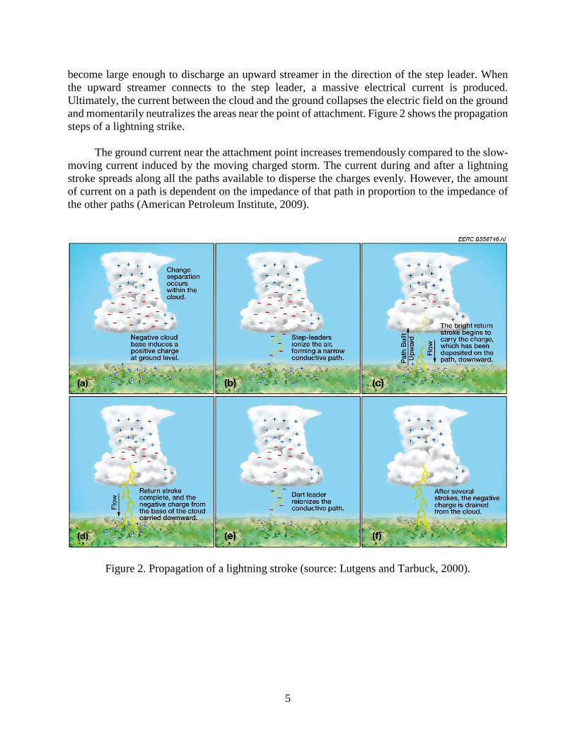
become large enough to discharge an upward streamer in the direction of the step leader. When the upward streamer connects to the step leader, a massive electrical current is produced. Ultimately, the current between the cloud and the ground collapses the electric field on the ground and momentarily neutralizes the areas near the point of attachment. Figure 2 shows the propagation steps of a lightning strike. The ground current near the attachment point increases tremendously compared to the slow-moving current induced by the moving charged storm. The current during and after a lightning stroke spreads along all the paths available to disperse the charges evenly. However, the amount of current on a path is dependent on the impedance of that path in proportion to the impedance of the other paths (American Petroleum Institute, 2009).
Figure 2. Propagation of a lightning stroke (source: Lutgens and Tarbuck, 2000).

6
2.4 Static Electricity Static electricity can accumulate through charging mechanisms, which were previously discussed in the Section 2.2 Charging Mechanisms. Charge retention is an object’s ability to keep its accumulated charge from dissipating to other parts of its environment. The atmospheric conditions (humidity) surrounding charged objects have a major effect on their ability to drain their charge over time. Other factors that affect an object’s charge retention include the conductivity of the material and the materials it is in contact with, as well as temperature, atmospheric pressure, and the object’s shape (Institute of Electrical and Electronics Engineers, 1993). Conductive materials (conductors) allow charges to easily move through the material and transfer to other materials. Nonconductors (insulators) have the opposite effect on charges. The humidity of the relative environment of an object will significantly affect the object’s charge retention depending on whether the object’s material is a conductor or an insulator. Higher humidity will increase conductivity, i.e., decreasing the charge retention, of a conductor. However, insulators will be less affected by these environmental conditions, making them able to hold onto their charge until another variable is introduced into the system. An electrostatic discharge (ESD) occurs when two electrically charged objects come in contact, which allows for the transfer of charges between these objects under certain atmospheric and geometric conditions. This may cause an illuminated arc between the air gap of the two objects. The arc will contain a portion of the total amount of energy stored in the charged system (Institute of Electrical and Electronics Engineers, 1993). 3.0 FACILITY OPERATIONS Understanding the operational function of both SWD and oil production facilities is important since normal operating conditions have the potential to influence static buildup and/or the likelihood of lightning strikes. In general, the movement of fluid within a tank during filling and emptying operations can induce a static charge on the vessel. This static charge can dissipate with time to ground through dedicated grounding systems or the tank and piping. If not dissipated, this static charge can produce an electrical potential that can lead to a spark and subsequent ignition of flammable vapors or contribute to a lightning strike, as lightning seeks the lowest resistance path to ground. A summary of typical tank-loading operations and measures used to minimize static discharge is provided below.
3.1 Saltwater Disposal Saltwater, also called produced water or brine, is a natural part of oil and gas production and SWD facilities are a required component of infrastructure to dispose of this fluid. Fluid will arrive on-site by pipeline or truck.

7
Underground gathering pipelines for saltwater are generally constructed of nonmetallic pipe and connected directly to a storage tank. The saltwater travels from the oil and gas operator’s production facility directly to the SWD facility, which may be several miles away. Trucks arrive on-site and a retractable grounding device or wire is attached to the unloading pod or dedicated ground rod. The truck is hooked up to the tank battery with a flexible hose to a metal quick coupling inside the pod. Once this is complete, the truck begins unloading fluid, passing through a filter pod, and ultimately ending in a fiberglass storage tank prior to injection. Prior to unhooking the flexible hose, a vacuum must be applied to the hose to remove any fluid left inside. The final step is to remove the retractable grounding wire from the pod prior to leaving the site. The tanks used at SWD facilities are typically constructed of fiberglass, although some operators have chosen to utilize epoxy-lined steel tanks for a variety of reasons. Fiberglass tanks are preferred because of their resistance to the corrosivity of the produced water.
3.2 Oil Production Oil production facilities serve a different purpose. A mixture of oil, water, and gas is pumped from the well to one or more vessels designed to separate the three components. The gas is transported via pipeline to a gas-processing facility. The oil is typically stored on-site in steel tanks and/or transported through a steel flowline/pipeline via a lease automatic custody transfer (LACT) system. As with SWD facilities, the produced water is typically stored on-site in fiberglass tanks and/or transported through a nonmetallic gathering pipeline or tanker truck to a SWD facility. When truck transport is required, trucks arrive on-site and attach a retractable grounding device or wire to the unloading pod or dedicated ground rod. A flexible hose is used to connect the tanker truck to a metal quick coupling inside the loading pod of the storage tank battery. Once this is complete, the truck begins loading fluid (oil or produced water). Prior to unhooking the flexible hose, a vacuum must be applied to the hose to remove any fluid left inside. The final step is to remove the retractable grounding wire from the loading pod prior to leaving the site. The truck transports the fluid to either a SWD or an oil-unloading facility. 4.0 SUMMARY OF APPLICABLE LIGHTNING PROTECTION STANDARDS Several organizations have published standards and guidance related to lightning protection systems and static electricity. In the United States, the National Fire Protection Association (NFPA) (2017) is most frequently identified as the governing agency for lightning protection systems. The American Petroleum Institute (API) has also published guidance documents related to lightning protection in the oil and gas industry. The most widely recognized international standard for protection against lighting is International Electrotechnical Commission (IEC) Standard 62305. A brief summary of these standards and guidance documents is provided here.

8
4.1 National Fire Protection Association
4.1.1 NFPA 780 – Standard for the Installation of Lightning Protection Systems NFPA 780 is an industry-recognized standard practice for design and installation of traditional lightning protection systems. This standard is the best-known source of information regarding lightning protection system design, providing the philosophy behind traditional lightning protection systems. However, it specifically states that it does not cover installation requirements for nontraditional lightning protection systems such as early streamer emission (ESE) and current transfer systems (CTS). NFPA 780 was developed to safeguard persons and property from fire risks and related hazards arising from exposure to lightning. NFPA 780 specifies lightning protection system installation requirements for structures containing flammable vapors, flammable gases, or liquids that can give off flammable vapors. The standard states, in part, “a primary means to reduce ignition of flammable vapors shall be to minimize the presence of those vapors in places that are vulnerable to a source of ignition such as heating, arcing, or corona discharge caused by one of the following: 1) a direct strike, 2) lightning electromagnetic pulse (LEMP), or 3) secondary arcing” (National Fire Protection Association, 2017). NFPA 780, Annex N, specifically addresses nonmetallic tanks containing flammable vapors, flammable gases, or liquids that can give off flammable vapors. Annex N states, “The protection of nonmetallic tanks that might contain flammable vapors, flammable gases, or liquids that can give off flammable vapors requires measures above and beyond protection of other structures discussed in this standard. It is recommended that nonmetallic tanks not be used in applications where flammable vapors might be present. The recommendations in this annex are provided to identify methods that can be used to mitigate, but not eliminate, lightning-related damage” (National Fire Protection Association, 2017).
4.1.2 NFPA 77 – Recommended Practice on Static Electricity NFPA 77 is a recommended practice to identify, assess, and control static electricity for the purpose of preventing fires and explosions. NFPA 77 addresses the potential hazards that arise when static electricity is generated, accumulates, and discharges. This standard specifically addresses storage tanks with flammable and combustible liquids and their vapors. NFPA 77 states, “Liquid flowing into a tank can carry a static electric charge that will accumulate in the tank. This charge can be detected as a potential above the surface of the liquid in the tank. The maximum surface potential attained depends not only on the charge density of the incoming liquid but also on the dimensions of the tank” (National Fire Protection Association, 2018). This standard provides guidance on precautions to be taken related to storage tanks with flammable and combustible liquids. The standard also offers techniques for controlling the hazards of static electricity.

9
4.2 American Petroleum Institute
4.2.1 API 2003 – Recommended Practice for Protection Against Ignitions Arising Out of Static, Lightning, and Stray Currents
API Recommended Practice (RP) 2003 is a recommended practice for the petroleum industry to prevent hydrocarbon ignition from static electricity, lightning, and stray currents. RP 2003 offers the current state of knowledge and technology regrading oil and gas industry applications for protection against ignitions arising out of static, lightning, and stray currents. The principles discussed in this recommended practice are applicable to other operations where ignitable liquids and gases are handled. Their use should lead to improved safety practices and evaluations of existing installations and procedures. RP 2003 specifically addresses fiberglass tanks stating, “It is not recommended to store flammable liquids in nonconductive (e.g., plastic, fiberglass) aboveground tanks” (American Petroleum Institute, 2003). The recommended practice further describes concerns relating to electrostatic accumulation, “When nonconductive tanks are used for hydrocarbon storage or storage of materials that may be contaminated with flammable products, significant electrostatic concerns are introduced” (American Petroleum Institute, 2003). The recommended practice provides guidance to ensure the safe dissipation of charges and how to prevent discharges.
4.2.2 API RP 545 – Recommended Practice for Lightning Protection of Aboveground Storage Tanks for Flammable or Combustible Liquids
API RP 545 provides guidance and information on lightning protection for tanks. This recommended practice replaces the requirements of API RP 2003 regarding lightning protection for preventing fires in storage tanks with flammable or combustible contents. This standard applies to new tanks and may also be applied to existing tanks. This recommended practice is a first edition published in October 2009. API RP 545 is intended for manufacturers of welded steel oil storage tanks of various sizes and capacities. The standard addresses protections for fixed-roof metallic tanks and tanks with either internal or external floating roofs. This recommended practice includes information related to lightning principles and the effects of a direct or indirect lightning stroke on a tank containing flammable and combustible liquids. In addition, it also provides guidance on lightning protection, maintenance, and inspection of aboveground oil storage tanks.
4.3 International Electrotechnical Commission
4.3.1 IEC 62305 – International Standard for Lightning Protection IEC 62305 is an international standard for lightning protection systems. This standard consists of four main parts: general principles, risk management, physical damage to structures and life hazard, and electrical and electronic systems within structures. This standard comprises a methodology for assessing risk and guidance based on lightning protection levels to address the risks identified. IEC 62305 describes four levels of a lightning protection system based on the

10
characteristics of an anticipated lightning stroke. Each level has four corresponding classes that are defined and make up specific construction rules. The lightning protection levels are assigned values which, in turn, are used to determine the construction requirements for the lightning protection system. 5.0 PRINCIPLES OF LIGHTNING PROTECTION The purpose of lightning protection is to provide a pathway for lightning-induced electrical current or electromagnetic field to pass through a facility without damaging equipment, creating arcs or spark, and thereby preventing damage. Systems are designed to protect facilities against lightning striking the facility itself (direct lightning strike) and from indirect strikes in which current can travel through conductors such as pipes or cables (electrical, communication) into a facility. Adequate lighting protection systems include current diversion and surge protection. While these two factors are related, they are often treated separately in codes and standards (Uman, 2008).
5.1 Current Diversion Current diversion is the rerouting of the lightning current away from the protected structure and into the earth (Uman, 2008). A current diversion system is composed of three electrically connected components; air terminals, down-conductors, and grounding electrodes.
5.2 Surge Protection Surge protection is a necessary component of a complete lightning protection system and is designed to protect electrical, communications, and antenna systems from:
• The voltages induced in those electrical and electronic systems due to the flow of lightning current in the lightning protection system and the electromagnetic effects of lightning in close proximity to the protection system.
• The lightning-induced voltages on the structure via incoming power feeders and
data/communication lines, given that these utility lines may have relatively large voltages induced on them by direct or nearby strikes.
Recommendations for surge protection are outlined in NFPA 780 and IEC 62305 and vary depending on the specifics of the facility (Brandon, 2018). 6.0 STORAGE TANKS Storage tanks containing low conductive liquids can accumulate static charge through any type of flow of the liquid within them. The motion of the liquid causes a triboelectric effect among the inner surface of the tank and the liquid itself. In addition, a static charge can accumulate on a tank from wind blowing dust or other particles across the outside of the tank. The static charge

11
accumulation between the tank and contents of the tank can cause an ignition hazard, depending on the minimum ignition energy (MIE) of the contents of the tank. The potential electrical energy can decay over time when the charge transfer occurs through a path of resistance. The rate at which the energy is dissipated is affected by many factors, including the conductivity of the materials, geometry of the objects’ shapes, and atmospheric conditions. A massive electric field such as a thunderstorm can induce and affect the charge distribution of a tank, causing a spark across air gaps as the charge densities change between the tank and its contents. Tanks are also at risk of direct and indirect lightning strikes. For direct lighting strikes, the height and resistive properties of a tank material make a preferable path to ground during a thunderstorm rather than a flat area that is farther away from the approaching leader step. The leader step will make contact on the tank at locations of least resistance and greatest potential, primarily the highest points of the tank. Tank designs vary but the most common contact points are handrails, gas/pressure vents, and other equipment on top of the tank, from which the current will spread across all paths to ground. If there are any air gaps along a path, there is a possibility that current will arc across the gap, depending on the potential and resistance of that path. The arcs between air gaps may ignite a tank’s contents, depending on the energy of the arc and the MIE of the contents of the tank. As discussed above, the current of a lightning stroke spreads proportionally along all its paths of dispersion. If a tank is within a path of current from an indirect stroke, then the current can possibly arc over any air gaps on the tank. However, the energy of an arc over an air gap from an indirect lightning stroke is most often considerably less than the energy from a direct lightning stroke (American Petroleum Institute, 2009). 7.0 LIGHTNING PROTECTION SYSTEMS For the purposes of this report, lightning protection systems are categorized in two ways: traditional and nontraditional. Traditional systems are designed to perform as current diversion systems by using air terminals, down-conductors, and grounding electrodes and include consideration for adequate bonding and surge protection. Nontraditional systems describe all other systems, including CTSs and ESE systems. Nontraditional lightning protection systems are based on either preventing lightning from striking or improving the effectiveness of directing lightning to ground without causing damage.
7.1 Components of Traditional Lightning Protection Systems
7.1.1 Air Terminals Air terminals (also known as Franklin rods), are vertical rods or catenary and meshed wires (or other conductor, as described in NFPA 780 and IEC 62305) connected together on top of or above a structure to intercept the descending lightning stepped leader (Uman, 2008). Benjamin Franklin first described the concept in the year 1753. The traditional Franklin rod is a sharp-pointed rod but is often used to describe any vertical lightning rod (Uman, 2008). While the guiding principles were clear and elucidated by Franklin, the details regarding the optimal geometry of

12
lightning rods (i.e., length, diameter, curvature of tip) and the overall design of lightning protection systems have been widely debated throughout the industry and international scientific community. The placement of the air terminals on and around the structures create zones of protection to protect the structure from direct and indirect lightning strikes. Calculation methods used to determine the zone of protection are included in both NFPA 780 and IEC 62305 (Brandon, 2018). A conventional air terminal lightning protection system, as described by API RP 2003, consists of installing a suitable number of air terminals (also called lightning rods), conducting masts or overhead shield wires above the structures or areas to be protected. These devices are bonded to the grounding system. The air terminals, masts, or shield wires are designed to collect incoming lightning strikes by generating upward streamers. Installation requirements and specific information about the protected zone can be found in NFPA 780. Conventional air terminal lightning protection systems do not protect against indirect lightning currents or induced voltages. These effects are addressed by proper bonding and the application of surge protection devices (American Petroleum Institute 2003, Appendix C). Figure 3 shows a typical air terminal in a traditional lightning protection system.
Figure 3. Example of traditional air terminals.
7.1.2 Down-Conductors Down-conductors are designed to carry the lightning current downward safely into the earth termination system while also limiting the risk of flashover to other electrically conductive elements (Brandon, 2018). The down-conductors are connected to the air terminals and placed along the perimeter of a structure. Both NFPA and IEC standards require a minimum of at least two down-conductors for each structure, but the requirement for the spacing between conductors varies between standards. NFPA 780 states the average distance between conductors should not exceed 30 meters while IEC 62305 specifies the conductors be arranged in such a way as to reduce

13
the probability of damage due to lightning current flowing in the lightning protection system (Brandon, 2018).
7.1.3 Grounding Electrode (earth termination system) The earth termination system serves to properly bond and ground the electrically conductive current generated from the lightning surge into the down-conductors away from the structure and into the earth (Brandon, 2018). The design of the earth termination system may comprise a bonded system of earth electrodes or a ring conductor encircling the structure being protected. Both designs are specified in NFPA 780 and IEC 62305 standards. The NFPA 780 earth termination system is dimensioned and designed per applicable clauses, while the earth electrode and ring conductor designs, as described in IEC 62305-3, are based on the class of lightning protection system (Brandon, 2018).
7.1.4 Bonding Bonding is a term used to describe the interconnecting of the components of the lightning protection system to other conductive components to preclude voltage differences. If present, this may include bonding the lightning protection system to internal conductive components of buildings such as water, sewer, and gas piping, resulting in all localized grounding having the same potential. Appropriate bonding helps to reduce differences in electrical potential and the likelihood of flashover or sparking as current seeks the lowest resistance path to ground.
7.2 Nontraditional Types of Lightning Protection Systems Nontraditional lightning protection systems are commercially available and typically have propriety configurations and/or components. These nontraditional technologies generally fall into two categories: CTSs and ESE systems.
7.2.1 CTSs
API RP 2003 describes this type of lightning protection as a charge transfer, ionizing, or streamer-delaying lightning protection system. CTS consists of installing a suitable number of ionizers or ionizing air terminals above the structures or areas to be protected (Figure 4). These devices are then bonded to the grounding system. The ionizers and ionizing air terminals are designed to 1) establish a conductive path for the step leader and 2) suppress or delay the formation of upward streamers. Installation requirements and specific information about the protected zone are available from the systems’ manufacturers. The charge transfer, ionizing, or streamer-delaying systems may have some benefit in reducing indirect lightning currents or induced voltages. However, proper bonding and surge protection devices should still be provided (American Petroleum Institute, 2003, Appendix C).
Figure 4. Example of CTS air terminal (source: Lightning Eliminators).

14
7.2.2 ESE Systems ESE systems are similar to conventional lightning protection systems except that they employ air terminals that, according to their proponents, launch an upward-connecting leader to meet the descending-stepped leader at an earlier time than would a conventional air terminal having similar geometry and installed at the same height. This earlier-initiated upward-connecting leader is claimed to be capable of extending significantly longer distances and, as a result, provides a significantly larger zone of protection than the upward-connecting leader from a conventional air terminal of the same height (Uman, 2008; Uman and Rakov, 2002). An ESE air terminal lightning protection system consists of a suitable number of ESE air terminals installed above the structures or areas to be protected. These devices are bonded to the grounding system similarly to traditional lightning protection systems. ESE air terminals are designed to generate upward streamers that launch sooner than conventional lightning rods, thus providing a more attractive point of termination. Installation requirements and specific information about the protected zone are available from the systems’ manufacturers. ESE air terminal lightning protection systems do not protect against indirect lightning currents or induced voltages. These effects are addressed by proper bonding and the application of surge protection devices (American Petroleum Institute, 2003). Figure 5 depicts several examples of ESE air terminals.
Figure 5. Examples of ESE air terminals (modified image from Rizk, 2019).

15
7.2.3 Other Nontraditional Lightning Protection Certain devices on the market do not necessarily fit the previous two classes of nontraditional lightning protection. Although there may be others, our research found one EMP Solutions’ CMCE-55, and it is based on the principle of balancing positive and negative ions and sending them to ground before a cloud to ground strike has a chance to form. The claim is that this results in a large protected area where lightning will not strike (EMP Solutions, 2019). Figure 6 shows the EMP Solutions device.
7.2.4 In-Tank Static Dissipaters In-tank static dissipation devices are used to divert static charge buildup occurring inside nonmetal or steel crude oil and saltwater storage tanks. Static charges can accumulate and remain in the tank until they are able to move through an electric current or electrical discharge. The internal tank dissipation technology utilizes a low-conductivity material grounded to the tank or some other component of the grounding network. As static electricity builds inside the tank, the low-conductivity material allows a pathway for the static charges to slowly and safely exit the tank without a sudden electrical discharge that has the potential to ignite vapors and combustible liquids stored in the tank. Figure 7 shows an example of an in-tank static dissipater.
Figure 6. CMCE-55. (source: EMP Solutions).
Figure 7. Example of in-tank static dissipater (source: Lightning Master Corporation).
16
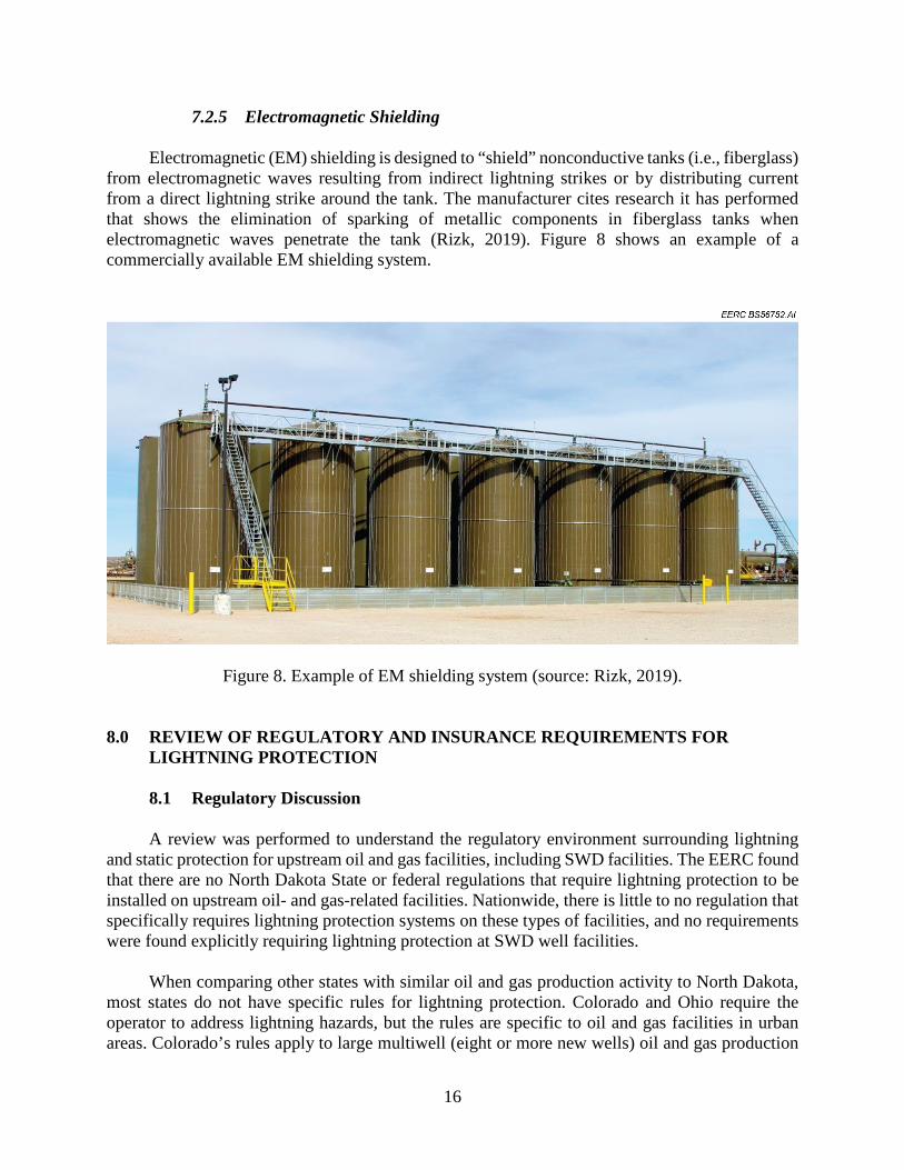
7.2.5 Electromagnetic Shielding Electromagnetic (EM) shielding is designed to “shield” nonconductive tanks (i.e., fiberglass) from electromagnetic waves resulting from indirect lightning strikes or by distributing current from a direct lightning strike around the tank. The manufacturer cites research it has performed that shows the elimination of sparking of metallic components in fiberglass tanks when electromagnetic waves penetrate the tank (Rizk, 2019). Figure 8 shows an example of a commercially available EM shielding system.
Figure 8. Example of EM shielding system (source: Rizk, 2019). 8.0 REVIEW OF REGULATORY AND INSURANCE REQUIREMENTS FOR
LIGHTNING PROTECTION
8.1 Regulatory Discussion A review was performed to understand the regulatory environment surrounding lightning and static protection for upstream oil and gas facilities, including SWD facilities. The EERC found that there are no North Dakota State or federal regulations that require lightning protection to be installed on upstream oil- and gas-related facilities. Nationwide, there is little to no regulation that specifically requires lightning protection systems on these types of facilities, and no requirements were found explicitly requiring lightning protection at SWD well facilities. When comparing other states with similar oil and gas production activity to North Dakota, most states do not have specific rules for lightning protection. Colorado and Ohio require the operator to address lightning hazards, but the rules are specific to oil and gas facilities in urban areas. Colorado’s rules apply to large multiwell (eight or more new wells) oil and gas production

17
facilities with storage capacity greater than 4000 barrels per day in an area with 22 building units or one high-occupancy building unit within a 1000-ft radius of the proposed location (i.e., urban mitigation areas). Ohio requires each oil storage tank located in urbanized areas to have a functioning lightning arrestor. Ohio defines an urbanized area as a municipal corporation or a township that has an unincorporated population of more than 5000 people. The Pennsylvania Department of Environmental Protection Tanks Program provides a guidance document for oil and gas operators that highlights frequently used storage tank standards and practices for constructing, inspecting, and maintaining tanks on oil and gas facilities. This guidance document is not a requirement. The guidance includes reference to API RP 2003 Protection Against Ignitions Arising Out of Static, Lightning, and Stray Currents. The regulatory review found that most oil- and gas-producing states including North Dakota have specific sections in their administrative rules that address safety regulations for upstream oil-and gas-related facilities. These safety regulations almost always include addressing wellsite fire hazards, although the focus is typically on the location of heating equipment to the wellhead or oil tanks and the removal of combustible materials such as debris, not weather-related events. These requirements that appear to be standard among oil- and gas-producing states are in place to limit the potential of a fire occurring at an oil and gas production facility.
8.2 Insurance Discussion The EERC identified no information indicating that insurance companies are requiring facility operators to install lightning protection. As stated by Mr. Pat Nickodemus of Empire Company (Personal communication, October 2019), a large majority of oil and gas companies typically self-insure first-party property losses at oil production and SWD facilities where a lightning-caused fire might occur. Based on these facts, the EERC has concluded that decisions on whether to install lightning protection and what standards to follow if lightning protection is installed are dictated by individual corporate policies. 9.0 KEY FINDINGS Lightning is a natural phenomenon, and the factors influencing lightning strikes may not be fully understood, especially relating to oil and gas facilities. Accordingly, there is a lack of peer-reviewed research literature (Ewing et al., 2005). Although not required, when lightning protection equipment is installed, it appears that this is done based on corporate policy. NFPA 780 is the most appropriate standard to follow. Lightning protection experts suggest systems be installed and properly maintained by a qualified contractor using only Underwriters Laboratory-listed materials rated for lightning service (Underwriters Laboratory, 2016).

18
Incidents of lightning strikes resulting in spills do not appear to be increasing with the growing number of oil- and gas-related facilities. It is important to note that publicly available data are only available for lightning strikes that resulted in a spill. Lightning may strike an oil and gas facility, and if the current travels to ground, no damage to the facility may be observed. Lightning occurs in order to equalize differences in electrical charge (potential) between a storm and the earth. Tall objects and objects with an electrical or static charge are more likely to be struck as lightning seeks the easiest path to ground. Both fiberglass and steel tanks can accumulate a static charge as a result of operations or environmental conditions making them susceptible to a lightning strike. Although NFPA 780 recommends fiberglass tanks not be used in applications where flammable vapors might be present, the EERC found no peer-reviewed scientific data specifically citing tank material as the only factor influencing failure due to lightning strikes. Although lightning is the primary focus of the scoping study, the role of static charge cannot be overlooked as a potential contributor. Lightning protection technologies fall in to two general categories: traditional and nontraditional. Both categories utilize many similar components including electrical conductive cables and grounding systems. Only traditional lightning protection systems are recognized by NFPA, and none are able to claim 100% effectiveness at eliminating failure due to lightning strike. Most state regulations for oil and gas facilities do not require lightning protection. Only Colorado and Ohio require operators to address lightning hazards, but only where facilities are located in urbanized areas. In addition, no information was discovered that would indicate that insurance provisions would require lightning protection. The EERC identified no information indicating that insurance companies are requiring facility operators to install lightning protection, and in most cases, companies self-insure for first-party property losses. 10.0 NEXT STEPS
10.1 State-Specific Activities To date, root cause assessments for these incidents have been determined by first- or second-hand accounts. Compilation and review of information from prior lightning strikes and spills could help clarify the root cause of failures and aid in identifying corrective strategies. Going forward, it may be prudent for NDDMR to gather and critically examine information related to future incidents to further support this root cause analysis.
10.2 Research Activities The EERC’s investigation revealed a lack of independent research specifically focused on lighting strikes and lightning protection devices at oil production and SWD facilities. The EERC, in collaboration with experts and laboratories dedicated to lightning research, recommend

19
performing computational modeling, simulations studies, and/or pilot-scale testing to improve the understanding of the following issues:
1. The role tank material plays on the likelihood of a lightning strike and/or tank failure.
2. The role operating conditions, contained fluid properties, and electrostatic potential play on the likelihood of a lightning strike.
3. The understanding of the failure mechanism(s) from a direct or indirect lightning strike
(i.e., electrical, thermal, mechanical). 11.0 REFERENCES
American Petroleum Institute. RP 2003, Recommended Practice for Protection Against Ignitions Arising Out of Static, Lightning, and Stray Currents, 2003.
American Petroleum Institute. RP 545, Recommended Practice for Lightning Protection of Aboveground Storage Tanks for Flammable or Combustible Liquids, 2009.
Brandon, G.T. Adoption of EIC 62305 as the Basis for One Major U.S. Electric Utility’s Lightning Protection Standard. Presented at the 25th International Lightning Detection Conference and 7th International Lightning Meteorology Conference, March 12–15, 2018.
Ewing, P.D.; Kisner, R.A.; Korsah, K.; Moore, M.R.; Wilgen, J.B.; Wood, R.T. Technical Basis for Regulatory Guidance on Lightning Protection in Nuclear Power Plants; Report for Division of Engineering, Technology, Office of Nuclear Regulatory Research, U.S. Nuclear Regulatory Commission; NUREG/CR-6866, ORNL/TM-2001/140; Oak Ridge National Laboratory: Oak Ridge, TN, 2005.
Chang, J.I.; Lin, C.-C. A Study of Storage Tank Accidents. Journal of Loss Prevention in the Process Industries 2006, 19, 51–59.
EMP Solutions. www.preventlightning.com (accessed October 9, 2019).
Institute of Electrical and Electronics Engineers. IEEE Guide on Electrostatic Discharge (ESD): Characterization of the ESD Environment, C62.47-1992, 1993.
Lutgens, F.K.; Tarbuck, E.J. The Atmosphere: An Introduction to Meteorology, 8th Edition; Prentice Hall, 2000.
National Fire Protection Association. NFPA 77, Recommended Practice on Static Electricity Recommended Revisions, 2018.
National Fire Protection Association. NFPA 780, Standard for the Installation of Lightning Protection Systems, 2017.
Rakov, V.A. Lightning Discharge and Fundamentals of Lightning Protection. Journal of Lightning Research 2012, 4 (Suppl 1: M2), 3–11.

20
Rizk, A. (Lightning Electrotechnologies). Lightning Protection of Fiberglass Tanks. Presented to the Energy & Environmental Research Center, Grand Forks, ND, Oct 2, 2019.
Uman, M.A. The Art and Science of Lightning Protection; 2008.
Uman, M.A. and Rakov, A Critical Review of Nonconventional Approaches to Lightning Protection, American Meteorological Society, 2002.
Underwriters Laboratory. UL 96A, Standard for Installation Requirements for Lightning Protection Systems, 2016.