north dakota department of transportation (nddot) · north dakota department of transportation...
TRANSCRIPT

North Dakota Department of Transportation
(NDDOT)
Erosion and Sediment Control Handbook
June 2004

North Dakota Department of Transportation
(NDDOT)
Erosion and SedimentControl Handbook
Approved by:
_________________\s\_______________________ 6/15/04 Grant Levi, P.E., Deputy Director for Engineering Date
______________________\s\________________________________ 6/14/04 Francis Ziegler, P.E., Director - Office of Project Development Date
______________________\s\________________________________ 6/14/04 Gary Berreth, P.E., Director - Office of Operations Date

TABLE OF CONTENTS
Preface……………………………………………………… 1
Introduction………………………………………………… 2
Erosion and Sediment Control Measures............................... 4 Bale Checks ............................................................... 5 Silt Fence Checks....................................................... 10 Floating Silt Curtains………………………………. 14 Rock Ditch Checks .................................................... 19 Geotextile Triangular Dike ........................................ 22 Inlet Protection........................................................... 25 Sediment Trap............................................................ 31 Surface Roughening................................................... 34 Mulching.................................................................... 35 Soil Retention Blanket ............................................... 38 Temporary Slope Drain.............................................. 42 Riprap......................................................................... 45 Seeding & Sodding .................................................... 48 Sandbags .................................................................... 52 Other Measures .......................................................... 54
Inspection and Maintenance .................................................. 55
NPDES Permits...................................................................... 57
Responsibilities within the NDDOT...................................... 65
Contacts.................................................................................. 66
References.............................................................................. 67

PREFACE
The purpose of this handbook is to provide designers, contractors, and inspectors the
information to properly install, maintain, and implement a Storm Water Pollution
Prevention (SWPP) Plan. The NDDOT is committed to controlling soil erosion and its
resulting sedimentation during the design, construction, and maintenance of its highways.
No training is required to receive this handbook but personnel assigned to erosion and
sediment control should have a thorough knowledge of the applicable specifications
pertaining to this function. This handbook is not intended to incorporate all the available
methodologies of temporary erosion and sediment controls. Each project will present its
own unique situations that will require the designer, inspector, contractor, etc., to use
their best judgment when choosing the proper control methods. The information
contained in this handbook does not replace, supersede, or modify any specification, plan,
or special provision of the NDDOT. If there are, any questions regarding the material in
this handbook, contact the Design Division at the NDDOT.
1

Introduction
The purpose of the Erosion and Sediment Control Handbook is to identify Erosion
Control Measures (ECM’s), to be utilized by engineers, contractors, and inspectors when
designing or implementing erosion and sediment control measures. Due to the
complexity of highway construction in both rural and urban areas the NDDOT is
attempting to raise the awareness of sediment and erosion control, by educating
employees, contractors, and the public to better protect our waterways, lakes, and
wetlands through proper erosion and sediment control measures.
The need for addressing erosion and sediment control is to comply with the Clean Water
Act (CWA) and National Pollution Discharge Elimination System (NPDES). The Clean
Water Act and the NPDES regulations specifically address point and non-point source
discharges into the nation’s waterways. In 1987, Congress established the Non-point
Source Management Program under section 319 of the CWA. This program was initiated
to help states address non-point source, or runoff pollution by identifying waters affected
by such pollution and adopting and implementing management programs to control such
pollution. These programs recommend where and how to use ECM’s to prevent runoff
from becoming polluted, and where runoff is already polluted, to reduce the amount that
reaches surface waters.
Point source pollution is defined as pollution that can be attributed to a single source.
Runoff from industrial or sewage treatment plants is an example of this type of pollution.
Construction sites where five or more acres are disturbed are considered point sources of
pollution and require a NPDES storm water permit under Section 402 of the CWA. In
addition, the following types of storm water discharges are regulated under the NPDES
permit program:
• Municipal Separate Storm Sewer System (MS4), Phase I, addressed discharges
from municipal separate sewer systems serving populations of 100,000 or more.
• Phase I also addressed discharges associated with industrial activities, including
construction sites of 5 acres or more.
2

• Any discharges identified by EPA or a state as needing an NPDES permit because
they contribute to a water quality violation.
• MS4, Phase II, of the NPDES storm water regulations, came into effect in 2003.
These regulations placed new requirements on approximately 5,000 small and
medium-sized cities and towns nationwide and as many as 200,000 construction
sites per year 1 to 5 acres. North Dakota cities that are affected include Bismarck,
Dickinson, Fargo, Grand Forks, Jamestown, Mandan, Minot, West Fargo, and
Williston. The number of communities with MS4 designation is expected to
increase. Contact the North Dakota Department of Health (NDDOH) for updates
on MS4 designations.
Non-point source pollution is pollution that comes from many sources and is harder to
identify than point source pollution. It primarily comes from rainfall or snowmelt runoff
across or through the ground. The runoff collects pollutants and transfers them to
receiving waterways, lakes, and wetlands. Some of these pollutants include fertilizers
used in urban and rural settings, improperly managed construction sites (1 to 5 acres), oil,
grease, and other petroleum products. Cities install storm sewer systems that quickly
channel this runoff from roads and other impervious surfaces. When it leaves the system
and empties into a stream, large volumes of quickly flowing runoff erodes streambanks,
damage streamside vegetation, and widen stream channels. In turn, this will result in
lower water depths during non-storm periods, higher than normal water levels during wet
weather periods, increased sediment loads, and higher water temperatures. Native fish
and other aquatic life cannot survive in urban streams severely impacted by urban runoff.
The ECM’s in this handbook were developed to control the velocity and volume of
sediment load runoff throughout a construction site. These measures minimize the
amount of erosion that occurs, while managing unavoidable sediment runoff. When
properly utilized, ECM’s can effectively reduce the amount of sedimentation and
additional pollution entering into a water way or wetland. Additional information on
erosion and sediment control measures and policies can be found in the NDDOT Design
Manuel and through the North Dakota Department of Health (NDDOH).
3

EROSION AND SEDIMENT CONTROL MEASURES
Erosion and sediment control measures and practices are actions taken on an interim
basis pre, during, and post construction to minimize the disturbance, transportation, and
unwanted deposition of sediment. While many of these measures can be applied to the
same application, one may work better than another. Additionally, more effective
erosion control may be accomplished when two ECM’s are utilized together.
Control Measure Typical Applications Bale Checks Ditch Checks
Slope Checks Inlet Protection
Silt Fence Ditch Checks Slope Checks Inlet Protection
Rock Ditch Checks Ditch Checks Geotextile Triangular Dike Ditch Checks
Slope Checks Inlet Protection Inlet Protection Sediment Trap Intercept sediment-laden
concentrated flow before leaving site
Surface Roughening Slope Checks Mulching Temporary soil cover Soil Retention Blanket Slope Stabilization
Erosion control used in conjunction with another measure. Do not place additional ECM’s on top of blanket unless specified.
Slope Drain Slope Protection Riprap Inlet Protection
Outlet Protection Slope Protection
Seeding and Sodding Exposed Soil Protection
4

BALE CHECKS
The purpose of bale checks is to intercept runoff. The sediment-laden runoff will pond
behind the bales, slowing the runoff velocity and allowing most of the suspended
sediment to settle out. Water is intended to flow over the bales, not around the sides.
Bales should be used in conjunction with proper erosion control devices to optimize
performance. Bale checks should have sediment removed when the collected sediment
level is one-half the height of the fence.
Bale Checks
Materials
o Bale checks may be constructed of wheat straw, oat straw, prairie hay, or
bromegrass hay that is free of weeds declared noxious by the North Dakota State
Board of Agriculture.
o The stakes used to anchor the bales should have the following minimum
dimensions: 1.5 inches x 1.5 inches (2inches x 2 inches nominal) by 6 feet long
(wood) or 5 feet (steel).
o Twine should be used to bind bales. The use of wire binding is prohibited
because it does not biodegrade readily.
5

Placement
Ditch Checks o Bales should be placed on their side to avoid the twine contacting the ground.
Bales last longer when the twine does not contact the ground.
o Bale ditch checks should be placed perpendicular to the flow line.
o Bale ditch checks should extend far enough so that the ground level at the ends of
the check is higher than the top of the lowest center bale. This prevents water
from flowing around the check.
Insufficient Check Length
Improper installation of Bale Check
o Checks should not be placed in ditches where high volume or velocity flows are
expected. Rock checks or an appropriate alternative should be used.
o Bales should be placed in ditches with slopes of five percent or less. For slopes
steeper than five percent, rock checks or an appropriate alternative should be
used.
o Do not place a bale ditch check directly in front of a culvert outlet. It will not
stand up to the concentrated flow.
Bale Ditch Check Spacing Ditch Grade
(Percent) Check Spacing
(Feet) 1.0 200 2.0 100 3.0 65 4.0 50 5.0 40
>5.0 Do not use Bales
6

Slope Checks
o Bale slope checks should be placed six feet from the toe of slopes to protect a
ditch, stream, river, pond or sediment leaving the right of way (ROW).
o Checks should be placed along the contour.
Installation o Perpendicular to the flow line, excavate a trench that is four to six inches deep and
a bales width wide. Place the soil on the upstream side of the trench to save for
later use.
o Place the bales in the trench, making sure that they are butted tightly. Two stakes
should be driven through each bale, at a slightly upstream angle, along the
centerline of the ditch check, approximately 6 to 8 inches in from the bale ends.
Stakes should be driven at least 18 inches into the ground.
Note: The following step pertains to Bale Ditch Checks.
o On the downstream side of the trench, roll out a length of erosion-control blanket
(scour apron) equal to the length of the trench. Place the upstream edge of the
erosion-control blanket along the bottom upstream edge of the trench. The
erosion-control blanket should be anchored in the trench with one row of 8-inch
landscape staples placed on 18-inch centers. The remainder of the erosion-control
blanket (the portion that is not lying in the trench) will serve as the downstream
scour apron. This section of the blanket should be anchored to the ground with 8-
inch landscape staples placed around the perimeter of the blanket on 18-inch
centers. The remainder of the blanket should be anchored using two evenly
spaced rows of 8-inch landscape staples on 18-inch centers placed perpendicular
to the flow line of the ditch.
o Stuff loose bale material in voids between abutting bales.
o Once all the bales have been installed and anchored, place the excavated soil
against the upstream side of the check and compact it. The compacted soil should
be no more than 3 to 4 inches deep and extend upstream no more that 24 inches.
7

4-6 inch
(Nominal)
Inches
Detail of Bale Ditch Check Installation
(Nominal)
4-6 Inches
Detail of Bale Slope Check Installation
Maintenance
Problem Required Maintenance
Bale Displacement Replace or rearrange Reinforce with rock,
bales, basins, or combinations
Undercutting of Bales
Replace, rearrange and/or regrade
Runoff escaping around bales
Lengthen the bale check
Gaps between bales Replace or rearrange Stuff loose bale material in voids
Decomposing bales Replace as necessary Sediment level at one half the bale
height
Clean out
8

Removal
Bale checks should be removed or wasted appropriately after all sediment-producing
areas have been stabilized. The site will be considered stabilized when 70% of
preconstruction coverage has been established. All sediment accumulation at the barrier
trap should be removed and all excavation should be backfilled and properly compacted.
Smooth the site to blend with the terrain. The disturbed areas must be seeded following
removal.
9

SILT FENCE CHECKS Specification 708.07
Silt fence checks operate by intercepting, ponding, and filtering sediment-laden runoff.
Ponding the water reduces the velocity of the incoming flow and allows most of the
suspended sediment to settle. As the ponded water percolates through the silt fence
fabric, much of the remaining suspended sediment is filtered out. Silt fence checks work
well in ditches with low flows and moderate slopes. Silt Fences should have sediment
removed when the collected sediment level is one-half the height of the fence.
Silt Fence
Materials o Filter fabric should have a minimum height of 36 inches.
o Wood posts should be treated and be a minimum of 6 feet long with minimum
dimensions of 2 inches diameter for round posts or 1 ½ inches by 1 ½ inches
(2inches x 2 inches nominal) for rectangular posts
o Steel posts should be a minimum of 5 feet long, weigh a minimum of 1.3 lbs/ft,
have a welded plate near the bottom, and have projections to aid in fastening the
wire or fabric.
o When backing of the silt fence is required, a steel wire fence fabric should be
used. The woven wire should be at least 32 inches high, have a maximum
opening size of 6 inches by 6 inches, and be a minimum of 14-gauge grade 60.
10

o Prefabricated silt fences will not be allowed
Placement o The silt fence should extend far enough so that the ground level at the ends of the
fence is higher than the top of the low point of the fence. This prevents water
from flowing around the check.
o For slope protection, the silt fence should follow the contours of the site as closely
as possible.
o Checks should not be placed in ditches where high flows are expected. Rock
checks or sediment basins should be used instead.
o Silt fence should be placed in ditches with slopes of five percent or less. For
slopes steeper than five percent, rock checks or an appropriate alternative should
be used.
o Do not place a silt fence directly in front of a culvert outlet. It will not stand
up to the concentrated flow.
Silt Fence Ditch Check Spacing Ditch Grade
(Percent) Check Spacing
(Feet) 1.0 200 2.0 100 3.0 65 4.0 50 5.0 40
>5.0 Do not use silt fence
Installation
Trenched in Silt Fence
o Excavate a trench that is at least 6 inches deep. Place the soil on the upstream
side of the trench for later use.
NOTE: Other common and less labor-intensive installation methods are slicing or
chisel plowing to install the silt fence. These methods will allow the silt fence to
last longer and is less likely to blow out underneath.
o Roll out a continuous length of silt fence on the downstream side of the trench.
NOTE: Splicing should only be done at support posts with a minimum of 18
11

inches of overlap and in such a manner to prevent silt from passing between the
two ends.
o The fence fabric should be buried in a “J” configuration to a minimum depth of 6
inches.
o If woven wire support is used it should be buried a minimum of 2 inches deep.
o Posts should be spaced 4 feet apart and driven or placed a minimum of 24 inches
in the ground.
o Geotextiles should be attached to posts by staples, wire, nails, or in accordance
with the manufacturer’s recommendations.
Detail of Silt Fence Installation (Steel Post)
Sliced in Silt Fence
o Sliced in silt fence should be installed with
an approximate 6 inch cuff and into the soil
a minimum of 8 inches.
o The post spacing, fastening requirements,
and optional woven wire backing are the
same as the trenched in silt fence.
12

Detail of Machine Sliced Silt Fence (Steel Post)
Maintenance
Problem Corrective Maintenance
Undercutting of fence
Replace, rearrange and/or regrade
Fence collapsing Replace or rearrange,
Add bales, more stakes, wire or rock
Torn Fabric Replace, Add bales, more stakes wire or
rock
Silt fence sagging excessively
Decrease spacing between posts,
Reinforce Runoff escaping
around fence Lengthen the fence
Sediment level at one half the silt
fence height Clean out
Removal
After all sediment-producing areas have been permanently stabilized, all sediment
accumulation at the silt fence should be removed, and all excavation should be backfilled
and properly compacted. Smooth the site to blend with the terrain. The disturbed area
must be seeded following removal of ECM’s.
13
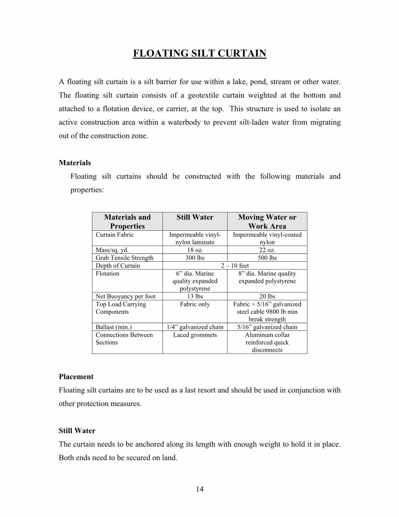
FLOATING SILT CURTAIN
A floating silt curtain is a silt barrier for use within a lake, pond, stream or other water.
The floating silt curtain consists of a geotextile curtain weighted at the bottom and
attached to a flotation device, or carrier, at the top. This structure is used to isolate an
active construction area within a waterbody to prevent silt-laden water from migrating
out of the construction zone.
Materials
Floating silt curtains should be constructed with the following materials and
properties:
Materials and Properties
Still Water Moving Water or Work Area
Curtain Fabric Impermeable vinyl-nylon laminate
Impermeable vinyl-coated nylon
Mass/sq. yd. 18 oz. 22 oz. Grab Tensile Strength 300 lbs 500 lbs Depth of Curtain 2 – 10 feet Flotation 6” dia. Marine
quality expanded polystyrene
8” dia. Marine quality expanded polystyrene
Net Buoyancy per foot 13 lbs 20 lbs Top Load Carrying Components
Fabric only Fabric + 5/16” galvanized steel cable 9800 lb min
break strength Ballast (min.) 1/4” galvanized chain 5/16” galvanized chain Connections Between Sections
Laced grommets Aluminum collar reinforced quick
disconnects
Placement
Floating silt curtains are to be used as a last resort and should be used in conjunction with
other protection measures.
Still Water
The curtain needs to be anchored along its length with enough weight to hold it in place.
Both ends need to be secured on land.
14

Still Water Floating Curtain Plan View
o If a silt curtain is necessary in flowing water to capture up-stream disturbance,
place curtains diagonally alternating from banks.
o Do not extend the silt curtain out more than 1/3 of the stream width.
o Do not place the silt curtain across a flowing channel in its entirety. The channel
bottom will suffer from major scouring
Floating Silt Curtain Diagonal Layout
Moving Water
A buoy accompanies each anchor. The curtain should be anchored with a minimum 300
lbs out in the waterway, and placed a minimum 25 feet from the work area. This
configuration should be used when the work area encroaches more than 1/4 but less than
1/3 of the stream width and the maximum water velocity is 5 ft/sec.
15

Moving Water Floating Curtain Plan View
Work Area
When the work area extends less than 1/4 of the stream width and has a velocity of 5
ft/sec or less, the area is enclosed with a silt curtain. The curtain should extend outward
from shore at a 45 degree angle and should not extend more than 1/3 of the stream width.
Anchor with a minimum 40 lbs at a maximum 100 ft interval.
16
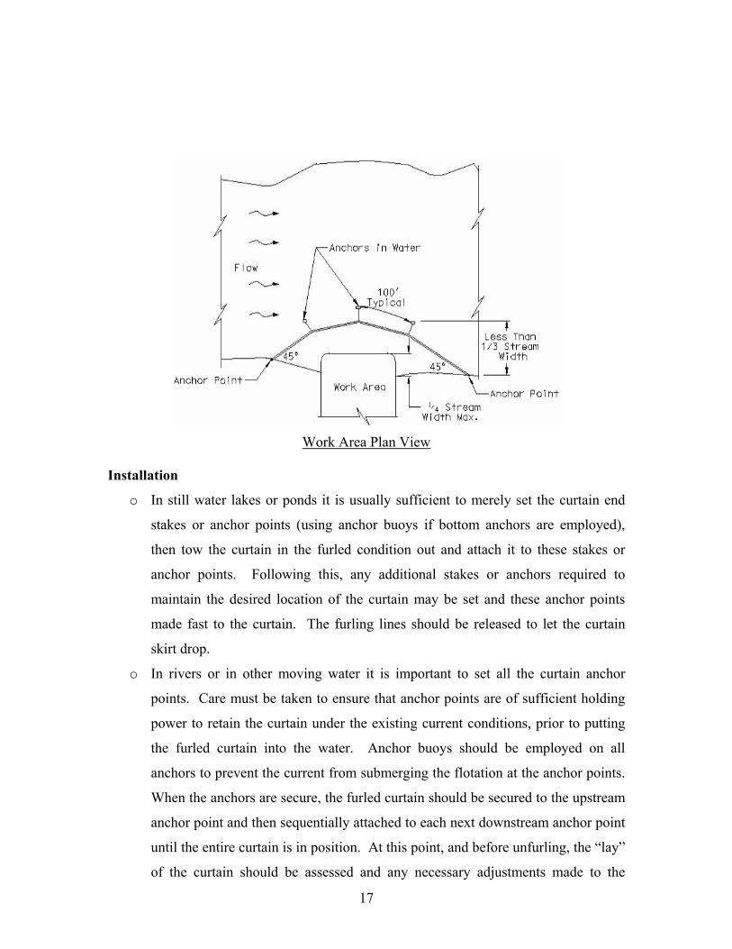
Work Area Plan View
Installation
o In still water lakes or ponds it is usually sufficient to merely set the curtain end
stakes or anchor points (using anchor buoys if bottom anchors are employed),
then tow the curtain in the furled condition out and attach it to these stakes or
anchor points. Following this, any additional stakes or anchors required to
maintain the desired location of the curtain may be set and these anchor points
made fast to the curtain. The furling lines should be released to let the curtain
skirt drop.
o In rivers or in other moving water it is important to set all the curtain anchor
points. Care must be taken to ensure that anchor points are of sufficient holding
power to retain the curtain under the existing current conditions, prior to putting
the furled curtain into the water. Anchor buoys should be employed on all
anchors to prevent the current from submerging the flotation at the anchor points.
When the anchors are secure, the furled curtain should be secured to the upstream
anchor point and then sequentially attached to each next downstream anchor point
until the entire curtain is in position. At this point, and before unfurling, the “lay”
of the curtain should be assessed and any necessary adjustments made to the
17

anchors. Finally, when the location is ascertained to be as desired, the furling
lines should be released to allow the skirt to drop.
o Always attach anchor lines to the flotation device, not to the bottom of the curtain.
Floating Silt Curtain Detail
Removal
Silt curtain should be cleaned out before removal. Removal can take place after work
areas are removed and/or final grading on above slopes is completed. Silt fence or
similar sediment control device should be installed at the toe of the slope before the silt
curtain is removed and remain in place until the vegetation is established. Silt fence is
not necessary if the slope is covered with riprap.
18
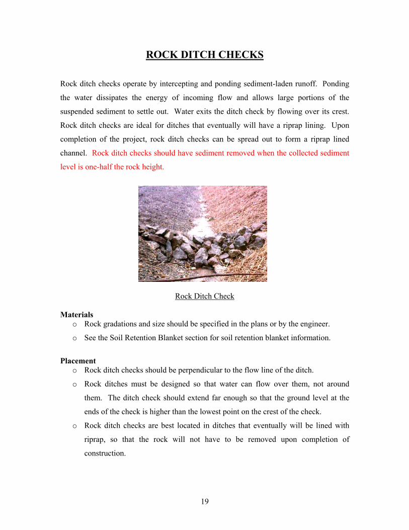
ROCK DITCH CHECKS
Rock ditch checks operate by intercepting and ponding sediment-laden runoff. Ponding
the water dissipates the energy of incoming flow and allows large portions of the
suspended sediment to settle out. Water exits the ditch check by flowing over its crest.
Rock ditch checks are ideal for ditches that eventually will have a riprap lining. Upon
completion of the project, rock ditch checks can be spread out to form a riprap lined
channel. Rock ditch checks should have sediment removed when the collected sediment
level is one-half the rock height.
Rock Ditch Check
Materials o Rock gradations and size should be specified in the plans or by the engineer.
o See the Soil Retention Blanket section for soil retention blanket information.
Placement o Rock ditch checks should be perpendicular to the flow line of the ditch.
o Rock ditches must be designed so that water can flow over them, not around
them. The ditch check should extend far enough so that the ground level at the
ends of the check is higher than the lowest point on the crest of the check.
o Rock ditch checks are best located in ditches that eventually will be lined with
riprap, so that the rock will not have to be removed upon completion of
construction.
19

Rock Ditch Check Spacing Ditch Grade
(Percent) Check Spacing
(Feet) 4.0 75 5.0 60 6.0 50 7.0 45 8.0 35 9.0 33 10.0 30
Installation o The ditch check should be 18 to 24 inches high and have side slopes no steeper
than 1:1. The rock ditch check must be constructed so that water can flow over
the top, not around the ends.
o 8-inch landscape staples should be used as necessary to anchor the erosion control
blanket.
Detail of Rock Check Installation
Profile of Rock Check
20

Rock Ditch Check
Maintenance
Problem Corrective Maintenance
Scour beneath rock
Add rock or fabric Add ditch checks to slow water above the
rock
Dislodged rock Add rock or fabric Regrade
Sediment level at one half the rock
height Clean out
Removal
Rock ditch checks should be removed or placed where specified in the plans when the
site has been stabilized. All sediment accumulated at the barrier should be removed and
all excavation should be backfilled and properly compacted. The site should be graded to
blend with the terrain. The disturbed area must be seeded following removal of ECM’s.
21

GEOTEXTILE TRIANGULAR DIKE
Geotextile Triangular Dikes (GTD) should be used as a continuous line barrier at the toe
of slopes to contain sediment or as a ditch barrier placed perpendicular to the flow of
water in a defined drainage ditch to minimize erosion and contain sediment. Geotextile
Triangular Dikes should have sediment removed when the collected sediment level is
one-half the dike height.
Geotextile Triangular Dike
Materials
o Woven geotextile fabric
o Triangular shaped inner material should be composed of urethane foam
o The metal landscape staples used should be at least 6 to 8 inches long
Geotextile Triangular Dike Profile
22

Placement
o The dike should extend far enough so that the bottoms of the ends are higher than
the top of the lowest center. This prevents water from flowing around the dike.
o Dikes should not be placed in ditches where high flows are expected. Rock
checks or an appropriate alternative should be used instead.
o Dikes should be placed in ditches with a slope of 4 percent or less. For slopes
steeper than 4 percent, rock checks or an appropriate alternative should be used.
Geotextile Triangular Dike Spacing Ditch Grade
(Percent) Check Spacing
(Feet) 1.0 200 2.0 100 3.0 65 4.0 50
>4.0 Do not use GTD
Installation
o Excavate a trench along the entire length of the dike that is at least 4 inches deep
by 4 inches wide perpendicular to the flow line. Place the soil on the upstream
side of the trench for later use.
o Each dike has two aprons: one upstream and one downstream. The upstream
apron is the shorter of the two.
o Conform the flexible dike to the geometry of the ditch so that no space exists
between the dike and the ditch bottom. Place the first 6 inches of the upstream
apron into the trench and anchor it with one row of 6 inch to 8-inch landscape
staples at 18-inch centers.
o Place 6 inch to 8-inch landscape staples on 18-inch centers between the trench
and seam, along the seam on the upstream side, where the downstream apron
meets the dike, and on the edge of the downstream apron.
o Each dike has an open sleeve at either end. Connect adjoining dikes with these
sleeves and then repeat the anchoring procedure.
o Once all the dikes have been joined and anchored, fill in the upstream trench with
soil and compact it.
23

o Do not place dikes directly in front of a culvert outlet because they will not stand
up to the concentrated flow.
Geotextile Triangular Dike Detail
Maintenance
Problem Corrective Maintenance
Runoff escaping around the dike Lengthen the dike
Water flowing under the dike
Reanchor, add more as needed
Sediment level at one half the dike
height Clean out
Removal
The Geotextile Triangular Dikes should be removed when the site has been stabilized.
All sediment accumulated behind the barrier should be removed and all the excavation
should be backfilled and properly compacted. Smooth the site to blend with the terrain.
The disturbed area must be seeded following removal of ECM’s.
Geotextile Triangular Dike with Rock Backing
24

INLET PROTECTION
The purpose of inlet protection is to prevent sediment from entering storm drainage
systems, prior to temporary or permanent stabilization of the disturbed area. This
practice contains several types of inlet filters and traps that have different applications
dependent upon site conditions and type of inlet. Other innovative techniques for
accomplishing the same purpose are encouraged and should be submitted for approval of
the on site engineer. Sediment that is collected around the inlet should be removed when
the sediment levels reach half the height of the ECM.
Design Considerations
o The drainage area should be no greater than one acre. Runoff from larger
disturbed areas should be routed to a Temporary Sediment Trap or a Temporary
Sediment Basin.
o The inlet protection device should be constructed in a manner that will facilitate
cleanout and disposal of trapped sediment and minimize interference with
construction activities.
o The inlet protection devices should be constructed in such a manner that storm
water will not cause excessive ponding.
Silt Fence Inlet Structure
Silt fence inlet protection structures intercept, pond and filter sediment-laden runoff.
Ponding the water reduces the velocity of the incoming flow and allows most of the
suspended sediment to settle. As the ponded water percolates through the silt fence
fabric, much of the remaining suspended sediment is filtered out.
Materials o The material used to frame the tops of the posts should be 2 inch x 4 inch
(nominal). Use nails or screws for fastening.
o Woven wire
25
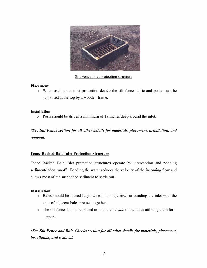
Silt Fence inlet protection structure
Placement o When used as an inlet protection device the silt fence fabric and posts must be
supported at the top by a wooden frame.
Installation o Posts should be driven a minimum of 18 inches deep around the inlet.
*See Silt Fence section for all other details for materials, placement, installation, and
removal.
Fence Backed Bale Inlet Protection Structure
Fence Backed Bale inlet protection structures operate by intercepting and ponding
sediment-laden runoff. Ponding the water reduces the velocity of the incoming flow and
allows most of the suspended sediment to settle out.
Installation o Bales should be placed lengthwise in a single row surrounding the inlet with the
ends of adjacent bales pressed together.
o The silt fence should be placed around the outside of the bales utilizing them for
support.
*See Silt Fence and Bale Checks section for all other details for materials, placement,
installation, and removal.
26

Block and Gravel Inlet Barrier
Block and gravel inlet barriers operate by intercepting, ponding, and filtering the
sediment-laden runoff. Ponding the water reduces the velocity of the incoming flow and
allows most of the suspended sediment to settle. As the ponded water percolates through
the Block and Gravel inlet barrier, much of the remaining suspended sediment is filtered
out. Block and Gravel inlet barriers work well in areas of moderate flow and moderate
slopes.
Block and Gravel inlet barrier
Materials
o Concrete masonry blocks – 8 inches x 8 inches x 16 inches
o ½ inch opening wire screen
o 1 ½ inch diameter maximum size gravel
Placement
o When the Block and Gravel inlet barrier is placed in a shallow median ditch,
make sure the top of the barrier is not higher than the road. Otherwise, water may
spread onto the roadway causing a hazardous condition.
27

Installation
o Place concrete blocks around the inlet structure to a height of 2 feet.
o Place the wire screen against the blocks. The wire screen may have to be secured
to the blocks to allow placement of the gravel.
o Place gravel against the wire to the top of the barrier.
Block and Gravel Inlet Barrier Detail
Removal
The barrier should be removed and the area stabilized when the remaining drainage area
has been properly stabilized. If possible, leave the gravel around the inlet to dissipate
energy from the water. The gravel should be leveled out, so that the water does not pond
once the site is stabilized.
Block and Gravel Curb Inlet Barrier
The block and gravel curb inlet barrier operates on the same concepts as the block and
gravel inlet barrier.
Materials
o Concrete masonry blocks – 8 inches x 8 inches x 16 inches
o ½ inch opening wire screen
o 1 ½ inch maximum size gravel
o 2 inch x 4 inch (nominal) wood stud
28

Placement
o This method of inlet protection is applicable at curb inlets where an overflow
capability is necessary to prevent excessive ponding in front of the structure.
Gravel Curb Inlet Barrier
Installation
o Two concrete blocks should be placed on their sides abutting the curb at either
side of the inlet opening.
o A 2 inch by 4-inch (nominal) stud should be cut and placed through the outer
holes of each spacer block to help keep the front blocks in place.
o Concrete block should be placed on their sides across the front of the inlet and
abutting the spacer blocks as illustrated.
o Wire mesh should be placed over the outside vertical face (webbing) of the
concrete block to prevent stone from being washed through the holes in the
blocks.
o Place gravel against the wire to the top of the barrier.
29

Block and Gravel Curb Inlet Barrier Details
Maintenance
Problem Corrective Maintenance
Flooding around or below inlet.
Stakes and fabric leaning/falling in
toward grate.
Check grade
Regrade or redesign Check for blockage in culvert or catch basin
Undercutting of bales or silt fence, bale displacement,
torn fabric, etc.
Replace, rearrange and/or regrade
Sediment level at one half the ECM Clean out
Removal
The curb barrier should be removed when the remaining drainage area has been properly
stabilized.
30

SEDIMENT TRAP
The purpose of this practice is to detain sediment-laden runoff from small-disturbed areas
for a sufficient period to allow the majority of sediment and other water-based debris to
settle out. Sediment traps should have sediment removed when the sediment level is
more than ½ the depth or sediment is near the outlet elevation.
Sediment Trap
Design Considerations
o The drainage area should be no greater than 5 acres.
o Runoff from larger disturbed areas should be routed to a Sediment Basin.
Materials
o Riprap
o Geotextile fabric should be placed underneath the riprap outlet
Placement
o Typical locations include ditch bottoms, and the downgrade end of a cut section,
and areas where it becomes necessary to capture larger amounts of sediment
where a silt fence continues to fail.
31

Installation
o Excavate the sediment trap to the appropriate dimensions and remove the soil and
place it in an area and in such a manner that it will not erode. The trap should be
at least twice as long as it is wide.
o Place geotextile fabric where the riprap is to be placed.
o Place riprap on the downstream side of the trap extending 6 feet downstream.
The riprap should be placed the width of the trench plus ½ foot on each side.
Plan View of Sediment Trap
Profile of Sediment Trap
Maintenance
Problem Corrective Maintenance
Obstructed outlet Clean and Regrade Damaged
embankments Regrade, Redesign
Spillway erosion Regrade, Add rock Excessive discharge
to and from trap Look for breaks in trap
Sediment storage zone fills to quickly
Add basins or traps Add ditch checks
Sediment level more than ½ the
depth or sediment near outlet elevation
Clean out
32

Removal
Temporary sediment traps should be filled in and graded over at the time of final shaping.
The rock should be removed or be buried in the hole first. The disturbed area must be
seeded following removal of ECM’s.
33

SURFACE ROUGHENING
Surface Roughening is a practice that abrades the soil surface with horizontal ridges and
depressions across the slope, decreasing erosion by reducing runoff velocities. In
addition, this practice also increases infiltration and fosters the establishment of
vegetation.
Tracking
Tracking is a method that utilizes the depressions formed by the tracks from bulldozers
and other construction vehicles. The vehicle is driven parallel to the slope leaving
horizontal depressions. These depressions interrupt the runoff’s flow, reducing its
velocity and erosive capacity.
o Tracking should be performed on all slopes of 3:1 or steeper that can be
mechanically climbed.
o The tracking vehicle is to be operated up and down the slope and leaves behind
horizontal depressions in the soil.
34

MULCHING Specification 708.02
Mulching is done primarily with Hydro-mulch or Straw Mulch. Mulching involves the
application of straw or other organic materials to form a temporary, protective soil cover.
Mulch protects the soil surface from the forces of raindrop impact and overland flow.
Organic mulches foster the growth of vegetation, reduce evaporation, insulates the soil,
and suppresses weed growth.
Hay or Straw Mulching
Machine Blown Mulch
Materials
o Mulch material should consist of native hay or the straw from oats or barley, and
should be seed free to prevent introduction of weeds as defined by the rules and
regulations of the North Dakota Department of Agriculture.
o At least 50% of the mulch by weight should be 10 inches or more in length.
Placement
o The mulch should be machine blown and should be uniformly distributed over the
seeded areas. The machine should be of a design that minimizes cutting or
breaking of the mulching material.
o Mulching operations should not be performed during periods of excessively high
winds, which would preclude the proper placing of the mulch.
o Mulch containing excessive moisture which prevents uniform feeding through the
machine should not be used.
o Bales should be broken up and loosened as they are fed into the blower to avoid
placement of matted or unbroken lumps.
35

Installation
o The mulch should be placed within 24 hours after the seeding has been
completed.
o The mulch should be placed uniformly over the seeded areas at the rate of 2 tons
per acre.
o Approximately 10% of the soil surface should be visible through the mulch
blanket before the mulch tiller (punching) operation.
Maintenance
Problem Corrective Maintenance
Rills or gullies forming
Regrade and reseed, Add additional
controls Bare soil patches Remulch and/or reseed
Sediment at the toe of the slope
Regrade, Add silt fence or filter dike if
next to a body of water
Hydro-mulching
Hydro-mulching
Materials
Hydro-mulching is used when Class III seeding is specified. It contains a wood cellulose
fiber that has not been treated with any germination or growth inhibitive substance but
will be treated with a tackifier to enhance seed and mulch placement and adherence to the 36

soil. The mulch should be free of contamination from noxious weed seed and seed from
competitive plants.
Placement
The mulch should be uniformly applied at a rate of one ton per acre and should cover a
minimum of 95% of the seedbed area. After application, the mulch should permit
percolation of water to the underlying soil.
Removal
Mulching does not need to be removed.
37

SOIL RETENTION BLANKET Specification 708.03
Soil Retention Blankets are biodegradable materials that can be used to protect disturbed
slopes and channel areas from wind and water erosion. The blanket materials are natural
materials such as straw, wood excelsior, coconut, or are geotextile synthetic woven
materials.
Straw-Coconut Fiber Mat
Materials
Wood Excelsior Fiber Mat
o The wood excelsior fiber mat should consist of a machine produced mat of cured
wood excelsior in which 80% of the fibers are 6 inches or longer.
o The fiber should have a consistent thickness of fiber evenly distributed over the
entire area.
o The top of each mat should be covered with a photo-degradable extruded plastic
mesh with maximum openings of 1 inch by 3 inches.
o The wood excelsior fiber mat should be treated to be smolder resistant without
using chemical additives.
Wood Excelsior Fiber Mat Physical Properties Width Minimum 36 inches
Roll Length Minimum 100 feet Minimum 0.7 lbs/yd2Weight
38

Straw and Fiber Mats
A. Straw Mat
o The straw mat shall be machine produced of clean straw from agricultural crops
and be sewn together with biodegradable cotton or nylon thread.
o The top side should be covered with a biodegradable plastic mesh or netting with
maximum openings of 5/8 by 5/8 inches.
Straw Mat Physical Properties Width Minimum 48 inches
Roll Length Minimum 80 feet Minimum 0.5 lbs/yd2Weight
B. Straw Mat with Mesh or Netting on Top and Bottom
o Material should coincide with the Straw Mat except that it should be furnished
with mesh or netting on the top and bottom of the mat.
C. Straw-Coconut Fiber Mat
o Material should coincide with the Straw Mat except that the mat should consist of
70% straw and 30% coconut fibers.
D. Straw-Coconut Fiber Mat with Mesh or Netting on Top and Bottom
o Material should coincide with the Straw Mat with Mesh or Netting on Top and
Bottom except that the mat shall consist of 70% straw and 30% coconut fibers.
E. Coconut Fiber Mat
o Material should coincide with the Straw Mat with Mesh or Netting on Top and
Bottom except that the mat should be machine produced or 100% coconut fiber
and shall be sewn together with biodegradable nylon (polyester) thread.
o Both the top and bottom should be covered with a biodegradable plastic mesh of
netting.
o One side should be heavy duty mesh with a minimum weight of 2.5 pounds per
1,000 ft2.
o Maximum size mesh openings should be 5/8 by 5/8 inches.
39

Placement
Soil Stabilization Mats may be suitable for:
o Stabilization of steep to moderate slopes
o New landscaped areas
o Drainage swales and ditches that are to be planted or seeded
Retention Blanket in Ditch
Installation
o The area to be covered should be properly prepared and seeded before the blanket
is applied. All rocks or clods of 1 ½ inches in diameter or greater, and all sticks
and other foreign material should be removed.
o If netting is specified for one side only, the blanket should be placed with the
netting on top and the fibers in contact with the soil.
o In ditches, blankets should be unrolled in the direction of water flow, and stapled
every 5 feet at joints and edges or as specified in the plans. When multiple
blankets are used, the upstream blankets should overlap the downstream blankets.
o On slopes, blankets may be unrolled either horizontally or vertically to the slope.
Ends and sides shall be stapled. When multiple blankets are utilized, the upslope
blanket should overlap the down slope blanket.
40
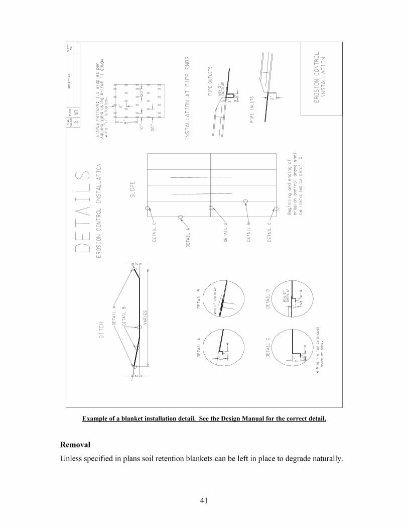
Example of a blanket installation detail. See the Design Manual for the correct detail.
Removal
Unless specified in plans soil retention blankets can be left in place to degrade naturally.
41

TEMPORARY SLOPE DRAIN
A slope drain is a flexible tubing or conduit extending from the top to the bottom of a cut
or fill slope. Its purpose is to temporarily conduct runoff safely down the disturbed face
of an embankment without causing erosion.
Slope Drains
Materials
o Heavy duty flexible tubing or conduit designed for this purpose
o The diameter of the tubing or conduit should be uniform over its entire length
o Hold down stakes
o Optional riprap for outlet protection
Placement
o On cut or fill slopes before permanent stormwater drainage structures are installed
and before permanent erosion control vegetation is established.
o Place slope drains on undisturbed soil or well-compacted fill.
Installation
o The soil around and under the entrance section should be hand tamped to the top
of the dike to prevent piping failure around the inlet.
o The inlet section may need to be modified for each situation
o The slope drain should be securely staked to the slope at the grommets provided.
42

o The slope drain sections should be securely fastened together and have watertight
fittings.
o If the drain is conveying sediment-laden runoff, direct all flows into a sediment
trap or other adequate sediment control device.
o Installation of temporary slope drains should be completed and their outlets
protected before runoff is diverted to them.
Profile of Slope Drain
Plan View of Slope Drain
43

Slope Drain used with a combination or other measures
Maintenance
Problem Corrective Maintenance
Blocked inlet or outlet
Unblock and regrade
Runoff bypassing inlet
Regrade
Erosion at outlet Add rock
Removal
The Temporary slope drain can be removed once the reason for the drain is no longer
necessary, i.e. permanent vegetation has been established or a permanent structure has
been placed to address the water issue.
44
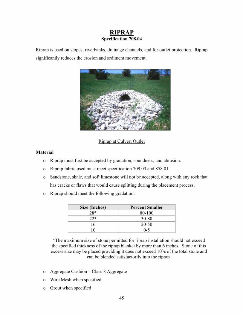
RIPRAP Specification 708.04
Riprap is used on slopes, riverbanks, drainage channels, and for outlet protection. Riprap
significantly reduces the erosion and sediment movement.
Riprap at Culvert Outlet
Material
o Riprap must first be accepted by gradation, soundness, and abrasion.
o Riprap fabric used must meet specification 709.03 and 858.01.
o Sandstone, shale, and soft limestone will not be accepted, along with any rock that
has cracks or flaws that would cause splitting during the placement process.
o Riprap should meet the following gradation:
Size (Inches) Percent Smaller 28* 80-100 22* 30-80 16 20-50 10 0-5
*The maximum size of stone permitted for riprap installation should not exceed the specified thickness of the riprap blanket by more than 6 inches. Stone of this excess size may be placed providing it does not exceed 10% of the total stone and
can be blended satisfactorily into the riprap.
o Aggregate Cushion – Class 8 Aggregate
o Wire Mesh when specified
o Grout when specified
45

Riprap may be suitable:
o Along a stream or within drainage channels, as a stable lining resistant to erosion.
o On lakefronts and riverfronts, or other areas subject to wave action.
o Around culvert outlets and inlets to prevent scour and undercutting.
o In channels where infiltration is desirable, but velocities are too excessive for
vegetative or geotextile lining.
o On slopes and areas where conditions may not allow vegetation to grow.
Riprap
Installation
o Slopes should be excavated, shaped, and completed to the required cross section
and elevation.
o Install an aggregate cushion to the specified depth and shape.
o When loose riprap is laid on a slope, placement must begin at the toe of the slope
and work up the hill. At the toe, a trench should be dug to the specified size. If
no size is specified, the trench will be at least one foot deep and the width of the
area. The larger rocks are to be placed in the trench first.
o The riprap should be compacted throughout the process and the finished surface
should have an even, tight surface. Any gaps will be filled with smaller rock.
46

o Rocks may be placed by mechanical means or by hand but should be distributed
evenly.
o The area will not deviate from plan slope and grade by more than 6”.
o When wire mesh riprap is specified, a wire mesh will be placed above, below, and
around the ends and sides of the riprap. The ends of strips will be tied every 18”
at all abutting sections. End splices should be staggered at least 10’. No mesh
under 10’ of length will be used. The lower layer of mesh will be tied to the
upper layer at a minimum of 2’ on center each way.
Removal
Temporary riprap should be removed and disposed of in accordance with the plans or
direction of the engineer.
47

SEEDING and SODDING Specification 708.02
SEEDING
Tractor mounted seed drill
Material
o The species and variety of seed used should be specified in the plans and should
meet or exceed Pure Live Seed requirements.
o Seed and seeding mixtures should be free of all prohibited noxious weed seed and
should not contain more than ½ of 1% by weight of restricted noxious weed seeds
as classified by the North Dakota State Seed Department.
o Seed will be accepted by certification after it has been tested by an approved
laboratory within nine months of planting. Seed that has not been planted within
nine months of testing will need to be retested.
o Seed that has become wet, moldy or damaged before it is planted will not be
accepted.
o Fertilizer should be placed according to the class of seed as specified in the
specifications.
o When hydro-mulch is used, the fertilizer should be in the slurry mixture.
Placement
o Areas to be seeded should be done as specified in the plans.
48

Installation
o Areas to be seeded should be cleared of all material that is detrimental to seedbed
preparation.
o The cleared areas should be shaped to the plan cross sections, or to the cross
section that best fits existing conditions.
o Grass seeds of the required mixture and quality shall be sown by a mechanical
seeder or other method, which will sow a uniform quantity as required over the
whole area to be seeded.
o No seed should be sown when the wind velocity exceeds 15 miles per hour.
o No seed should be sown in standing water or frozen ground.
o All slopes should be worked on the contour, or as directed by the Engineer.
o Seeded areas should be watered and mulched immediately following placement
when specified by the project designer or site conditions dictate.
Maintenance
Problem Corrective Maintenance
Rills or gullies forming
Regrade and reseed, Add additional
controls Bare soil patches Remulch and/or reseed
Sediment at the toe of the slope
Regrade, Add silt fence or filter dike if
next to a body of water
49

SODDING
Sod Installation
Material
o Sod shall consist of dense well-rooted growth of permanent and desirable grass,
with uniform thickness that is adapted to the general location of which it is
placed.
o Sodding must be accompanied by a certification of compliance (from an approved
laboratory) stating that the soil upon which the furnished sod was grown does not
contain more than 20% organic matter. The percentage of organic matter shall be
determined according to the latest version of AASHTO test method T-267. If the
sod comes from multiple locations, each location will require certification. The
certifications for the fields are good for 5 years.
o All sod shall be free of weeds and undesirable grasses and shall be cut when the
grass is less than two inches tall.
o Peat sod will not be allowed.
Placement
o Prior to placement, the area to be sodded shall be shaped to the required cross
section and contoured in accordance with the plans.
o Stones larger than two inches diameter and other debris, which will interfere with
proper placement or growth of the sod, shall be removed.
50

o Immediately prior to placing the sod, the soil shall be loosened and lumps, weeds
and other undesirable materials shall be removed.
o Sod on slopes shall be laid in horizontal strips beginning at the bottom of the
slope working upwards.
o In ditches, the long length of the strip shall be placed perpendicular to the flow.
Installation
o Each section of sod shall join the adjacent section without overlapping but shall
abut snugly against the section previously laid. End joints shall be staggered and
open joints or gaps shall be filled with sod cut to the proper size and shape.
o On slopes of 4:1 or steeper, the sod shall be anchored with stakes of at least 6
inches in length spaced 18 inches to 36 inches apart along the longitudinal axis of
the sod strip.
o Fertilizer should be placed as specified in the plans.
o Maintenance and watering shall be done for 4 weeks after the sod is laid. Any sod
that dies, washes out, is damaged, or contains excessive organic material during
this maintenance period will be replaced at the contractor’s cost.
51

SANDBAGS
Sandbags can be used to dike off an area, divert water, control a ditch grade, and be used as inlet protection.
Sand Bag Barrier
Materials
o Sandbags should be woven polypropylene, polyethylene or polyamide fabric.
o All sandbag fill material should be non-cohesive permeable material free from
clay and deleterious material.
Placement
Sandbag barriers may be suitable:
o As sediment traps at culvert/pipe outlets
o Below the toe of slopes and erodible slopes
o Down slope of exposed soil areas
o Around storm sewer inlets.
Installation
o Sandbags need to be stacked tightly against one another in a pyramidal-type
fashion.
52

o Generally a bag or two is left out of the top row to provide a spillway.
Pyramidal Stacking Pattern (Number of Rows Vary)
Removal
Remove sandbags when no longer needed. Remove sediment accumulation, clean,
regrade if necessary, and stabilize the area. The disturbed area must be seeded following
removal of ECM’s.
53

OTHER MEASURES
FLOATING SILT CURTAIN
A floating silt curtain is a silt barrier for use within a lake, pond, stream or other water.
The floating silt curtain consists of a geotextile curtain weighted at the bottom and
attached to a flotation device, or carrier, at the top. This structure is used to isolate an
active construction area within a water body to prevent silt-laden water from migrating
out of the construction zone.
STABILIZED CONSTRUCTION ACCESS
A stabilized construction access is a defined point of entrance/exit to a construction site
that is stabilized to reduce the tracking of mud and dirt onto public roads by construction
vehicles. Stabilized construction access is typically 50 to 100 feet in length and is
comprised of large aggregate.
STRAW WATTLES
Straw wattles are permeable barriers used to detain runoff long enough to reduce flow
velocity and allow sediment to settle out.
54

Inspection and Maintenance Inspection
Inspect ECM controls at least once every 7 days and within 24 hours after any storm
event of ½ inch or more. The following things should be evaluated:
o Ascertain whether controls are adequate and properly implemented according to
the schedule of operations or whether additional control measures are required.
o Inspect disturbed areas and storage areas for potential or evidence of pollutants
entering the drainage system.
o Inspect discharge locations to ascertain whether control measures are effective in
preventing significant impacts to receiving waters.
o Inspect entrances and exits of site for evidence of off-site tracking.
Maintenance
All control practices will be maintained and repaired as needed to assure continued
performance of their intended function. Each ECM previously discussed has
maintenance issues, additional maintenance information is discussed below.
ECM Problem Corrective Measure Outlet Protection Erosion below
outlet Add Rock, Add ditch
checks to slow the water
Sediment leaving project
Add sediment basins, ditch checks, silt fence
etc. Dislodged Rock Add or rearrange rock
General Ditch Erosion and
Sediment Problems
Loose soil Regrade, Recompact Erosion of Ditch Regrade, Add
additional controls Gully on slope
above ditch Regrade, Add Slope Drains, Add Rock
Sediment or debris in ditch
Clean Out, Regrade and add ditch checks
and/or sediment basins Erosion of unlined
ditch surface Place ditch checks or to slow the water or sediment blankets
Erosion of ditch blankets
Straighten, Regrade, Reline, and Repin
more securely.
55

Example of Site Monitoring form
56

NPDES PERMITS
The National Pollution Discharge Elimination System (NPDES) is a program aimed to
reduce and eventually eliminate pollution from point and non-point sources. In North
Dakota, the NPDES is administered and enforced by the North Dakota Department of
Health (NDDOH), where it is referred to as the North Dakota Pollution Discharge
Elimination System (NDPDES). The forms required for individual permits can be found
on the NDDOH’s website located at
http://www.health.state.nd.us/wq/Storm/StormWaterHome.htm.
An operator (a person in charge of day to day supervision and in control of activities
occurring at the construction sites) or owner (NDDOT) of construction activity needs a
permit:
o If land disturbance (clearing, grading, or excavating) is greater than or equal to
one acre.
o If land disturbance is less than one acre and the site is part of a larger common
plan of development or sale with the total land area disturbed in the development
being equal to or greater than one acre. An example of this is a highway
construction project that includes twelve half-acre sections that are not connected
to each other but the combined total area of the twelve sites equals six acres.
o If there is potential for contribution to a violation of a water quality standard or
potential for significant contribution of pollutants to waters of the state.
Permit Contents:
1. Storm Water Pollution Prevention (SWPP) Plan
The core of the permit process is the Storm Water Pollution Prevention Plan. This packet
of forms is used to describe the scope of the project, erosion and sediment control
measures, and other measures taken to prevent pollutants from leaving the site with storm
water.
57

Elements of a SWPP Plan:
1. Project Description (SF 19388)
2. Site Map Development
3. Vegetative/Structural Practices (SF 19389)
4. Other Erosion Control Measures (SF 19390 and SF 19390-2)
5. Significant Materials (SF 19387)
6. Signatory Certification (SF 19137)
2. Notice of Intent (NOI):
Small Construction Activity - Land disturbance of equal to or greater than one acre and
less than five acres and when the disturbance of less than one acre of total land area that
is part of a larger common plan of development or sale. Erosion control measures must
be implemented in order to prevent erosion and sediment runoff.
An operator of a small construction activity must submit one single NOI form to the
NDDOH to obtain coverage of the storm water discharges from all of their small
construction sites. The NOI for small construction activity should contain, at a minimum,
the following information:
o Name and mailing address of the owner or operator
o Contact name and phone number
o A brief description of the construction activity type
o The signature of the applicant(s)
The NOI for small construction should be submitted to the NDDOH prior to the start of
construction. A SWPP does not need to be submitted for small construction activity
unless requested in writing by the NDDOH.
Large Construction Activity – Land disturbance greater than or equal to five acres. Large
construction activity also includes the disturbance of less than one acre of total land area
that is part of a larger common plan of development or sale, if the larger common plan
will ultimately disturb equal to or greater than five acres. An example of this is a
58

highway construction project that includes twelve half-acre sections that are not
connected to each other but the combined total area of the twelve sites equals six acres.
The operator of a large construction activity should submit a NOI and SWPP Plan to
obtain coverage for storm water discharges for each construction project. The NOI for
large construction activity should contain, at a minimum, the following information:
o Name and mailing address of the owner or operator
o Contact name and phone number
o The type of owner or operator of the construction site (federal, state, private, or
other entity)
o Name of construction project
o A brief description of the construction activity
o List of contractors/subcontractors working at the site (if known)
o Construction project’s Standard Industrial Code (SIC) code
o The anticipated starting date and the anticipated date of the completion for the
project
o The estimated area of total disturbance in acres
o County and location of the construction site, including latitude and longitude or
township, range, section, and ¼ section
o Name of receiving water(s) or the name of the receiving municipal storm sewer
system and receiving water(s)
o The signature of the applicant(s)
The NOI and SWPP Plan for large construction activity should be submitted to the
NDDOH 30 days prior to the start of construction.
59

Example of the NOI Form
60

3. Permit Certification:
Automatic Coverage – If the applicant does not receive a request for additional
information or a notification of denial from the NDDOH within 10 days of receipt of the
application by NDDOH, authorization to discharge in accordance with the conditions of
this permit shall be deemed granted.
Request for Additional Information – The NDDOH shall have the right to request
additional data and/or deny the authorization for any particular discharge.
Individual or Alternative General Permits – Refer to the NDDOH for individual or
alternative general permits.
Local Authority – This permit does not preempt or supersede the authority of local
agencies to prohibit, restrict, or control discharges or storm water to storm sewer systems
or other water courses within their jurisdiction.
4. Continuation of Coverage
Facilities covered under this permit can continue coverage under the renewed permit,
provided a satisfactory request is made. Any request to retain coverage under a renewal
of this permit shall be made in writing to the NDDOH at least 15 days prior to the
expiration date of this permit. If requested by the NDDOH, a new NOI should be
submitted.
5. Transfer of Ownership or Control
o Coverage under this permit may be transferred to a new permittee if the existing
and new permittees notify the NDDOH in writing, at least 48 hours before the
transfer of ownership or control; and the notice includes a written agreement
between the existing and new permittees containing a specific date of transfer of
permit responsibility, coverage and liability between them. If requested by the
NDDOH, a Notice of Termination should be submitted by the existing permittee
and a NOI submitted by the new permittee. Contractors will be responsible for
61

transferring ownership to the NDDOT following the final project inspection and
written acceptance. All erosion control measures must be installed properly and
cleared of all sedimentation. Following final inspection and written acceptance,
all maintenance operations will be performed by the NDDOT Districts and the
SWPP Plan measures will be followed.
o The new owner or operator must comply with all regulations in this permit and
with all provisions of the existing SWPP Plan until such time as the existing
SWPP Plan is amended or replaced by a new SWPP Plan. If the personnel
responsible for implementing the SWPP Plan change, these changes must be
amended to the SWPP Plan within 30 days of transfer of ownership or control.
6. Notice of Termination (NOT)
Final Stabilization is reached when all construction activities that are authorized by
this permit have been completed, and uniform vegetative cover has been established
with a density of at least 70 percent of pre-disturbed levels, or equivalent permanent,
physical erosion reduction methods have been employed. The NDDOH has a form
available on their website that must be completed for this step.
Operators of small construction activity are not required to submit a notice of
termination for their individual small construction sites, however, final stabilization is
required on all sites. If an operator ceased all of its small construction activity and
has submitted Annual Location Records that certify final stabilization has been
completed on its small construction sites, a notice of termination must be submitted to
end permit coverage for small construction activity. The content of the notice of
termination for small construction activity should contain the following:
o Permit number
o Name and mailing address of the owner or operator
o Contact name and phone number
o Certification that all small construction activity has been stabilized
o Signature of the applicant(s)
62

Example of a NOT form
63

Operators of large construction activity should submit the following when the site has
been stabilized:
o Permit number
o Name of construction site
o Name and mailing address of the owner or operator
o Contact name and phone number
o County and location or the construction site, including latitude and longitude or
township, range, section and ¼ section
o Certification that the site has been stabilized.
o Signature of the applicant(s)
o Once final stabilization has been established, Notice of Terminations will be
prepared by the NDDOT District’s.
NOI’s, SWPP’s and Notice of Termination’s should be submitted by mail, or hand
delivery to:
North Dakota Department of Health Division of Water Quality 1200 Missouri Avenue PO Box 5520 Bismarck, ND 58506-5520
64

Responsibilities within the NDDOT DESIGN
• Coordinate all MS4 activities
• Submit Annual Report to NDDOH
• Design project site plan for Erosion Control Measures (ECM).
• Develop a partnership with the five MS4 permittees to address common issues.
• Develop ECM’s for pre and post construction runoff water quality control.
• Develop and review construction standards for onsite erosion and sediment
control.
• Develop educational material and train personnel on the review of storm water
management plans and inspection procedures.
• Develop penalties for contractors failing to comply with the storm water
management plan.
CONSTRUCTION • Pre-construction staking of ECM’s
• Weekly and Storm Event Runoff (>.50in. /24hrs.) inspection of ECM’s during
construction.
• Enforcement of ECM’s.
• Maintain inspections until final inspection and acceptance.
• Develop penalties for contractors failing to comply with the storm water
management plan.
MAINTENANCE/DISTRICTS
• Responsible for overseeing compliance for insuring MS4 compliance on all
NDDOT projects within MS4 municipalities and properties (State Owned Gravel
Pits and maintenance yards), and submit reports to the Design Division.
• Following final inspection and acceptance the Maintenance/Districts will be
responsible for maintaining and removing all ECM’s until 70% coverage on
disturbed areas is established.
65

• Develop and review construction standards in NDDOT Standard Specifications
for Road and Bridge Construction, for onsite erosion and sediment control.
• Submit Notice of Termination’s to NDDOH and a copy to Design Division.
CONTACTS
Permits
North Dakota Department of Health Division of Water Quality 1200 Missouri Avenue Bismarck, ND 58506-5520
Erosion and Sediment Control
North Dakota Department of Transportation Design Division 608 East Boulevard Avenue Bismarck, ND 58505-0700
66

REFERENCES
American Association of State Highway and Transportation Officials. Guidelines for Erosion and Sediment Control in Highway Construction. 1992.
Minnesota Department of Transportation. Erosion Control Handbook.
Minnesota Department of Transportation. The Inspectors Erosion and Sediment Control Pocketbook Guide. 2003
Montana Department of Transportation. Erosion and Sediment Control Best Management Practices: Reference Manual. 2003
North Dakota Department of Transportation. Standard Specifications for Road and Bridge Construction. Oct. 2002.
North Dakota Department of Health. A Guide to Temporary Erosion-Control Measures for Contractors, Designers, and Inspectors. June 2001.
Ohio Department of Transportation. Handbook for Sediment and Erosion Control. February 2000.
67