eee8076 reconfigurable hardware design (coursework) · use references if you need to quote...
TRANSCRIPT

EEE8076 Reconfigurable
Hardware Design(coursework)
Dr A. BystrovDr. E.G. Chester
Autumn 2010

Module Outline

Teaching Staff
● Dr Alex Bystrov● Dr Graeme Chester
The contact details are in the EECE web page
● Six demonstrators, who are our PhD students.

Aims of the module
● Knowledge, skills and design experience on reconfigurable hardware platforms (FPGA chips) in the context of the respective Degree Programmes.
● Understanding of needs of the modern electronics and comms industry as outlined in the International Technology Roadmap for Semiconductors (current edition).
● Consistency in preparation of the students to the Individual Project

Teaching Methods
● Lectures: 2x2h – this week● Hands-on tutorial: 3h – the next week● Practicals: 9x3h sessions● Private study: 114h !!!
Total: 150 hours per student
Plan your time!!!
Private study: lab, reading, report

Group work
● Groups of 3 students● The list of groups will be distributed
● Define the functions within the group● Organise discussions● Do not copy the reports from each other● Overview and Discussion sections
Assessment● Report: 100%● Each student submits a separate report● Continuous assessment of progress
– by the academic staff
– by the demonstrators
– affects the marks withing a group
● Observe the deadline: 3pm, 14 Jan. 2011– Penalties are severe (see Handbook)

Report
● Individual, one report per student!● 4000 words, up to 50% of tables, diagrams,
code, equations and screen shots● Full listing of code --> Appendix, not
included into the word count● The main text includes only the essential
fragments of code/diagrams. Everything else --> Appendix.

Sections in the report● Title page with your details, st. number, etc.
● Aims and Objectives. Two aims.
● Introduction, including discussion of ITRS on reconfigurable platforms.
● Design specification and the platform
● Implementation
● Experiments and Discussion
● Conclusion
● References

Avoid plagiarism
● Do not cut-and-paste from the other sources
● Discuss rather than paraphrase● Use references● If you need to quote something, use the
quotation marks and the reference.
http://www.ncl.ac.uk/library/resin/writing_up/academic_integrity/plagiarism.php

Handbooks and referenceJ.O. Hamblen, M.D. Furman. Rapid Prototyping of Digital Systems – A Tutorial Approach. Second Edition. 2001, Kluwer (availability: one book per a workstation)
P.J.Ashenden. VHDL Cookbook, http://tams-www.informatik.uni-hamburg.de/vhdl/doc/cookbook/VHDL-Cookbook.pdf, accessed 1/09/2010
Altera Corp. VHDL, http://www.altera.com/support/examples/vhdl/vhdl.html, accessed 1/09/2010
ITRS. http://www.itrs.net/, accessed 1/09/2010
http://www.altera.com/education/univ/unv-index.html
http://www.altera.com/literature/hb/qts/quartusii_handbook.pdf

Reference Cards
Qualis Design Corporation (2007-03-29) (PDF). VHDL quick reference card
http://vega.unitbv.ro/~nicula/asd/resources/vhdl_ref.pdf
Qualis Design Corporation (2007-03-29) (PDF). 1164 packages quick reference card
http://vega.unitbv.ro/~nicula/asd/resources/1164pkg.pdf

Hardware platform
● Altera FPGA “Flex” EPF10K70● Altera UP2 development board● RS232 to USB adapter● PC
Available in the Electronics Lab

Altera UP2 development board, Flex EPF10K70 FPGA
www.altera.com/literature/univ/upds.pdf

http://ftdichip.com/Support/Documents/DataSheets/Cables/DS_USB_RS232_CABLES.pdf
FDTI USBRS232WE1800BT_5.0 (TTL levels)

Software platform
● VHDL language● Altera Quartus v9.0sp2 tool (free or
licensed)● Hyperterminal in Windows XP PC
Available in the Electronics Lab, free do download, free manuals
http://www.altera.com/literature/hb/qts/quartusii_handbook.pdf
Design Specifications
● Source-destination: PC● Input: stream of digital samples of a signal,
each sample is an 8-bit integer number● Output: the same● Processing: FIR filter on FPGA, 8 taps● Interface: RS232, 115200 baud● Language: VHDL

VHDL

VHDL
● VHDL – Very high speed integrated circuits Hardware Description Language
● IEEE standard 1076-1993Behavioural● Algorithm● Dataflow● RTL
Structural● Netlist● Components● Interconnect
Why do we need HDL?
● Programs in C, JAVA, etc. are tailored to a particular computational model – processor
● Circuit diagrams are insufficiently generic. ● Protocols need implementation in order to
exist. They often use parallelism or concurrency, which are badly supported in, for example, C.
● Coupled with logic synthesis

Simple VHDL code
● Interface– “Entity” declaration, I/O ports
– “Generic” parameters
● Body– “Architecture”
– Behaviour, e.g. RTL
– Structure or netlist (“instanteniation”)
– Subprograms

Complex VHDL code
● Libraries● Components defined as entities● The top-level entity, which uses the
components● Entities that implement input waveforms as
behavioural models● Parametrised entities, “generic” clause

Familiarisation Handouts
● All three examples are FSM● All are synchronous machines● All can be found in the template folder of
Altera Quartus II tool in the lab● Let's focus on the big picture (structure,
style, concurrency), ignore “insignificant” details

Difference between VHDL and C● VHDL covers more concepts● Declarative structures (component
instantiation, netlists)● Sequential assignments, as in C● Concurrent assignments – new for us● Multi-valued types reflecting specifics of
wires● Many minor syntactic differences

Handout A, Entity Declarationlibrary ieee;use ieee.std_logic_1164.all;
entity four_state_moore_state_machine isport(
clk : in std_logic;input : in std_logic;reset : in std_logic;output : out std_logic_vector(1 downto 0)
);end entity;
Access the electronic copy in the lab, Quartus II tool
From Altera Quartus II tool templates

Handout A, Architecture
architecture rtl of four_state_moore_state_machine istype state_type is (s0, s1, s2, s3);signal state : state_type;
beginprocess...process...
end rtl;

Handout A, Processprocess (state)begin
case state iswhen s0 =>
output <= "00";when s1 =>
output <= "01";when s2 =>
output <= "10";when s3 =>
output <= "11";end case;
end process;

Handout A, Moore FSM
● Declare ports (input and output).● Declare internal variables.● Define a “Process” triggered by the clock,
where the next state is calculated from the current state and the input – transition function of FSM.
● Define a process triggered by the state to compute the outputs from the current state.

Handout B, Entity Declarationlibrary ieee;use ieee.std_logic_1164.all;
entity basic_shift_register isgeneric (
NUM_STAGES : natural := 64);
port (clk : in std_logic;enable : in std_logic;sr_in : in std_logic;sr_out : out std_logic);
end entity;
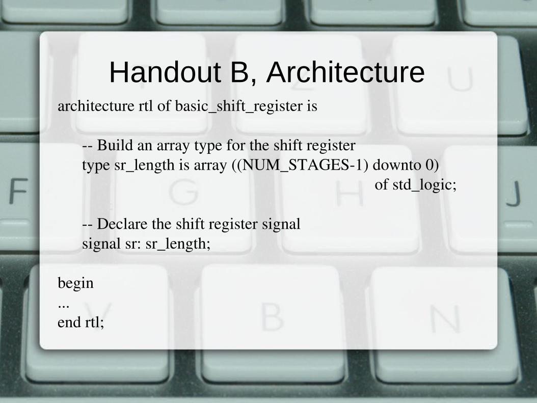
Handout B, Architecturearchitecture rtl of basic_shift_register is
Build an array type for the shift registertype sr_length is array ((NUM_STAGES1) downto 0)
of std_logic;
Declare the shift register signalsignal sr: sr_length;
begin...end rtl;

Handout B, Process
process (clk)begin
if (rising_edge(clk)) thenif (enable = '1') then
sr((NUM_STAGES1) downto 1) <= sr((NUM_STAGES2) downto 0);
sr(0) <= sr_in;end if;
end if;end process;

Handout C, Entity Declarationentity single_port_ram is
generic (
DATA_WIDTH : natural := 8;ADDR_WIDTH : natural := 6
);port (
clk : in std_logic;addr :in natural range 0 to 2**ADDR_WIDTH 1;data :in std_logic_vector((DATA_WIDTH1) downto 0);we : in std_logic := '1';q : out std_logic_vector((DATA_WIDTH 1) downto 0)
);end entity;

Handout C, Architecturearchitecture rtl of single_port_ram is
subtype word_t is std_logic_vector((DATA_WIDTH1) downto 0);
type memory_t is array(2**ADDR_WIDTH1 downto 0) of word_t;
signal ram : memory_t;signal addr_reg : natural range 0 to 2**ADDR_WIDTH1;
begin...end rtl;

Handout C, Processprocess(clk)
beginif(rising_edge(clk)) then
if(we = '1') thenram(addr) <= data;
end if;
Register the address for readingaddr_reg <= addr;
end if;end process;

Entity declaration
entity NAME_OF_ENTITY is [ generic generic_declarations);]
port (signal_names: mode type;
signal_names: mode type;
:
signal_names: mode type);
end [NAME_OF_ENTITY] ;
Port declaration (entity clause)● signal_name – user specified name
● mode – in, out, buffer, inout
● type
– bit, bit_vector (2 values)
– std_logic, std_ulogic, std_logic_vector, std_ulogic_vector (9 values)
– boolean (TRUE or FALSE)
– integer, real, character
– time (e.g. to simulate variable delay)

Behavioural Model (architecture)
architecture behavioural of MY_DEVICE is
begin the clauses below are concurrent
Y <= (not X and Y) or Z; combinational logic
process (clk) –sequential machines or comb. logic...
end process;
end behavioral;

RTL Model● RTL is a special class of behavioural model● Aimed at Mealy or Moore type FSM
favoured by designers because it is synthesisable!
● Registers● Functions (Boolean expressions or “if”)● Global clock, usually the positive edge

Structural Modelarchitecture structural of MY_DEVICE iscomponent AND2
port (in1, in2: in std_logic;out1: out std_logic);
end component;begin
I1: AND2 port map (X, Z, Y);I2: AND2 port map (Y, S, D);
end structural;
This model is also synthesisable. It can be mixed with RTL. Netlists are structural models.

Hierarchical Design● Several blocks – structural model● Some blocks include the others as
components● The components can be defined in the
same file as the high-level block● ...or they can be placed in separate files
and included into the project● All files in the project belong to “work”
library
Handout D, Hierarchy
● This is the test setup for our serial interfaces, where the transmitter and receiver are coupled.
● The encircled components are defined in the library “work”.
● Their files are included in the project, which makes them to belong to this library.
● There are also other ways of doing it...

Libraries and Packages
library ieee;use ieee.std_logic_1164.all;use ieee.std_logic_arith.all;use ieee.std_logic_unsigned.all;
library SYNOPSYS;use SYNOPSYS.attributes.all;
Using them is simple

Creating a New Package
● Choose a library to add the package● “work” is the default project library● Declare the package● Declare the body of the package● You will not need it in this coursework...

Lexical Elements (home task)
● Identifiers● Keywords● Numbers● Characters, bits, bit strings
How to understand these?
“This is a “”String””.”
2#1001_1101_1100_0010#

Signals
● Declared outside the process● Updated after assignment execution with
some delay (perhaps, infinitely small)● Unspecified delay is “delta delay”, very
short, impossible to see in waveforms.● This delay is important for concurrent
assignments. Why? Examples.
signal list_of_signal_names: type [ := initial value] ;

Variables
● declared in a process● local to the process● updated without delay● updated with a variable assignment
statement A := B;
variable list_of_variable_names: type [ := initial value] ;

Constants
● Used when one needs a value that never changes during execution
● Can be declared for the whole architecture or locally inside a process
constant list_of_name_of_constant: type [ := initial value] ;

Home Task● Obtain the reference materials from the list● Visit the web sites of Altera and Xilinx and
find descriptions of the architectures of their FPGA products.
● Review the examples given in the handouts● Read about the lexical elements of VHDL● Find RS232 interface, signals, protocol● Find reference materials on FIR filters