eedf f ti i pleedf formation in plasmas - ispc … · plasma consists of bulk (()p (p )neutral)...
TRANSCRIPT

EEDF F ti i PlEEDF Formation in Plasmas(ISPC-18, IUPAC Summer School, Aug. 23, 2007)
Kenichi NanbuProfessor Emerit s Tohok Uni ersit JAPANProfessor Emeritus, Tohoku University, JAPAN
1
OutlineOutline
1. Introduction
Definition of EEDF
Two-temperature Maxwellian
2 EEDF from PIC/MC2. EEDF from PIC/MC
3. EEDF of RF Ar Plasmas
Effect of pressure
Effect of frequency
Effect of secondary electron emission coefficient
ff f i iEffect of position
4. EEDF of RF CF4 Plasmas
Effect of pressureEffect of pressure
Effect of frequency
Effect of secondary electron emission coefficient
2Acknowledgements
1 Introduction1. Introduction
Homo sapiens peaceHomo sapiens-peaceBalance of male and femaleStop killing people by peace keepingStop killing people by peace keeping
Plasma-sheathBalance of positive and negative species (bulk)Balance of positive and negative species (bulk)Stop killing electrons by sheath formation (sheath)
3
Plasma consists of bulk(neutral) plus sheath(positive)( ) p (p )
In DC, bulk has a potential hill with a flat top.Electrons cannot go down the hillElectrons cannot go down the hill.Discharge is self-sustained.
Definition of EEDF
N : electrons in volume element dVN : electrons in volume element dV: number of electrons inεεϕ dN )( ),( εεε d+
1)(∫∞
d 1)(0
=∫ εεϕ d
⎟⎞
⎜⎛2 εε
⎟⎟⎠
⎞⎜⎜⎝
⎛−=
e2/3
eM exp
)(
2)(
kTkT
εεπ
εϕ (equilibrium)
4Te: electron temperature

)( εεϕ
e
const.)(
lnkT
εεεϕ
−= (equilibrium)
Measure EEDF(lhs) → obtain Te
Electron density : ne = N /dVy e
Do not confuse !
)eV(/)(:EEDF -3/2εεϕ
)eVm( / )(:EEPF
)eV(/ )( :EEDF3/2-3-
e
εεϕ
εεϕ
n
Velocity space and VDFvv dNf )( : number of electrons in atvd vvv dNf )( : number of electrons in at
zyx dvdvdvd =v
vd v
∫∞
51)( =∫
∞
∞−vv df
Mean velocity (drift velocity)
df∫∞
)( vvvv df∫ ∞−= )(
Electron temperature:Te13
vvvv dfmkT ∫∞
∞−−= )()(
2
1
2
3 2e
11∫∞ 22 )(
2
1)(
2
1vvv mdfvm −= ∫
∞
∞−
( )m ( )22e )(
3v−= v
k
mT
Of i li ibl b f i2)(
⎞⎛⎞⎛ 22/3
Often, is negligible, but never so for ionDistribution of speed or
2)(vv v
⎟⎟⎠
⎞⎜⎜⎝
⎛−⎟
⎠⎞
⎜⎝⎛=
kT
vv
kT
mv
2exp
24)(
22
2/3
ππχ (equil.)
6)()(,2
1 2 εϕχε →= vmv

Why is EEDF important?Various reactions occur in processing plasma.Rate constant kr is obtained from EEDF.
e- + Ar → e- + Ar+ + e-
εεϕεσε dk )()(2
∫∞
(ionization)
EEDF governs rate constant
εεϕεσε
dm
k )()(izizth∫= (ionization)
EEDF governs rate constant.
7
If equilibrium is assumed, the rate obtained is far from true.Example : Ar, rf plasma, f =13.56MHz, p = 200mTorr, γ=0.1
5
5
0
(-3/
2)]}
Raw Data
T1 = 1.840 eV
T2 = 0.8929 eV
-10
-5
EE
DF
[eV
^(
-15
ln{E
-20
0 10 20 30 40 50
Energy (eV)
8

EEDF is two-temperature Maxwellian.
⎧ f)( T
⎩⎨⎧
>≤
=c2M2
c1M1
for),(
for),()(
εεεϕεεεϕ
εϕ
Tc
Tc
T1=1.840eV, T2=0.8929eV, εc=13.0eV
⎩ c2M2 )(ϕ
9
Since εi =15 76eV > ε EEDF for ε> ε governs the rate kiSince εiz 15.76eV > εc , EEDF for ε> εc governs the rate kiz.
Coefficients c1, c2
1)()(cε
∫∫∞
dTdT 2M210 M1
at)()(
1),(),(c
εεεϕεϕ
εεϕεεϕε
==
=+ ∫∫TcTc
dTcdTc
c2M21M1 at ),(),( εεεϕεϕ == TcTc
dttt f)(1
)( 222 π+∫
∞
c = 0 999094
xxxdtttx
erfc4
)exp(2
)exp( 222 +−=−∫c1 = 0.999094c2 = 607.048
{rate const. for equil. T1}
{rate const for two-temp}= 26.0
10
{rate const. for two-temp}

2. EEDF from PIC/MC
Energy 221 mv=ε
Velocity v is governed by the Boltzmann equation.Velocity distribution function f (v, x, t ) of electrons
∂∂∂ q)()()()(
⎞⎛⎞⎛∂∂
⋅×++∂∂
⋅+∂∂
nfm
qnfnf
t vBvE
xv
inelel
)()(⎟⎠⎞
⎜⎝⎛
∂∂
+⎟⎠⎞
⎜⎝⎛
∂∂
=t
nf
t
nf
Number of electrons in dv×dx is nf (v, x, t ) dvdxB eq shows :
inelel ⎠⎝⎠⎝
B eq shows : E-field, B-field, elastic coll., and inelastic coll. govern EEDF
PIC/MC : solution method of B equation
11
qRef : K. Nanbu, IEEE Trans, Plasma Science, Vol.28(2000)971-990.
PIC/MC code:(株)計算力学研究センター(www.rccm.co.jp)
Main ideaGrades of N(=1000) students{x1, x2, ・・・ , xN}idea of distribution, e.g.
2 ⎤⎡ ⎞⎛)Maxwellian(
2
1exp
2
1)(
2
D σπσ
xxxf
⎥⎥⎦
⎤
⎢⎢⎣
⎡⎟⎠⎞
⎜⎝⎛ −
−=
deviation standard:
mean:
σ
x
exact expression
∑ −= )(1
)(E xxN
xfN
iδ
∫ ∫
∑∞
∞−
∞
∞−
=
== 1)()(
)()(
ED
1E
dxxfdxxf
Nf
ii
Relation between fD and fE
High fD → {x1, x2, ・・・} is dense
∫ ∫∞ ∞
12
g fD { 1 2 }Low fD → {x1, x2,・・・} is sparse

f (v, x, t ) of B eq is like fD
fE for B eq is expressed as
n ∑=N
tttf 33 ))(())(()( xxvvxv δδn
We can derive the laws governing the set {xi(t ), vi(t ): i=1,2,・・・}
∑=
−−=i
ii tttf1
E ))(())((),,( xxvvxv δδ
g g { i( ), i( ) , , }from B eq.
The laws determine{xi(t +Δt ), vi(t +Δt )}
using a given {xi(t ), vi(t )}The law is partly deterministic partly stochasticThe law is partly deterministic, partly stochastic.Let us consider electrons in E-field.Collision probability of electron in (t ,t +Δt ) isp y ( , )
b d i d)/2(
tvNP Δ= )(Tgc εσ
13
Ng:gas number density, v : speed at t:energy at t, :total collision cross section
)/2( mε=ε Tσ
In case of Pc=1/6, play dice.I f lli i (t +Δt ) d (t +Δt ) d t i dIn case of no collision, xi(t +Δt ) and vi(t +Δt ) are determined
by solving the equation of motion
)( td i E
v
The equation is coupled with the field equation
),( tqdt
m ii xE=
th h 0ερ
=⋅∇ E
throughspecies):( jnq
jjj ∑=ρ
where nj is a functional of sets {xi}j
If a collision occurs, we determine
j
(1) type of collision(elastic, exciting, ionizing)(2) post-collision velocity
These are the theoretical basis of PIC/MC14
These are the theoretical basis of PIC/MC.

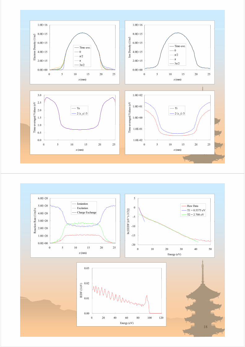
3. EEDF of RF Ar Plasmas
General structure of Ar rf dischargeelectrode spacing = 25.4mm (fixed)p =25mTorrf =13 56MHzf =13.56MHzγ=0.1Vrf =200VVrf 00V
φ(z,t), Ez(z,t) ,ρ(z,t), ・・・
15
3.0E+02 6.0E+04
0.0E+00
1.0E+02
2.0E+02
ntia
l (V
)
0.0E+00
3.0E+04
(V/m
)
-2.0E+02
-1.0E+02
0.0E 00
Pot
en Time-ave.
0
π/2
π
3π/2
-3.0E+04
0.0E 00
Ez
(
0
π/2
π
3π/2
-3.0E+02
0 5 10 15 20 25
z (mm)
3π/2-6.0E+04
0 5 10 15 20 25
z (mm)
1.5E-04
2.0E-04
3 5 0E+05
1.0E+06
m3)
5.0E-05
1.0E-04
rge
Den
sity
(C
/m3
0
π/2
π
3π/2
0.0E+00
5.0E+05
rbed
Pow
er (
W/m
0
-5.0E-05
0.0E+00
0 5 10 15 20 25
Cha
r
-1.0E+06
-5.0E+05
0 5 10 15 20 25
Abs
or π/2
π
3π/2
16
0 5 10 15 20 25
z (mm)
0 5 10 15 20 25
z (mm)
1.0E+16 1.0E+16
6.0E+15
8.0E+15D
ensi
ty (
1/m
3
Time-ave.
6.0E+15
8.0E+15
sity
(1/
m3)
Time-ave.
2.0E+15
4.0E+15
Ele
ctro
n D Time ave.
0
π/2
π
3π/2
2.0E+15
4.0E+15
Ion
Den 0
π/2
π
3π/2
0.0E+00
0 5 10 15 20 25
z (mm)
0.0E+00
0 5 10 15 20 25
z (mm)
2.5
3.0
(eV
1 0E+01
1.0E+02
(eV
1 0
1.5
2.0
aver
aged
Val
ues
(
Te
2〈ε_e〉/3
1.0E+00
1.0E+01
aver
aged
Val
ues
(
Ti
2〈ε_i〉/3
0.0
0.5
1.0
0 5 10 15 20 25
Tim
e-a
1.0E-02
1.0E-01
0 5 10 15 20 25
Tim
e-a
17
0 5 10 15 20 25
z (mm)
0 5 10 15 20 25
z (mm)
6.0E+20 5
3.0E+20
4.0E+20
5.0E+20
Rat
e (1
/m3/
s)
Ionization
Excitation
Charge Exchange
-5
0
[eV
^(-3
/2)]
}
Raw Data
T1 = 0.5375 eV
T2 = 2.708 eV
1.0E+20
2.0E+20
3.0E 20
Rea
ctio
n R
-15
-10
ln{E
ED
F [
0.0E+00
0 5 10 15 20 25
z (mm)
-20
0 10 20 30 40 50
Energy (eV)
0.03
0 01
0.02
IED
F (
1/eV
)
0.00
0.01
0 20 40 60 80 100 120
18
0 20 40 60 80 100 120
Energy (eV)
Mechanism of electron heatingDrift velocity of electron at sheath edgeApplied voltage tV ωϕϕ == sinApplied voltage Sheath thickness Expanding sheath accelerates electrons.
tV ωϕϕ == ,sinrf
)sin1(max21 ϕδ −≅
)( 23
21 ππϕ ~=Expanding sheath accelerates electrons.)( 22ϕ
19
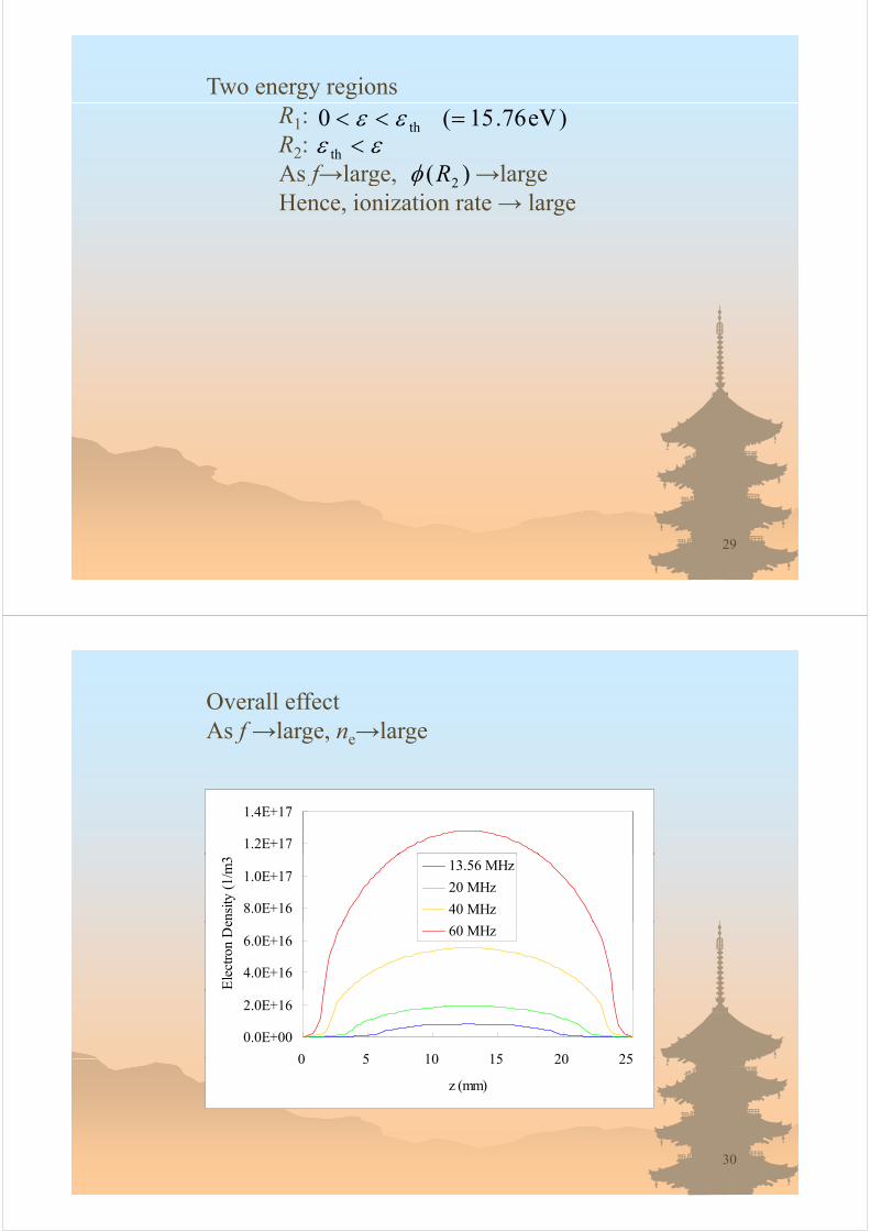
Ar, 13.56 MHz, 25 mTorr, γi=0
6.0E 15
(1/m ← Sampling position of EEDF and
drift velocity W
4.0E+15
Den
sity
Time-ave.
drift velocity Wz
Forward
B k d
ctro
n D e ve.
0
π/2
Backward
2.0E+15Ele
c π/2
π
3 /2
0.0E+00
3π/2
0 5 10 15
z (mm)20
z (mm)

Ar, 13.56 MHz, 25 mTorr, γi=0
m) Forward
0.0E+00z
(V/m Backward
Ez
0
π/2-3.0E+04
π/2
π
-6 0E+04
3π/2
6.0E+04
0 5 10Sampling position of EEDF and
21z (mmSampling position of EEDF and drift velocity Wz
Ar, 13.56 MHz, 25 mTorr, γi=0
1.0E-02
1.0E-01
1.0E+00
2)]
Forward
Backward1.0E-04
1.0E-03
1.0E-02
1.0E-01
1.0E+00
ED
F [
eV^(
-3/2
)]
Forward
Backward
1.0E-07
1.0E-06
1.0E-05
1.0E-04
1.0E-03
EE
DF
[eV
^(-3
/2 Backward
1.0E-07
1.0E-06
1.0E-05
0 10 20 30 40
Energy (eV)
EE
2.0E+05
3.0E+05
)
.0 07
0 10 20 30 40
Energy (eV)
1.0E+05
|Wz|
(m
/s)
Forward
Backward
0.0E+00
0.00 0.25 0.50 0.75 1.00
Normalized Phase t/T
1 0E 01
1.0E+00 1.0E+00
π/2 π 3π/2
1.0E-05
1.0E-04
1.0E-03
1.0E-02
1.0E-01
EE
DF
[eV
^(-3
/2)]
Forward
Backward
1.0E-05
1.0E-04
1.0E-03
1.0E-02
1.0E-01
EE
DF
[eV
^(-3
/2)]
Forward
Backward
221.0E-07
1.0E-06
0 10 20 30 40
Energy (eV)
1.0E-07
1.0E-06
0 10 20 30 40
Energy (eV)

Effect of pressureAr, p =25, 50, 100, 150, 200mTorrf =13.56MHzVrf =200VVrf 200Vγ=0.1z =L/2 (L=25.4mm) for EEDF
1.0E+01 3.0
1.0E-03
1.0E-01
V^(
-3/2
)]
25 mTorr
50 mTorr
100 mTorr
150 mTorr
200 mTorr
2.0
2.5
(eV
)
T1
T2
1.0E-07
1.0E-05
EE
DF
[eV 200 mTorr
0.5
1.0
1.5
T1,
T2
1.0E-09
0 10 20 30 40 50
Energy (eV)
0.0
0 50 100 150 200 250
Pressure (mTorr)
23
Consider two-temperature modelT1=low energy temperatureT2=high energy temperatureAs p→large, T1→large and T2→smallAs p large, T1 large and T2 small
T1 governs overall temperature Te
As p→large, Te→large
4
V
25 mTorr
50 mTorr
2
3
empe
ratu
re (
eV
50 mTorr
100 mTorr
150 mTorr
200 mTorr
1
Ele
ctro
n T
e
0
0 5 10 15 20 25
z (mm)
24

Two regions for εεϕεφ )()( =)61(0R1:
R2:As p→large, →small
)eV76.15(0 th =<< εε εε <th
)( 2RφAs p large, smallHence, ionization frequency per electron → small
But, as p→large, e--Ar collision frequency → largeO ll ff i
)( 2Rφ
Overall effect is:As p increases, ne→inc →dec →inc →inc
1.0E-01
1.0E+01
2)]
25 mTorr
50 mTorr
100 mTorr1.5E+16
2.0E+16
(1/m
3
25 mTorr50 mTorr100 mTorr150 mTorr200 mTorr
1.0E-05
1.0E-03
EE
DF
[eV
^(-3
/2
150 mTorr
200 mTorr
5 0E+15
1.0E+16
Ele
ctro
n D
ensi
ty (
1.0E-09
1.0E-07
0 10 20 30 40 50
0.0E+00
5.0E+15
0 5 10 15 20 25
E
25
Energy (eV) z (mm)
Effect on IEDF at electrode
0.10
0.08
0.10
25 mTorr
50 mTorr
0.04
0.06
ED
F (
1/eV
) 100 mTorr
150 mTorr
200 mTorr
0.02
0.0IE
0.00
0 20 40 60 80 100 120
Energy (eV)
26
Energy (eV)

Effect of frequencyAr, f=13.56, 20, 40, 60MHzp =25mTorrV =200VVrf =200Vγ= 0.1z =L/2 (L=25.4mm) for EEDFz L/2 (L 25.4mm) for EEDF
1 0E+01 3 0
1 0E-03
1.0E-01
1.0E+01
(-3/
2)]
13.56 MHz
20 MHz
40 MHz
60 MHz2.0
2.5
3.0
V)
1.0E-07
1.0E-05
1.0E-03
EE
DF
[eV
^(
60 MHz
0 5
1.0
1.5
T1,
T2
(eV
T1
T2
1.0E-09
1.0E 07
0 10 20 30 40 50
Energy (eV)
0.0
0.5
0 10 20 30 40 50 60 70
Frequency (MHz)
T2
27
gy ( ) q y ( )
As f→large, T1→large and T2→smallT1 governs overall temperature Te
As f→large, Te→large
4
3
pera
ture
(eV
13.56 MHz
20 MHz
40 MHz
60 MHz
1
2
Ele
ctro
n T
emp
0
0 5 10 15 20 25
E
z (mm)
28
Two energy regionsR1: R2:As f→large →large
)eV76.15(0 th =<< εεεε <th
)(RφAs f→large, →largeHence, ionization rate → large
)( 2Rφ
29
Overall effectAs f →large, ne→large
1.2E+17
1.4E+17
8.0E+16
1.0E+17
ensi
ty (
1/m
3 13.56 MHz
20 MHz
40 MHz
4.0E+16
6.0E+16
Ele
ctro
n D
e
60 MHz
0.0E+00
2.0E+16
0 5 10 15 20 250 5 10 15 20 25
z (mm)
30

Effect of γ, secondary electron emission coefficientA 0 0 1Ar, γ=0, 0.1p =25mTorrV f =200VVrf 200Vz =L/2 (L=25.4mm)EEDF has a high energy tail of secondary electrons.Hence, ionization rate increases.Therefore, ne increases.
1.0E-01
1.0E+01
]
γi = 0
i 0 1 1 0E+20
1.2E+20
1.4E+20
m3/
s
1.0E-07
1.0E-05
1.0E-03
EE
DF
[eV
^(-3
/2) γi = 0.1
4 0E+19
6.0E+19
8.0E+19
1.0E+20
niza
tion
Rat
e (1
/m
γi = 0
i 0 1
1.0E-11
1.0E-09
0 50 100 150 200 250
E
0.0E+00
2.0E+19
4.0E+19
0 5 10 15 20 25
Ion γi = 0.1
31
0 50 100 150 200 250
Energy (eV) z (mm)
Effect of position z on EEDFγ=0z = 5.8mm (sheath edge) z =L/2 (center of bulk)z =L/2 (center of bulk)Sheath oscillation gives energy to electrons.
1.0E+02
1.0E-02
1.0E+00
V^(
-3/2
)]
Bulk
Sheath
1 0E 08
1.0E-06
1.0E-04
EE
DF
[eV
1.0E-10
1.0E-08
0 10 20 30 40 50
32
Energy (eV)

Ar, 13.56 MHz, 25 mTorr, γi=0
π → 3π/2 では2 < ε < 25 eV 電子数増加顕著
2 V 電子数減少顕著
1.0E-01
1.0E+00
0
π/2
ε < 2 eV 電子数減少顕著
加熱された!
1.0E-02
^(-3
/2)]
π/2
π
3π/2
1 0E-04
1.0E-03
ED
F [
eV^
1.0E-05
1.0E-04EE
π/2 → π では,高エネルギー領域側の電子数増加が顕著
1.0E-06
0 5 10 15 20 25 30
領域側の電子数増加が顕著
33Energy (eV)
Ar, 13.56 MHz, 25 mTorr, γi=0
6 0E+15
(
6.0E+15
Den
sity
04.0E+15
ctro
n D 0
π/2
2.0E+15Ele
c π
3π/2π/2 π において加熱される電子
0.0E+00
π/2 → π において加熱される電子.電界も強いので高エネルギーを有する.
0 5 10 15
( )π → 3π/2 において加熱される低エネルギー(<2eV)電子 電界が弱 加熱は比較的小さ
34
z (mm)電子.電界が弱いので,加熱は比較的小さい.

Ar, 13.56 MHz, 25 mTorr, γi=0
m)
0 → πの位相では電界が無く,バルクと同等であるために2eV以下の低エネルギー電子が多い.π → 3π/2 では加熱されるが,電界が弱いので,
0.0E+00z
(V/m
π 3π/2 では加熱されるが,電界が弱いので,加熱は比較的小さい.
Ez
0
π/2-3.0E+04
π/2
π
-6 0E+04
3π/2
6.0E+04
0 5 10π/2の位相でシース中に侵入した電子が 今度は
35z (mm)π/2の位相でシ ス中に侵入した電子が,今度はπ/2 → π でバルク側に,高電界で加速されるために,高エネルギーを有する.
4. EEDF of RF CF4 plasmas4 p
CF4 is used in plasma etchingS i i CF lSpecies in CF4 plasma
e-, F-, CF3-, F+, C+, CF+, CF2
+, CF3+
Electron-CF4 collision cross section (by H. Ito)4 ( y )
101
102
2 )
Qm
Qv3
100
101
n (1
0-16 c
m2
Qv4
Qv3
Qv2×3
Qdn
Qi(CF3+)
Qi(C+)
10-1
ross
-Sec
tion
Qv2×3
Qi(CF2+)
Qi(C )
Qi(F+)
10-2
Cr
Q i(CF+)
Qa(F-)
Qa(CF3- )
3610-2 10-1 100 101 102 103
Electron Energy (eV)
10-3

Structure of rf CF4 plasmap(CF4) =25mTorrf =13.56MHzVrf =200VVrf 200Vγ=0.1z =L/2 (L=25.4mm) for EEDFSh h i hi kSheath is thick.
3.0E+04
6.0E+04
m)
3.0E+04
6.0E+04
m)
Ar CF4
-3.0E+04
0.0E+00
Ez
(V/m
0
π/2
π-3.0E+04
0.0E+00
Ez
(V/m
0
π/2
π
-6.0E+04
0 5 10 15 20 25
z (mm)
π
3π/2
-6.0E+04
0 5 10 15 20 25
z (mm)
π
3π/2
37
Electron density is strongly time-modulated.Order of densities
CF3+ > F- > CF3
- > e- > CF2+
4.0E+14
05.0E+15
CF3+
2.0E+14
3.0E+14
n D
ensi
ty (
1/m
3 π/2
π
3π/2
2 0E 15
3.0E+15
4.0E+15
nsity
(1/
m3)
CF2+
CF+
C+
F+
F
0.0E+00
1.0E+14Ele
ctro
n
0 0E+00
1.0E+15
2.0E+15
Den F-
CF3-
Electron
0 5 10 15 20 25
z (mm)
0.0E+00
0 5 10 15 20 25
z (mm)
38
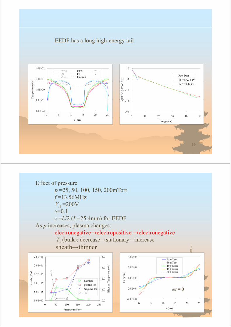
EEDF has a long high-energy tail
1.0E+01
1.0E+02
V)
CF3+ CF2+ CF+C+ F+ F-CF3- Electron
-5
0
2)]}
Raw Data
T1 =0.9236 eV
1 0E 01
1.0E+00
Tem
pera
ture
(eV
-10
{EE
DF
[eV
^(-3
/2
T2 = 4.543 eV
1.0E-02
1.0E-01
0 5 10 15 20 25-20
-15
0 10 20 30 40 50
ln{
z (mm) Energy (eV)
39
Effect of pressurep =25 50 100 150 200mTorrp 25, 50, 100, 150, 200mTorrf =13.56MHzVrf =200Vγ=0.1z =L/2 (L=25.4mm) for EEDF
As p increases, plasma changes:As p increases, plasma changes:electronegative→electropositive →electronegativeTe (bulk): decrease→stationary→increaseh h hisheath→thinner
2.5E+16 4.0 4.0E+0425 mTorr50 mTorr
1.5E+16
2.0E+16
sity
(1/
m3)
2.0
3.0
empe
ratu
re (
eV
Electron0.0E+00
2.0E+04
Ez
(V/m
)
50 mTorr100 mTorr150 mTorr200 mTorr
5.0E+15
1.0E+16
Den
s
1.0
Ele
ctro
n TElectron
Positive Ion
Negative Ion
Te
-4 0E+04
-2.0E+04
E
ωt = 0
40
0.0E+00
0 50 100 150 200 250
Pressure (mTorr)
0.0 -4.0E+04
0 5 10 15 20 25
z (mm)

As p increases,electron density: increase→decreaseelectron density: increase→decreaseelectron temperature(sheath):opposite to bulk
8.0E+15
1.0E+16
/m3
25 mTorr
50 mTorr
100 T15
20
(eV
25 mTorr
50 mTorr
4.0E+15
6.0E+15
ctro
n D
ensi
ty (
1/m
100 mTorr
150 mTorr
200 mTorr 10
tron
Tem
pera
ture
100 mTorr
150 mTorr
200 mTorr
0.0E+00
2.0E+15
0 5 10 15 20 25
Ele
0
5
0 5 10 15 20 25
Ele
ctz (mm) z (mm)
41
density(CF3+ , F- , CF3
- )→increase
2.5E+16
3.0E+16
m3)
25 mTorr
50 mTorr
100 mTorr
150 mTorr
1.0E+16
1.5E+16
2.0E+16
CF
3+ D
ensi
ty (
1/m
200 mTorr
0.0E+00
5.0E+15
0 5 10 15 20 25
C
z (mm)
3.0E+1625 mTorr
50 mTorr3.0E+16
25 mTorr
50 mTorr
1.5E+16
2.0E+16
2.5E+16
nsity
(1/
m3)
100 mTorr
150 mTorr
200 mTorr
1.5E+16
2.0E+16
2.5E+16
ensi
ty (
1/m
3)
100 mTorr
150 mTorr
200 mTorr
5.0E+15
1.0E+16F-
Den
5.0E+15
1.0E+16
CF
3- D
e
42
0.0E+00
0 5 10 15 20 25
z (mm)
0.0E+00
0 5 10 15 20 25
z (mm)

temperature(CF3+)→increases near the electrode(E-field)
temperature(F- CF3- )→decrease in the sheath(collisional loss)temperature(F , CF3 )→decrease in the sheath(collisional loss)
8
10
V)
25 mTorr
4
6
8
Tem
pera
ture
(eV 50 mTorr
100 mTorr
150 mTorr
200 mTorr
0
2CF
3+
0 5 10 15 20 25
z (mm)
825 T
8
4
6
atur
e (e
V)
25 mTorr
50 mTorr
100 mTorr
150 mTorr
200 mTorr4
6
erat
ure
(eV
)
25 mTorr
50 mTorr
100 mTorr
150 mTorr
200 mTorr
2
4
F-
Tem
pera
2
4
CF
3- T
empe 200 mTorr
430
0 5 10 15 20 25
z (mm)
0
0 5 10 15 20 25
z (mm)
As p increases,two-temperature: T1→sudden increase at 150mTorr
(transition to electronegative)T2→small change, compared with T1
1 0E 01
1.0E+01 25 mTorr
50 mTorr
100 mTorr 25.0
30.0
1 0E-05
1.0E-03
1.0E-01
DF
[eV
^(-3
/2)]
100 mTorr
150 mTorr
200 mTorr
15.0
20.0
25.0
1, T
2 (e
V)
1.0E-09
1.0E-07
1.0E 05
EE
D
0 0
5.0
10.0
T
T1
T2
0 10 20 30 40
Energy (eV)
0.0
0 50 100 150 200 250
Pressure (mTorr)
44

Effect of frequencyf =13.56, 20, 40, 60MHzp =25mTorrV =200VVrf =200Vγ=0.1z =L/2 (L=25.4mm) for EEDFz L/2 (L 25.4mm) for EEDF
As f increases, plasma changes:sheath→thinner
6.0E+0413.56 MHz
20 MHz
0.0E+00
3.0E+04
Ez
(V/m
)
40 MHz
60 MHz
-6.0E+04
-3.0E+04
0 5 10 15 20 25
ωt = 0
45
0 5 10 15 20 25
z (mm)
As f increasesAs f increases, electronegative → electropositive plasmaOnly at 13.56MHz, plasma is electronegative!O y 3.56 , p s s e ec o eg ve!
1.0E+17
3.0
4.0
e (e
V
1.0E+16
Den
sity
(1/
m3)
2.0
n T
empe
ratu
re
Electron
1 0E+14
1.0E+15D
0 0
1.0
Ele
ctro
ElectronPositive IonNegative IonTe
1.0E+14
0 10 20 30 40 50 60 70
Frequency (MHz)
0.0
46

electronegative→electropositive at f=20MHzelectronegative→electropositive at f 20MHz
13.56 MHz 60 MHz
8.0E+16CF3+ CF2+ CF+C+ F+ F-CF3- Electron
4.0E+15
5.0E+15
CF3+
CF2+
4.0E+16
6.0E+16
Den
sity
(1/
m3)
2.0E+15
3.0E+15
Den
sity
(1/
m3)
CF2
CF+
C+
F+
F-
0.0E+00
2.0E+16
0 5 10 15 20 25
D
0.0E+00
1.0E+15
0 5 10 15 20 25
D CF3-
Electron
0 5 10 15 20 25
z (mm)
0 5 10 15 20 25
z (mm)
47
As f increases,electron and positive ion increase,negative ion density slightly changes in bulknegative ion density slightly changes in bulk.
8.0E+16 13.56 MHz (×10)
20 MHz
40 MHz
8.0E+16
m3
13.56 MHz
20 MHz
40 MHz
4.0E+16
6.0E+16
on D
ensi
ty (
1/m
3
60 MHz
4.0E+16
6.0E+16
Ion
Den
sity
(1/
m
60 MHz
0.0E+00
2.0E+16Ele
ctro
0.0E+00
2.0E+16
Pos
itive
0 5 10 15 20 25
z (mm)
0 5 10 15 20 25
z (mm)
6.0E+15 13.56 MHz
20 MHz
3 0E+15
4.0E+15
5.0E+15
Den
sity
(1/
m3
20 MHz
40 MHz
60 MHz
1.0E+15
2.0E+15
3.0E+15
Neg
ativ
e Io
n
48
0.0E+00
0 5 10 15 20 25
z (mm)
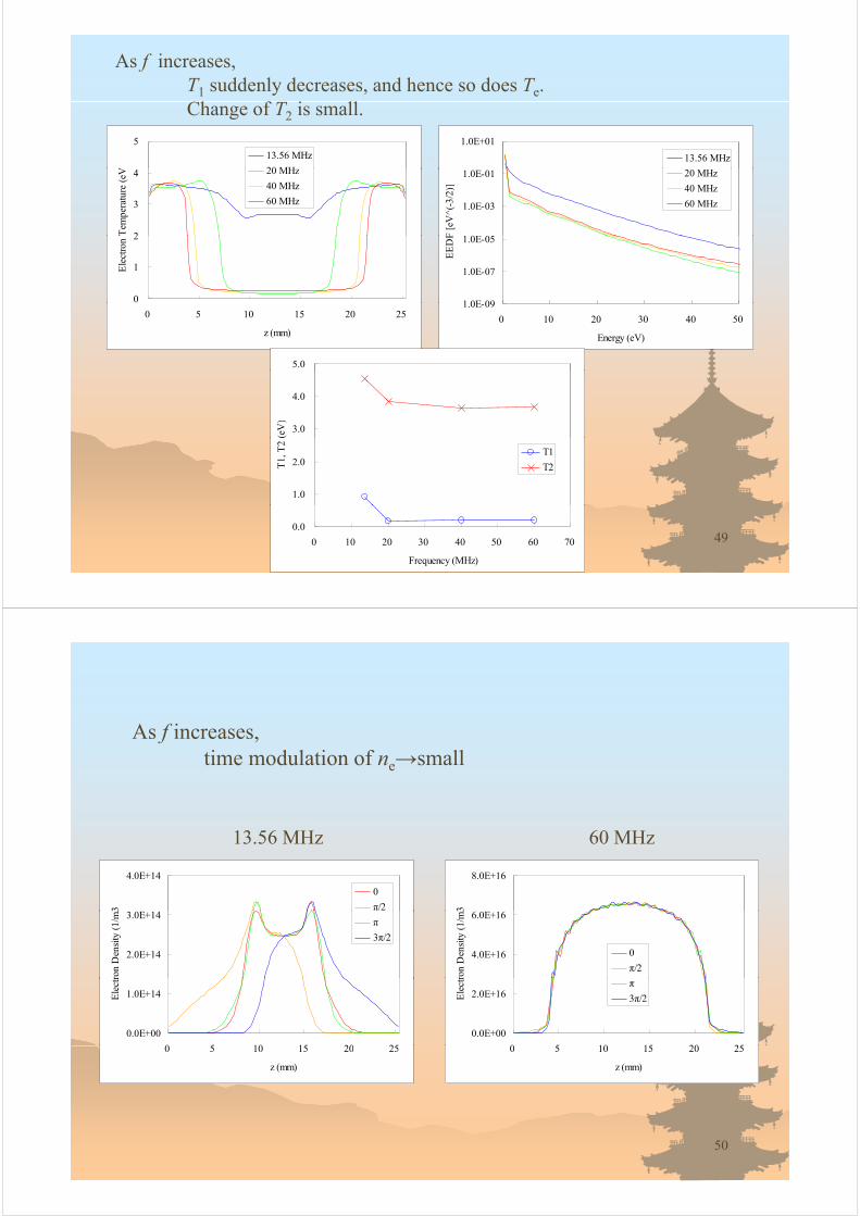
As f increases,T1 suddenly decreases, and hence so does Te.Ch f i llChange of T2 is small.
5
V
13.56 MHz
20 MH
1.0E+01
13.56 MHz
2
3
4
Tem
pera
ture
(eV 20 MHz
40 MHz
60 MHz
1 0E 05
1.0E-03
1.0E-01
F [
eV^(
-3/2
)]
20 MHz
40 MHz
60 MHz
0
1
2
Ele
ctro
n
1 0E 09
1.0E-07
1.0E-05
EE
DF
0 5 10 15 20 25
z (mm)
1.0E-09
0 10 20 30 40 50
Energy (eV)
5.0
3.0
4.0
(eV
)
1.0
2.0T1,
T2
T1
T2
490.0
0 10 20 30 40 50 60 70
Frequency (MHz)
As f increases,time modulation of ne→small
13.56 MHz 60 MHz
4.0E+14
3
0
π/2
8.0E+16
3
2.0E+14
3.0E+14
ron
Den
sity
(1/
m3
π
3π/2
4.0E+16
6.0E+16
ron
Den
sity
(1/
m3
0
π/2
0.0E+00
1.0E+14
0 5 10 15 20 25
Ele
ctr
0.0E+00
2.0E+16
0 5 10 15 20 25
Ele
ctr
π
3π/2
0 5 10 15 20 25
z (mm)
0 5 10 15 20 25
z (mm)
50

Comparison with ArO ll T d d (CF )Overall Te → decrease one order (CF4)cf. → increase by 2.6 times (Ar)
4.0 4.0
13.56 MHz 60 MHz
2 0
3.0
ed V
alue
s (e
V
2 0
3.0
ed V
alue
s (e
V
1.0
2.0
Tim
e-av
erag
e
Te
2〈ε_e〉/31.0
2.0
Tim
e-av
erag
e
Te
2〈ε_e〉/3
0.0
0 5 10 15 20 25
z (mm)
0.0
0 5 10 15 20 25
z (mm)
51
Effect of γ, secondary electron emission coefficientCF4 0 0 1CF4γ=0, 0.1p(CF4) =25mTorrVrf =200Vz =L/2 (L=25.4mm)
EEDF has a high energy tail of secondary electrons.g gy yHence, ionization rate increases,Therefore, ne increases.
2 0E+14
2.5E+14
3.0E+14
(1/m
3 1.0E-01
1.0E+01
2)]
γi = 0
γi = 0.1
1.0E+14
1.5E+14
2.0E+14
Ele
ctro
n D
ensi
ty (
γi = 0
γi 0 1
1.0E-05
1.0E-03
EE
DF
[eV
^(-3
/2
γ
0.0E+00
5.0E+13
0 5 10 15 20 25
E γi = 0.1
1.0E-09
1.0E-07
0 50 100 150 200 250
52
z (mm) Energy (eV)

As γ increases,electrons contributing to electron attachment (5-9 eV) decrease andelectrons contributing to electron attachment (5 9 eV) decrease, and hence negative ion decreases, so does positive ion.
1.0E+00
1 0E-04
1.0E-02
eV^(
-3/2
)]
γi = 0
γi = 0.1
1.0E-06
1.0E-04
EE
DF
[e
6 0 1 6 0E 15
1.0E-08
0 10 20 30 40 50 60
Energy (eV)
4.0E+15
5.0E+15
6.0E+15
nsity
(1/
m3 γi = 0
γi = 0.14.0E+15
5.0E+15
6.0E+15
ensi
ty (
1/m
3
γi = 0
γi = 0.1
1.0E+15
2.0E+15
3.0E+15
Pos
itive
Ion
Den
1.0E+15
2.0E+15
3.0E+15
Neg
ativ
e Io
n D
e
530.0E+00
0 5 10 15 20 25
z (mm)
0.0E+00
0 5 10 15 20 25
z (mm)
For larger γ,T1 becomes smaller and hence so does TT1 becomes smaller, and hence so does Te.
1.0E+00 5.0
1.0E-04
1.0E-02
F [
eV^(
-3/2
)]
γi = 0
γi = 0.1
2 0
3.0
4.0
, T2
(eV
)
T1
1 0E 08
1.0E-06
EE
DF
0 0
1.0
2.0T1
T2
1.0E-08
0 10 20 30 40 50 60
Energy (eV)
0.0
0.0 0.1
γi
5
3
4
mpe
ratu
re (
eV
1
2
Ele
ctro
n T
em
γi = 0
γi = 0.1
54
0
0 5 10 15 20 25
z (mm)
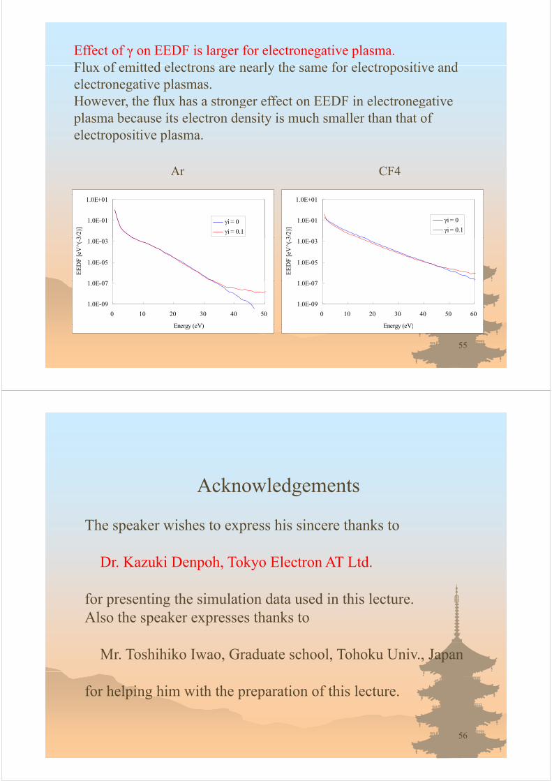
Effect of γ on EEDF is larger for electronegative plasma.Fl of emitted electrons are nearl the same for electropositi e andFlux of emitted electrons are nearly the same for electropositive and electronegative plasmas.However, the flux has a stronger effect on EEDF in electronegative g gplasma because its electron density is much smaller than that of electropositive plasma.
Ar CF4
1.0E-01
1.0E+01
3/2)
]
γi = 0
γi = 0.1
1.0E-01
1.0E+01
3/2)
]
γi = 0
γi = 0.1
1 0E 07
1.0E-05
1.0E-03
EE
DF
[eV
^(-3
1 0E 07
1.0E-05
1.0E-03
EE
DF
[eV
^(-3
1.0E-09
1.0E-07
0 10 20 30 40 50
E ( V)
1.0E-09
1.0E-07
0 10 20 30 40 50 60
E ( V)
55
Energy (eV) Energy (eV)
Acknowledgements
The speaker wishes to express his sincere thanks to
Dr. Kazuki Denpoh, Tokyo Electron AT Ltd.
for presenting the simulation data used in this lecture.Also the speaker expresses thanks to
Mr. Toshihiko Iwao, Graduate school, Tohoku Univ., Japan
for helping him with the preparation of this lecture.
56