ee 6601 - solid state drives jacob rajesh.r …fmcet.in/eee/ee6601_uw.pdfee 6601 - solid state...
TRANSCRIPT

EE 6601 - SOLID STATE DRIVES
Jacob Rajesh.R M.TECH., AP/EEE
Unit -1
DRIVE CHARACTERISTICS
1
Fatima Michael College of Engineering & Technology
Fatima Michael College of Engineering & Technology
Contents
Block Diagram of a drive Type of loads
Steady State Stability
Mathematical condition for the stability of the equilibrium point
Four quadrant operation of a drive
Loads with rotational motion
Loads with translational motion
Loads with rotational and translational motion
Regenerative braking
2
Fatima Michael College of Engineering & Technology
Fatima Michael College of Engineering & Technology
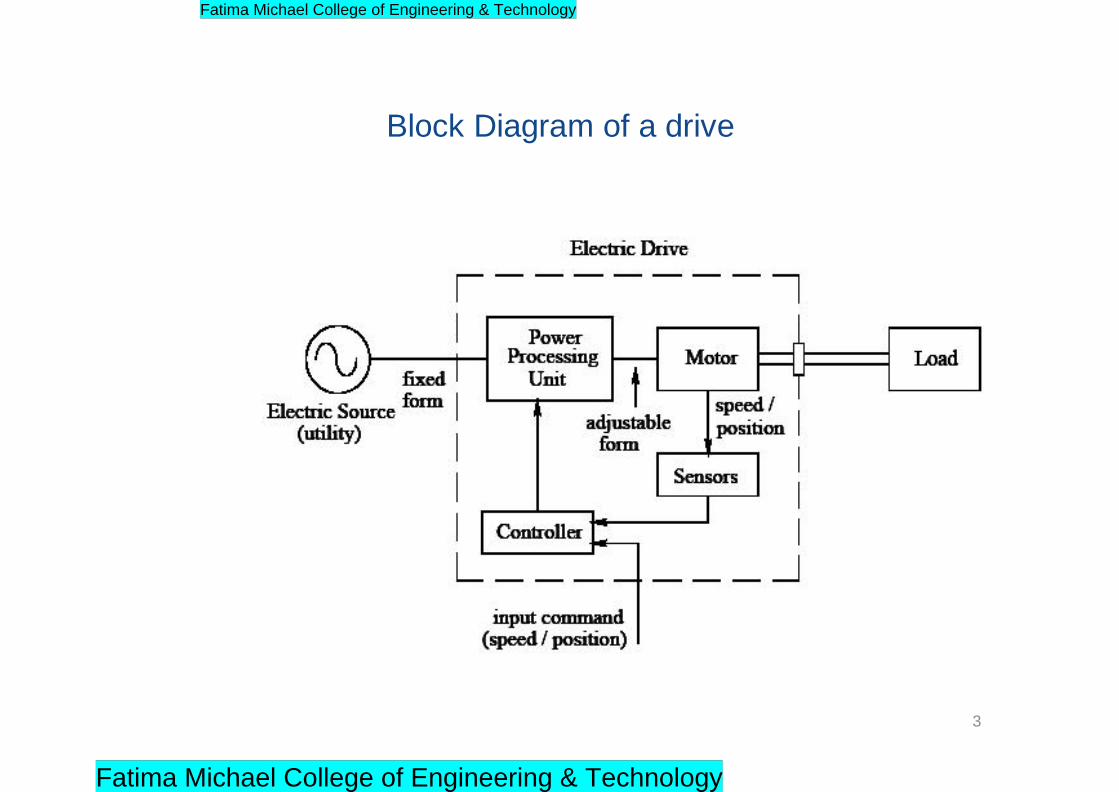
Block Diagram of a drive
3
Fatima Michael College of Engineering & Technology
Fatima Michael College of Engineering & Technology
Type of loads
• Active load torque: - Active torques continues to act in
the same direction irrespective of the direction of the
drive. e.g. gravitational force or deformation in elastic
bodies.
• Passive load torque :- the sense of the load torque
changes with the change in the direction of motion of
drive. e. g. torques due to friction, due to shear and
deformation of inelastic bodies
4
Fatima Michael College of Engineering & Technology
Fatima Michael College of Engineering & Technology
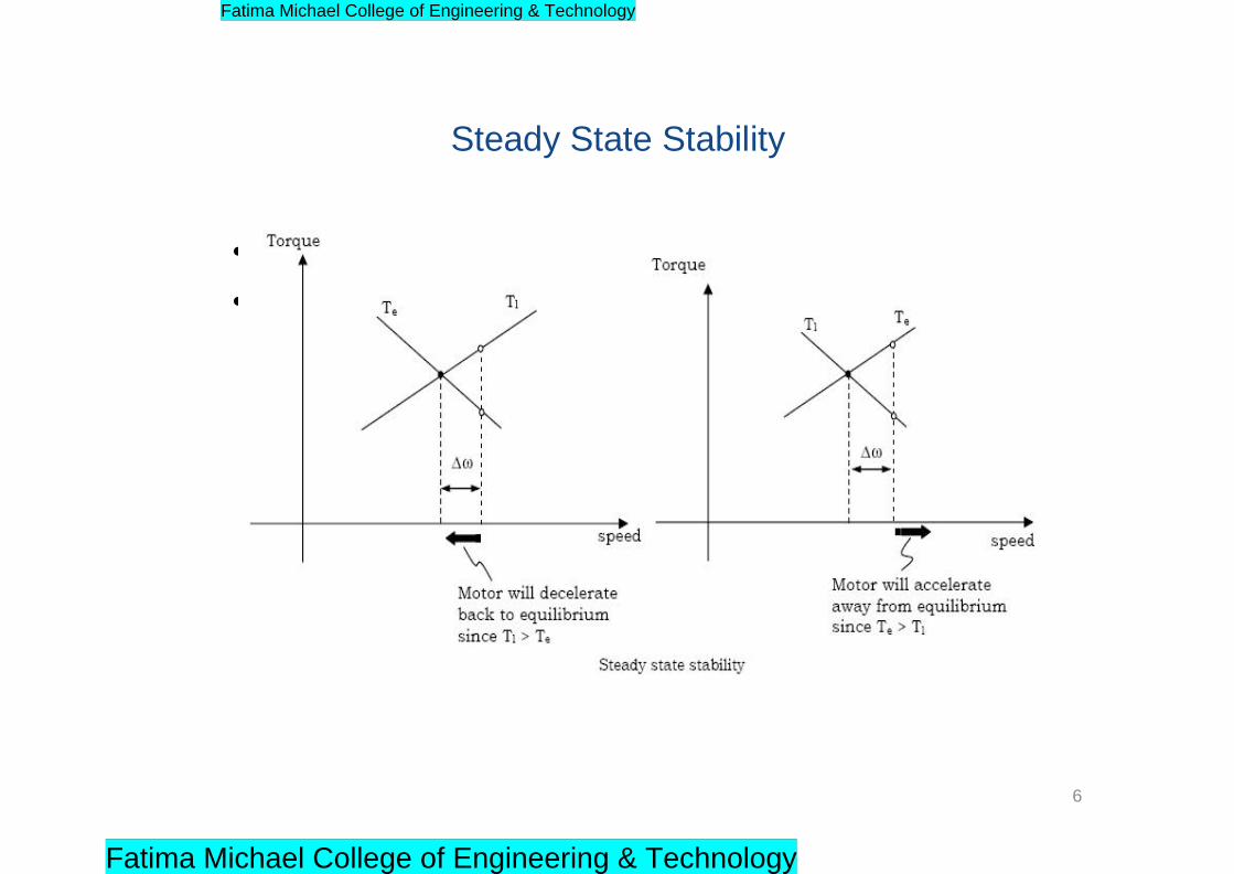
Steady State Stability
• Equilibrium speed of a motor load system is obtained when the
motor torque, Te equals the load torque T l.
Stable state of equilibrium point
– The equilibrium point is termed as stable, if the operating point is
restored after a small departure from it due to disturbance in the
motor or load.
Unstable state of equilibrium point
– The equilibrium point is termed as stable, if the operating point
will not be restored after a small departure from it due to
disturbance in the motor or load.
5
Fatima Michael College of Engineering & Technology
Fatima Michael College of Engineering & Technology
• Possible with variable frequency converter.
• Variable frequency synchronous motor can be
controlled to posses the characteristics of a
separately excited dc motor.
Steady State Stability
6
Fatima Michael College of Engineering & Technology
Fatima Michael College of Engineering & Technology
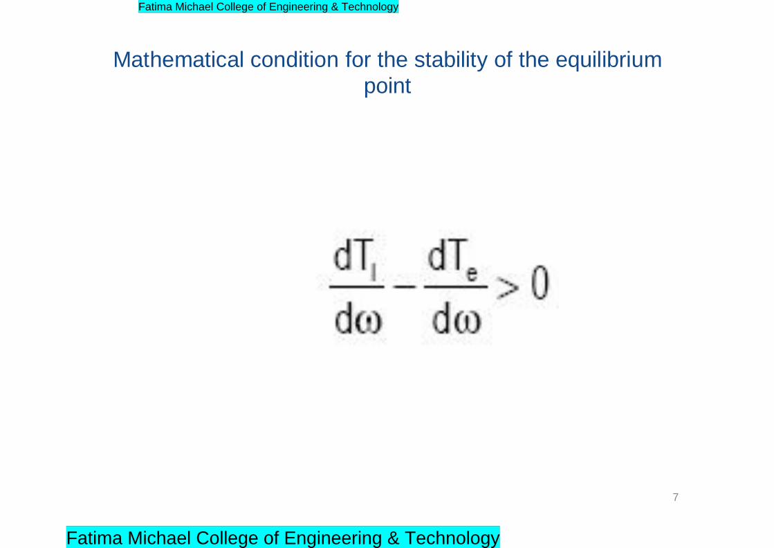
Mathematical condition for the stability of the equilibrium
point
7
Fatima Michael College of Engineering & Technology
Fatima Michael College of Engineering & Technology

Four quadrant operation of a drive
8
Fatima Michael College of Engineering & Technology
Fatima Michael College of Engineering & Technology
Four quadrant operation of a drive
I quadrant
II quadrant
III quadrant
IV quadrant
Operation of
the Hoist
The hoisting
up of the
loaded cage
The hoisting
up of the
unloaded
cage
The
downward
motion of the
unloaded
cage
The
downward
motion of the
loaded cage
Te
+VE
-VE
-VE
+VE
TL
-VE
+VE
+VE
-VE
WM
+VE
+VE
-VE
-VE
Power
+VE
-VE
+VE
-VE
Operation of
the Drive
forward
motoring
Forward
Braking
Reverse
motoring
Reverse
Braking
9
Fatima Michael College of Engineering & Technology
Fatima Michael College of Engineering & Technology
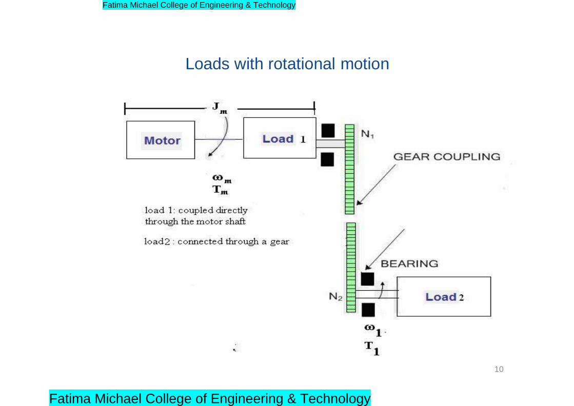
Loads with rotational motion
10
Fatima Michael College of Engineering & Technology
Fatima Michael College of Engineering & Technology
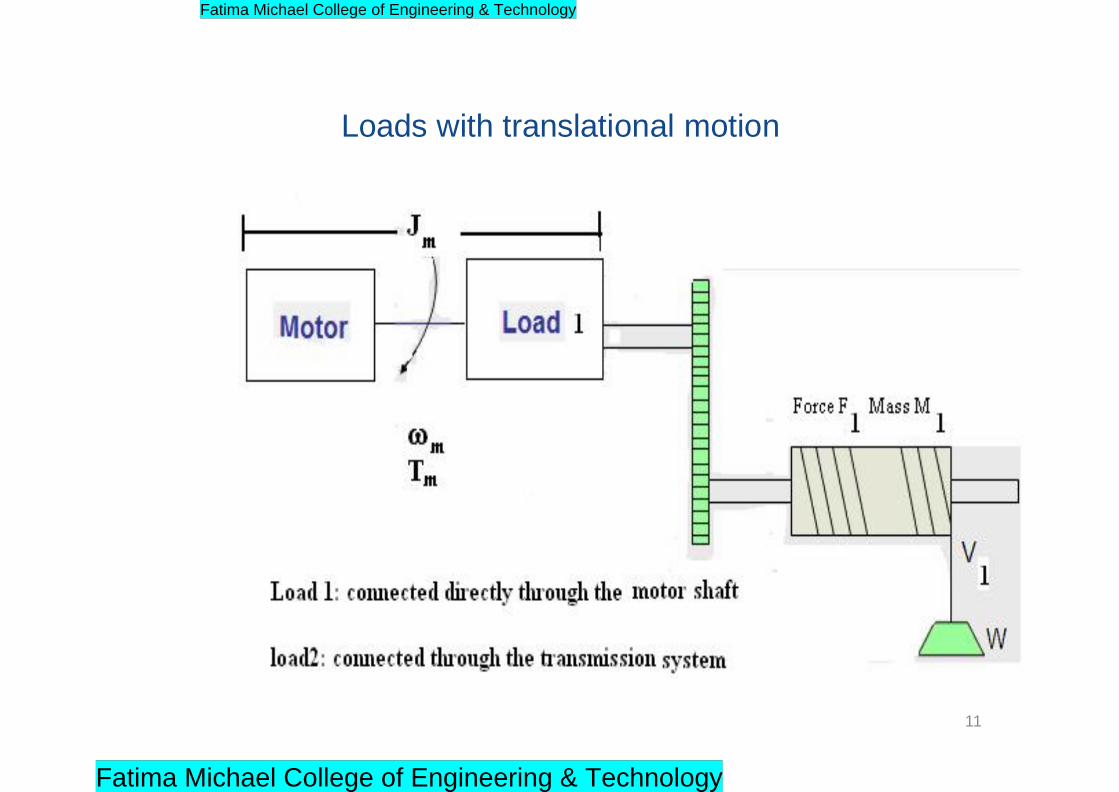
Loads with translational motion
11
Fatima Michael College of Engineering & Technology
Fatima Michael College of Engineering & Technology
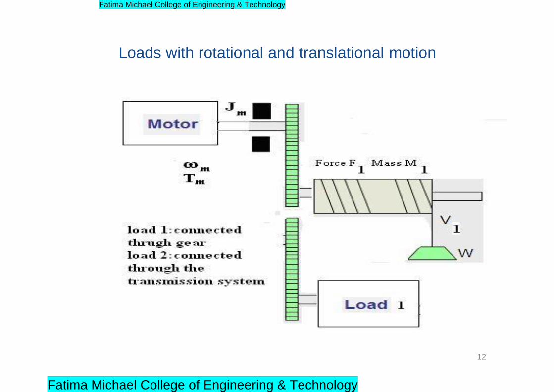
Loads with rotational and translational motion
12
Fatima Michael College of Engineering & Technology
Fatima Michael College of Engineering & Technology
Regenerative Braking
• Working the motor in the generator mode
while it is still connected to the supply and
mechanical energy is converted to electrical
energy and fed back to the supply and
hence the name regenerative braking.
13
Fatima Michael College of Engineering & Technology
Fatima Michael College of Engineering & Technology

Regenerative braking in induction motor
14
Fatima Michael College of Engineering & Technology
Fatima Michael College of Engineering & Technology
References
G.K. Dubey, „Power semi-conductor controlled drives‟, prentice
hall of india,1989.
15
Fatima Michael College of Engineering & Technology
Fatima Michael College of Engineering & Technology

UNIT-II
CONVERTER / CHOPPER FED DC MOTOR
1
Fatima Michael College of Engineering & Technology
Fatima Michael College of Engineering & Technology
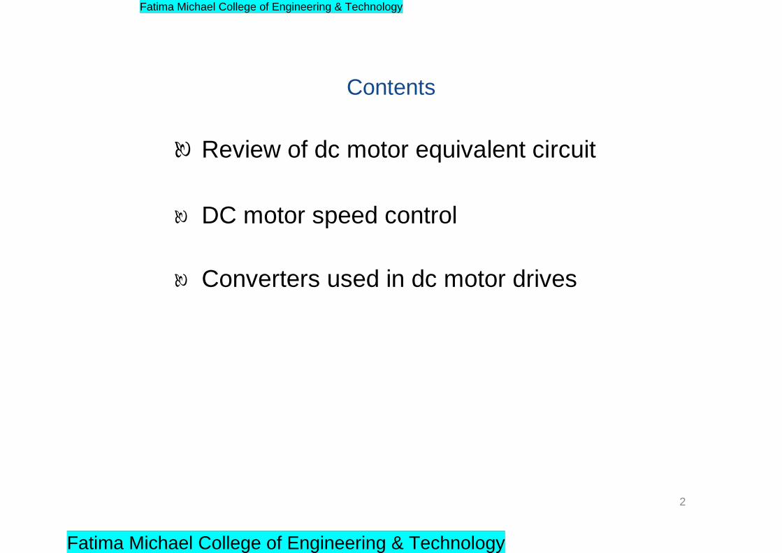
Contents
Review of dc motor equivalent circuit
DC motor speed control
Converters used in dc motor drives
2
Fatima Michael College of Engineering & Technology
Fatima Michael College of Engineering & Technology
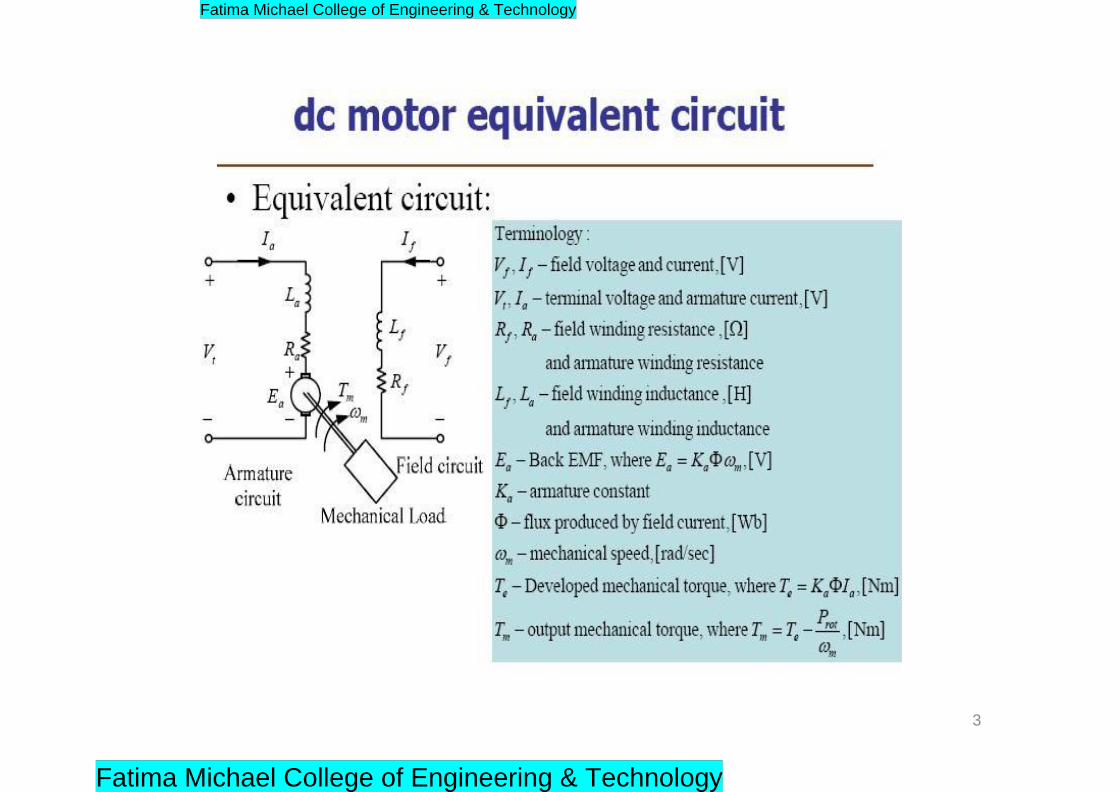
3
Fatima Michael College of Engineering & Technology
Fatima Michael College of Engineering & Technology
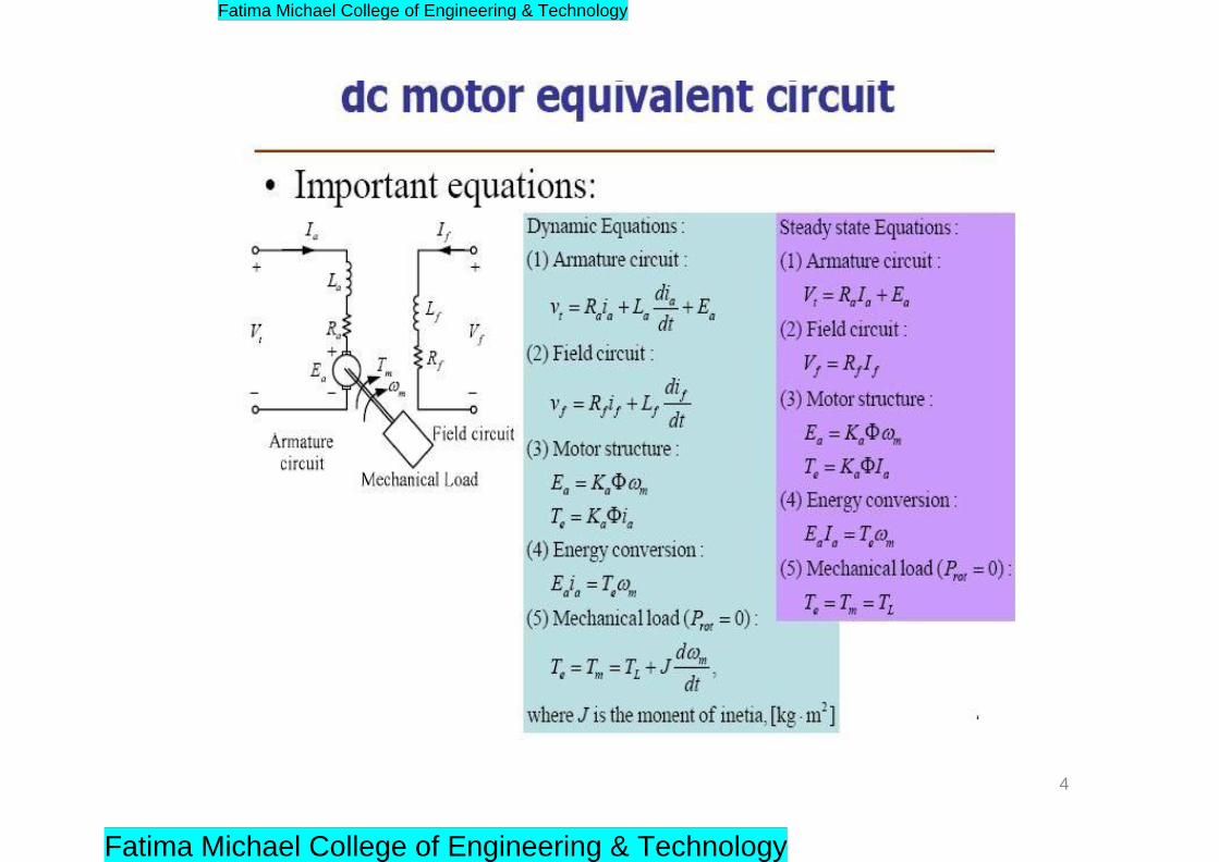
4
Fatima Michael College of Engineering & Technology
Fatima Michael College of Engineering & Technology
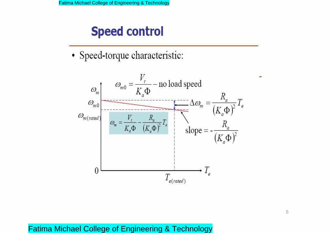
5
Fatima Michael College of Engineering & Technology
Fatima Michael College of Engineering & Technology
SCR “phase-angle controlled” DC drives
• By changing the firing angle, variable DC output voltage can
be obtained.
• Single phase (low power) and three phase (high and very
high power) supply can be used
• The line current is unidirectional, but the output voltage can
reverse polarity. Hence 2- quadrant operation is inherently
possible.
• 4-quadrant is also possible using “two sets” of controlled
rectifiers.
6
Fatima Michael College of Engineering & Technology
Fatima Michael College of Engineering & Technology
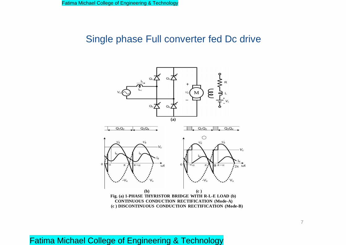
Single phase Full converter fed Dc drive
(a)
(b) (c )
Fig. (a) 1-PHASE THYRISTOR BRIDGE WITH R-L-E LOAD (b)
CONTINUOUS CONDUCTION RECTIFICATION (Mode-A)
(c ) DISCONTINUOUS CONDUCTION RECTIFICATION (Mode-B)
7
Fatima Michael College of Engineering & Technology
Fatima Michael College of Engineering & Technology

(a)
(b)
Fig. (a) CONTINUOUS CONDUCTION INVERSION MODE (Mode-C)
(b) DISCONTINUOUS CONDUCTION INVERSION MODE (Mode-D)
8
Fatima Michael College of Engineering & Technology
Fatima Michael College of Engineering & Technology
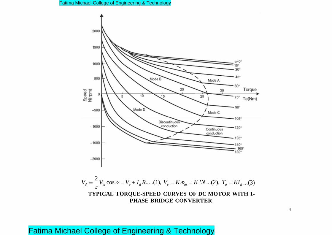
V 2
V
cos V
I R.....(1), V
K
K 'N ...(2), T
KI
...(3)d
m c d c m e d
TYPICAL TORQUE-SPEED CURVES OF DC MOTOR WITH 1-
PHASE BRIDGE CONVERTER
9
Fatima Michael College of Engineering & Technology
Fatima Michael College of Engineering & Technology
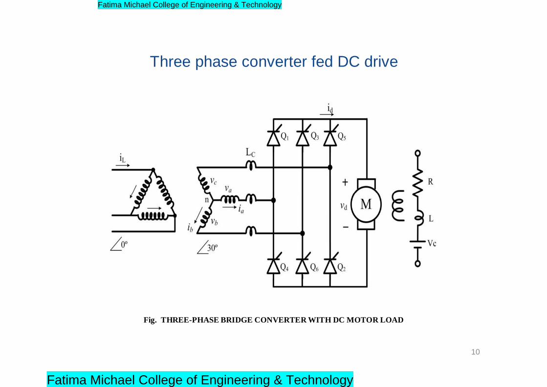
Three phase converter fed DC drive
Fig. THREE-PHASE BRIDGE CONVERTER WITH DC MOTOR LOAD
10
Fatima Michael College of Engineering & Technology
Fatima Michael College of Engineering & Technology
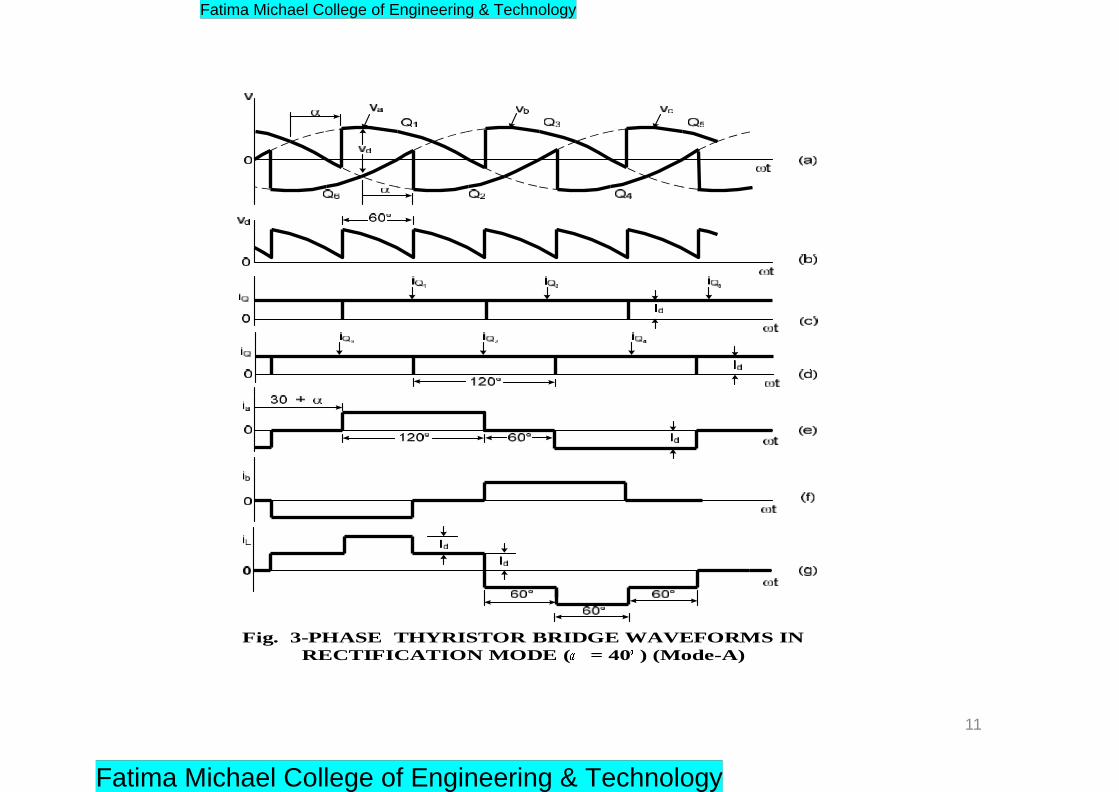
Fig. 3-PHASE THYRISTOR BRIDGE WAVEFORMS IN
RECTIFICATION MODE ( = 40 ) (Mode-A)
11
Fatima Michael College of Engineering & Technology
Fatima Michael College of Engineering & Technology
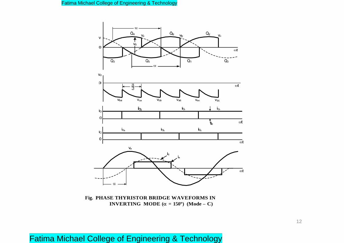
Fig. PHASE THYRISTOR BRIDGE WAVEFORMS IN
INVERTING MODE ( = 150 ) (Mode – C)
12
Fatima Michael College of Engineering & Technology
Fatima Michael College of Engineering & Technology
1 2
V
V a b
V a c
V b c
V b a
V c a
d
(a ) V
c
0
i d
Q 1
Q 6 Q Q
t
0
/ 3
Q 1
Q 6
Q 1
Q 2
i d
t 2
(b )
V
c
v
b c v
b a v c a
v c b
v a b
v a c
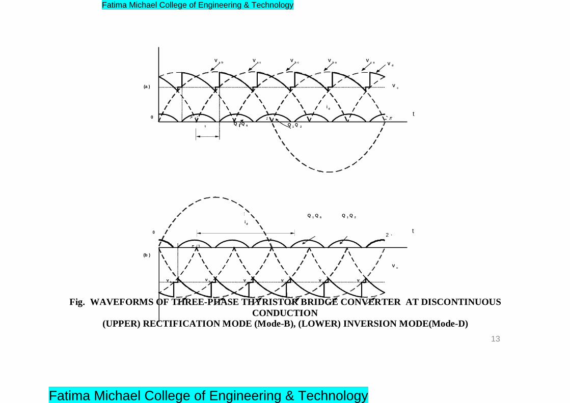
Fig. WAVEFORMS OF THREE-PHASE THYRISTOR BRIDGE CONVERTER AT DISCONTINUOUS
CONDUCTION (UPPER) RECTIFICATION MODE (Mode-B), (LOWER) INVERSION MODE(Mode-D)
13
Fatima Michael College of Engineering & Technology
Fatima Michael College of Engineering & Technology
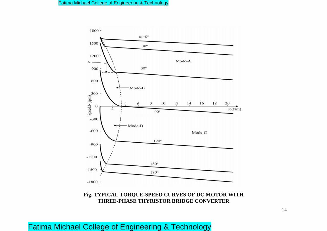
Fig. TYPICAL TORQUE-SPEED CURVES OF DC MOTOR WITH
THREE-PHASE THYRISTOR BRIDGE CONVERTER
14
Fatima Michael College of Engineering & Technology
Fatima Michael College of Engineering & Technology
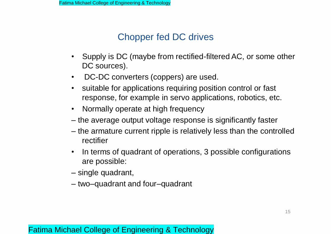
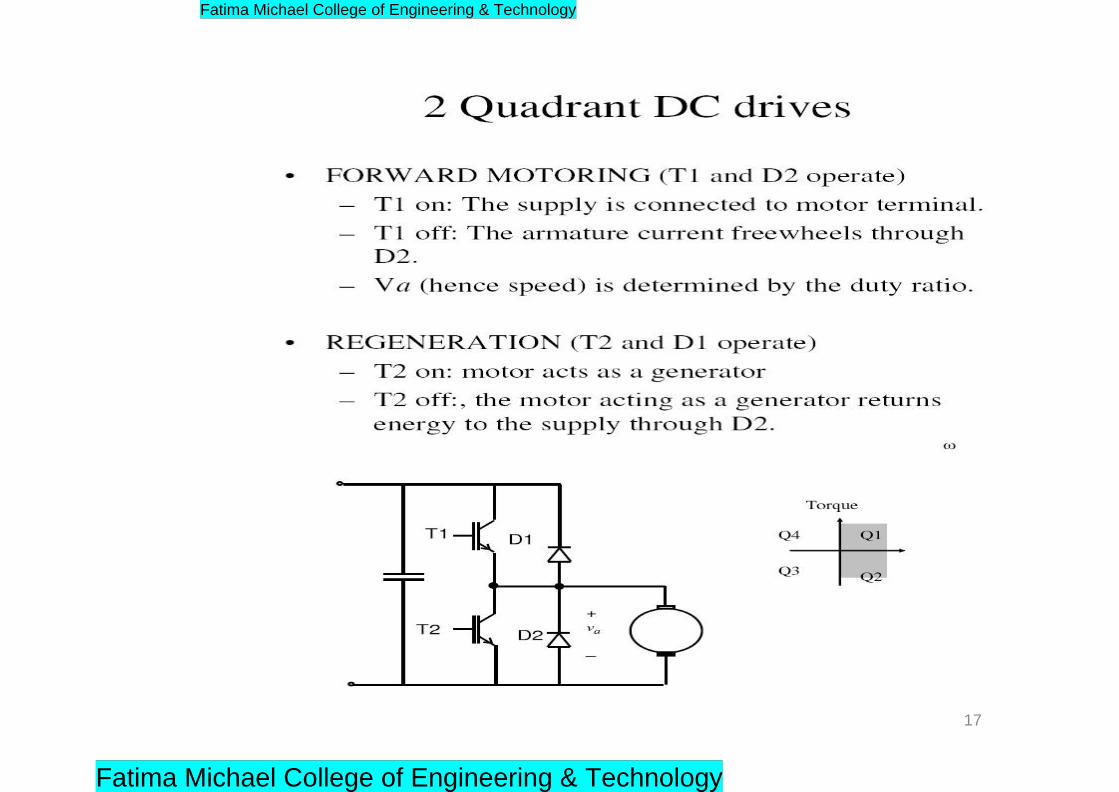
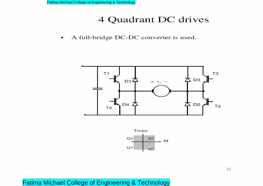
Chopper fed DC drives
• Supply is DC (maybe from rectified-filtered AC, or some other
DC sources).
• DC-DC converters (coppers) are used.
• suitable for applications requiring position control or fast
response, for example in servo applications, robotics, etc.
• Normally operate at high frequency
– the average output voltage response is significantly faster
– the armature current ripple is relatively less than the controlled
rectifier
• In terms of quadrant of operations, 3 possible configurations
are possible:
– single quadrant,
– two–quadrant and four–quadrant
15
Fatima Michael College of Engineering & Technology
Fatima Michael College of Engineering & Technology

16
Fatima Michael College of Engineering & Technology
Fatima Michael College of Engineering & Technology
17
Fatima Michael College of Engineering & Technology
Fatima Michael College of Engineering & Technology
18
Fatima Michael College of Engineering & Technology
Fatima Michael College of Engineering & Technology
References
G.K. Dubey, „Power semi-conductor controlled drives‟, prentice hall of
india,1989.
19
Fatima Michael College of Engineering & Technology
Fatima Michael College of Engineering & Technology
Unit -III DESIGN OF CONTROLLERS FOR DRIVES
1
Fatima Michael College of Engineering & Technology
Fatima Michael College of Engineering & Technology
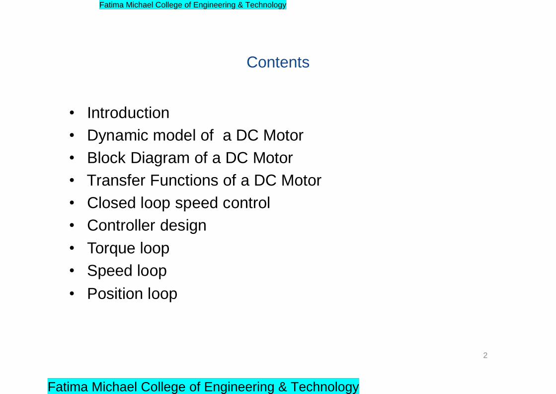
Contents
• Introduction
• Dynamic model of a DC Motor
• Block Diagram of a DC Motor
• Transfer Functions of a DC Motor
• Closed loop speed control
• Controller design
• Torque loop
• Speed loop
• Position loop
2
Fatima Michael College of Engineering & Technology
Fatima Michael College of Engineering & Technology
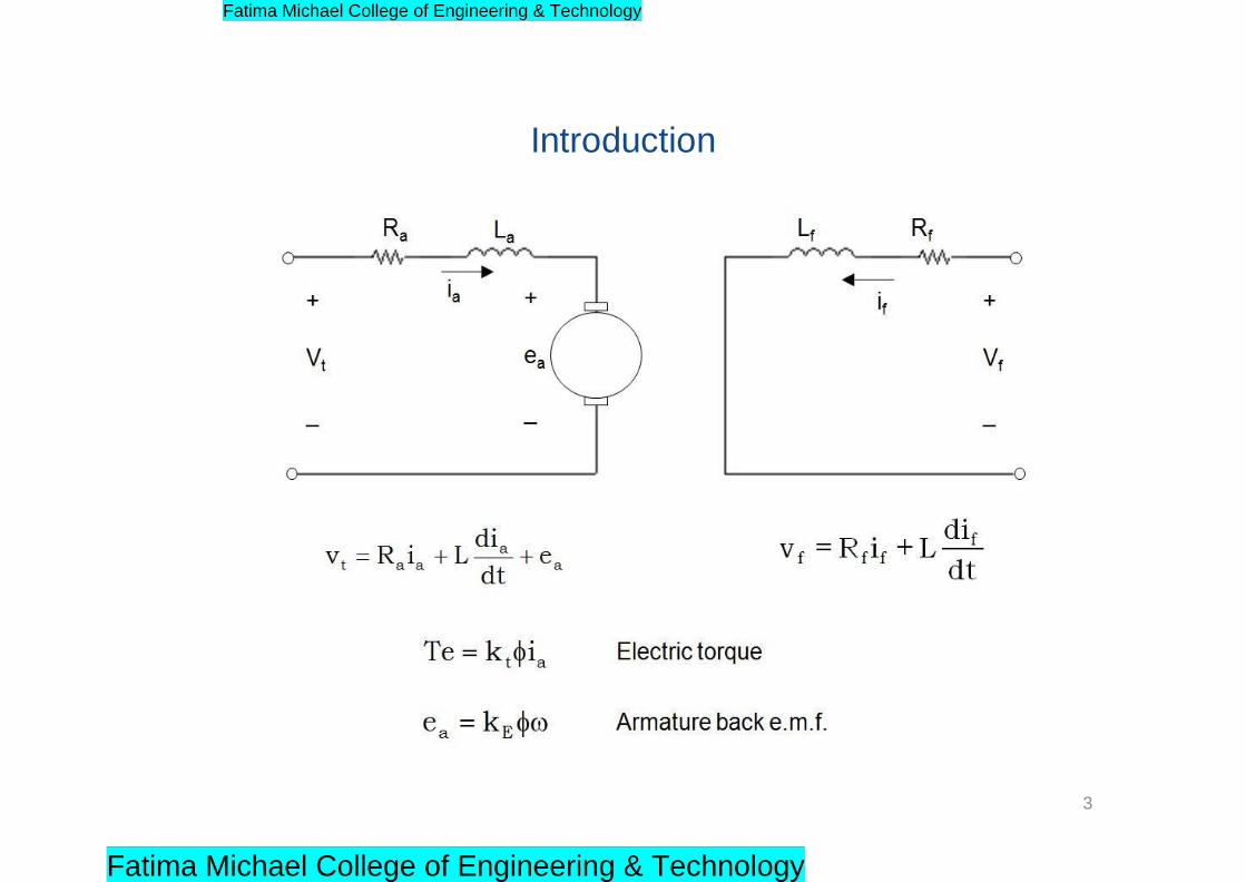
Introduction
3
Fatima Michael College of Engineering & Technology
Fatima Michael College of Engineering & Technology

Introduction
4
Fatima Michael College of Engineering & Technology
Fatima Michael College of Engineering & Technology
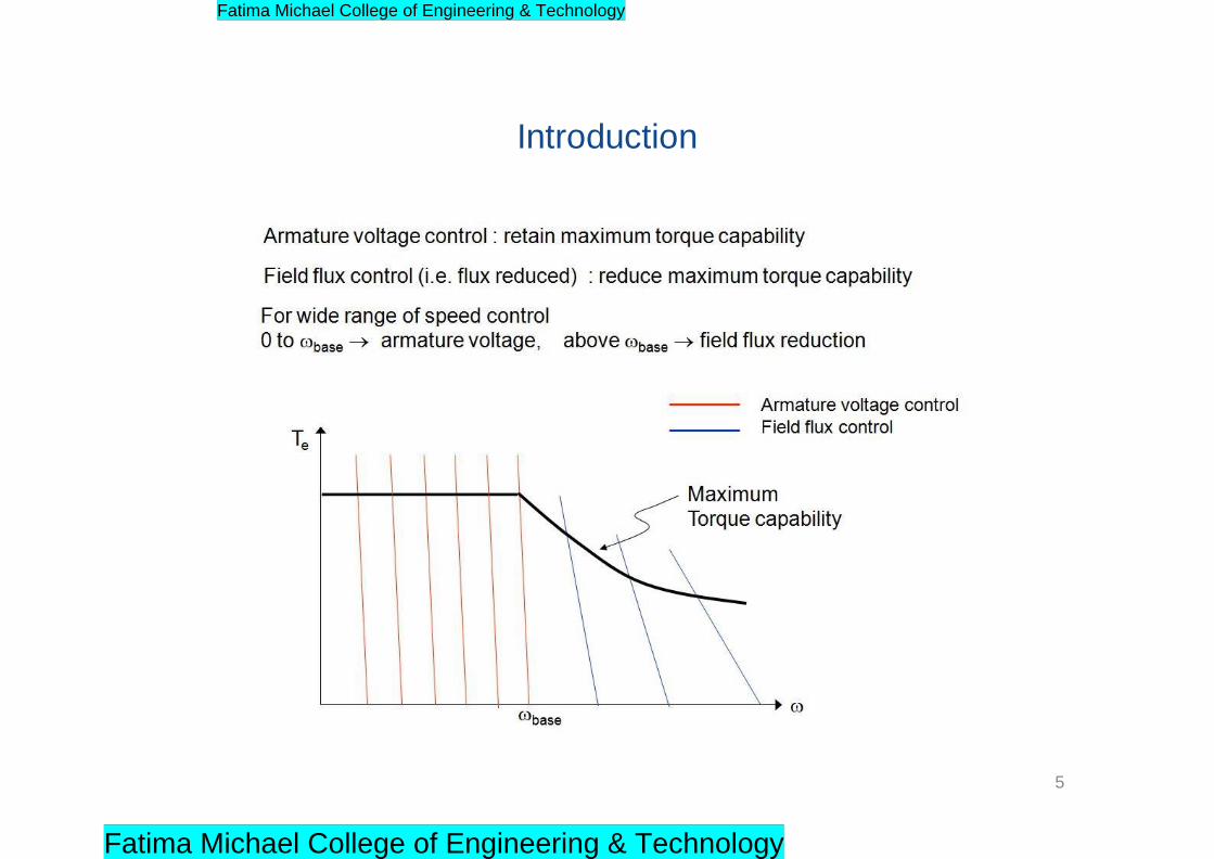
Introduction
5
Fatima Michael College of Engineering & Technology
Fatima Michael College of Engineering & Technology
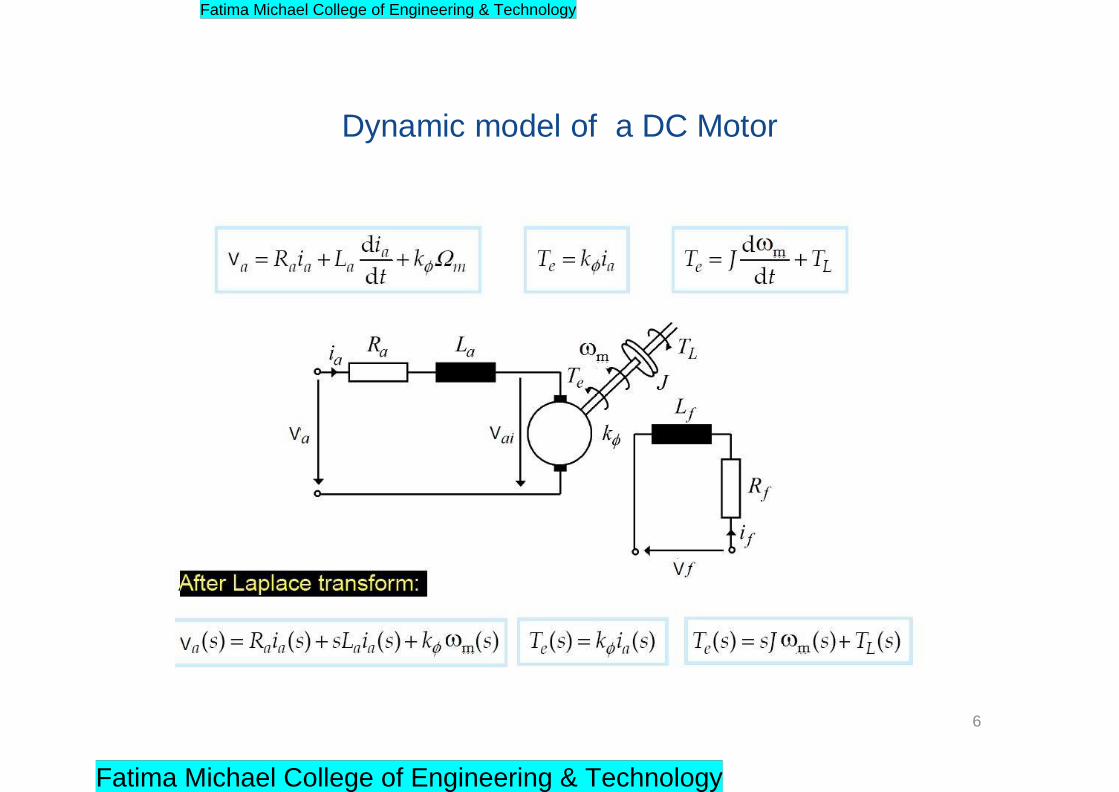
Dynamic model of a DC Motor
6
Fatima Michael College of Engineering & Technology
Fatima Michael College of Engineering & Technology
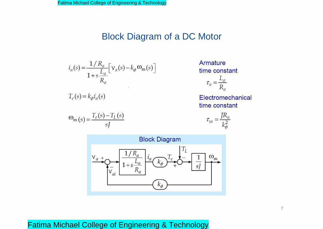
Block Diagram of a DC Motor
7
Fatima Michael College of Engineering & Technology
Fatima Michael College of Engineering & Technology
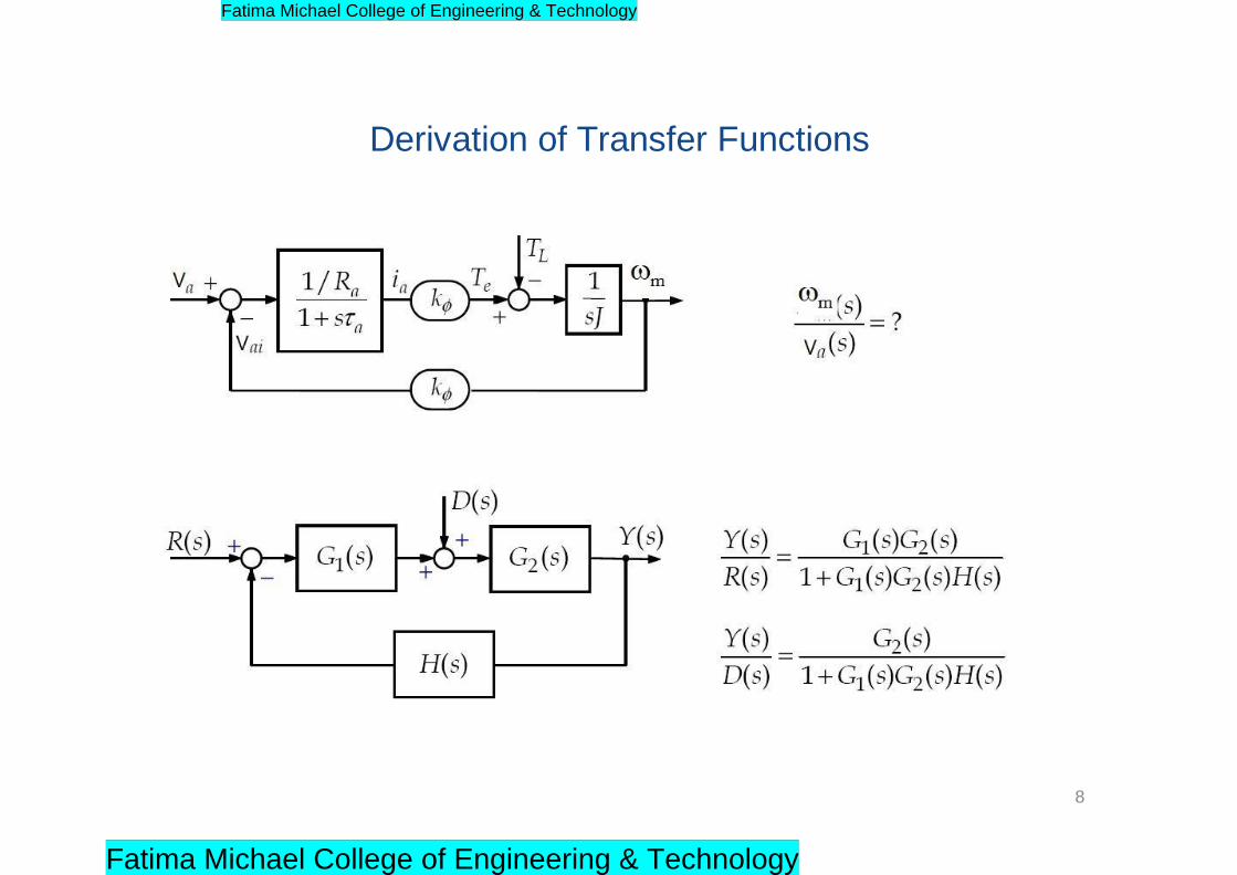
Derivation of Transfer Functions
8
Fatima Michael College of Engineering & Technology
Fatima Michael College of Engineering & Technology
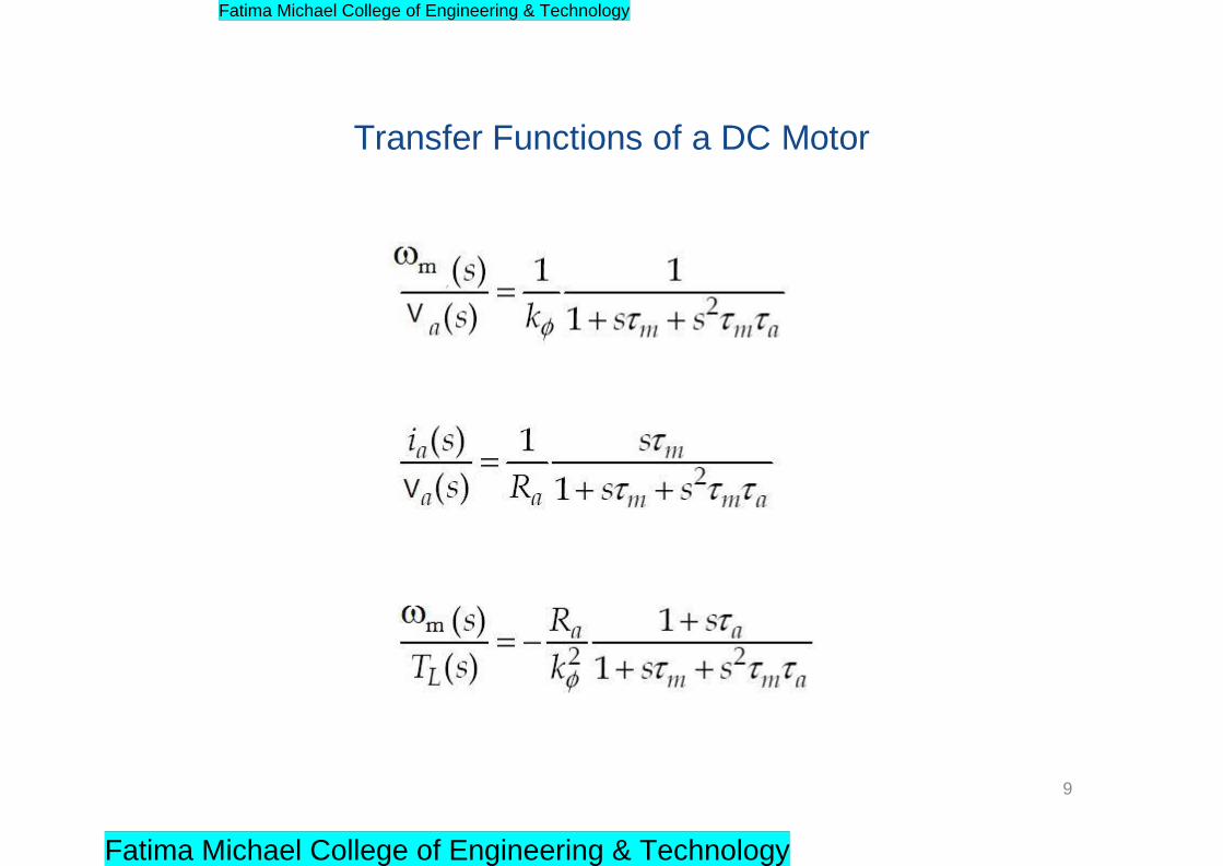
Transfer Functions of a DC Motor
9
Fatima Michael College of Engineering & Technology
Fatima Michael College of Engineering & Technology
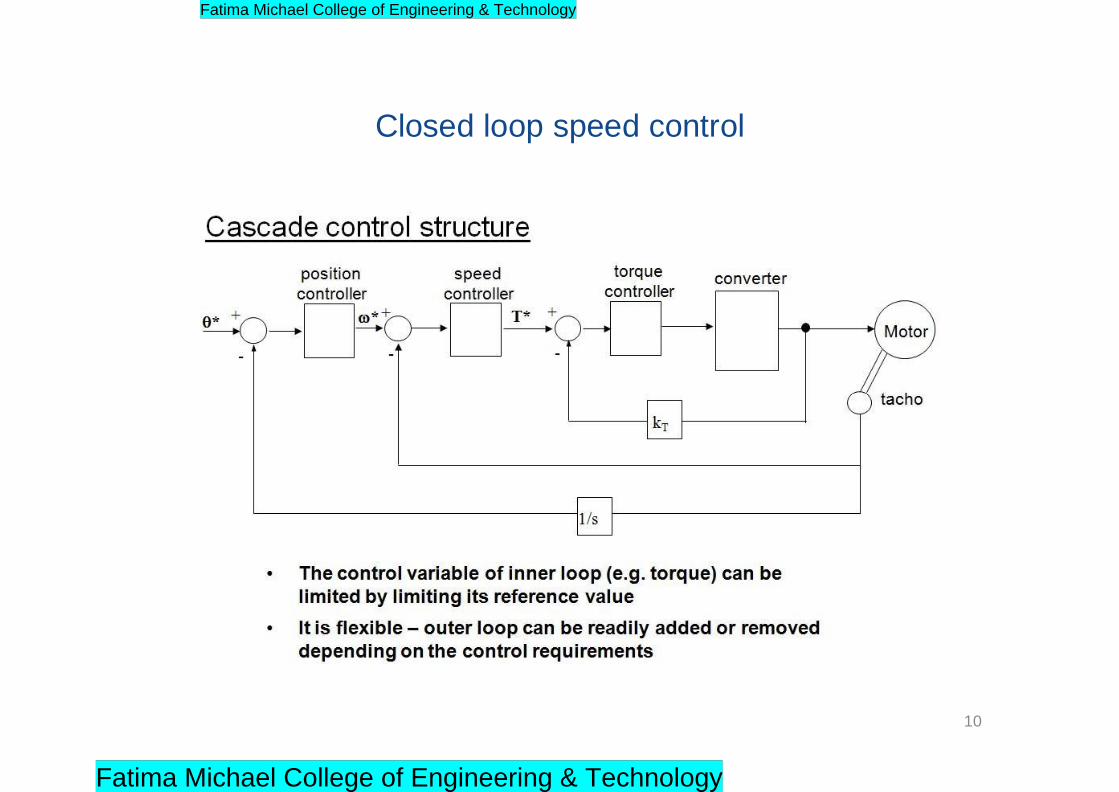
Closed loop speed control
10
Fatima Michael College of Engineering & Technology
Fatima Michael College of Engineering & Technology
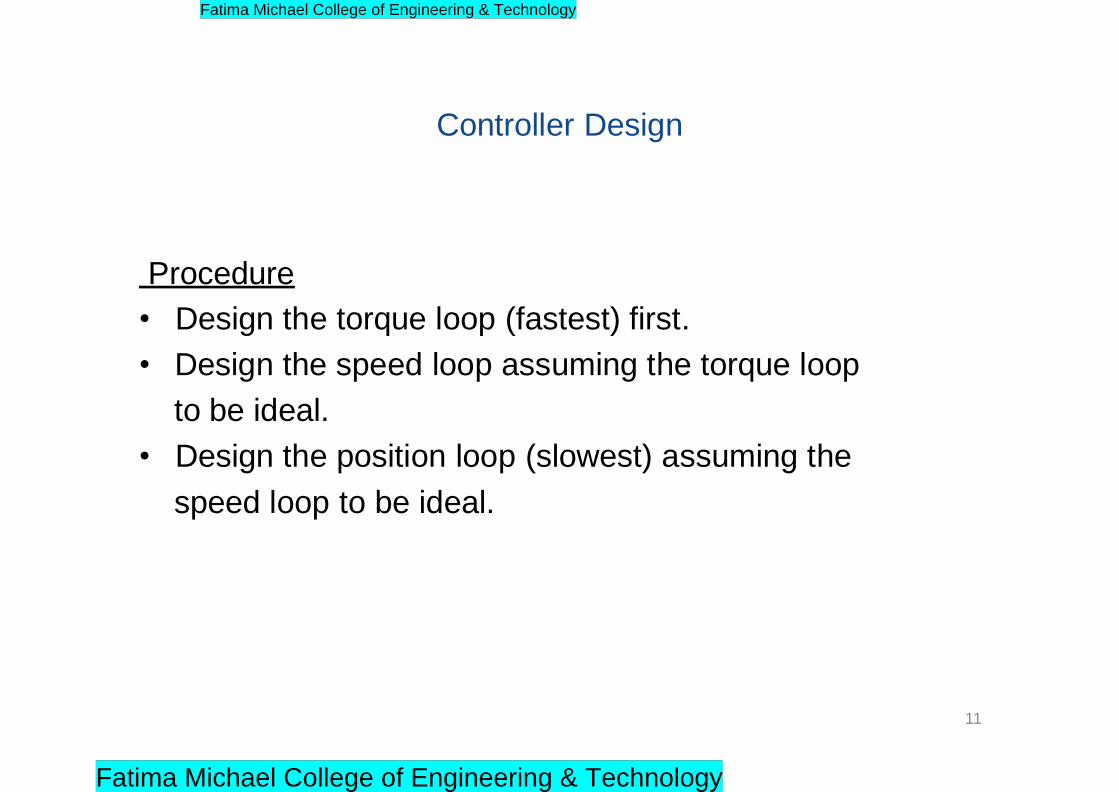
Controller Design
Procedure
• Design the torque loop (fastest) first.
• Design the speed loop assuming the torque loop
to be ideal.
• Design the position loop (slowest) assuming the
speed loop to be ideal.
11
Fatima Michael College of Engineering & Technology
Fatima Michael College of Engineering & Technology
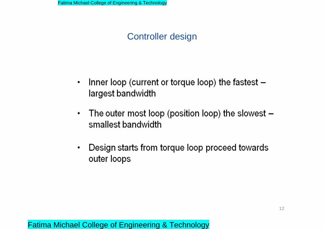
Controller design
12
Fatima Michael College of Engineering & Technology
Fatima Michael College of Engineering & Technology
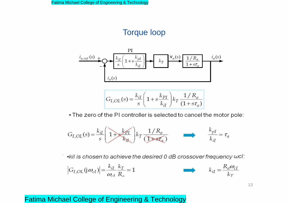
Torque loop
13
Fatima Michael College of Engineering & Technology
Fatima Michael College of Engineering & Technology

Speed loop
14
Fatima Michael College of Engineering & Technology
Fatima Michael College of Engineering & Technology
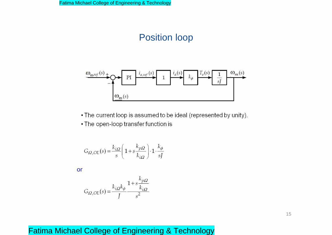
Position loop
15
Fatima Michael College of Engineering & Technology
Fatima Michael College of Engineering & Technology

References
• G.K. Dubey, „Power semi-conductor controlled drives‟, prentice hall of india, 1989.
16
Fatima Michael College of Engineering & Technology
Fatima Michael College of Engineering & Technology
Unit -IV
INDUCTION MOTOR DRIVES
1
Fatima Michael College of Engineering & Technology
Fatima Michael College of Engineering & Technology

Contents
Advantageous features of converter Fed induction motor in comparison with line fed induction motor
Speed control of induction
Speed control by Variable Voltage method
speed control by rotor resistance variation
Slip Energy Recovery Schemes
Speed Control of IM Using Variable Frequency
Features of VSI Fed IM Drives
Features of PWM Fed IM Drives
Features of CSI Fed IM Drives
Slip controlled Drives
2
Fatima Michael College of Engineering & Technology
Fatima Michael College of Engineering & Technology
Advantageous features of converter Fed induction motor in
comparison with line fed induction motor
Smooth Speed variation with VVVF(Variable Voltage Variable Frequency)
Assured smooth Start up
Soft Starting and acceleration at constant current and torque are possible.
No switching surge currents with Direct Switching on even for Higher Ratings
High Moments of Inertia can be accelerated without the need for over dimensioning the motor
Speed control of IM by changing slip frequency.
Speed control of IM by changing stator frequency which can change the Synchronous speed of the motor
3
Fatima Michael College of Engineering & Technology
Fatima Michael College of Engineering & Technology
Speed control of induction motor
Three simple means of limited speed control for an
induction motor are:
1) Reduced applied voltage magnitude
2) Adjusting rotor circuit resistance
(suitable for a wound rotor machine
and discussed earlier)
3) Adjusting stator voltage and frequency
4
Fatima Michael College of Engineering & Technology
Fatima Michael College of Engineering & Technology
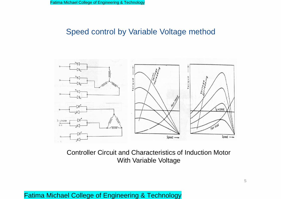
Speed control by Variable Voltage method
Controller Circuit and Characteristics of Induction Motor
With Variable Voltage
5
Fatima Michael College of Engineering & Technology
Fatima Michael College of Engineering & Technology
2
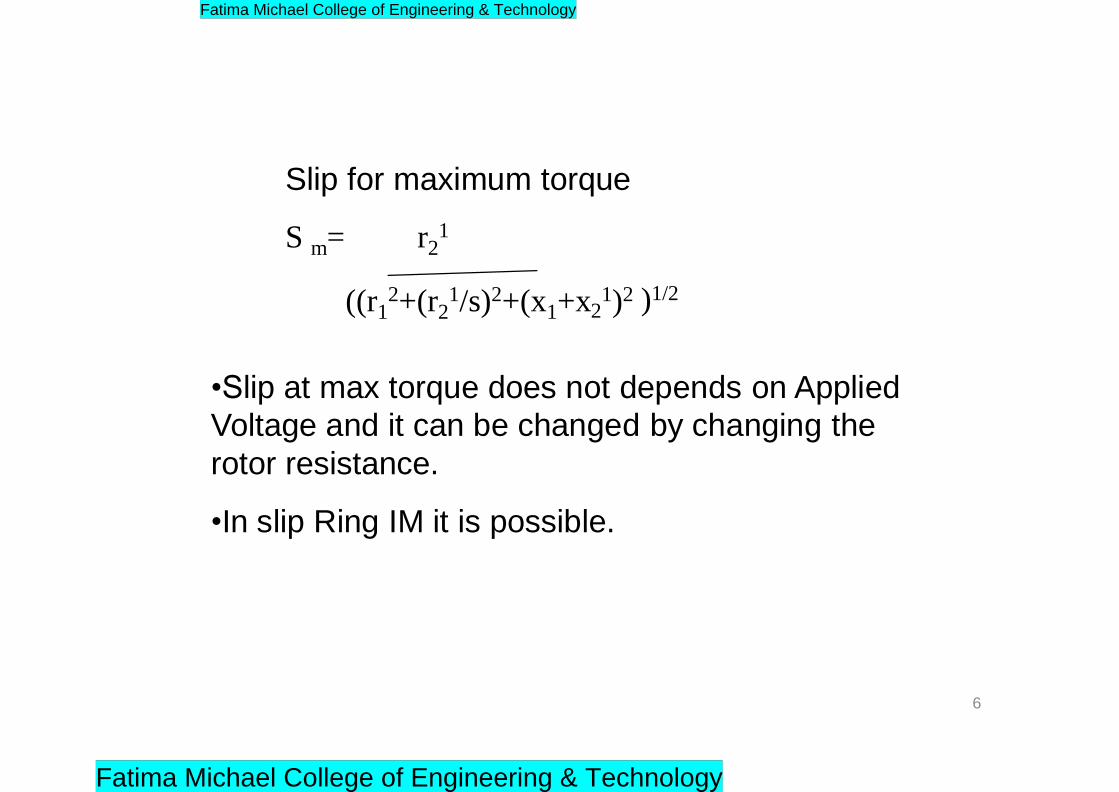
Slip for maximum torque
S m= r21
((r12+(r2
1/s)2+(x1+x 1)2 )1/2
•Slip at max torque does not depends on Applied
Voltage and it can be changed by changing the
rotor resistance.
•In slip Ring IM it is possible.
6
Fatima Michael College of Engineering & Technology
Fatima Michael College of Engineering & Technology
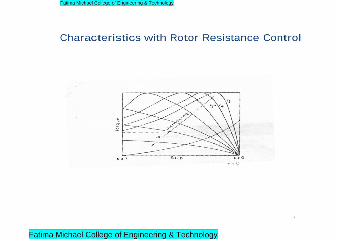
Characteristics with Rotor Resistance Control
7
Fatima Michael College of Engineering & Technology
Fatima Michael College of Engineering & Technology
r
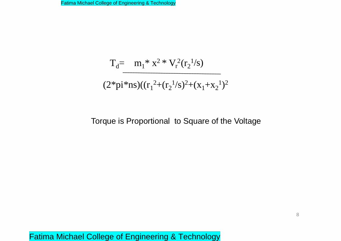
Td= m1* x2 * V 2 (r21 /s)
(2*pi*ns)((r12+(r2
1/s)2+(x1+x21)2
Torque is Proportional to Square of the Voltage
8
Fatima Michael College of Engineering & Technology
Fatima Michael College of Engineering & Technology
Conclusion from the above characteristics
• Linear portion of torque curve meets the locus of the
breakdown torque point.
• Sm increases with increase in r21
• Maximum torque is independent of r21
• If Slip increases rotor copper loss increases
9
Fatima Michael College of Engineering & Technology
Fatima Michael College of Engineering & Technology
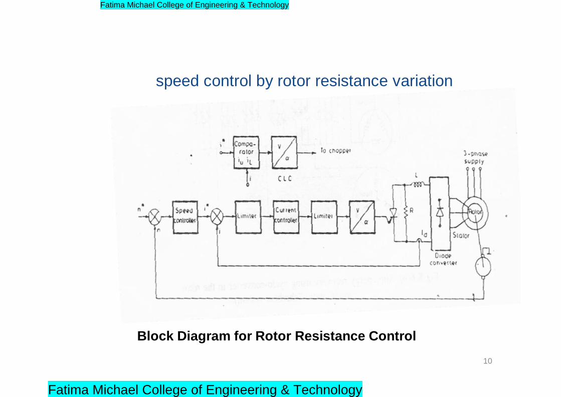
speed control by rotor resistance variation
Block Diagram for Rotor Resistance Control
10
Fatima Michael College of Engineering & Technology
Fatima Michael College of Engineering & Technology
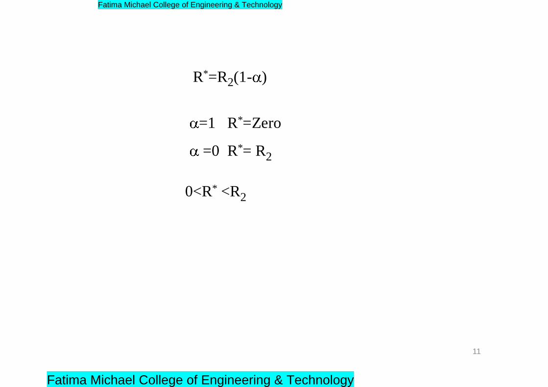
R*=R2(1- )
=1 R*=Zero
=0 R*= R2
0<R* <R2
11
Fatima Michael College of Engineering & Technology
Fatima Michael College of Engineering & Technology

Features
• Speed Range
• Braking
• Harmonics
• Torque Pulsations
• Good pf
• Poor Efficiency
• Reasonable Cost
• General
12
Fatima Michael College of Engineering & Technology
Fatima Michael College of Engineering & Technology
Draw backs of Stator Voltage Control and Rotor
Resistance Control
• Poor Efficiency at low speed.
• Limited range of Speed Control
• Slip power is wasted in the Motor
• Resistances in Stator Control and in Rotor
Resistance in Rotor Resistance control
13
Fatima Michael College of Engineering & Technology
Fatima Michael College of Engineering & Technology
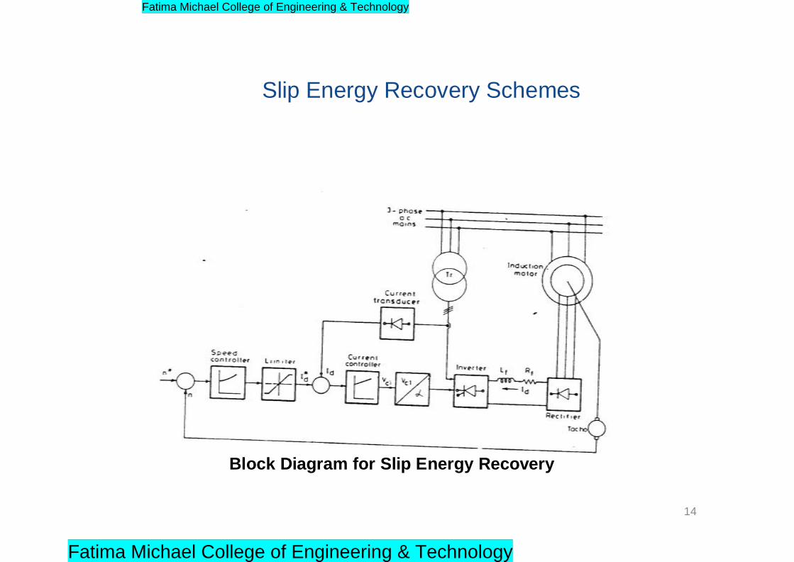
Slip Energy Recovery Schemes
Block Diagram for Slip Energy Recovery
14
Fatima Michael College of Engineering & Technology
Fatima Michael College of Engineering & Technology

Dc voltage of the diode rectifier
Vd=1.35(sE 20)
Corresponding to no voltage condition
Vd0=1.35(sE 20)
For Stator to Rotor turns Ratio „a‟
Vd0=1.35(sVL/a)
15
Fatima Michael College of Engineering & Technology
Fatima Michael College of Engineering & Technology

Vdi= 1.35(VL cos )
Vd0= -Vdi
1.35(VL cos )=1.35(sVL/a)
s= -a cos
Rotor Copper loss =sPg (Pg -Air Gap Power)
16
Fatima Michael College of Engineering & Technology
Fatima Michael College of Engineering & Technology
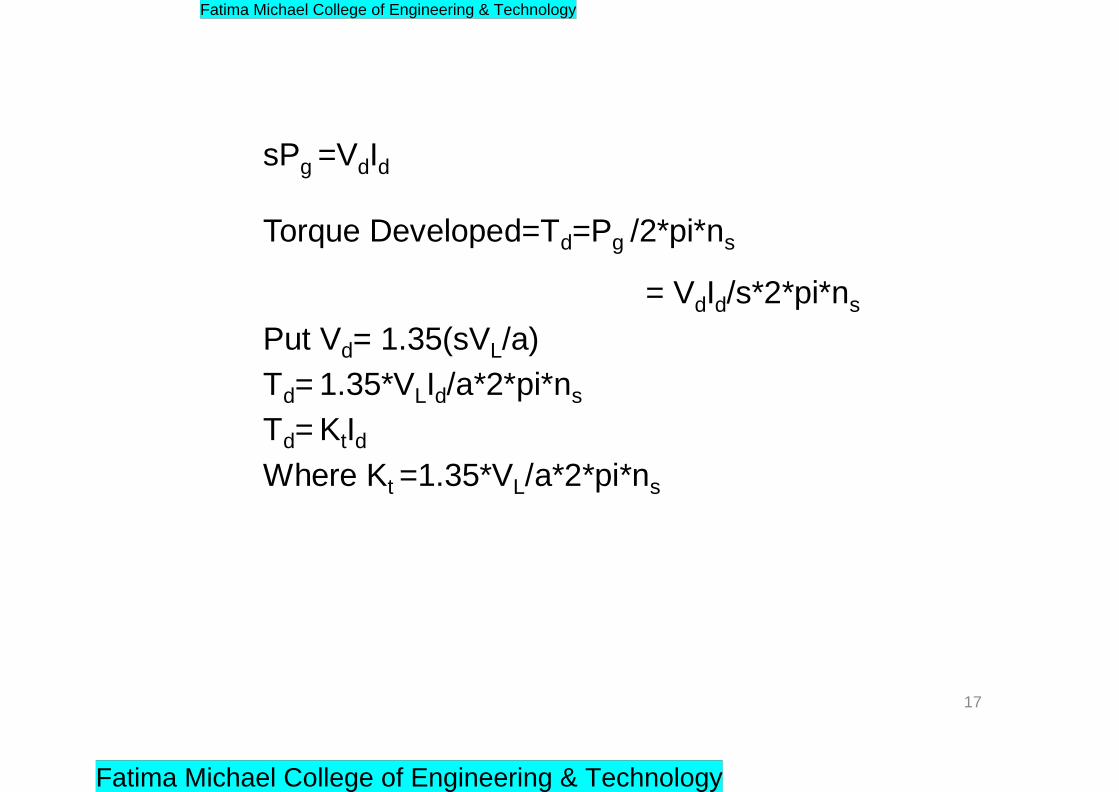
sPg =VdId
Torque Developed=Td=Pg /2*pi*ns
Put Vd= 1.35(sVL/a)
Td= 1.35*VLId/a*2*pi*ns
Td= KtId
= VdId/s*2*pi*ns
Where Kt =1.35*VL/a*2*pi*ns
17
Fatima Michael College of Engineering & Technology
Fatima Michael College of Engineering & Technology
Features of Slip Power Recovery
• Power Factor is Improved
• Slip Power Can be recovered to the mains instead of
wasting the same in the resistances of the motor itself.
• Converter group handles Slip power only. Therefore it‟s
rating can be low if speed control is in a limited range.
Contd..
18
Fatima Michael College of Engineering & Technology
Fatima Michael College of Engineering & Technology
• For achieving Zero Speed Converter rating should
be equal to the Motor rating.
• Improved efficiency
• Maximum power factor attained is 0.7.Still the pf can be improved by designing the inverter if the converter operates at 180 Degree firing angle
Contd..
19
Fatima Michael College of Engineering & Technology
Fatima Michael College of Engineering & Technology
For Achieving Super synchronous Speed ,Power should
flow to the rotor circuit Via the converter Cascade.
This can be achieved by
20
Fatima Michael College of Engineering & Technology
Fatima Michael College of Engineering & Technology
Achievement of Super Synchronous Speed
• Replacing Diode rectifier by Phase Controlled rectifier operating as rectifier.
• By replacing converter cascade by a Cycloconverter.This is known as Scherbius Drives
Rotor Currents are non sinusoidal and it causes network
reactions and torque pulsations.
21
Fatima Michael College of Engineering & Technology
Fatima Michael College of Engineering & Technology

Scherbius systems
Power Circuit Diagram for Scherbius Systems
22
Fatima Michael College of Engineering & Technology
Fatima Michael College of Engineering & Technology
Speed Control of IM Using Variable Frequency
• f= pns
• If frequency varies Saturation Problems Will occur
– To avoid this V/f has to maintained at a
constant value
– To avoid Impedance drop at low frequency compensation is necessary (i.e E/f Control)
23
Fatima Michael College of Engineering & Technology
Fatima Michael College of Engineering & Technology
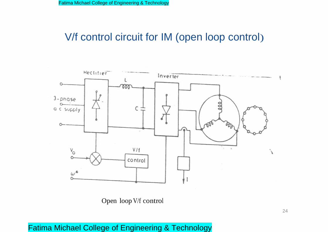
V/f control circuit for IM (open loop control)
Open loop V/f control
24
Fatima Michael College of Engineering & Technology
Fatima Michael College of Engineering & Technology
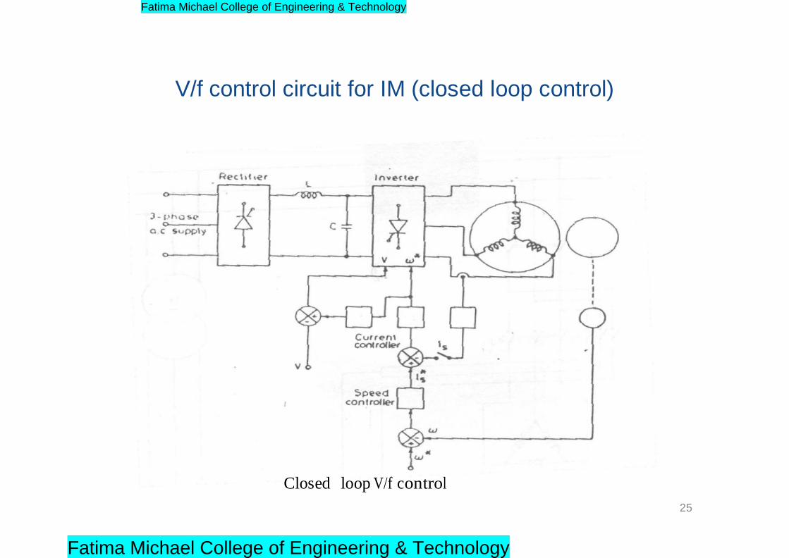
V/f control circuit for IM (closed loop control)
Closed loop V/f control
25
Fatima Michael College of Engineering & Technology
Fatima Michael College of Engineering & Technology

Features of v/f control
• Best possible utilisation of available current capability
• Generate Highest possible Torque per Ampere of Stator
Current.
26
Fatima Michael College of Engineering & Technology
Fatima Michael College of Engineering & Technology
Can be used for Multi motor Drives Load independent Commutation of the Inverter
Inverter Frequencies can go up to 1500 Hz.
Suitable for high speed operation
Capacity upto 100 KVA
At very low speed Commutation voltage is also very low. Up to 10% of the Speed is not realisable.
Speed Range 1:20
Not suitable for acceleration on Load and Sudden Load Changes
Dynamic braking can be realised by an additional converter at the line side.
Low cost with simple control circuit.
Efficiency is very poor.
27
Contd..
Features of VSI Fed IM Drives
Devices.
Fatima Michael College of Engineering & Technology
Fatima Michael College of Engineering & Technology
Features of PWM Based VSI Fed IM Drives
• Speed range: Up to zero speed
• Nearly Sinusoidal voltage and current.
• Minimized torque pulsations.
• Line pf is closer to Unity.
• High converter cost.
• Inverter has constant dc link voltage and employs PWM principle for both voltage control and Harmonic neutralisation.
28
Fatima Michael College of Engineering & Technology
Fatima Michael College of Engineering & Technology

• Improved Output voltage wave form.
• Uninterrupted operation is possible when buffer
battery is used.
• Control is complicated.
• Four quadrant operation is possible.
• Smooth change over of voltage and frequency values at zero crossing for speed reversal.
Contd..
29
Fatima Michael College of Engineering & Technology
Fatima Michael College of Engineering & Technology
• Operating frequency is limited at 150 Hz.
• Speed Control range 1:10.
• The inverter and motor need not be matched. The
converter operates as source to which the motor can
be plugged.
• Size of the harmonic filter decreases.
• Good dynamic response.
30
Fatima Michael College of Engineering & Technology
Fatima Michael College of Engineering & Technology
Features of CSI Fed IM Drives
• Simple Configuration.
• Feed back diodes are absent. Blocking diodes
needed.
• Load dependent commutation.
• Multi motor operation is not possible.
• Four quadrant operation is straight forward.
• Inverter is force commutated to provide variable
frequency.
Contd..
31
Fatima Michael College of Engineering & Technology
Fatima Michael College of Engineering & Technology
• Finds application in medium to high power drive.
• Torque pulsations at low speed can be eliminated by
PWM operations.
• Both constant torque and constant power operations are
possible.
32
Fatima Michael College of Engineering & Technology
Fatima Michael College of Engineering & Technology
Slip controlled drives
33
Fatima Michael College of Engineering & Technology
Fatima Michael College of Engineering & Technology
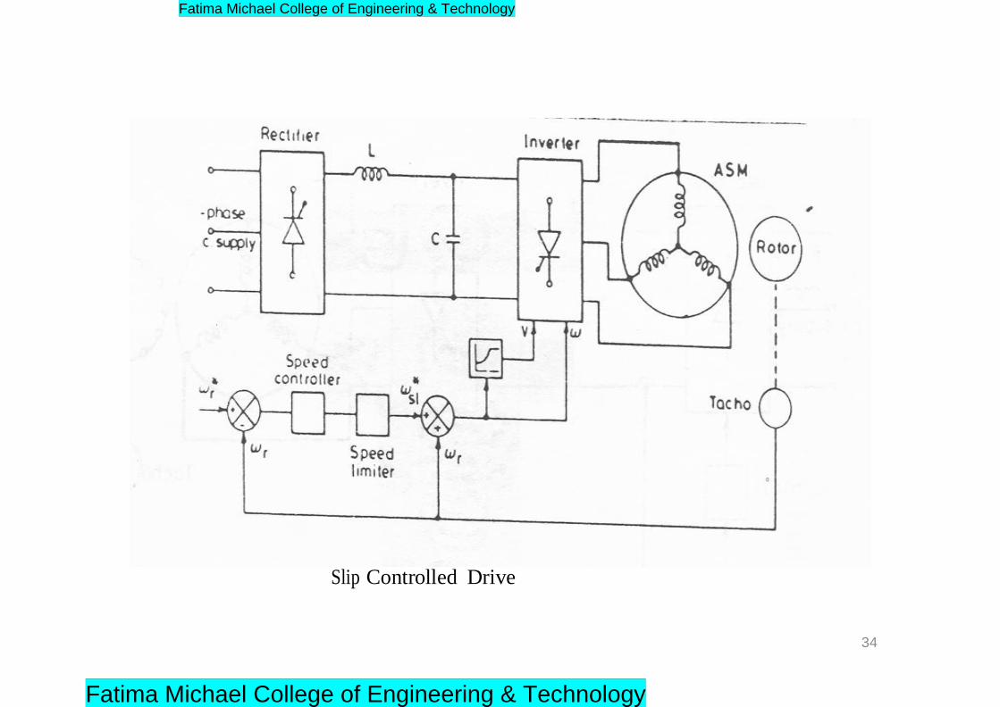
Slip Controlled Drive
34
Fatima Michael College of Engineering & Technology
Fatima Michael College of Engineering & Technology
Features of Slip Controlled Drives
Highly Efficient
Precise and accurate control of torque is possible in the complete speed range.
The slip frequency can be any value up to the value corresponding to break down torque from no load slip.
Stable operation with good pf.
Drive efficiency is comparable to a thyristorized dc drive.
High power to Weight ratio, least maintenance, low inertia, no limitations on power and speed ranges.
Selective harmonic elimination is possible.
35
Fatima Michael College of Engineering & Technology
Fatima Michael College of Engineering & Technology
References
• Bimal K. Bose. „Modern Power Electronics and AC
Drives‟, Pearson Education, 2002.
• G.K. Dubey, „Power semi-conductor controlled drives‟, prentice hall of india, 1989.
36
Fatima Michael College of Engineering & Technology
Fatima Michael College of Engineering & Technology

UNIT-V
SYNCHRONOUS MOTOR DRIVES
1
Fatima Michael College of Engineering & Technology
Fatima Michael College of Engineering & Technology

Contents
Open loop volts/HZ speed control of synchronous
motors.
Self control.
Separate control.
Attractive feature of a synchronous motor.
Synchronous motor operating with square wave
inverter
Synchronous motor operating with pwm inverter
Brushless excitation of synchronous machine
2
Fatima Michael College of Engineering & Technology
Fatima Michael College of Engineering & Technology
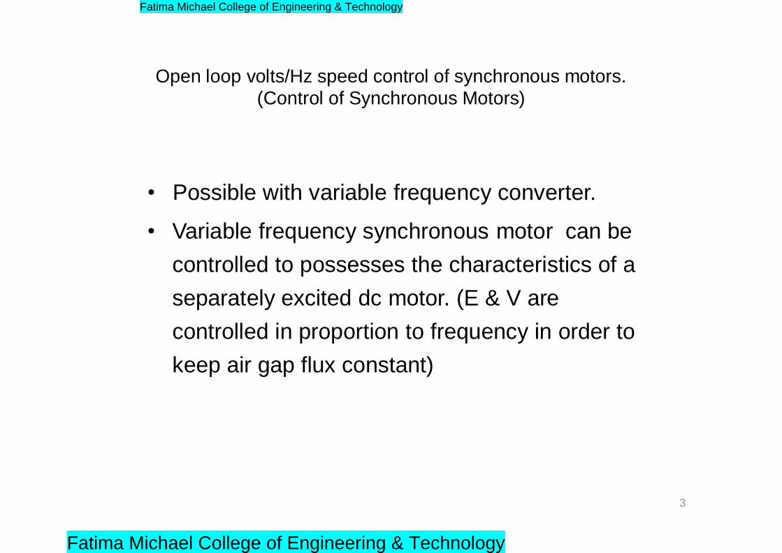
Open loop volts/Hz speed control of synchronous motors.
(Control of Synchronous Motors)
• Possible with variable frequency converter.
• Variable frequency synchronous motor can be
controlled to possesses the characteristics of a
separately excited dc motor. (E & V are
controlled in proportion to frequency in order to
keep air gap flux constant)
3
Fatima Michael College of Engineering & Technology
Fatima Michael College of Engineering & Technology
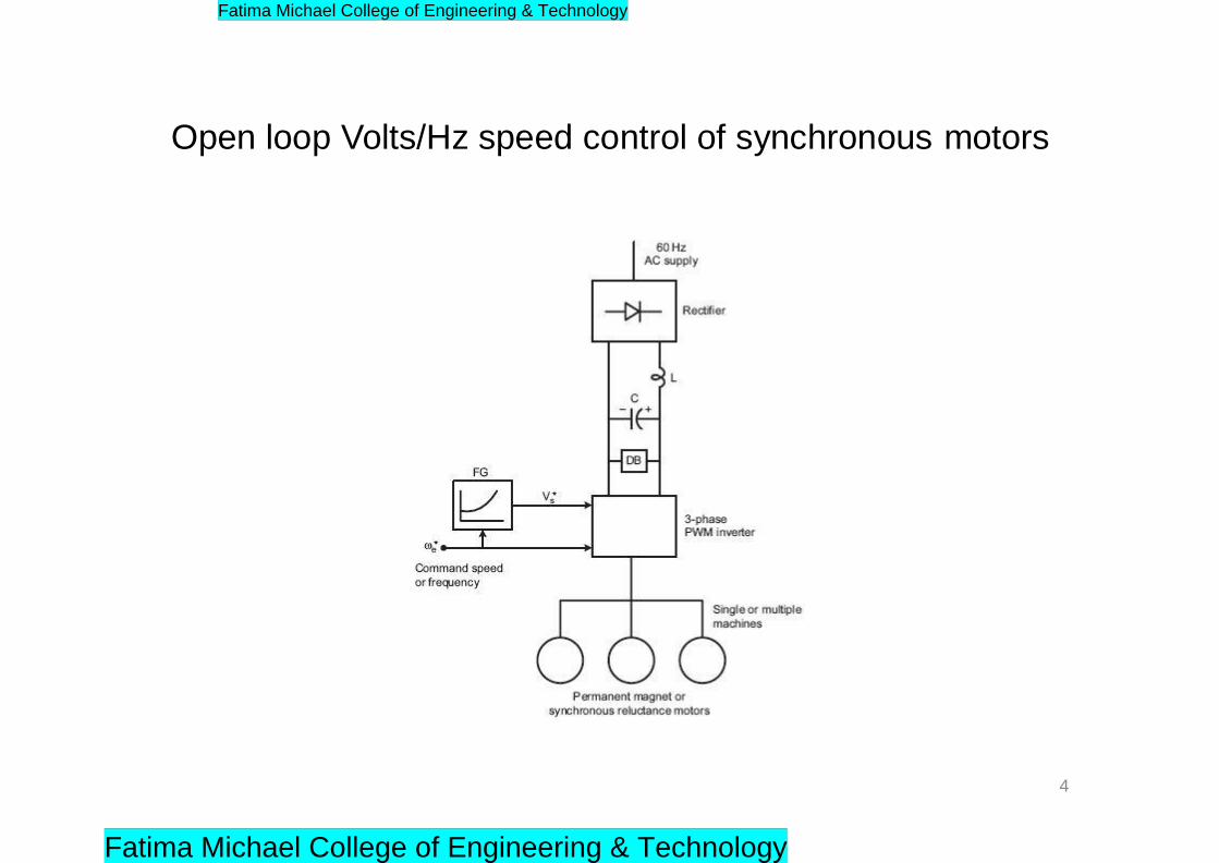
Open loop Volts/Hz speed control of synchronous motors
4
Fatima Michael College of Engineering & Technology
Fatima Michael College of Engineering & Technology
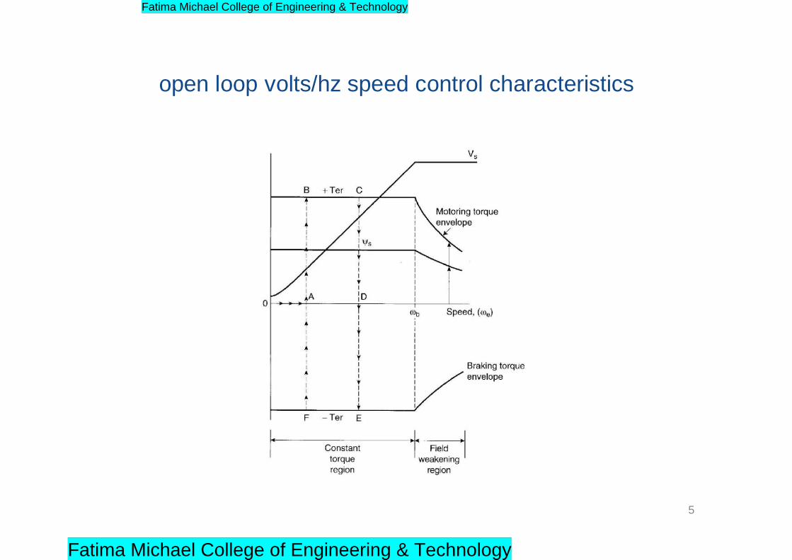
open loop volts/hz speed control characteristics
5
Fatima Michael College of Engineering & Technology
Fatima Michael College of Engineering & Technology
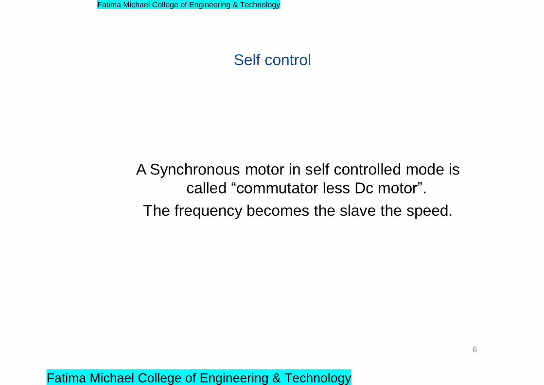
Self control
A Synchronous motor in self controlled mode is
called “commutator less Dc motor”.
The frequency becomes the slave the speed.
6
Fatima Michael College of Engineering & Technology
Fatima Michael College of Engineering & Technology
Basic features of self-controlled synchronous machine
• The inverter, controller and absolute position encoder - act as
electronic commutator
• Electronic commutator replaces the mechanical commutators and
brushes (mechanical inverter) of traditional dc machine
• The flux phasor diagram rotate at synchronous speed
7
Fatima Michael College of Engineering & Technology
Fatima Michael College of Engineering & Technology

Basic features of self-controlled synchronous machine
• Control can modify the angle between the flux phasors
• Because of self-control, machine does not show any stability
or hunting problem of traditional synchronous machine
• The transient response is fast – similar to dc machine
• The rotor inertia is smaller than dc machine with high energy
magnet
8
Fatima Michael College of Engineering & Technology
Fatima Michael College of Engineering & Technology
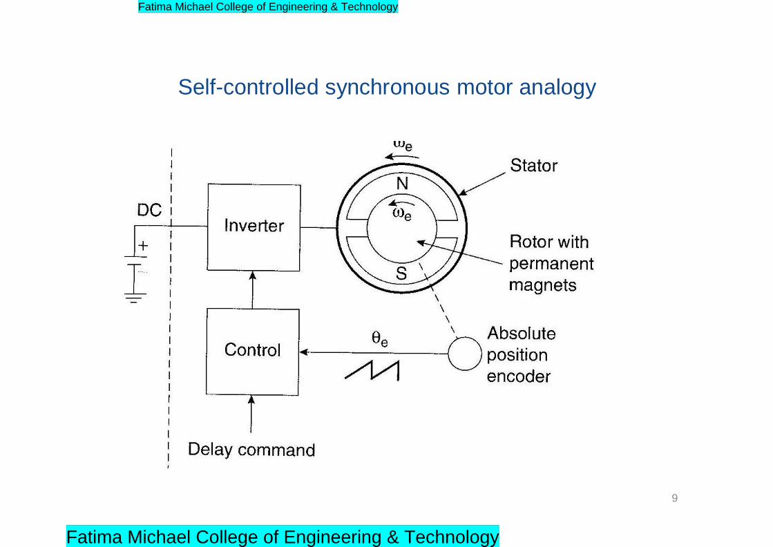
Self-controlled synchronous motor analogy
9
Fatima Michael College of Engineering & Technology
Fatima Michael College of Engineering & Technology
Self Control Principle
• Commutation of the converter feeding the motor is controlled through the rotor position information from a shaft encoder.
• Under over excitation the motor voltages can be employed to commutate the thyristors at the inverter. Now the inverter becomes simple. But at low speeds commutation assistance is required.
10
Fatima Michael College of Engineering & Technology
Fatima Michael College of Engineering & Technology
• Rotor position is sensed and the firing signals to
the devices are synchronized to the motor
position.
• For every 600 rotation of the rotor a new device in the sequence is fired.
Contd..
11
Fatima Michael College of Engineering & Technology
Fatima Michael College of Engineering & Technology

• For rotation of the rotor by 2 pole pitches all the six devices will receive firing pulses.
• Using this control the angle between the rotor and the stator mmf (Torque Angle) can be controlled. This is not possible in separately excited motor.
• Synchronous motor in self control is called as Commutator less motor having the steady state performance of the separately excited DC motor
12
Fatima Michael College of Engineering & Technology
Fatima Michael College of Engineering & Technology
Separate control
The speed is the slave the frequency.
13
Fatima Michael College of Engineering & Technology
Fatima Michael College of Engineering & Technology
Separate control principle
• Supply Frequency to the synchronous motor is
controlled from the inverter which receives its firing
pulses from a frequency controlled oscillator.
• The machine will exhibits conventional behavior.
• Up to base speed the motor operates at constant
torque and above base speed are obtained by
clamping the voltage at rated voltage. Frequency
can be increased and the motor operates in flux
weakening region
14
Fatima Michael College of Engineering & Technology
Fatima Michael College of Engineering & Technology
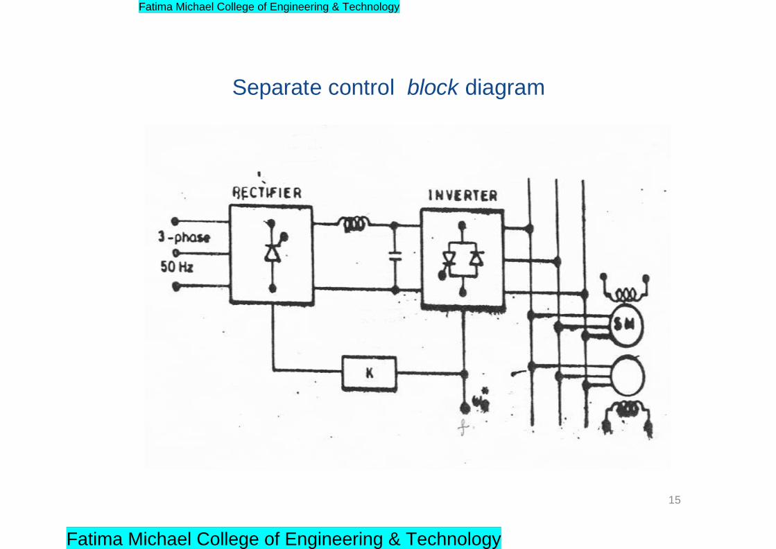
Separate control block diagram
15
Fatima Michael College of Engineering & Technology
Fatima Michael College of Engineering & Technology

Draw backs of Separate control
• Hunting
• Poor dynamic Behavior.
16
Fatima Michael College of Engineering & Technology
Fatima Michael College of Engineering & Technology
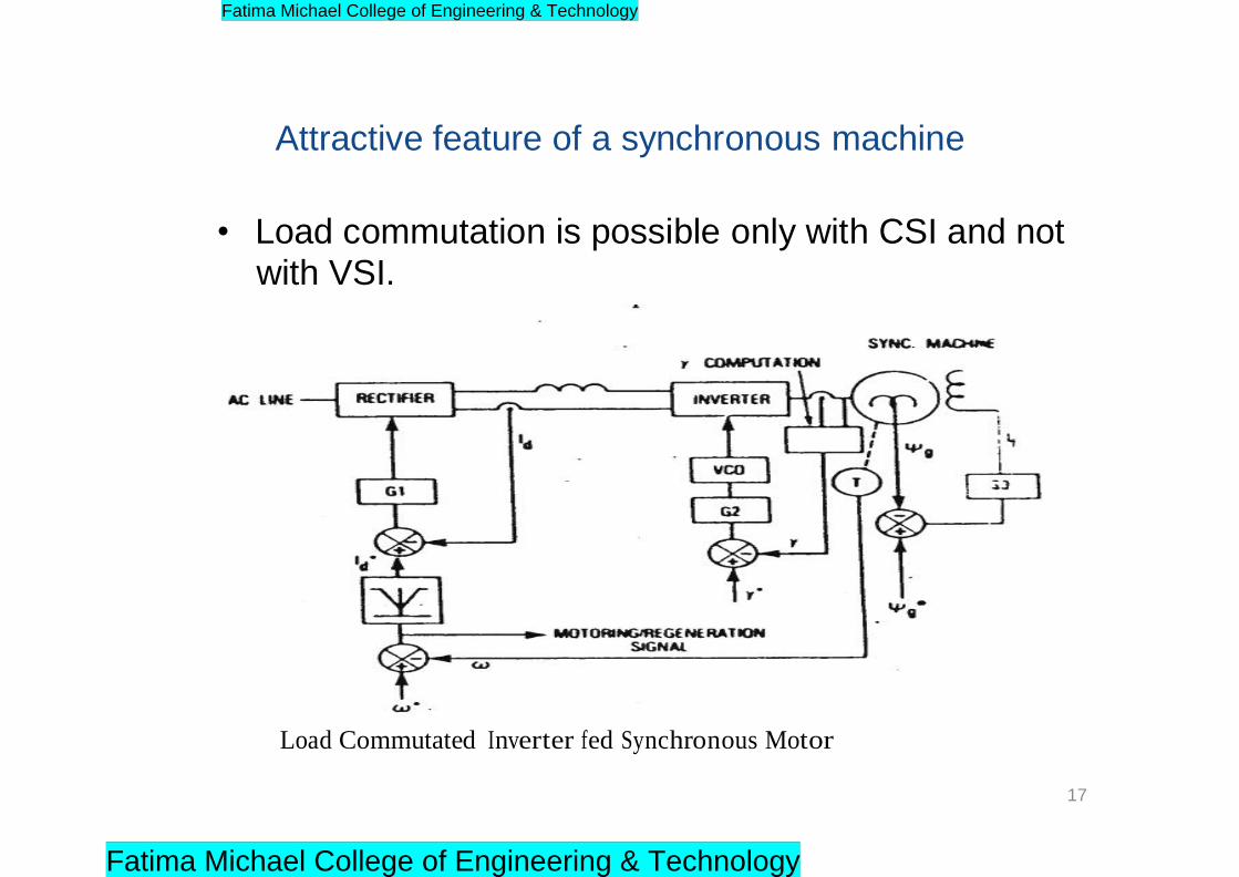
Attractive feature of a synchronous machine
• Load commutation is possible only with CSI and not with VSI.
Load Commutated Inverter fed Synchronous Motor
17
Fatima Michael College of Engineering & Technology
Fatima Michael College of Engineering & Technology

• When forced commutation is required, the motor may be
operated at UPF.
• To provide the necessary reactive power of the converter
when the motor is over excited
• Load Commutation can be used when the cycloconverter
is feeding the motor. When using cycloconverter,
commutation difficulty is over come by utilising line
commutation.
18
Fatima Michael College of Engineering & Technology
Fatima Michael College of Engineering & Technology
Synchronous motor operating with square wave
inverter
19
Fatima Michael College of Engineering & Technology
Fatima Michael College of Engineering & Technology
Synchronous motor operating with square wave inverter
• Speed Range
– Medium to High
• Braking
– Dynamic Braking Possible. Regeneration not
straight forward.
• Harmonics
– Heating effect is high at lower frequency
Contd..
20
Fatima Michael College of Engineering & Technology
Fatima Michael College of Engineering & Technology

• Torque Pulsations
–Problem at Low speed • Power Factor
–Low Line pf
• High Cost
• Efficiency
–Moderately good • Open loop Control is possible.
• Staring by cage winding or by open loop method
Contd..
21
Fatima Michael College of Engineering & Technology
Fatima Michael College of Engineering & Technology
Synchronous motor operating with
pwm inverter
22
Fatima Michael College of Engineering & Technology
Fatima Michael College of Engineering & Technology
Features
• Speed Range
– Very wide Speed range upto zero speed is possible
• Braking
– Dynamic Braking Possible. Regeneration possible if primary supply is dc.
• Harmonics
– Nearly Sinusoidal
23
Fatima Michael College of Engineering & Technology
Fatima Michael College of Engineering & Technology
• Torque Pulsations
– Minimal • Power Factor
– Line pf closer to Unity.• High Cost
• Efficiency
– Good• Open loop Control is possible.
24
Fatima Michael College of Engineering & Technology
Fatima Michael College of Engineering & Technology
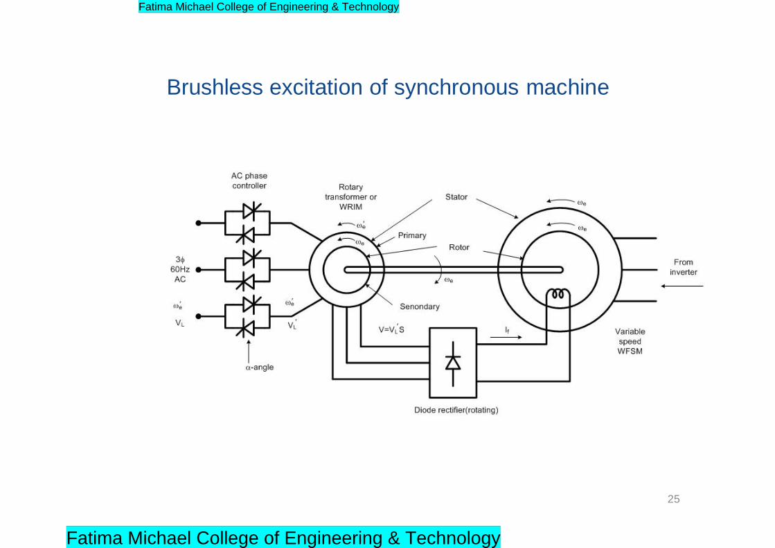
Brushless excitation of synchronous machine
25
Fatima Michael College of Engineering & Technology
Fatima Michael College of Engineering & Technology

References
• Bimal K. Bose. „Modern Power Electronics and AC
Drives‟, Pearson Education, 2002.
• G.K. Dubey, „Power semi-conductor controlled drives‟, prentice hall of india, 1989.
26
Fatima Michael College of Engineering & Technology
Fatima Michael College of Engineering & Technology