ee 508 lecture 4 - iowa state universityclass.ece.iastate.edu/ee508/lectures/ee 508 lect 25 fall...
TRANSCRIPT

EE 508
Lecture 25
Integrator Design

Parasitic Capacitances on Floating Nodes
CP1
CP2
Z1
Z2
Zk
CP
Parasitic capacitances ideally have no affect on filter when on a non-floating
node but directly affect transfer function when they appear on a floating node
Parasitic capacitances are invariably large, nonlinear, and highly process
dependent in integrated filters. Thus, it is difficult to build accurate integrated
filters if floating nodes are present
Generally avoid floating nodes, if possible, in integrated filters
Floating Node
Not Floationg Node
Review from last time

VOUT
VIN
R3 R1 R2
C1
C2
C1
C2
R2
R1
VIN
VOUT-K
C1
C2
R2
R1
VIN
VOUTK
R3
R0
R1 RQ
RA
RAR2
C1 C2
VOUT
VIN
Sallen-Key Type (Dependent Sources)
Infinite Gain Amplifiers
Integrator Based Structures
Which type of Biquad is really used? Floating NodeNot Floationg Node
Review from last time

Filter Design/Synthesis Considerations
T1(s)
Biquad
T2(s)
Biquad
Tk(s)
Biquad
VOUTVIN Tm(s)
Biquad
1 2 mT s T T T
I1(s)
Integrator
I2(s)
Integrator
I3(s)
Integrator
I4(s)
Integrator
Ik(s)
Integrator
VIN
VOUTIk-1(s)
Integrator
a2a1
T1(s)
Biquad
T2(s)
Biquad
Tk(s)
Biquad
αF
XOUTXIN
α1α2 αk
α0
Cascaded Biquads
Leapfrog
Multiple-loop Feedback – One type shown
Observation: All filters are comprised of summers, biquads and integrators
And biquads usually made with summers and integrators
Integrated filter design generally focused on design of integrators, summers, and
amplifiers (Op Amps)
Will now focus on the design of integrators, summers,
and op amps
Review from last time

Basic Filter Building Blocks (particularly for integrated filters)
• Integrators
• Summers
• Operational Amplifiers

Integrator Characteristics of Interest
0I
s
XOUTXIN
0II s = s
0II jω = ω
I 0jω = -90
Unity Gain Frequency = 1
Properties of an ideal integrator:
Gain decreases with 1/ω
Phase is a constant -90o
0I Ij = 1
How important is it that an integrator have all 3 of these properties?

Integrator Characteristics of Interest
0I
s
0I
sXIN
α
XO1
XO2
20
2 20 0
- IT s
s + αI s + I
0 0ω = I
1Q =
0I
s
XOUTXIN 0II s = s
0II jω = ω I 0jω = -90
How important is it that an integrator have all 3 of these properties?
Consider a filter example:
In many (most) applications it is critical that an integrator be very nearly ideal
(in the frequency range of interest)
0I Ij = 1
Band edges proportional to I0
Phase critical to make Q expression valid


Some integrator structures
VOUT
C
VINR
I s 1
RCs
Are there other integrator structures?
Inverting Active RC Integrator
VOUT
VIN
C
gm
IOUT I
I
OUT m IN
OUT OUT
= - g V
1V
sC
I s mg
sC0I mg
C
Termed an OTA-C or a gm-C integrator
0I1
RC

Some integrator structures
Are there other integrator structures?
C
VOUT
VINgm
IOUT
VBB
I
I
OUT m IN
OUT OUT
= g V
1V
sC
I s mg
sC
Termed a TA-C integrator
VOUT
C
VINRMOS
VC
gmV1C
VOUT
V1
VIN
IOUT
I s MOS
1
sCR
Termed MOSFET-C integrator
0I mg
C
0IFET
1
R C

Some integrator structures
Are there other integrator structures?
INI
2 1
2 1OUT
1V = V
sC
V - VI
R
OUT
IN
II s
I
1
sRC
Termed active RC current-mode integrator
IIN
IOUT
R
C
ZL
V1
V2
• Output current is independent of ZL
• Thus output impedance is ∞ so provides current output
0I1
RC

Some integrator structures
I s 1
sRC
IIN
IOUT
R
C
ZL
V1
V2
C
VOUT
VINgm
IOUT
VBB
VOUT
C
VINR
VOUT
C
VINRMOS
VC
VOUT
VIN
C
gm
IOUT
I s 1
sRC
I s MOS
1
sR C
I s mg
sC
I s mg
sC
There are many different ways to build an inverting integrator
There are other useful integrator structures (some will be introduced later)
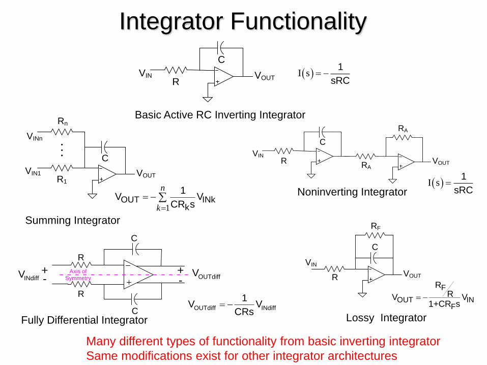
Integrator Functionality
VOUT
C
VINR
I s 1
sRC
VOUT
C
VIN1R1
VINn
Rn
1OUT INk
k
1V V
CR s
n
k
C
C
R
R
OUTdiffVINdiffV +
-+-
Axis of
Symmetry
OUTdiff INdiff
1V V
CRs
C
VINR VOUTRA
RA
I s 1
sRC
VIN
VOUTR
C
RF
F
OUT INF
RRV V
1+CR s
Summing Integrator
Fully Differential Integrator
Noninverting Integrator
Lossy Integrator
Basic Active RC Inverting Integrator
Many different types of functionality from basic inverting integrator
Same modifications exist for other integrator architectures

Integrator-Based Filter Design
0I
s
0I
sXIN
α
XO1
XO2
IIN
IOUT
R
C
ZL
V1
V2
VOUT
VIN
C
gm
IOUT
C
VOUT
VINgm
IOUT
VBB
VOUT
C
VINRMOS
VC
VOUT
C
VINR
I1(s)
Integrator
I2(s)
Integrator
I3(s)
Integrator
I4(s)
Integrator
Ik(s)
Integrator
VIN
VOUTIk-1(s)
Integrator
a2a1
Any of these different types of integrators can be used to build integrator-based filters
T1(s)
Biquad
T2(s)
Biquad
Tk(s)
Biquad
VOUTVIN Tm(s)
Biquad
T0(s)First-
Order

Are new integrators still being invented?


Example – OTA-C Tow Thomas Biquad
VOUT
VIN
C
gm
IOUT
0I
s
0I
sXIN
α
XO1
XO2
1OUT 2 m2V sC =g V
C1
gm1
VOUT
C2
gm2
gm3
gm4
VIN
V1
1 1 m1 OUT m3 IN m4 1V sC = -g V g V g V
OUT m3 m2
2IN 1 2 m4 2 m1 m2
V g g=
V s C C sg C +g g
2
m3 m2
mOUT
2IN 2 m4 m m
2
m
g g
g CV=
V g g gs s +
g C C
Assume gm1=gm2=gm, C1=C2=C
2
0
200
Q
m3
mOUT
2IN
gω
gV=
V ωs s +ω
0 mg
ω = C
m
m4
gQ =
g
express as
where

0I
s
XOUTXIN
0I
s + α
XOUTXIN
0I
s
XOUTXIN
0I
s + α
XOUTXIN
XOUT
XIN1
XINk0kI
s
XINn
1
OkOUT
IX
s
n
k
XOUT
XIN1
XINk0k
k
I
s+
XINn
1
OkOUT
k
IX
s+α
n
k
Noninverting Inverting
Lossy Noninverting Lossy Inverting
Summing (Multiple-Input) Inverting/Noninverting
Summing (Multiple-Input) Lossy Inverting/Noninverting
0I
s
Balanced Differential
IN+X
IN-X
OUT+X
OUT-X
OUT OUT IN IN+ + + +0IX X X X
s
0I
s
Fully Differential
INdiffX OUTdiffX
+ +
- -
- -
+ ++ +- - OUTdiff INdiff
0IX Xs
Basic Integrator Functionality

Basic Integrator Functionality
0I
s
XOUTXIN 0I
s
XOUTXIN
Noninverting Inverting
• An inverting/noninverting integrator pair define a family of integrators
• All integrator functional types can usually be obtained from the
inverting/noninverting integrator pair
• Suffices to focus primarily on the design of the inverting/noninverting
integrator pair since properties of class primarily determined by
properties of integrator pair

Example – Basic Op-Amp Feedback Integrator
VOUT
C
VINR
C
VINR VOUTRA
RA
Inverting Integrator of Family Noninverting Integrator
VOUT
C
VIN1R1
VINn
Rn
Summing Inverting Integrator
1OUT INk
k
1V V
CR s
n
k
OUT IN1
V VCRs
OUT IN
1V V
CRs

Example – Basic Op-Amp Feedback Integrator
VOUT
C
VINR
Inverting Integrator of Family VOUT
C
VIN1R1
VINn
Rn
Summing Inverting Integrator
1OUT INk
k
1V V
CR s
n
k
OUT IN1
V VCRs
VOUT
C
VIN1R1
VINn
Rn
Rn-1VINn-1
Lossy Summing Inverting Integrator
1
1
nINk
kOUT
n
RV
RV
1+CR s
n
k
VOUT
C
VIN1R1
VINn
RnRF
1
FINk
kOUT
F
RV
RV
1+CR s
n
k

Example – Basic Op-Amp Feedback Integrator
VOUT
C
VINR
Inverting Integrator of Family
OUT IN1
V VCRs
Lossy Summing Inverting Integrator
VOUT
C
VIN1R1
VINn
RnRF
1
FINk
kOUT
F
RV
RV
1+CR s
n
k
VIN
VOUTR
C
RF
Lossy Inverting Integrator
F
OUT INF
RRV V
1+CR s

Example – Basic Op-Amp Feedback Integrator
VOUT
C
VINR
Inverting Integrator of Family
OUT IN1
V VCRs
Balanced Differential Inverting Integrator
C
R
C
R
IN+V
IN-V
OUT+V
OUT-V
+
-
+
-
INdiffV OUTdiffVAxis of
Symmetry
OUT IN
1V V
CRs
OUT IN
1V V
CRs
OUTdiff INdiff
1V V
CRs

Example – Basic Op-Amp Feedback Integrator
VOUT
C
VINR
Inverting Integrator of Family
OUT IN1
V VCRs
Fully Differential Inverting Integrator
OUTdiff INdiff
1V V
CRs
C
C
R
R
OUTdiffVINdiffV +
-+-
Axis of
Symmetry

Integrator Types
0I
s
VOUTVIN
Voltage Mode
oOUT IN
IV V
s
0I
s
IOUTIIN
Current Mode
oOUT IN
II I
s
0I
s
VOUTIIN
Transresistance Mode
oOUT IN
IV I
s
0I
s
IOUTVIN
Transconductance Mode
oOUT IN
II V
s
Will consider first the Voltage Mode type of integrators

Voltage Mode Integrators
• Active RC (Feedback-based)
• MOSFET-C (Feedback-based)
• OTA-C
• TA-C
• Switched Capacitor
• Switched Resistor
Sometimes termed “current mode”
Will discuss later

Active RC Voltage Mode Integrator
VOUT
C
VINR
OUT IN1
V VCRs
• Limited to low frequencies because of Op Amp limitations
• No good resistors for monolithic implementations Area for passive resistors is too large at low frequencies
Some recent work by Haibo Fei shows promise for some audio frequency applications
• Capacitor area too large at low frequencies for monolithic implementatins
• Active devices are highly temperature dependent, proc. dependent, and nonlinear
• No practical tuning or trimming scheme for integrated applications with passive resistors

MOSFET-C Voltage Mode Integrator
• Limited to low frequencies because of Op Amp limitations
• Area for RMOS is manageable !
• Active devices are highly temperature dependent, process dependent
• Potential for tuning with VC
• Highly Nonlinear (can be partially compensated with cross-coupled input
VOUT
C
VINRMOS
VC
MOS
OUT IN1
V VCR s
A Solution without a Problem

MOSFET-C Voltage Mode Integrator
• Improved Linearity
• Some challenges for implementing VC
VOUT
C
VINRMOS
VC
MOS
OUT IN1
V VC R s
Still A Solution without a Problem
MOS
OUT IN1
V VC R s
VOUT
C
VIN RMOS
VC
VC

OTA-C Voltage Mode Integrator
• Requires only two components
• Inverting and Noninverting structures of same complexity
• Good high-frequency performance
• Small area
• Linearity is limited (no feedback in integrator)
• Susceptible to process and temperature variations
• Tuning control can be readily added
Widely used in high frequency applications
Noninverting Inverting
V O U T
V IN
C
gm
m
O U T IN
gV V
sC
VOUTVIN
C
gm
m
O U T IN
gV V
sC

OTA-C Voltage Mode Integrator
Programmable Integrator
VOUTVIN
C
gm
IABC
m
O U T IN
gV V
sC
m A B Cg f I
VOUTVIN
C
gm
m
O U T IN
gV V
sC

OTA-C Voltage Mode Integrator
Lossy Integrator
OUT m F
IN F
V s g R =
V s 1+s R C
But RF is typically too large for integrated applications
VOUTVIN
C
gm
m
O U T IN
gV V
sC
VOUT
VIN
C
gm
RF

End of Lecture 25