education-1-4-4
DESCRIPTION
education-1-4-4TRANSCRIPT

American Journal of Educational Research, 2013, Vol. 1, No. 4, 137-142 Available online at http://pubs.sciepub.com/education/1/4/4 © Science and Education Publishing DOI:10.12691/education-1-4-4
The Case Study of Simulation of Power Converter Circuits Using Psim Software in Teaching
Hemant Mehar*
Electrical & Electronics Engineering Department IES, IPS Academy, Indore, MP, India *Corresponding author: [email protected]
Received April 21, 2013; Revised May 19, 2013; Accepted May 20, 2013
Abstract Involvement of software in teaching is provide a batter support, more clear and visual operation of complex circuits and waveforms to the faculty of power electronics in classroom teaching. The software packages available for simulation of power electronic circuits are MATLAB, PSPICE and PSIM and many more. Use of the software in classroom teaching is provide an additional support to the faculty and its better then the time consuming black board practice. This paper provides a case study of power electronics circuits in PSIM software. Different power electronics converters model are prepared on PSIM software and generate simulation waveforms. This paper is helpful for the faculty of electrical engineering to find the applications of PSIM in teaching.
Keywords: PSIM, simulation, power electronics, electrical, teaching
1. IntroductionIn the present trends, Power electronics is one of the
most important subjects of electrical engineering. Power electronics technology involved various types of converters. These converters are the application of circuit theory and design techniques, the development of analytical tools toward efficient electronic conversion, control, and conditioning of electric power. The typical undergraduate syllabus will have topics like uncontrolled and controlled rectifiers with R, RL loads; choppers; single-phase and 3-phase inverters; AC voltage controllers, etc. [1]. A simulation practice is providing a platform the student to work efficiently in the present and future design industry because due to the advanced development in technology, simulation process is very useful. Here the simulation of converters is presented using PSIM software.
2. PSIM for SimulationThe basic PSIM process in represented in the Figure 1.1.
A circuit is represented in PSIM in four blocks: power circuit, control circuit, sensors, and switch controllers.
The power circuit consists of switching devices, RLC branches, transformers, and coupled inductors. The control circuit is represented in block diagram. Components in s-domain and z domain, logic components (such as logic gates and flip-flops), and non-linear components (such as multipliers and dividers) are used in the control circuit. Sensors are used to measure power circuit quantities and pass them to the control circuit. Gating signal is then generated from the control circuit
and sent back to the power circuit through switch controllers to control switches.
Figure 1.1. PSIM Process
3. Simulation in Power Electronics
3.1. Diode Characteristics Diodes are active devices constructed to allow current
to flow in one direction. The diode consists of N-type and P-type materials The N-type material is called the cathode and the P-type material is called the anode. There are two types of biasing that can be applied to a diode. For a diode to be forward biased, a power supply is connected with the positive terminal to the P-type material (anode) and the negative terminal to the N-type material (cathode). The graph below shows the electrical characteristics of a typical diode. When a small voltage is applied to the diode in the forward direction, current flows easily. For a diode to be reversed biased, the power supply leads are set up with the negative terminal attached to the P-type material and the positive terminal attached to the N-type material.

138 American Journal of Educational Research
When voltage is applied in the reverse direction through a diode, the diode will have a great resistance to current
flow. Different diodes have different characteristics when reverse-biased.
Figure 3.1. Simulation modal of Diode Characteristics
Figure 3.2. Waveform of Diode Characteristics
3.2. Diode Rectifiers Rectifiers are mainly used in power supplies where an AC signal is to be converted to DC. The DC
voltage is obtained by passing the rectifier’s output through a filter to remove the ripple (AC components). There are many possible ways to construct rectifier circuits using diodes. The three basic types of rectifier circuits are: The Half Wave Rectifier The Full Wave Rectifier The Bridge Rectifier In such diode rectifiers, the power flow can be only
from the utility ac side to the dc side. A majority of the power electronics applications use such as switching dc power supplies, ac motor drives, dc servo drives and so on use such uncontrolled rectifiers. in this simulation model capacitor filter are use to filtered the ripple content in the output of the rectifier.
Figure 3.3. Simulation modal of Single Phase Uncontrolled Bridge Rectifier
Figure 3.4. Waveforms of Single Phase Uncontrolled Bridge Rectifier
American Journal of Educational Research 139
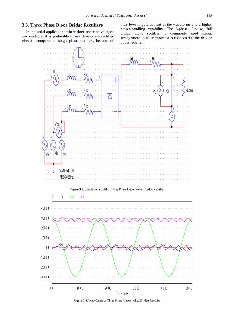
3.3. Three Phase Diode Bridge Rectifiers In industrial applications where three-phase ac voltages
are available, it is preferable to use three-phase rectifier circuits, compared to single-phase rectifiers, because of
their lower ripple content in the waveforms and a higher power-handling capability. The 3-phase, 6-pulse, full bridge diode rectifier is commonly used circuit arrangement. A filter capacitor is connected at the dc side of the rectifier.
Figure 3.5. Simulation modal of Three Phase Uncontrolled Bridge Rectifier
Figure 3.6. Waveforms of Three Phase Uncontrolled Bridge Rectifier

140 American Journal of Educational Research
3.4. Thyristor Converters For given ac input voltages, the magnitude of the
average output voltage in thyristor converters can be
controlled by delaying the instants at which the thyristors are allowed to start conduction.
Figure 3.7. Simulation modal of Three Phase controlled Rectifier
Figure 3.8. Simulation modal of Three Phase controlled Rectifier
3.5. Single Phase Half-Controlled Bridge Rectifier
A single-phase semi converter bridge consists of two diodes and two thyristors. The load is of RLE type. With
T1 on, load gets connected to source through T1 and D1. For the period wt=45 to 180, load current flows through T1 and D1 and output Vo is of same wave shape as Vs. after wt=180 load voltage tends to reverse as ac voltage changes polarity. There is limited control over the level of dc output voltage.

American Journal of Educational Research 141
Figure 3.9. Simulation model of Single Phase Half-Controlled Bridge Rectifier
Figure 3.10. Simulation model of Single Phase Half-Controlled Bridge Rectifier
3.6. Single Phase Fully Controlled Bridge Rectifier
A single-phase full converter bridge consists of four SCRs as shown. Thyristor pair T1 and T2 is simultaneously triggered and 180 later, pair T3 and T4 is gated together. Voltage at the output terminals can be controlled by adjusting the firing angle delay of the thyristors. There is a wider control over the level of dc output voltage.
Figure 3.11. Simulation model of Single Phase Fully Controlled Bridge Rectifier
Figure 3.12. Waveforms of Single Phase Fully Controlled Bridge Rectifier
4. Advantages & Limitations The following advantages derived when using PSIM in
teaching power electronics courses: 1. It provides better visual operation of power
electronics converters. 2. Use of software in classroom save the time of the
faculty. 3. With its user-friendly interface, its simulation speed,
its capability of simulating any type of power converters and control circuits.
4. Students can use this software for their project works. This paper provides a basic approach to deal with the software.
The Only Limitation with this software approach is that the knowledge of computer and depth knowledge of power electronics subject is necessary to identify the truth results.
5. Conclusion This case study provides the visual operations of power
electronics converters. As power electronic systems are getting more complex today, the simulation used for education is requiring more features. This approach is time saving and some directions in the development of simulation are discussed in this paper, with the help of present model students can simulate the power electronics circuit with various load & conditions.
Reference [1] Hemant Mehar, “MATLAB Simulation Techniques in Power
Electronics”, IEEE Technology and Engineering Education (ITEE), VOL. 7, NO.4 December, 2012, Page No. 62.
[2] Hemant Mehar, “Software Application In Under Graduate Electrical Engineering Education”, International Journal of Engineering Research & Technology (IJERT), Vol. 1 Issue 10, December- 2012.
[3] Prof. Sabyasachi Sengupta and et.all, “NPTEL Power Electronics Notes” [Online]. Available: nptel.iitm.ac.in.
[4] Chung Kuo, Jack Hsieh, Firuz Zare, Senior Member IEEE, Gerard Ledwich, Senior Member IEEE “An Interactive Educational Learning Tool for Power Electronics” Conf. Power Engineering, 2007Australasian Universities, AUPEC 2007.
[5] P.J. van Duijsen; P.Bauer; B. Davat; “Simulation and Animation of Power Electronics and Drives, Requirements for Education” [Online]. Available: www.simulation-research.com.
[6] Sameer Khader “The Application of PSIM & MATLAB/SIMULINK in power electronics courses”, Conf. "Learning Environments and Ecosystems in Engineering

142 American Journal of Educational Research
Education"; IEEE Global Engineering Education Conference (EDUCON) – April 4-6, 2010, Amman, Jordan.
[7] I.G. Pacheco, J.G. Matias, “A Methodology Based on Effective Practices to Develop Educational Software”, in Computaciony Sistemas, Vol. 11, No. 4, 2008, pp. 313-332.
[8] Rajesh Verma, Ashu Gupta and Kawaljeet Singh, “Simulation Software Evaluation and Selection: A Comprehensive Framework”, J. Automation& Systems Engineering2-4 (2008): 221-234.
[9] I.G. Pacheco, J.G. Matias, “A Methodology Based on Effective Practices to Develop Educational Software”, in Computacion y Sistemas, Vol. 11, No. 4, 2008, pp. 313-332.
[10] http://www.powersimtech.com/index.php?name=download. [11] Mohan, Undeland, Robbins, Power Electronics: Converters,
Applications and Design, 2nd Edition.New York: John Wiley & Sons INC., 1995.
[12] valery vodovozov, Introduction to power electronics, ventus publishing ApS, 2010 (online:bookboon.com).
[13] Bhimbra, P. S., Power Electronics, 4th Ed., Khanna Publication, 2007.
[14] Muhammad H. Rashid, Power electronics, circuit devices and application, 3rd Ed., pearson education Inc., 2007.
[15] P.C. Sen, Power electronics, Tata McGraw-Hill publishing company, 2008.
[16] BK khanchandani, Power electronics, Tata McGraw-Hill publishing company, 2008
[17] N. Mohan, T. Undeland, W. Robbins, Power electronics: Converters,applications and designs, John Wiley and Sons, 1989.
[18] Martins M.J., M. Robert and J.M. Thiriet, “A thematic network contribution to education and training in electrical and information engineering in Europe”, 4th ITHET'03 Conference, Marrakech, Morocco, 2003 July 7-9 (CD-ROM).
[19] Thiriet J.M., M. Robert, P. Lappalainen, M. Hoffmann, M. J. Martins and A. Seoane, “Toward a pan-European virtual university in Electrical and Information Engineering”, IEEE Trans. On Education, Vol.45, n. 2, May 2002, pp.152-160.
[20] Palit, S.K., Electronic engineering education in India. Proc. 1st Asia-Pacific Forum on Engng. And Tech. Educ., Monash University, Melbourne, Australia, 50-54 (1997).
[21] Palit, S.K., Voumard, P. and Ito, K., Electrical and electronic engineering education in the Asia-Pacific Region. Proc. 1st Asia-Pacific Forum on Engng. and Tech. Educ., Monash University, Melbourne, Australia, 153-157 (1997).
[22] Vidyasagar, M., Patel, V.V., and Deodhare, G.S., Control education: a world showcase. IEEE Control Systems, 16, 2, 30-33 (1996).
[23] Palit, S.K., Mani, N. and Lithgow, B., Computeraided undergraduate electronic study programme. Proc. Pacific Region Conf. on Electrical Engng. Educ. (PRCEEE,97), Wollongong University, NSW, Australia, 163-168 (1997).
[24] Palit, S.K., and Reid, M, Application of Pspice in the teaching of undergraduate electronics. Proc. Pacific Region Conf. on Electrical Engng. Educ. (PREEE,97), Wollongong University, NSW, Australia, 181-186 (1997).
[25] Maheshwari, L.K., A decade of university-industry linkages in electronics and instrumentation engineering at BITS. IEEE Trans on Educ., 34, 4 (1991).