e:dropbox01 jawa studio las vegas 7x35 wood smith …...107 e. charleston suite 250 ... \dropbox\01...
TRANSCRIPT

tel. 702.598.1723
fax. 702.598.1724
mail@jawastudio com
107 E. Charleston Suite 250
Las Vegas NV 89104
3/16
/201
8 11
:45:
26 A
ME:
\Dro
pbox
\01
JAW
A ST
UD
IO L
AS V
EGAS
\201
6\16
057
Hel
ler C
ompa
nies
- Su
nset
Site
\160
57 h
elle
r com
pani
es -
suns
et b
usin
ess
cent
er c
d re
v2.rv
t
.
Sunset Business Center
12/05/2017

1. drawings represent the desired result of construction. the method of construction and the risks involved during construction are the responsibility of the contractor. the contractor shall maintain the bldg's structural integrity at all stages of construction
2. the contractor shall verify all dimensions and elevations prior to commencement of work. discrepancies in dimensions shall be brought to the architects notice for his decision before proceeding with work in the affected area.
3. contractors shall follow sizes in the construction documents or figures on the drawings in preference to scale measurements. follow detail drawings in preference to general drawings.
4. where it is obvious that a drawing illustrates only a part of a given work or of a number of items. the remainder shall be deemed repetitive and so constructed.
5. all the contractors proposed substitutions shall be approved by the architect/engineer prior to commencing any pertinent work.
6. architectural drawings shall be used in conjunction with mechanical, plumbing, and electrical drawings.
7. dimensions shown on plans are to the face of the studs or column unless otherwise noted.
8. any omissions or conflicts between various elements on the plans and or specifications shall be brought to the attention of the architect before proceeding with any of the affected work.
9. heights and elevations shown on the plans are from the top the finished slab.
10. contractor responsible for all demolition required to perform work.
general notes
A.F.F. ABOVE FINISHED FLOOR
CLR. CLEAR
DEG. DEGREES
DIA. DIAMETER
EQ. EQUAL
GA. GAUGE
MIN. MINIMUM
MAX. MAXIMUM
N.I.C. NOT IN CONTRACT
O.C. ON CENTER
O.H. OPPOSITE HAND
S.F. SQUARE FEET
SIM. SIMILAR
TYP. TYPICAL
U.O.N. UNLESS OTHERWISE NOTED
V.I.F. VERIFY IN FIELD
abbreviations
code analysis
basis of design
occupancy classification
type of construction
occupant load
B (office), S-1 (Storage)
60% warehouse 40% office
Plans shall comply with 2012 IBC, 2011 NEC, 2012 UMC, 2012 UPC, 2012 IECC, 2014 uniform administrative code, and 2012 local amendments
apn 176-02-501-002
stories
shell: IIIB
fire sprinklers required: Y type: NFPA 13
fire alarm required: N NA
height:
allowable:3 actual:1
allowable:75' actual:32'
area allowable:70,000 actual: Bldg 100 : 45,229 SF Bldg 200: 24,677 SF
required plumbing fixtures
roofing material allowable: any actual: C
fire resistance information occupancy load or building location does not require.
construction area 69,906 SF
limiting occupancy S-1
plumbing to be stubed in for TI at later date 1 unisex accessible restroom per unit min
vicinity map
project site
DETAIL DESIGNATION
SHEET NUMBER
SA3.0-A
100
A1.011
A1.01
G
1A1.01
Exterior Elevation Mark
Section Mark Enlarged Plan
Partition Type
Window Type
Door Mark
symbols
1A1.01
1 Interior Elevation Mark
sheet list
1033 SF
Typical
Warehouse
4
136 SF
Typical Office
2
159 SF
Typical Office
2
127 SF
Typical
Reception
8
Typical
Toilet
circulation
2
2
12
4
A7.01
6
53 SF
Typical Toilet
?
159 SF
Typical Office
160
136 SF
Typical Office
2
3479 SF
Typical
Warehouse
12
127 SF
Typical
Reception
8
2
2
4
4
12
4
egress notes
1
1
number of occupants
direction of egress travel
occupancy load factors
office: 1/100 SFstorage: 1/300 SFassembly: 1/15 SF
building 200
building 100
A3.02 6
7
139 SF
Typical Office
2
139 SF
Typical Office
2
159 SF
Typical Office
2
159 SF
Typical Office
2
59 SF
Typical Toilet
?
58 SF
Typical Toilet
?
2727 SF
Typical
Warehouse
10
1025 SF
Typical
Warehouse
4
117 SF
Typical
Reception
8
118 SF
Typical
Reception
8
2
2
2
2
1212
4 33
4
sheet title:
sheet no.
drawn/checked by:
job no.
date:
ow
ne
r:
pro
jec
t / a
dd
re
ss:
tel. 702.598.1723
fax. 702.598.1724
mail@jawastudio com
107 E. Charleston Suite 150
Las Vegas NV 89104
re
v.:
da
te
:d
esc
rip
tio
n:
and other rights, including copyright.
copyright 2017, jawa studio, ltd.
reuse of the architect's documents
except by mutual agreement in writing.
The owner shall not reuse or permit the
Documents prepared by the architect
are instruments of service for use solely
with respect to this project. The architect
shall retain all common law, statutory
Oc
seal:
consultant:
3/1
6/2
01
8 1
1:4
5:3
0 A
ME:\D
ro
pb
ox\0
1 JA
WA
STU
DIO
LA
S V
EG
AS\2
01
6\1
60
57
H
elle
r C
om
pa
nie
s - Su
nse
t Site
\1
60
57
h
elle
r c
om
pa
nie
s - su
nse
t b
usin
ess c
en
te
r c
d re
v2
.rvt
He
lle
r C
om
pa
nie
s
Su
nse
t Bu
sin
ess C
en
te
r
Su
nse
t R
oa
d
08.08.17
16057
Information Sheet
Author / Checker
A0.00
Sheet No. Sheet Name Issue Date
0.000 . 12/5/2017SK-4 Unnamed 02/02/18
A0.00 Information Sheet 12/5/2017A0.01 Site Plan 12/5/2017A0.02 IECC Energy Compliance 12/5/2017A1.01 Building 100 Floor Plan 12/5/2017A1.02 Building 200 Floor Plan 12/5/2017A1.03 Building 100 Ceiling Plan 12/5/2017A1.04 Building 200 Ceiling Plan 12/5/2017A1.05 Building 100 Roof Plan 12/5/2017A1.06 Building 200 Roof Plan 12/5/2017A2.01 Building 100 Exterior Elevations 12/5/2017A2.02 Building 200 Exterior Elevations 12/5/2017A2.03 Building 100 Enlarged Elevations 12/5/2017A3.01 Enlarged Floor Plans 12/5/2017A3.02 Enlarged Floor Plans 12/5/2017A4.01 Typical Details 12/5/2017A4.02 Typical Details 12/5/2017A4.03 Details 12/5/2017A5.01 Building 100 - Sections 12/5/2017A5.02 Building 100 - Sections 12/5/2017A5.03 Building 200 - Sections 12/5/2017A6.01 Building 100 - Wall Sections 12/5/2017A7.01 Store Fronts 12/5/2017
S0.01 General Structural Notes 08/18/17S1.01 Foundation Plan- Overall 08/18/17S1.02 Foundation Plan- Building 100A 08/18/17S1.03 Foundation Plan- Building 100B 08/18/17S1.04 Foundation Plan- Building 200 08/18/17S2.01 Roof Framing Plan-Overall 08/18/17S2.02 Roof Framing Plan-Building 100A 08/18/17S2.03 Roof Framing Plan-Building 100B 08/18/17S2.04 Roof Framing Plan-Building 200 08/18/17S3.01 Tilt-Up Elevations 08/18/17S3.02 Tilt-Up Elevations 08/18/17S3.03 Tilt-Up Elevations 08/18/17S3.04 Tilt-Up Elevations 08/18/17S3.05 Tilt-Up Elevations 08/18/17S4.01 Typical Tilt Panel Details 08/18/17S4.02 Typical Concrete Details 08/18/17S4.03 Typical Steel Details 08/18/17S5.01 Foundation Details 08/18/17S6.01 Roof Framing Details 08/18/17
M0.00 Mechanical Symbols, Abbreviations and Drawing Index 08/21/17M0.01 Mechanical and Plumbing Specifications 08/21/17M0.02 Mechanical and Plumbing Schedules 08/21/17M0.03 Mechanical and Plumbing Diagrams 08/21/17M2.01 Mechanical Plan First Floor Building 100 08/21/17M2.02 Mechanical Plan First Floor Building 200 08/21/17P2.01 Plumbing Plan First Flooor Building 100 08/21/17P2.02 Plumbing Plan First Flooor Building 200 08/21/17
E0.00 Electrical Symbols, Abbreviations and Drawing List 08/21/17E0.01 Electrical Specifications and Diagrams 08/21/17E0.02 ECC Compliance Statement and Fixture Schedule 08/21/17E0.03 Electrical Single Line Diagram and Panel Schedules 08/21/17E2.01 Lighting Plan Building 100 08/21/17E2.02 Lighting Plan Building 200 08/21/17E2.03 Electrical Plan Building 100 08/21/17E2.04 Electrical Plan Building 200 08/21/17
1/8" = 1'-0"
3 Unit - Building 200 - Typical Egress
1" = 30'-0"
4 Overall Floor Plan
1/8" = 1'-0"
5 Unit- Building 100 - Typical Egress1
1
11
2/0
4/1
7Pla
n C
he
ck C
om
me
nts
7 8 8 8 8 8 8
8
5 8 8
5
67
7
5
18' -
0"
172'
- 10
"75
' - 0
"7'
- 4"
60' -
0"
2' - 4
"
5' - 0
"1
8' - 0
"2
4' - 0
"1
8' - 0
"
T
SUN
SET
RO
AD
44,375 SF
24,610 SF
2
Trash
2 2 2
176-02-501-001M-D
176-02-501-003C-2
176-
02-5
01-0
22
M-D176-02-501-002
M-D
68' -
0"
Building 100
Building 200
163-
35-4
01-0
26M
-D
decorative concrete
decorative concrete
concrete apron
Trash Trash Trash
888864
2' - 4
"4
' - 6
"
24
' - 0
"1
8' - 0
"3
' - 3
"
24' - 0"18' - 0"
3' - 1
0"
4' - 0
"
3' - 1
0"
13
2
8
8
7
7
2
2
422
typ.
7' - 0"
typ.
9' - 0"typ.
21' - 0"
9' - 0
"
4' - 3"
3' - 3"
A3.028
5' - 0
"
24' - 0"
TYP
18' - 0"
60' - 0"
accessible route
accessible route
15
8' - 0
"
1° 48' 59"642.32'
S W
88° 56' 03"335.68'
NE
1° 45' 40"644.07'
N E
88° 37' 52"335.15'
SW
47' -
1"
43' - 11"
76' - 11"area of tenant improvement
area of tenant improvement
loadingloadingloading
10
' - 0
"
25' - 0"
TYP
9' - 0
"
1
1
1
1
1
1
1
1
1
1
1
45' - 11"
24' - 0"
1
1
1
1
1
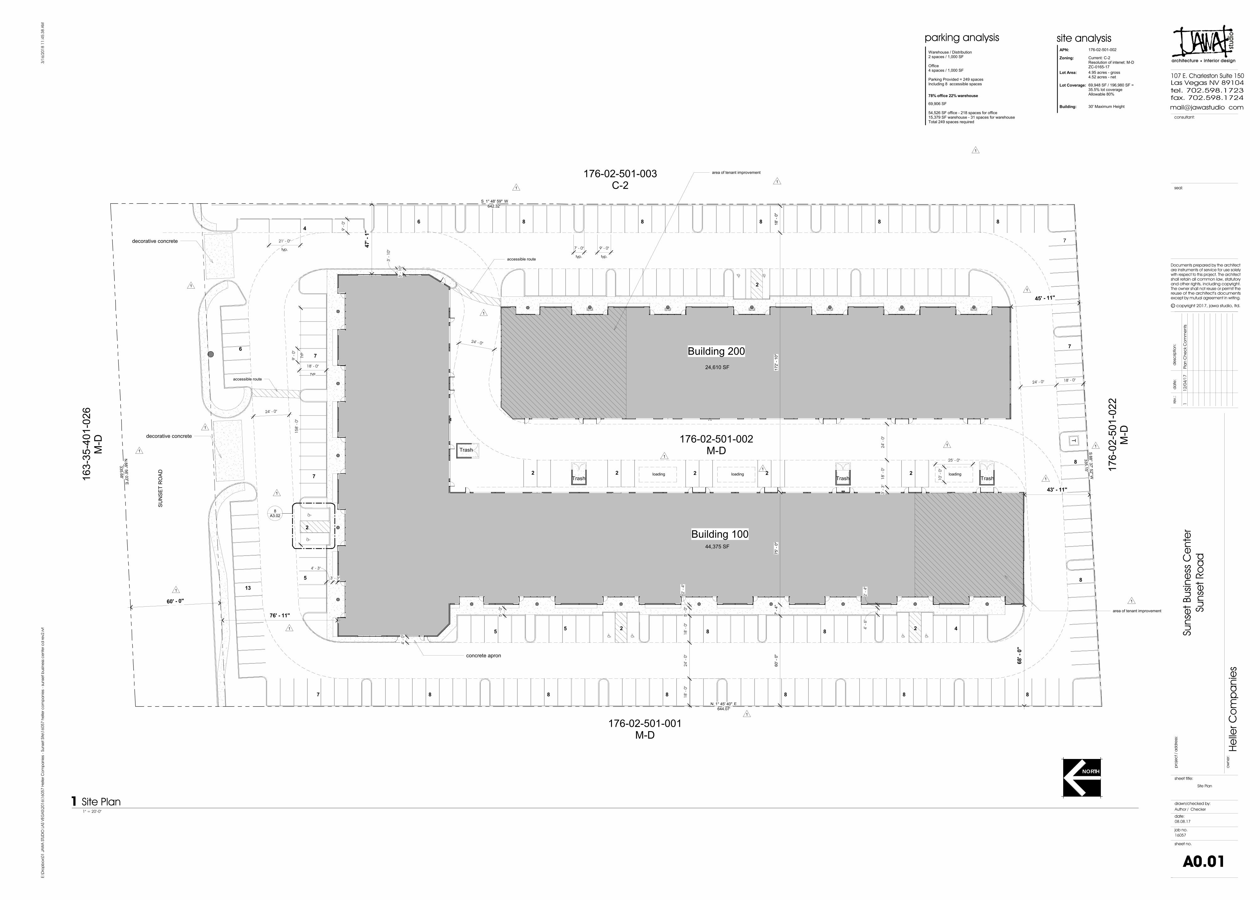
site analysis
APN: 176-02-501-002
Lot Area: 4.95 acres - gross4.52 acres - net
Lot Coverage: 69,948 SF / 196,980 SF = 35.5% lot coverageAllowable 80%
parking analysis
Warehouse / Distribution2 spaces / 1,000 SF
Office4 spaces / 1,000 SF
Parking Provided = 249 spacesIncluding 8 accessible spaces
Building: 30' Maximum Height
Zoning: Current: C-2 Resolution of intenet: M-DZC-0165-17
78% office 22% warehouse
69,906 SF
54,526 SF office - 218 spaces for office15,379 SF warehouse - 31 spaces for warehouseTotal 249 spaces required
sheet title:
sheet no.
drawn/checked by:
job no.
date:
ow
ne
r:
pro
jec
t / a
dd
re
ss:
tel. 702.598.1723
fax. 702.598.1724
mail@jawastudio com
107 E. Charleston Suite 150
Las Vegas NV 89104
re
v.:
da
te
:d
esc
rip
tio
n:
and other rights, including copyright.
copyright 2017, jawa studio, ltd.
reuse of the architect's documents
except by mutual agreement in writing.
The owner shall not reuse or permit the
Documents prepared by the architect
are instruments of service for use solely
with respect to this project. The architect
shall retain all common law, statutory
Oc
seal:
consultant:
3/1
6/2
01
8 1
1:4
5:3
8 A
ME:\D
ro
pb
ox\0
1 JA
WA
STU
DIO
LA
S V
EG
AS\2
01
6\1
60
57
H
elle
r C
om
pa
nie
s - Su
nse
t Site
\1
60
57
h
elle
r c
om
pa
nie
s - su
nse
t b
usin
ess c
en
te
r c
d re
v2
.rvt
He
lle
r C
om
pa
nie
s
Su
nse
t Bu
sin
ess C
en
te
r
Su
nse
t R
oa
d
08.08.17
16057
Site Plan
Author / Checker
A0.01
1" = 20'-0"
1 Site Plan
NORTH
1
1
11
2/0
4/1
7Pla
n C
he
ck C
om
me
nts

sheet title:
sheet no.
drawn/checked by:
job no.
date:
ow
ne
r:
pro
jec
t / a
dd
re
ss:
tel. 702.598.1723
fax. 702.598.1724
mail@jawastudio com
107 E. Charleston Suite 150
Las Vegas NV 89104
re
v.:
da
te
:d
esc
rip
tio
n:
and other rights, including copyright.
copyright 2017, jawa studio, ltd.
reuse of the architect's documents
except by mutual agreement in writing.
The owner shall not reuse or permit the
Documents prepared by the architect
are instruments of service for use solely
with respect to this project. The architect
shall retain all common law, statutory
Oc
seal:
consultant:
3/1
6/2
01
8 1
1:4
5:4
6 A
ME:\D
ro
pb
ox\0
1 JA
WA
STU
DIO
LA
S V
EG
AS\2
01
6\1
60
57
H
elle
r C
om
pa
nie
s - Su
nse
t Site
\1
60
57
h
elle
r c
om
pa
nie
s - su
nse
t b
usin
ess c
en
te
r c
d re
v2
.rvt
He
lle
r C
om
pa
nie
s
Su
nse
t Bu
sin
ess C
en
te
r
Su
nse
t R
oa
d
08.08.17
16057
IECC Energy Compliance
Author / Checker
A0.02
Sheet added 1
11
2/0
4/1
7Pla
n C
he
ck C
om
me
nts

ALIG
N
24
1' - 4
"
A
B
C
D
E
F
F
GG
HH
JJ
KK
LL
12
12
16
16
17
17
18
18
36' - 10"36' - 10"
24
' - 0
"2
4' - 0
"2
4' - 0
"2
4' - 0
"2
4' - 0
"2
4' - 0
"2
4' - 0
"2
4' - 0
"2
4' - 0
"2
4' - 0
"
24' - 0"24' - 0"24' - 0"24' - 0"24' - 0"24' - 0"24' - 0"24' - 0"24' - 0"24' - 0"28' - 0"28' - 0"28' - 0"28' - 0"30' - 8"36' - 10"36' - 10"
A.8
C.2
D.8
75
' - 0
"
36
' - 1
0"
36
' - 1
0"
1
A2.01
Electrical
75' - 0"
4
A2.01
5
A2.01
6
A2.01
3
A2.01
13
13
14
14
15
15
F.R.
2
2
3
3
4
4
5
5
6
6
7
7
8
8
9
9
10
10
11
11
2
A2.01
1
1
21
' - 4
"
24
1' - 4
"
A3.024
A3.023 A3.02
1
A3.011
12' - 9" 16' - 0" 8' - 1" 4' - 7" 15' - 10" 16' - 5"
12
' - 9
"1
2' - 9
"1
6' - 0
"1
6' - 0
"
12' - 9" 16' - 0" 12' - 0" 18' - 3"
location of future phase restrooms - typ.
BA
C
E
C
A A
A4.013
4A5.02
4A5.02
3A5.02
3A5.02
1A5.02
1A5.02
5' - 0
"
2' - 11"
3' - 6"
8' - 0" 8' - 0"
3' - 6"
30
' - 0
"
12
' - 6
"5
' - 0
"
12' - 0"
19
' - 5
"
22' - 0" 22' - 0"
SK-11
A7.012
A3.025
A3.02 6
7
knox box
DD
type 1 entry
note: store front entries for gridlines A.8 and 18 are typical type 1unless noted otherwisesee 1/A3.01
area of tenant improvement
A0.005
2A5.02
2A5.02
102
100
104
106
108
110
112
114
116
118
120 122 124
126 128
130 132 134 136 138 140 142 144 146 148
5A5.01
5A5.01
type 2 typical demising wall
6A5.01
6A5.01
1
1
1
1
1
1
1
1
1
1
1
1 1 11 1 1
1 1 1
11 1
1
1
1
A3.012
22' - 0"
22
' - 0
"
7' - 8
"
7
A2.01
SK-41
16' - 0" 3' - 6"
sheet title:
sheet no.
drawn/checked by:
job no.
date:
ow
ne
r:
pro
jec
t / a
dd
re
ss:
tel. 702.598.1723
fax. 702.598.1724
mail@jawastudio com
107 E. Charleston Suite 150
Las Vegas NV 89104
re
v.:
da
te
:d
esc
rip
tio
n:
and other rights, including copyright.
copyright 2017, jawa studio, ltd.
reuse of the architect's documents
except by mutual agreement in writing.
The owner shall not reuse or permit the
Documents prepared by the architect
are instruments of service for use solely
with respect to this project. The architect
shall retain all common law, statutory
Oc
seal:
consultant:
3/1
6/2
01
8 1
1:4
5:5
2 A
ME:\D
ro
pb
ox\0
1 JA
WA
STU
DIO
LA
S V
EG
AS\2
01
6\1
60
57
H
elle
r C
om
pa
nie
s - Su
nse
t Site
\1
60
57
h
elle
r c
om
pa
nie
s - su
nse
t b
usin
ess c
en
te
r c
d re
v2
.rvt
He
lle
r C
om
pa
nie
s
Su
nse
t Bu
sin
ess C
en
te
r
Su
nse
t R
oa
d
08.08.17
16057
Building 100 Floor Plan
Author / Checker
A1.01
1/16" = 1'-0"
1 First Floor Plan - Building 100
NORTH
1
11
2/0
4/1
7Pla
n C
he
ck C
om
me
nts
23
/1
2/1
8Bu
ild
ing
C
oo
rd
ina
tio
n

A A
B B
C C
36
' - 1
0"
36
' - 1
0"
F.R.
Electrical
73
' - 8
"
2
A2.02
1
A2.02 3
A2.02
4
A2.02
A3.014
3A5.03
3A5.03
shear wallA3.024
note: store front entries for gridline C are typical type 1unless noted otherwisesee 1/A3.01
A7.01
6
----
----
200 202 204
206 208 210 212 214 216 218 220 222 224
2A5.03
2A5.03
1A5.03
1A5.03
4A5.03
4A5.03
1
1
1
11 1 1 1 1 1 1 1 1
25
' - 0
"
1
1
2
2
3
3
4
4
5
5
6
6
7
7
8
8
9
9
10
10
11
11
12
12
13
13
15
15
34' - 8" 24' - 0" 24' - 0" 28' - 0" 28' - 0" 28' - 0" 28' - 0" 24' - 0" 24' - 0" 24' - 0" 24' - 0" 24' - 0" 24' - 0"
F
E
FDD
A3.013
22
' - 0
"
knox box
1
1
9' - 4" 16' - 0" 3' - 6"5' - 10"
sheet title:
sheet no.
drawn/checked by:
job no.
date:
ow
ne
r:
pro
jec
t / a
dd
re
ss:
tel. 702.598.1723
fax. 702.598.1724
mail@jawastudio com
107 E. Charleston Suite 150
Las Vegas NV 89104
re
v.:
da
te
:d
esc
rip
tio
n:
and other rights, including copyright.
copyright 2017, jawa studio, ltd.
reuse of the architect's documents
except by mutual agreement in writing.
The owner shall not reuse or permit the
Documents prepared by the architect
are instruments of service for use solely
with respect to this project. The architect
shall retain all common law, statutory
Oc
seal:
consultant:
3/1
6/2
01
8 1
1:4
5:5
4 A
ME:\D
ro
pb
ox\0
1 JA
WA
STU
DIO
LA
S V
EG
AS\2
01
6\1
60
57
H
elle
r C
om
pa
nie
s - Su
nse
t Site
\1
60
57
h
elle
r c
om
pa
nie
s - su
nse
t b
usin
ess c
en
te
r c
d re
v2
.rvt
He
lle
r C
om
pa
nie
s
Su
nse
t Bu
sin
ess C
en
te
r
Su
nse
t R
oa
d
08.08.17
16057
Building 200 Floor Plan
Author / Checker
A1.02
1/16" = 1'-0"
1 First Floor Plan - Building 200
NORTH
11
2/0
4/1
7Pla
n C
he
ck C
om
me
nts

A
B
C
D
E
FF
GG
HH
JJ
KK
LL
12
12
16
16
17
17
18
18
A.8
C.2
D.8
4
A2.01
5
A2.01
6
A2.01
3
A2.01
13
13
14
14
15
15
2
2
3
3
4
4
5
5
6
6
7
7
8
8
9
9
10
10
11
11
2
A2.01
1
1
4A5.02
3A5.02
3A5.02
1A5.02
1A5.02
2A5.02
2A5.02
5A5.01
5A5.01
108' - 0"
6A5.01
7A5.01
108' - 0"
1
1
2
2
3
3
4
4
5
5
6
6
7
7
8
8
9
9
10
10
11
11
12
12
13
13
15
15
7
A2.01
sheet title:
sheet no.
drawn/checked by:
job no.
date:
ow
ne
r:
pro
jec
t / a
dd
re
ss:
tel. 702.598.1723
fax. 702.598.1724
mail@jawastudio com
107 E. Charleston Suite 150
Las Vegas NV 89104
re
v.:
da
te
:d
esc
rip
tio
n:
and other rights, including copyright.
copyright 2017, jawa studio, ltd.
reuse of the architect's documents
except by mutual agreement in writing.
The owner shall not reuse or permit the
Documents prepared by the architect
are instruments of service for use solely
with respect to this project. The architect
shall retain all common law, statutory
Oc
seal:
consultant:
3/1
6/2
01
8 1
1:4
5:5
8 A
ME:\D
ro
pb
ox\0
1 JA
WA
STU
DIO
LA
S V
EG
AS\2
01
6\1
60
57
H
elle
r C
om
pa
nie
s - Su
nse
t Site
\1
60
57
h
elle
r c
om
pa
nie
s - su
nse
t b
usin
ess c
en
te
r c
d re
v2
.rvt
He
lle
r C
om
pa
nie
s
Su
nse
t Bu
sin
ess C
en
te
r
Su
nse
t R
oa
d
08.08.17
16057
Building 100 Ceiling Plan
Author / Checker
A1.03
1/16" = 1'-0"
1 Building 100 Ceiling Plan
NORTH

A A
B B
C C
4
A2.02
3A5.03
3A5.03
A7.01 1
2A5.03
1A5.03
4A5.03
4A5.03
1
1
2
2
3
3
4
4
5
5
6
6
7
7
8
8
9
9
10
10
11
11
12
12
13
13
15
15
sheet title:
sheet no.
drawn/checked by:
job no.
date:
ow
ne
r:
pro
jec
t / a
dd
re
ss:
tel. 702.598.1723
fax. 702.598.1724
mail@jawastudio com
107 E. Charleston Suite 150
Las Vegas NV 89104
re
v.:
da
te
:d
esc
rip
tio
n:
and other rights, including copyright.
copyright 2017, jawa studio, ltd.
reuse of the architect's documents
except by mutual agreement in writing.
The owner shall not reuse or permit the
Documents prepared by the architect
are instruments of service for use solely
with respect to this project. The architect
shall retain all common law, statutory
Oc
seal:
consultant:
3/1
6/2
01
8 1
1:4
5:5
9 A
ME:\D
ro
pb
ox\0
1 JA
WA
STU
DIO
LA
S V
EG
AS\2
01
6\1
60
57
H
elle
r C
om
pa
nie
s - Su
nse
t Site
\1
60
57
h
elle
r c
om
pa
nie
s - su
nse
t b
usin
ess c
en
te
r c
d re
v2
.rvt
He
lle
r C
om
pa
nie
s
Su
nse
t Bu
sin
ess C
en
te
r
Su
nse
t R
oa
d
08.08.17
16057
Building 200 Ceiling Plan
Author / Checker
A1.04
1/16" = 1'-0"
1 Building 200 Ceiling Plan
NORTH

A
B
C
D
E
FF
GG
HH
JJ
KK
LL
12
12
16
16
17
17
18
18
A.8
C.2
D.8
4
A2.01
5
A2.01
6
A2.01
3
A2.01
13
13
14
14
15
15
2
2
3
3
4
4
5
5
6
6
7
7
8
8
9
9
10
10
11
11
2
A2.01
1
1
A2.031
4A5.02
4A5.02
min1/4" / Ft. min
1/4" / Ft.
1/4"
/ Ft
.
1/4" / Ft.
1/4" / Ft.
min
1/4"
/ Ft
.
3A5.02
3A5.02
1A5.02
1A5.02
min1/4" / Ft.
min1/4" / Ft.
min1/4" / Ft.
min1/4" / Ft.
min1/4" / Ft.
min1/4" / Ft.
min1/4" / Ft.
min1/4" / Ft.
min1/4" / Ft.
min1/4" / Ft.
min1/4" / Ft.
min1/4" / Ft.
min1/4" / Ft.
min
1/4"
/ Ft
.m
in1/
4" /
Ft.
min
1/4"
/ Ft
.m
in1/
4" /
Ft.
min
1/4"
/ Ft
.m
in1/
4" /
Ft.
min
1/4"
/ Ft
.m
in1/
4" /
Ft.
1/4"
/ Ft
.
min
1/4"
/ Ft
.
30' - 0" 28' - 0"
typical ACper MEP
typical evaporative cooler typical skylight with curb
123' - 8"
121' - 8"
EvaporativeCooler
4' x 8' skylights on curbTYP
ACCurb
Typical
1
1
1
2A5.02
2A5.02
120' - 8"
120' - 8"
120' - 8"
121' - 8"
120' - 8"
121' - 8"
120' - 8"
121' - 8"
122' - 2 1/2"121' - 8"
121' - 8"
122' - 2"
121' - 8"
121' - 8"
121' - 8" 123' - 8"122' - 8" 122' - 8" 123' - 8" 122' - 8" 123' - 8" 122' - 8" 123' - 8" 122' - 8" 123' - 8" 122' - 8" 123' - 8"
124' - 6"
123' - 8"
16
' - 0
"
32
' - 0
"2
0' - 0
"
20' - 0" 32' - 0"
16' - 0"
5A5.01
----
6A5.01
7A5.01
7
A2.01
122' - 8"
1
1
1
1
1
1
111
1 11
1
typical AC pad
typical swamp cooler pad
1
1
1
1
1
T.O.P 126' - 0"
T.O.P 127' - 6"
T.O.P 125' - 0"
T.O.P 126' - 0"
T.O.P 125' - 0"
T.O.P 123' - 0"
T.O.P 125' - 6"
T.O.P 125' - 6"
T.O.P 125' - 6"
T.O.P 125' - 6"
T.O.P 125' - 6" T.O.P 125' - 6"
T.O.P 125' - 6"
T.O.P 127' - 6"
T.O.P 126' - 0"
1
TYP
8' - 0"
TYP
4' - 0
"
123' - 8" 123' - 8" 123' - 8" 123' - 8" 123' - 8" 123' - 8"
124' - 6" 124' - 6" 124' - 6"124' - 6"124' - 6"
121' - 8"
121' - 8"
121' - 8"
122' - 6"
122' - 6"
122' - 6"
122' - 6"
122' - 6"
122' - 6"
123' - 8"
124' - 6"
22
1
2
2
2
2
2
2
2
22
22
2
2
2
2
2
2
2
2
2
2
2 2 2 2 2 2 2 2 2 2 2 2 2 2
2
124' - 6"
124' - 6"
123' - 8"
122' - 8"
2
2
123' - 8"2
sheet title:
sheet no.
drawn/checked by:
job no.
date:
ow
ne
r:
pro
jec
t / a
dd
re
ss:
tel. 702.598.1723
fax. 702.598.1724
mail@jawastudio com
107 E. Charleston Suite 150
Las Vegas NV 89104
re
v.:
da
te
:d
esc
rip
tio
n:
and other rights, including copyright.
copyright 2017, jawa studio, ltd.
reuse of the architect's documents
except by mutual agreement in writing.
The owner shall not reuse or permit the
Documents prepared by the architect
are instruments of service for use solely
with respect to this project. The architect
shall retain all common law, statutory
Oc
seal:
consultant:
3/1
6/2
01
8 1
1:4
6:0
5 A
ME:\D
ro
pb
ox\0
1 JA
WA
STU
DIO
LA
S V
EG
AS\2
01
6\1
60
57
H
elle
r C
om
pa
nie
s - Su
nse
t Site
\1
60
57
h
elle
r c
om
pa
nie
s - su
nse
t b
usin
ess c
en
te
r c
d re
v2
.rvt
He
lle
r C
om
pa
nie
s
Su
nse
t Bu
sin
ess C
en
te
r
Su
nse
t R
oa
d
08.08.17
16057
Building 100 Roof Plan
Author / Checker
A1.05
1/16" = 1'-0"
1 Building 100 Roof Plan NORTH
11
2/0
4/1
7Pla
n C
he
ck C
om
me
nts
23
/1
2/1
8Bu
ild
ing
C
oo
rd
ina
tio
n

A A
B B
C C
2
A2.02
1
A2.02 3
A2.02
4
A2.02
3A5.03
3A5.03
min
1/4"
/ Ft
.
min
1/4"
/ Ft
.
min
1/4"
/ Ft
.
----2
A5.031
A5.03
4A5.03
4A5.03
typical skylight with curb
1
1
2
2
3
3
4
4
5
5
6
6
7
7
8
8
9
9
10
10
11
11
12
12
13
13
15
15
min1/4" / Ft.
min1/4" / Ft.
min1/4" / Ft.
min1/4" / Ft.
min1/4" / Ft.
min1/4" / Ft.
min1/4" / Ft.
min1/4" / Ft.
min1/4" / Ft.
min1/4" / Ft.
min1/4" / Ft.
min1/4" / Ft.
min1/4" / Ft.
126' - 2" 127' - 2" 126' - 2" 127' - 2" 126' - 2" 127' - 2" 126' - 2" 127' - 2" 126' - 2" 127' - 2" 126' - 2" 127' - 2" 126' - 2" 127' - 2"
127' - 2"127' - 2"127' - 2"127' - 2"
1 11 1 1
1
11
1 11 1 1
1
111
1
1
1 11
1 1 1
typical AC curbrefer to MEP for sizing
typical swamp cooler padrefer to MEP for sizing
1
1
TYP
8' - 0"
TYP
4' - 0
"
1
128' - 0"
128' - 0"128' - 0" 128' - 0"
128' - 0"128' - 0"
127' - 2"
2
22
2 2
2222
222
2222222
127' - 2"2
127' - 2"2 127' - 2"
2
sheet title:
sheet no.
drawn/checked by:
job no.
date:
ow
ne
r:
pro
jec
t / a
dd
re
ss:
tel. 702.598.1723
fax. 702.598.1724
mail@jawastudio com
107 E. Charleston Suite 150
Las Vegas NV 89104
re
v.:
da
te
:d
esc
rip
tio
n:
and other rights, including copyright.
copyright 2017, jawa studio, ltd.
reuse of the architect's documents
except by mutual agreement in writing.
The owner shall not reuse or permit the
Documents prepared by the architect
are instruments of service for use solely
with respect to this project. The architect
shall retain all common law, statutory
Oc
seal:
consultant:
3/1
6/2
01
8 1
1:4
6:0
6 A
ME:\D
ro
pb
ox\0
1 JA
WA
STU
DIO
LA
S V
EG
AS\2
01
6\1
60
57
H
elle
r C
om
pa
nie
s - Su
nse
t Site
\1
60
57
h
elle
r c
om
pa
nie
s - su
nse
t b
usin
ess c
en
te
r c
d re
v2
.rvt
He
lle
r C
om
pa
nie
s
Su
nse
t Bu
sin
ess C
en
te
r
Su
nse
t R
oa
d
08.08.17
16057
Building 200 Roof Plan
Author / Checker
A1.06
1/16" = 1'-0"
1 Building 200 Roof Plan
typical AC
NORTH
11
2/0
4/1
7Pla
n C
he
ck C
om
me
nts
23
/1
2/1
8Bu
ild
ing
C
oo
rd
ina
tio
n

First Floor100' - 0"
glass storefront entry
tilt up concrete panels - paint finish
concrete column with reveals
concrete panel joint - typ.
reveal with accent paint color
100 HI Parapet N/S125' - 6"
First Floor100' - 0"
100 HI Parapet E/W127' - 6"
reveal with accent paint color
tilt up concrete panels - paint finish
glass storefront system
6A5.01
First Floor100' - 0"
14
' - 0
"25
' - 0
"
rollup doors
tilt up concrete panels - paint finish
hollow metal door - paint finishschlage hardware TYP
concrete panel joint - typ.
23
' - 0
"
100 HI Parapet N/S125' - 6"
100 Lo Parapet N/S123' - 0"
First Floor100' - 0"
100 Lo Parapet E/W125' - 0"
rollup doors
tilt up concrete panels - paint finish
hollow metal door - paint finish
concrete panel joint - typ.
4A5.02
hollow metal door - paint finishschlage hardware TYP
127' - 6"
127' - 6"
1
11
per foot1/2 % slope
1
First Floor100' - 0"
reveal with accent paint color
tilt up concrete panels - paint finish
glass storefront system2
5' - 6
"
125' - 6"
100 HI Parapet N/S125' - 6"
123' - 0"
1
First Floor100' - 0"
100 HI Parapet E/W127' - 6"
glass storefront entry
tilt up concrete panels - paint finish
concrete column with reveals
concrete panel joint - typ.
reveal with accent paint color4A5.02
5A5.01
125' - 6"
1
per foot1/2 % slope
First Floor100' - 0"
125' - 6"
100 HI Parapet N/S125' - 6"
sheet title:
sheet no.
drawn/checked by:
job no.
date:
ow
ne
r:
pro
jec
t / a
dd
re
ss:
tel. 702.598.1723
fax. 702.598.1724
mail@jawastudio com
107 E. Charleston Suite 150
Las Vegas NV 89104
re
v.:
da
te
:d
esc
rip
tio
n:
and other rights, including copyright.
copyright 2017, jawa studio, ltd.
reuse of the architect's documents
except by mutual agreement in writing.
The owner shall not reuse or permit the
Documents prepared by the architect
are instruments of service for use solely
with respect to this project. The architect
shall retain all common law, statutory
Oc
seal:
consultant:
3/1
6/2
01
8 1
1:4
6:1
4 A
ME:\D
ro
pb
ox\0
1 JA
WA
STU
DIO
LA
S V
EG
AS\2
01
6\1
60
57
H
elle
r C
om
pa
nie
s - Su
nse
t Site
\1
60
57
h
elle
r c
om
pa
nie
s - su
nse
t b
usin
ess c
en
te
r c
d re
v2
.rvt
He
lle
r C
om
pa
nie
s
Su
nse
t Bu
sin
ess C
en
te
r
Su
nse
t R
oa
d
08.08.17
16057
Building 100 Exterior Elevations
Author / Checker
A2.01
1/16" = 1'-0"
1 Building 100 North
1/16" = 1'-0"
3 Building 100 South 1
1/16" = 1'-0"
5 Building 100 South 2
1/16" = 1'-0"
4 Building 100 East 1
1/16" = 1'-0"
6 Building 100 East 2
1/16" = 1'-0"
2 Building 100 West
1/16" = 1'-0"
7 South Corner Elevation
1
11
2/0
4/1
7Pla
n C
he
ck C
om
me
nts

T ectonic Cop yright 2007
First Floor100' - 0"
200 Parapet130' - 0"
reveal with accent paint color
tilt up concrete panels - paint finish
glass storefront system
----
2A5.03
First Floor100' - 0"
200 Parapet130' - 0"
rollup doors
tilt up concrete panels - paint finish
hollow metal door - paint finish
concrete panel joint - typ.A2.03
23A5.03
4A5.03
on panels1/2 % slope
panel openings and joints are to be vertical
First Floor100' - 0"
200 Parapet130' - 0"
reveal with accent paint color
tilt up concrete panels - paint finish
glass storefront system
----1
A5.03
First Floor100' - 0"
200 Parapet130' - 0"
glass storefront entry
tilt up concrete panels - paint finish
concrete column with reveals
concrete panel joint - typ.
reveal with accent paint color
3A5.03
4A5.03
on panels1/2 % slope
panel opening and joints are to be vertical
30
' - 0
"
sheet title:
sheet no.
drawn/checked by:
job no.
date:
ow
ne
r:
pro
jec
t / a
dd
re
ss:
tel. 702.598.1723
fax. 702.598.1724
mail@jawastudio com
107 E. Charleston Suite 150
Las Vegas NV 89104
re
v.:
da
te
:d
esc
rip
tio
n:
and other rights, including copyright.
copyright 2017, jawa studio, ltd.
reuse of the architect's documents
except by mutual agreement in writing.
The owner shall not reuse or permit the
Documents prepared by the architect
are instruments of service for use solely
with respect to this project. The architect
shall retain all common law, statutory
Oc
seal:
consultant:
3/1
6/2
01
8 1
1:4
6:2
0 A
ME:\D
ro
pb
ox\0
1 JA
WA
STU
DIO
LA
S V
EG
AS\2
01
6\1
60
57
H
elle
r C
om
pa
nie
s - Su
nse
t Site
\1
60
57
h
elle
r c
om
pa
nie
s - su
nse
t b
usin
ess c
en
te
r c
d re
v2
.rvt
He
lle
r C
om
pa
nie
s
Su
nse
t Bu
sin
ess C
en
te
r
Su
nse
t R
oa
d
08.08.17
16057
Building 200 Exterior Elevations
Author / Checker
A2.02
1/16" = 1'-0"
1 Building 200 North
1/16" = 1'-0"
2 Building 200 West
1/16" = 1'-0"
3 Building 200 South
1/16" = 1'-0"
4 Building 200 East
1
1
11
2/0
4/1
7Pla
n C
he
ck C
om
me
nts

T
T T T
T
T
T
tempered glass
metal panel over metal stud construction
concrete tilt-up panel
6"
4"
3/4" wide 3/4" deep bands typ
Va
rie
s
4' - 6
"
6"
1
A4.01
2
A4.01
T
3' - 0
"
8' - 2
"
6"
6"
12
' - 4
"
16
' - 0
"
8' - 2
"
12
' - 4
"
6"
5 1
/4
"
1hollow metal doorschlage hardware typ.
overhead roll up door typ.
concrete tilt-up panel typ.
metal protected corner typ at roll up door
7
A4.01
4' - 0
"
chamfered reveal
sheet title:
sheet no.
drawn/checked by:
job no.
date:
ow
ne
r:
pro
jec
t / a
dd
re
ss:
tel. 702.598.1723
fax. 702.598.1724
mail@jawastudio com
107 E. Charleston Suite 150
Las Vegas NV 89104
re
v.:
da
te
:d
esc
rip
tio
n:
and other rights, including copyright.
copyright 2017, jawa studio, ltd.
reuse of the architect's documents
except by mutual agreement in writing.
The owner shall not reuse or permit the
Documents prepared by the architect
are instruments of service for use solely
with respect to this project. The architect
shall retain all common law, statutory
Oc
seal:
consultant:
3/1
6/2
01
8 1
1:4
6:2
1 A
ME:\D
ro
pb
ox\0
1 JA
WA
STU
DIO
LA
S V
EG
AS\2
01
6\1
60
57
H
elle
r C
om
pa
nie
s - Su
nse
t Site
\1
60
57
h
elle
r c
om
pa
nie
s - su
nse
t b
usin
ess c
en
te
r c
d re
v2
.rvt
He
lle
r C
om
pa
nie
s
Su
nse
t Bu
sin
ess C
en
te
r
Su
nse
t R
oa
d
08.08.17
16057
Building 100 Enlarged Elevations
Author / Checker
A2.03
1/4" = 1'-0"
1 Typical Bay Elevation
1/4" = 1'-0"
2 Typical Garage Elevation
Sheet Added
1
11
2/0
4/1
7Pla
n C
he
ck C
om
me
nts

A.8 A.8
34
5
5
EQEQEQEQ
5' - 0
"
line of tilt-up panel above
typ. 2' dia cast in place concrete column
4 1/2" wide anodized aluminum storefront door and window system w/ vertical butt glazing typ.
24' - 0" 24' - 0"
8' - 0" 4' - 0" 24' - 0" 4' - 0" 8' - 0"
x3'
-0"
8' -0
"
x3'
-0"
8' -0
"
G
D
H
VIF
D
G
3 steel columns per structuralcenter on mullion1
1
1
1
1
4A5.02
Sim
blue tinted glass on outboard paneclear on inboard pane all glass temperedU-Value .48 SHGC .62 Projection Factor is .36
1
A
concrete tilt-up panel
hollow metal door
over head roll up door
A4.013
A4.017
A4.017 sim
2 3
8' - 8" 6' - 0" 3' - 8" 5' - 8"
2' - 0" 4' - 0"
24' - 0"
12' - 0" 3' - 4"2' - 8"
A3.02 6
7
A7.018
Typical
Office
Typical
Office
Typical
Office
Typical
Office
Typical
Toilet
Typical
Toilet
Typical
Warehouse
Typical
Warehouse
Typical
Reception
Typical
Reception
styrostud furring with R-6 closed cell strofom wall on concrete panel in conditioned spaces
10' h wall partion type 1
full height partition type 2
future toilet buildout
x3'
-0"
7' -0
"
x3'
-0"
7' -0
"
x3'
-0"
7' -0
"
x3'
-0"
8' -0
"
x3'
-0"
8' -0
"
x3'
-0"
8' -0
"x
3' -0
"7'
-0"
x3'
-0"
7' -0
"
x3' - 0" 7' - 0"x3' - 0" 7' - 0"
x3' - 0" 7' - 0"
x3' - 0" 7' - 0"x3' - 0" 7' - 0"
x3' - 0" 7' - 0"
storefront system
center partion on mullioncenter partion on mullion
center partion on reveal
14
' - 0
"
22
' - 0
"
11' - 5"
CLR
7' - 8"
R-15 insulation between office and adjacent suite
CLR
7' - 8
"
R-19 between office and warehouse including all bathroom partitions
R-38 above lay-in ceiling
A7.01
6
Typical
Warehouse
Typical
Office
Typical
Office
Typical
Reception
Typical
Toilet
Typical
Toilet
Typical
Office
Typical
Office
Typical
Warehouse
Typical
Reception
styrostud wall on concrete panel in conditioned spaces
full heighttype 2 partion
10' type 1 partions
x3'
-0"
7' -0
"
x3' - 0" 7' - 0"
x3' - 0" 7' - 0"x3' - 0" 7' - 0"
x3' - 0" 7' - 0"
x3' - 0" 7' - 0" x3' - 0" 7' - 0"
x3'
-0"
7' -0
"
x3'
-0"
8' -0
"
x3'
-0"
8' -0
"
storefront system
frameless storefront door
rollup metal door factory painted
hollow metal door painted
x3'
-0"
7' -0
"
x3'
-0"
7' -0
"
x3'
-0"
7' -0
"
x3'
-0"
8' -0
"
center on reveal
center on mullion
R-19 in all bathroom partions
R-19 between office and warehouse
R-19 between office and warehouse
styrostud furring with R-6 closed cell strofom wall on concrete panel in
conditioned spaces
R-15 insulation between office and adjacent space
1
1
1
1
1
sheet title:
sheet no.
drawn/checked by:
job no.
date:
ow
ne
r:
pro
jec
t / a
dd
re
ss:
tel. 702.598.1723
fax. 702.598.1724
mail@jawastudio com
107 E. Charleston Suite 150
Las Vegas NV 89104
re
v.:
da
te
:d
esc
rip
tio
n:
and other rights, including copyright.
copyright 2017, jawa studio, ltd.
reuse of the architect's documents
except by mutual agreement in writing.
The owner shall not reuse or permit the
Documents prepared by the architect
are instruments of service for use solely
with respect to this project. The architect
shall retain all common law, statutory
Oc
seal:
consultant:
3/1
6/2
01
8 1
1:4
6:2
3 A
ME:\D
ro
pb
ox\0
1 JA
WA
STU
DIO
LA
S V
EG
AS\2
01
6\1
60
57
H
elle
r C
om
pa
nie
s - Su
nse
t Site
\1
60
57
h
elle
r c
om
pa
nie
s - su
nse
t b
usin
ess c
en
te
r c
d re
v2
.rvt
He
lle
r C
om
pa
nie
s
Su
nse
t Bu
sin
ess C
en
te
r
Su
nse
t R
oa
d
08.08.17
16057
Enlarged Floor Plans
Author / Checker
A3.01
1/4" = 1'-0"
1 First Floor - Building 100 - Typical Type 1 Entry
1/4" = 1'-0"
4 Typical Overhead Door Layout
1/8" = 1'-0"
2 Unit- Building 100 - Typical Buildout
1/8" = 1'-0"
3 Unit - Building 200 - Typical Buildout11
1
1
1
11
2/0
4/1
7Pla
n C
he
ck C
om
me
nts

10
' - 0
"
10' - 0"
6"concrete curb
tilt up concrete panel
5' - 0
"
apron
First Floor100' - 0"
2" sq tubing
3/4" sq pickets
6' - 0
"
backing 1/8" steel plate
12
12
D.8 D.8
10' - 8"
12' - 0"
metal stud partition
hollow metal door
concrete tilt-up panel
Electrical
19
' - 5
"4
' - 4
"
1' - 0"
x3'
-0"
7' -0
"
x3' - 0" 7' - 0" x3' - 0" 7' - 0"
concrete tilt-up panel
1' - 0
"
D.8 D.8
14
14
8' - 0"
4' - 8
"
F.R.
1 hour rated metal stud partion type 3
concrete tilt-up panel
6' - 8"
19' - 0"
hollow metal doorschlage hardware TYP
4' - 4
"4
' - 4
"
concrete tilt-up panel
x3' - 0" 7' - 0"
x3'
-0"
7' -0
"
1' - 0"
13
' - 4
"
4' - 0"
4aA3.02
1
knox box typical1
ø 60"
A3.02 6
7C
LR
7' - 8
"
4"
CLR
7' - 8"
16"-18"
17"-1
9"
max34"
33"-3
6"
12" min
min
36"
min
18"
min
18"
min
1 1/
2"
min
24"
max
42"
33"-3
6"
39"-4
1"
min
18"
max
12" 42" min
39"-41"
8' - 0
"
20' - 0"
8' - 0
"
First Floor100' - 0"
D.8
A4.031
1 hour rated
A4.032
concrete tilt-up panel wall
knox box
opening
sheet title:
sheet no.
drawn/checked by:
job no.
date:
ow
ne
r:
pro
jec
t / a
dd
re
ss:
tel. 702.598.1723
fax. 702.598.1724
mail@jawastudio com
107 E. Charleston Suite 150
Las Vegas NV 89104
re
v.:
da
te
:d
esc
rip
tio
n:
and other rights, including copyright.
copyright 2017, jawa studio, ltd.
reuse of the architect's documents
except by mutual agreement in writing.
The owner shall not reuse or permit the
Documents prepared by the architect
are instruments of service for use solely
with respect to this project. The architect
shall retain all common law, statutory
Oc
seal:
consultant:
3/1
6/2
01
8 1
1:4
6:2
5 A
ME:\D
ro
pb
ox\0
1 JA
WA
STU
DIO
LA
S V
EG
AS\2
01
6\1
60
57
H
elle
r C
om
pa
nie
s - Su
nse
t Site
\1
60
57
h
elle
r c
om
pa
nie
s - su
nse
t b
usin
ess c
en
te
r c
d re
v2
.rvt
He
lle
r C
om
pa
nie
s
Su
nse
t Bu
sin
ess C
en
te
r
Su
nse
t R
oa
d
08.08.17
16057
Enlarged Floor Plans
Author / Checker
A3.02
1/2" = 1'-0"
1 Trash Enclosure Plan
1/2" = 1'-0"
2 Typical Trash Enclosure
1/4" = 1'-0"
3 Typical -Electrical Room
1/4" = 1'-0"
4 Typical- Fire Riser Room
1/2" = 1'-0"
5 Typical Bathroom
1/2" = 1'-0"
6 Bathroom 1
1/2" = 1'-0"
7 Bathroom 2
1/4" = 1'-0"
8 Typical ADA
1/4" = 1'-0"
4aFire Riser Room Section
1
1
1
11
2/0
4/1
7Pla
n C
he
ck C
om
me
nts

A.8
3/4"
3/4
"3
/4
"
6"
4 1
/2
"
typical concrete tilt-up panel
reveal
A.8
3/4
"3
/4
"
2 1
/2
"
4"
3/4"
typ concrete tilt-up panel
reveal
3/4"
3/8" 3/8"
3/4"
3/4
"
sealant and backer rod
24" X 24" piece ofDynaflex
deck flange secured to deck
mbr flashing cement, mbr utility cement,or hot asphalt
roof deck
strainer basket
gravel stop flange and sleeve
sealant furnished with drain
flashing clamping ring
flexible neoprene bellows body
taper to provide sump drain
2"
overflow drain
WALL
continuous bead of sealant
fastener 12" max oc
notes:1. flashing must be cut at inside and inside corners. do not bend around corners.2. flashing must be fastened within 1" max. of all section ends.3. bonding adhesive required between roofing and substrate for fully adhered systems.
built up roofing
sheet metal flashing
cast gap
substrate
1/2"
cant strip support
3 ply w/ 90# cap sheet(2) 40# plys
1
tilt up exterior wall
opening at roll up door
1/4" metal plate cast corner protector
sim: opposite hand
2 1/2"
2 1
/2
"
1
cant
roofing build up
flashing
2x 10 curb
4 x 6 supports
open
refer to structural for additional information
sheet title:
sheet no.
drawn/checked by:
job no.
date:
ow
ne
r:
pro
jec
t / a
dd
re
ss:
tel. 702.598.1723
fax. 702.598.1724
mail@jawastudio com
107 E. Charleston Suite 150
Las Vegas NV 89104
re
v.:
da
te
:d
esc
rip
tio
n:
and other rights, including copyright.
copyright 2017, jawa studio, ltd.
reuse of the architect's documents
except by mutual agreement in writing.
The owner shall not reuse or permit the
Documents prepared by the architect
are instruments of service for use solely
with respect to this project. The architect
shall retain all common law, statutory
Oc
seal:
consultant:
3/1
6/2
01
8 1
1:4
6:2
6 A
ME:\D
ro
pb
ox\0
1 JA
WA
STU
DIO
LA
S V
EG
AS\2
01
6\1
60
57
H
elle
r C
om
pa
nie
s - Su
nse
t Site
\1
60
57
h
elle
r c
om
pa
nie
s - su
nse
t b
usin
ess c
en
te
r c
d re
v2
.rvt
He
lle
r C
om
pa
nie
s
Su
nse
t Bu
sin
ess C
en
te
r
Su
nse
t R
oa
d
08.08.17
16057
Typical Details
Author / Checker
A4.01
3" = 1'-0"
1 Reveal
3" = 1'-0"
2 Top Reveal
1 1/2" = 1'-0"
3 Panel Chamfer
3" = 1'-0"
5 Roof Drain Typical
1 1/2" = 1'-0"
6 Roofing to Wall
1 1/2" = 1'-0"
7 Corner Protector
1 1/2" = 1'-0"
4 Roof Curb
11
2/0
4/1
7Pla
n C
he
ck C
om
me
nts

4'-0
" m
in. - 6
'-0
" m
ax.
4'-0" min. - 6'-0" max.
Plan View
interior non-load bearing partial height partition - refer to partition types
25 ga. 3 5/8" metal stud brace - fasten each end with (3) #8 sheet metal screws
45 degmax.
45 deg
max.
compression post detail compression post detail (alt)
steel stud compression post at 12'-0" oc. each way max
cross tee
12 ga. brace wires
main tee
steel tube compression post at 12'-0" oc. each way max
main teecross tee
compression stud to be 25 guage min.
1 5/8" stud - max length 6'-2"
2 1/2" stud - max length 10'-6"
compression tube to be emt conduit
1/2" dia. emt - max length 6'- 0"
3/4"dia. emt - max length 8'-6"
1" dia. emt - max length 10'-0"
suspended lay-in or gyp bd ceiling isometric
12 ga. hanger wire at 48" oc. each way - plumb within 1 in 6
main tee
cross tee
lay-in ceiling tile or gyp bd.
12 ga. perimeter hanger wire at 8"max from wall
perimeter wall angle - pop rivet tees to wall on two adjacent walls
1. all wires to have 3 tight turns within 3" of connection.
2. provide lateral bracing at 12'-0" oc. each way. refer to compression post detail for specific requirements.
3. light fixtures and mechanical devices weighing not more than 56 lbs. are to have two 12 ga. wires to the structure above.
4. lay-in ceiling system will comply with ASTM C 635 & ASTM C 636, ASCE 7-05 and CISCA requirements.
5. drywall grid system will comply with ASTM C 635 & ASTM & ASTM C 636, ASCE 7-05 ASTM C 754 and CISCA requirements.
1. all wires to have 3 tight turns within 3" of connection
2. compression posts to be located 12'-0" oc. max in both directions and no farther that 6'-0" from the perimeter wall
1. all wires to have 3 tight turns within 3" of connection
2. compression posts to be located 12'-0" oc. max in both directions and no farther that 6'-0" from the perimeter wall
Top of Slab
Wall base as scheduled
continuous 20 ga bottom track fastened to slab with 0.157" powder actuated fasteners at 32" O.C. Min. 1" embed
(1) layer 5/8" gypsum wall board each side of wall (full height) attached with min. 1" type "S" drywall screws at 16" O.C. min.
Full height metal studs - at 16" o.c.
Line of finished ceiling
Underside of Structure Above
Non-rated, non-load bearing interior metal stud partition, full height to underside of structure above. Provide sound attenutation batt where indicated on floor plans. (STC rating: 45)
Partition Type 2
Top of Slab
Wall base as scheduled
continuous 20 ga bottom track fastened to slab with 0.157" powder actuated fasteners at 32" O.C. Min. 1" embed
(1) layer 5/8" gypsum wall board each side of wall (full height) attached with min. 1" type "S" drywall screws at 16" O.C. min.
Full height metal studs - minimum 3 5/8" 20 gauge at 24" o.c.
Line of finished ceiling
Underside of Structure Above
Non-rated, non-load bearing interior metal stud partition, partial height to underside of ceiling. Provide sound attenutation batt where indicated on floor plans. (STC rating: 45)
Partition Type 3
25 ga. 3 5/8" metal studs at 4'-0" o.c., alternating directions. attach each end with (2) #8 sheet metal screws
Refer to alternate partition brace detail for optional bracing installation
Top of Slab
Wall base as scheduled
continuous 20 ga bottom track fastened to slab with 0.157" powder actuated fasteners at 32" O.C. Min. 1" embed
(1) layer 5/8" gypsum wall board each side of wall (full height) attached with min. 1" type "S" drywall screws at 16" O.C. min.
Full height metal studs - refer to span tables for required stud gauge and spacing
Line of finished ceiling
Underside of Structure Above
Non-rated, non-load bearing interior metal stud partition, partial height to 6" above heighest adjacent ceiling. Provide sound attenutation batt where indicated on floor plans. (STC rating: 45)
Min
.
6"
Partition Type 1
25 ga. 3 5/8" metal studs at 4'-0" o.c., alternating directions. attach each end with (2) #8 sheet metal screws
Refer to alternate partition brace detail for optional bracing installation
1/2
"
1 # 8 screw per stud typical connectioneach flange stud to steel track top and bottom
1 # 8 screw per stud typical connectioneach flange stud to steel track top and bottom
1 # 8 screw per stud typical connectioneach flange stud to steel track top and bottom
composite wall sheathed both sides full height with gypsum wall board per chapter 25 of 2012 IBCstuds braced by gypsum wall board each side5 psf max lateral loadFy(min) = 33KSIL/120 deflection limitfor height > 18'-0" and bracing >8'-0", submit engineering design and details.
General Notes:
Note: 1 hour fire rated wall per IBC 2012 table 721.1(2) 13-1.311
Metal Stud Height Chart
(25 GAUGE)
(22 GAUGE)
(20 GAUGE)
sheet title:
sheet no.
drawn/checked by:
job no.
date:
ow
ne
r:
pro
jec
t / a
dd
re
ss:
tel. 702.598.1723
fax. 702.598.1724
mail@jawastudio com
107 E. Charleston Suite 150
Las Vegas NV 89104
re
v.:
da
te
:d
esc
rip
tio
n:
and other rights, including copyright.
copyright 2017, jawa studio, ltd.
reuse of the architect's documents
except by mutual agreement in writing.
The owner shall not reuse or permit the
Documents prepared by the architect
are instruments of service for use solely
with respect to this project. The architect
shall retain all common law, statutory
Oc
seal:
consultant:
3/1
6/2
01
8 1
1:4
6:3
0 A
ME:\D
ro
pb
ox\0
1 JA
WA
STU
DIO
LA
S V
EG
AS\2
01
6\1
60
57
H
elle
r C
om
pa
nie
s - Su
nse
t Site
\1
60
57
h
elle
r c
om
pa
nie
s - su
nse
t b
usin
ess c
en
te
r c
d re
v2
.rvt
He
lle
r C
om
pa
nie
s
Su
nse
t Bu
sin
ess C
en
te
r
Su
nse
t R
oa
d
08.08.17
16057
Typical Details
RM / JW
A4.023/4" = 1'-0"
2 Alternate Partition Brace1
3" = 1'-0"
3 Typical Ceiling Details1
1 1/2" = 1'-0"
1 Partition Types1
11
2/0
4/1
7Pla
n C
he
ck C
om
me
nts

concrete tilt up panel
fire caulking
fire caulking
1 hour fire rated wall per IBC 2012 table 721.1(2) 13-1.3
5/8" gyp bd
5/8" gyp bd
25 ga. metal stud
3/4" plywood
fire caulking
fire caulking
5/8" gyp bd
25 ga. metal stud per plan
1 hour rated type 3 wall
one hour rated assembly 5/8" gyp bd
3/4" plywood
flat metal panelcontinuous caulk joint
metal channelexterior sheathing
channel closure with 4" end lapsweather barriermetal stud5/8" gyp bd
1/2
"
flat panel metalmetal channel
concrete panel
powder actuated shot pin per structural
metal stud
exterior sheathing
weather barrier
sealant with backer rod
caulking
concrete panel
shim as necessary 5/8" gyp bd
store front by manufacturer
sealant with backer rod
shim as necessary
5/8" gyp bd
store front by manufacturer
concrete panel
powder actuated shot pin per structural
sealant with backer rod
2x4 metal stud
shim as necessary
5/8" gyp bd
store front by manufacturer
weather barrier
batt insulation exterior sheathing
metal panel
concrete screw/ wood screw
adjustment bolt
sealant with backer rod
storefront system
foundation
sheet title:
sheet no.
drawn/checked by:
job no.
date:
ow
ne
r:
pro
jec
t / a
dd
re
ss:
tel. 702.598.1723
fax. 702.598.1724
mail@jawastudio com
107 E. Charleston Suite 150
Las Vegas NV 89104
re
v.:
da
te
:d
esc
rip
tio
n:
and other rights, including copyright.
copyright 2017, jawa studio, ltd.
reuse of the architect's documents
except by mutual agreement in writing.
The owner shall not reuse or permit the
Documents prepared by the architect
are instruments of service for use solely
with respect to this project. The architect
shall retain all common law, statutory
Oc
seal:
consultant:
3/1
6/2
01
8 1
1:4
6:3
1 A
ME:\D
ro
pb
ox\0
1 JA
WA
STU
DIO
LA
S V
EG
AS\2
01
6\1
60
57
H
elle
r C
om
pa
nie
s - Su
nse
t Site
\1
60
57
h
elle
r c
om
pa
nie
s - su
nse
t b
usin
ess c
en
te
r c
d re
v2
.rvt
He
lle
r C
om
pa
nie
s
Su
nse
t Bu
sin
ess C
en
te
r
Su
nse
t R
oa
d
08.08.17
16057
Details
Author / Checker
A4.03
1 1/2" = 1'-0"
1 Fire Riser Ceiling at Concrete
1 1/2" = 1'-0"
2 Fire Riser Ceiling at Stud
1 1/2" = 1'-0"
3 Metal Panel Soffit to Wall
1 1/2" = 1'-0"
4 Metal Panel Soffit to Concrete Panel
1 1/2" = 1'-0"
5 Store Front Jamb Typical
1 1/2" = 1'-0"
6 Store Front Head at Concrete Panel
1 1/2" = 1'-0"
7 Store Front Head at Metal Stud
1 1/2" = 1'-0"
8 Store Front Sill
sheet added
1
1
1 1
11
1
1
11
2/0
4/1
7Pla
n C
he
ck C
om
me
nts

First Floor100' - 0"
100 HI Parapet E/W127' - 6"
ABCDEFGHJKL A.8C.2D.83A5.02
1A5.02
2A5.02
----7
A5.01
100 HI Parapet N/S125' - 6"
100 Lo Parapet N/S123' - 0"
1
First Floor100' - 0"
100 HI Parapet E/W127' - 6"
2 3 4 5 6 7 81
type 2 partitionstype 1 partion
First Floor100' - 0"
100 HI Parapet E/W127' - 6"
12 1613 14 158 9 10 114
A5.02
3' - 0
"
1
sheet title:
sheet no.
drawn/checked by:
job no.
date:
ow
ne
r:
pro
jec
t / a
dd
re
ss:
tel. 702.598.1723
fax. 702.598.1724
mail@jawastudio com
107 E. Charleston Suite 150
Las Vegas NV 89104
re
v.:
da
te
:d
esc
rip
tio
n:
and other rights, including copyright.
copyright 2017, jawa studio, ltd.
reuse of the architect's documents
except by mutual agreement in writing.
The owner shall not reuse or permit the
Documents prepared by the architect
are instruments of service for use solely
with respect to this project. The architect
shall retain all common law, statutory
Oc
seal:
consultant:
3/1
6/2
01
8 1
1:4
6:3
3 A
ME:\D
ro
pb
ox\0
1 JA
WA
STU
DIO
LA
S V
EG
AS\2
01
6\1
60
57
H
elle
r C
om
pa
nie
s - Su
nse
t Site
\1
60
57
h
elle
r c
om
pa
nie
s - su
nse
t b
usin
ess c
en
te
r c
d re
v2
.rvt
He
lle
r C
om
pa
nie
s
Su
nse
t Bu
sin
ess C
en
te
r
Su
nse
t R
oa
d
08.08.17
16057
Building 100 - Sections
Author / Checker
A5.01
1/8" = 1'-0"
5 Building 100 Longitudinal N/S
1/8" = 1'-0"
6 Building 100 Longitudinal E/W - left
1/8" = 1'-0"
7 Building 100 Longitudinal E/W - right
11
2/0
4/1
7Pla
n C
he
ck C
om
me
nts

T ectonic Cop yright 2007
First Floor100' - 0"
100 HI Parapet E/W127' - 6"
16 17 18
ledger per structural A4.014
A6.013
skylight
evaporative cooleropening per structural
AC opening per structural
5A5.01
100 HI Parapet N/S125' - 6"
1
1
126' - 0"
1
First Floor100' - 0"
16 17 18
100 Lo Parapet E/W125' - 0"
5A5.01
rollup warehouse door
23
' - 0
"
100 Lo Parapet N/S123' - 0"
First Floor100' - 0"
16 17 18
A4.014A4.01
6A6.01
1skylight
evaporative cooler
AC
100 HI Parapet N/S125' - 6"
100 Lo Parapet N/S123' - 0"
1
First Floor100' - 0"
100 HI Parapet E/W127' - 6"
A.8C.2D.8
100 Lo Parapet E/W125' - 0"
A4.014
A4.015
A6.012
skylight
evaporative coolerAC
----7
A5.01
SK-32
1
sheet title:
sheet no.
drawn/checked by:
job no.
date:
ow
ne
r:
pro
jec
t / a
dd
re
ss:
tel. 702.598.1723
fax. 702.598.1724
mail@jawastudio com
107 E. Charleston Suite 150
Las Vegas NV 89104
re
v.:
da
te
:d
esc
rip
tio
n:
and other rights, including copyright.
copyright 2017, jawa studio, ltd.
reuse of the architect's documents
except by mutual agreement in writing.
The owner shall not reuse or permit the
Documents prepared by the architect
are instruments of service for use solely
with respect to this project. The architect
shall retain all common law, statutory
Oc
seal:
consultant:
3/1
6/2
01
8 1
1:4
6:3
4 A
ME:\D
ro
pb
ox\0
1 JA
WA
STU
DIO
LA
S V
EG
AS\2
01
6\1
60
57
H
elle
r C
om
pa
nie
s - Su
nse
t Site
\1
60
57
h
elle
r c
om
pa
nie
s - su
nse
t b
usin
ess c
en
te
r c
d re
v2
.rvt
He
lle
r C
om
pa
nie
s
Su
nse
t Bu
sin
ess C
en
te
r
Su
nse
t R
oa
d
08.08.17
16057
Building 100 - Sections
Author / Checker
A5.02
1/8" = 1'-0"
1 Building 100 Section 2
1/8" = 1'-0"
2 Building 100 Section Through Panel
1/8" = 1'-0"
3 Building 100 Section Through Store Front
1/8" = 1'-0"
4 Building 100 Section 3
Sheet Added
1
11
2/0
4/1
7Pla
n C
he
ck C
om
me
nts

First Floor100' - 0"
200 Parapet130' - 0"
1 2 3 4 5 6 7
A4.015
A4.015
A4.015
First Floor100' - 0"
200 Parapet130' - 0"
3A5.03
4A5.03
8 9 10 11 12 13 15
A4.015
A4.015
A4.015
A4.015
built out suitetype 1 partition
130' - 0"
130' - 0"
127' - 2"
126' - 8 1/2"
1
First Floor100' - 0"
A B C
200 Parapet130' - 0"
----2
A5.03
25' -
0"
23
' - 2
3
/4
"
ACCurb
TypicalEvaporative
Cooler
skylight
concrete tilt-up panel
column per structural
type 3 partition
concrete tilt-up panel
130' - 0"
130' - 0"
127' - 2"
126' - 2"
future bathroom
1
1
First Floor100' - 0"
A B C
200 Parapet130' - 0"
----2
A5.03
concrete tilt-up panel wall1 hour rated ceiling
1 hour rated partition
A4.015
skylight ACCurb
Typical
EvaporativeCooler
future restroom
130' - 0"
126' - 2"
130' - 0"
127' - 2"
knox box1
1
1
128' - 0"
sheet title:
sheet no.
drawn/checked by:
job no.
date:
ow
ne
r:
pro
jec
t / a
dd
re
ss:
tel. 702.598.1723
fax. 702.598.1724
mail@jawastudio com
107 E. Charleston Suite 150
Las Vegas NV 89104
re
v.:
da
te
:d
esc
rip
tio
n:
and other rights, including copyright.
copyright 2017, jawa studio, ltd.
reuse of the architect's documents
except by mutual agreement in writing.
The owner shall not reuse or permit the
Documents prepared by the architect
are instruments of service for use solely
with respect to this project. The architect
shall retain all common law, statutory
Oc
seal:
consultant:
3/1
6/2
01
8 1
1:4
6:3
6 A
ME:\D
ro
pb
ox\0
1 JA
WA
STU
DIO
LA
S V
EG
AS\2
01
6\1
60
57
H
elle
r C
om
pa
nie
s - Su
nse
t Site
\1
60
57
h
elle
r c
om
pa
nie
s - su
nse
t b
usin
ess c
en
te
r c
d re
v2
.rvt
He
lle
r C
om
pa
nie
s
Su
nse
t Bu
sin
ess C
en
te
r
Su
nse
t R
oa
d
08.08.17
16057
Building 200 - Sections
Author / Checker
A5.03
1/8" = 1'-0"
1 Building 200 Longitudinal E/W - left
1/8" = 1'-0"
2 Building 200 Longitudinal E/W - right
1/8" = 1'-0"
3 Building 200 Section Through Electrical
1/8" = 1'-0"
4 Building 200 Section Through FR
Sheet Added
1
1
1
11
2/0
4/1
7Pla
n C
he
ck C
om
me
nts

First Floor100' - 0"
17
column footing see structural
built up roof
2 x wood nailer on steel roof joists 96" OC see structural
R-19 white scrim facing
steel beam see structural
steel column see structural
EvaporativeCooler
100 Lo Parapet N/S123' - 0"
First Floor100' - 0"
100 HI Parapet E/W127' - 6"
B A.8
built up roof
A4.016
opposite hand
2x wood nailer over steel roof joist 96" OC seet structural
ledger and fastener per structural
concrete tilt up exterior wall panel see structural exterior elevations TYP.
R-19 insulation white scrim facing
vent or reveal
anodized aluminum storefront system
metal panel over weather barrier over exterior sheathing
2x framing
cast in place concrete column
4" concrete walk
column footing see structural
expansion joint
6" slab over prepared base and subgrade see structural
bracing per structural
A4.033
A4.034
1
1 steel column per structural
steel header per structural1
R-19 in vertical partiion
R-38 on top of exterior soffit
Styro Stud with R-6 closed cell Styrofoam
blue tinted glass on outboard paneclear on inboard pane all glass temperedU-Value .48 SHGC .62 Projection Factor is .36
1
1
1
First Floor100' - 0"
100 HI Parapet E/W127' - 6"
16
built up roofing
A4.016
ledger and fasteners per structural
steel joist per structural
R-19 insulation white scrim facing
2 x nailer over joists
steel joist 96" OC see structural
concrete slab
126' - 0"
sheet title:
sheet no.
drawn/checked by:
job no.
date:
ow
ne
r:
pro
jec
t / a
dd
re
ss:
tel. 702.598.1723
fax. 702.598.1724
mail@jawastudio com
107 E. Charleston Suite 150
Las Vegas NV 89104
re
v.:
da
te
:d
esc
rip
tio
n:
and other rights, including copyright.
copyright 2017, jawa studio, ltd.
reuse of the architect's documents
except by mutual agreement in writing.
The owner shall not reuse or permit the
Documents prepared by the architect
are instruments of service for use solely
with respect to this project. The architect
shall retain all common law, statutory
Oc
seal:
consultant:
3/1
6/2
01
8 1
1:4
6:3
7 A
ME:\D
ro
pb
ox\0
1 JA
WA
STU
DIO
LA
S V
EG
AS\2
01
6\1
60
57
H
elle
r C
om
pa
nie
s - Su
nse
t Site
\1
60
57
h
elle
r c
om
pa
nie
s - su
nse
t b
usin
ess c
en
te
r c
d re
v2
.rvt
He
lle
r C
om
pa
nie
s
Su
nse
t Bu
sin
ess C
en
te
r
Su
nse
t R
oa
d
08.08.17
16057
Building 100 - Wall Sections
Author / Checker
A6.01
1/4" = 1'-0"
1 Wall Section at Column
1/4" = 1'-0"
2 Wall Section TYP
1/4" = 1'-0"
3 Central Wall Section
Sheet Added
1
11
2/0
4/1
7Pla
n C
he
ck C
om
me
nts

TT T T
8' - 2
"
16' - 0"
EQ EQ EQ EQ
T T T
T
9' - 0
"
8' - 0
"
T T T
T T T
T T T
T T T
T
3' - 6"
8' - 2
"
T
5' - 0"
8' - 2
"
T
VIF
16' - 0"
EQEQEQ 3' - 0"
8' - 2
"
TT T T
T8
' - 2
"
3' - 6"4' - 0"
8' - 2
"
T
VIF
24' - 0"
8' - 2
"
EQEQEQEQ3' - 0" 3' - 0"
T T T TTT
sheet title:
sheet no.
drawn/checked by:
job no.
date:
ow
ne
r:
pro
jec
t / a
dd
re
ss:
tel. 702.598.1723
fax. 702.598.1724
mail@jawastudio com
107 E. Charleston Suite 150
Las Vegas NV 89104
re
v.:
da
te
:d
esc
rip
tio
n:
and other rights, including copyright.
copyright 2017, jawa studio, ltd.
reuse of the architect's documents
except by mutual agreement in writing.
The owner shall not reuse or permit the
Documents prepared by the architect
are instruments of service for use solely
with respect to this project. The architect
shall retain all common law, statutory
Oc
seal:
consultant:
3/1
6/2
01
8 1
1:4
6:3
8 A
ME:\D
ro
pb
ox\0
1 JA
WA
STU
DIO
LA
S V
EG
AS\2
01
6\1
60
57
H
elle
r C
om
pa
nie
s - Su
nse
t Site
\1
60
57
h
elle
r c
om
pa
nie
s - su
nse
t b
usin
ess c
en
te
r c
d re
v2
.rvt
He
lle
r C
om
pa
nie
s
Su
nse
t Bu
sin
ess C
en
te
r
Su
nse
t R
oa
d
08.08.17
16057
Store Fronts
Author / Checker
A7.01
1/2" = 1'-0"
1 Store Front A
1/2" = 1'-0"
2 Store Front B
1/2" = 1'-0"
3 Store Front C
1/2" = 1'-0"
4 Store Front D
1/2" = 1'-0"
5 Store Front E
1/2" = 1'-0"
6 Store Front F
1/2" = 1'-0"
7 Store Front G
1/2" = 1'-0"
8 Store Front H
Sheet Added
1
1 1 1
11 1
1
11
2/0
4/1
7Pla
n C
he
ck C
om
me
nts