eding cnc manual · eding cnc manual 09 november 2018 release 4.03 4 acknowledgements the g-code...
TRANSCRIPT
EDING CNC Manual
09 November 2018 Release 4.03 1
User Manual Eding CNC Software
Document Release 4.03
EDING CNC Manual
09 November 2018 Release 4.03 2
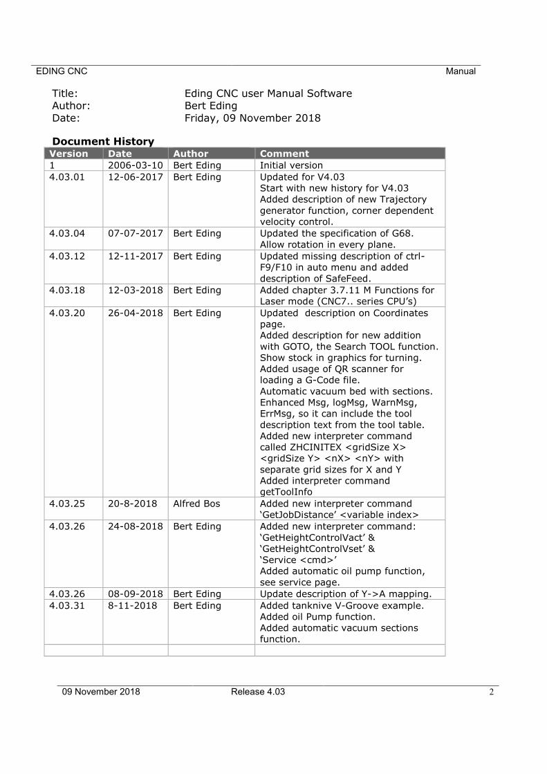
Title: Eding CNC user Manual Software Author: Bert Eding
Date: Friday, 09 November 2018
Document History
Version Date Author Comment
1 2006-03-10 Bert Eding Initial version
4.03.01 12-06-2017 Bert Eding Updated for V4.03
Start with new history for V4.03
Added description of new Trajectory
generator function, corner dependent
velocity control.
4.03.04 07-07-2017 Bert Eding Updated the specification of G68.
Allow rotation in every plane.
4.03.12 12-11-2017 Bert Eding Updated missing description of ctrl-
F9/F10 in auto menu and added
description of SafeFeed.
4.03.18 12-03-2018 Bert Eding Added chapter 3.7.11 M Functions for
Laser mode (CNC7.. series CPU’s)
4.03.20 26-04-2018 Bert Eding Updated description on Coordinates
page.
Added description for new addition
with GOTO, the Search TOOL function.
Show stock in graphics for turning.
Added usage of QR scanner for
loading a G-Code file.
Automatic vacuum bed with sections.
Enhanced Msg, logMsg, WarnMsg,
ErrMsg, so it can include the tool
description text from the tool table.
Added new interpreter command
called ZHCINITEX <gridSize X>
<gridSize Y> <nX> <nY> with
separate grid sizes for X and Y
Added interpreter command
getToolInfo
4.03.25 20-8-2018 Alfred Bos Added new interpreter command
‘GetJobDistance’ <variable index>
4.03.26 24-08-2018 Bert Eding Added new interpreter command:
‘GetHeightControlVact’ &
‘GetHeightControlVset’ &
‘Service <cmd>’
Added automatic oil pump function,
see service page.
4.03.26 08-09-2018 Bert Eding Update description of Y->A mapping.
4.03.31 8-11-2018 Bert Eding Added tanknive V-Groove example.
Added oil Pump function.
Added automatic vacuum sections
function.

EDING CNC Manual
09 November 2018 Release 4.03 3
© Copyright Eding CNC Holding B.V. All rights reserved. Reproduction in whole or in part prohibited without the prior written
consent of the copyright owner.

EDING CNC Manual
09 November 2018 Release 4.03 4
ACKNOWLEDGEMENTS
The G-Code part of this user manual has been derived from the full report of the RS274/NGC language. Parts that are less relevant to Eding
CNC users or parts that are not supported are left out.

EDING CNC Manual
09 November 2018 Release 4.03 5
Table of contents
Table of contents .................................................................................................................................. 5
1 Introduction ................................................................................................................................... 10
1.1 Context and scope ....................................................................................................... 11
1.2 Definitions, acronyms and abbreviations ...................................................................... 12
1.3 Minimum PC requirements ........................................................................................... 13
1.4 Installation of EDINGCNC ............................................................................................. 14 1.4.1 USB ............................................................................................................................................... 14 1.4.2 Ethernet ....................................................................................................................................... 16 1.4.3 Set admin mode and switch off UAC ........................................................................................... 20 1.4.4 Disable automatic update in Windows 10 ................................................................................... 22 1.4.5 Connected drives not visible Windows 10 ................................................................................... 24 1.4.6 Profiles, If you have different setups e.g. lathe and milling......................................................... 25
2 The user interface ....................................................................................................................... 27
2.1.1 Setup Pages .................................................................................................................................. 31 2.1.2 UI and Connection ....................................................................................................................... 31 2.1.3 Motor setup ................................................................................................................................. 32 2.1.4 Homing and ESTOP setup ............................................................................................................ 34 2.1.5 Backlash setup ............................................................................................................................. 35 2.1.6 LAF setup...................................................................................................................................... 36 2.1.7 Kinematic Setup ........................................................................................................................... 39 2.1.8 Tool change Area setup ............................................................................................................... 39 2.1.9 Tangential knife setup.................................................................................................................. 39 2.1.10 Safety/Door open Input setup ..................................................................................................... 43 2.1.11 Spindle and PWM setup ............................................................................................................... 43 2.1.12 UI setup items .............................................................................................................................. 46 2.1.13 IO setup ........................................................................................................................................ 47 2.1.14 Interpreter settings ...................................................................................................................... 48 2.1.15 Traffic light setup ......................................................................................................................... 48 2.1.16 JobTimeEstimation ....................................................................................................................... 49 2.1.17 Hand wheel Setup ........................................................................................................................ 49 2.1.18 Load/Run Automatically .............................................................................................................. 50 2.1.19 Probing Setup ............................................................................................................................... 52 2.1.20 Camera Setup ............................................................................................................................... 53 2.1.21 CPUOPT ........................................................................................................................................ 54 2.1.22 Using a safety relay ...................................................................................................................... 55
2.1.22.1 Powering the safety relay .................................................................................................... 55 2.1.22.2 Input contacts of the safety relay ........................................................................................ 55 2.1.22.3 Output contacts of the safety relais..................................................................................... 56 2.1.22.4 Switching on the safety relay ............................................................................................... 56
2.1.23 Operate Page, this is where the machine is operated ................................................................. 58 2.1.24 Operate page introduction .......................................................................................................... 58 2.1.25 Reset Button F1............................................................................................................................ 60 2.1.26 Escape Button .............................................................................................................................. 60 2.1.27 The menus ................................................................................................................................... 60
2.1.27.1 Main Menu ........................................................................................................................... 60 2.1.27.2 Home menu ......................................................................................................................... 60 2.1.27.3 Zero menu ............................................................................................................................ 61
EDING CNC Manual
09 November 2018 Release 4.03 6
2.1.27.4 Auto menu ........................................................................................................................... 61 2.1.27.5 IO menu ............................................................................................................................... 67 2.1.27.6 Graphic menu....................................................................................................................... 67 2.1.27.7 Jog menu .............................................................................................................................. 68 2.1.27.8 Jog pad ................................................................................................................................. 68 2.1.27.9 User menu ............................................................................................................................ 69
2.1.28 Operate page tasks ...................................................................................................................... 70 2.1.28.1 Startup ................................................................................................................................. 70 2.1.28.2 Homing ................................................................................................................................. 70 2.1.28.3 Load and run a g-code file .................................................................................................... 70
2.1.29 Coordinate Page Tasks ................................................................................................................. 75 2.1.29.1 Calibrate/Activate coordinate systems ................................................................................ 75 2.1.29.2 Mapping X/Y G-code to cylinder on A-Axis .......................................................................... 76 2.1.29.3 Milling un-even surfaces ...................................................................................................... 78
2.2 Linear PITCH compensation .......................................................................................... 83
2.3 XY Non rectangular Cross compensation ....................................................................... 84
2.4 Speed-PWM compensation .......................................................................................... 85
2.5 Automatic vacuum sections.......................................................................................... 87
2.6 Program Page, DXF and HPGL import ........................................................................... 88
2.7 Tools Page ................................................................................................................... 91 2.7.1 Milling .......................................................................................................................................... 91 2.7.2 Turning ......................................................................................................................................... 92 2.7.3 Tool change .................................................................................................................................. 92 2.7.4 Automatic user defined Tool change ATC .................................................................................... 92 2.7.5 Changing the tool number without actual tool change ............................................................... 93 2.7.6 The variable Page ......................................................................................................................... 93
2.8 IO Page ....................................................................................................................... 95
2.9 Service Page ................................................................................................................ 96
2.10 Util Page, Chipload and Feed/Speed ......................................................................... 98
2.11 homing and coordinate systems ................................................................................ 99 2.11.1 Manual homing the machine ..................................................................................................... 100 2.11.2 Automatic homing the machine and HomeIsEstop ................................................................... 101 2.11.3 Tandem axes homing ................................................................................................................. 102 2.11.4 Work versus Machine coordinate system and zeroing .............................................................. 104
2.12 3D Printing ............................................................................................................. 105
2.13 Keyboard shortcuts................................................................................................. 108
2.14 Zero tool macro ...................................................................................................... 110
2.15 Tool measurement Macro ....................................................................................... 111
3 Input: the RS274/NGC Language ......................................................................................................... 115
3.1 System-Parameters/Variables .................................................................................... 116
3.2 Tool data ................................................................................................................... 120 3.2.1.1 Tool Orientation for lathes .................................................................................................... 120
3.3 Coordinate Systems ................................................................................................... 121
3.4 Format of a Line ......................................................................................................... 122 3.4.1 Line Number .............................................................................................................................. 122
EDING CNC Manual
09 November 2018 Release 4.03 7
3.4.2 Word .......................................................................................................................................... 122 3.4.2.1 Number .................................................................................................................................. 123 3.4.2.2 Parameter Value .................................................................................................................... 123 3.4.2.3 Expressions and Binary Operations........................................................................................ 124 3.4.2.4 Unary Operation Value .......................................................................................................... 124
3.4.3 Parameter Setting ...................................................................................................................... 125 3.4.4 Comments and Messages .......................................................................................................... 125 3.4.5 Item Repeats .............................................................................................................................. 125 3.4.6 Item order .................................................................................................................................. 126 3.4.7 Commands and Machine Modes ............................................................................................... 126
3.5 Modal Groups ............................................................................................................ 127
3.6 G Codes ..................................................................................................................... 129 3.6.1 Rapid Linear Motion - G0 ........................................................................................................... 129 3.6.2 Linear Motion at Feed Rate - G1 ................................................................................................ 131 3.6.3 Arc at Feed Rate - G2 and G3 ..................................................................................................... 132
3.6.3.1 Radius Format Arc .................................................................................................................. 132 3.6.3.2 Center Format Arc .................................................................................................................. 133
3.6.4 Dwell - G4 ................................................................................................................................... 134 3.6.5 Set Coordinate System Data -G10 .............................................................................................. 134 3.6.6 Plane Selection - G17, G18, and G19 ......................................................................................... 134 3.6.7 Length Units - G20/G21 and G70/G71 ....................................................................................... 134 3.6.8 Return to Home - G28 and G30 ................................................................................................. 135 3.6.9 G33, G33.1 Spindle-Synchronized Motion ................................................................................. 136 3.6.10 Straight Probe - G38.2 ................................................................................................................ 137
3.6.10.1 The Straight Probe Command ............................................................................................ 137 3.6.10.2 Using the Straight Probe Command................................................................................... 137 3.6.10.3 Example Code .................................................................................................................... 138
3.6.11 Cutter Radius Compensation - G40, G41, G41.1, G42, G42.1 .................................................... 139 3.6.11.1 Example code for milling .................................................................................................... 140 3.6.11.2 Example code for turning ................................................................................................... 141
3.6.12 Tool Length Offsets - G43, G43 H, G43.1, and G49 ................................................................... 143 3.6.13 Scaling G50/G51 ......................................................................................................................... 143 3.6.14 Move in Absolute Coordinates - G53 ......................................................................................... 144 3.6.15 Select Coordinate System - G54 to G59.3 .................................................................................. 144 3.6.16 Path Control Mode and Look ahead feed- G61, and G64 .......................................................... 145 3.6.17 Coordinate system rotation G68 ................................................................................................ 151 3.6.18 Threading (Lathe) – G76 ............................................................................................................ 151 3.6.19 Cancel Modal Motion - G80 ....................................................................................................... 154 3.6.20 Canned Cycles - G81 to G89 ....................................................................................................... 154
3.6.20.1 Preliminary and In-Between Motion.................................................................................. 155 3.6.20.2 G81 Cycle ........................................................................................................................... 156 3.6.20.3 G82 Cycle ........................................................................................................................... 157 3.6.20.4 G83 Cycle ........................................................................................................................... 157 3.6.20.5 G73 Cycle ........................................................................................................................... 157 3.6.20.6 G84 Cycle ........................................................................................................................... 158 3.6.20.7 G74 Cycle ........................................................................................................................... 158 3.6.20.8 G85 Cycle ........................................................................................................................... 158 3.6.20.9 G86 Cycle ........................................................................................................................... 158 3.6.20.10 G87 Cycle ........................................................................................................................... 159 3.6.20.11 G88 Cycle ........................................................................................................................... 160 3.6.20.12 G89 Cycle ........................................................................................................................... 160
3.6.21 Set Distance Mode - G90 and G91 ............................................................................................. 160 3.6.22 Coordinate System Offsets - G92, G92.1, G92.2, G92.3 ............................................................. 161 3.6.23 Set Feed Rate Mode - G93, G94, G95 ........................................................................................ 162 3.6.24 Spindle Control Mode – G96, G97 ............................................................................................. 162
EDING CNC Manual
09 November 2018 Release 4.03 8
3.6.25 Set Canned Cycle Return Level - G98 and G99........................................................................... 162
3.7 Input M Codes ........................................................................................................... 163 3.7.1 Program Stopping and Ending - M0, M1, M2, M30, M60 .......................................................... 164 3.7.2 Spindle/Head Control - M3, M4, M5, M90-M97 ........................................................................ 164 3.7.3 Tool Change - M6 ....................................................................................................................... 166 3.7.4 Coolant Control - M7, M8, M9 ................................................................................................... 167 3.7.5 Feed-Speed Override Control - M48-M53 ................................................................................. 168 3.7.6 Adaptive FeedOverride Control by spindle power..................................................................... 168 3.7.7 Standard CNC IO - M3..M9, M80..M87 ...................................................................................... 169 3.7.8 General purpose IO M54, M55, M56, M57 ................................................................................ 169 3.7.9 A axis clamping M26, M27 ......................................................................................................... 172 3.7.10 Torch height control M20, M21, M22........................................................................................ 172 3.7.11 M Functions for Lasermode (CNC7.. series CPU’s)..................................................................... 172 3.7.12 M Functions for 3D printing ....................................................................................................... 172 3.7.13 M Function override and user m-functions ............................................................................... 173
3.8 Other Input Codes ...................................................................................................... 174 3.8.1 Set Feed Rate - F ........................................................................................................................ 174 3.8.2 Set Spindle Speed - S .................................................................................................................. 174 3.8.3 Select Tool - T ............................................................................................................................. 174
3.9 Order of Execution ..................................................................................................... 175
4 Language extensions .............................................................................................................. 176
4.1 Flow control .............................................................................................................. 177
4.2 supported operations on expressions.......................................................................... 178 4.2.1 unary operations ........................................................................................................................ 178 4.2.2 binary operations: ...................................................................................................................... 178 4.2.3 An example: ............................................................................................................................... 179
4.3 Special interpreter commands, non G-Code ................................................................ 180 4.3.1 Msg <your message> ................................................................................................................. 180 4.3.2 ErrMsg <your message> ............................................................................................................. 180 4.3.3 WarnMsg <your message> ........................................................................................................ 180 4.3.4 LogFile, LogMsg <your message> ............................................................................................... 180 4.3.5 GetToolInfo <num | first | next> <varNum> ............................................................................. 180 4.3.6 DlgMsg ....................................................................................................................................... 182 4.3.7 Store position ............................................................................................................................. 184 4.3.8 TCAGuard [on | off] ................................................................................................................... 184 4.3.9 MCAGuard [on | off] .................................................................................................................. 184 4.3.10 HomeIsEstop [on | off] .............................................................................................................. 184 4.3.11 Exec <external Program> <”parameter”> <Timeout In Ms.> ..................................................... 184 4.3.12 SetAcc <axisID X-C> <accValue mm/sec^2> ............................................................................... 185 4.3.13 Vacuum [on | off] ...................................................................................................................... 185 4.3.14 GetJobDistance <index> ............................................................................................................ 185 4.3.15 GetHeightControlVact <index> .................................................................................................. 185 4.3.16 GetHeightControlVset <index> .................................................................................................. 186 4.3.17 Service <cmd> ............................................................................................................................ 186 4.3.18 Tool change example ................................................................................................................. 187 4.3.19 Changing the tool number without actual tool change ............................................................. 192 4.3.20 USER Reset ................................................................................................................................. 192
4.4 Run behavior during simulation and render ................................................................ 193 4.4.1 Example a check with error that we want to see always ........................................................... 193 4.4.2 Example a check with error showing only when running .......................................................... 193
5 Cutter Radius Compensation ............................................................................................................... 194
EDING CNC Manual
09 November 2018 Release 4.03 9
5.1 Introduction .............................................................................................................. 195 5.1.1 Data for Cutter Radius Compensation ....................................................................................... 196
5.2 Programming Instructions .......................................................................................... 197 5.2.1 Turning Cutter Radius Compensation On .................................................................................. 197 5.2.2 Turning Cutter Radius Compensation Off .................................................................................. 197 5.2.3 Sequencing ................................................................................................................................. 197 5.2.4 Use of D Number ....................................................................................................................... 197 5.2.5 Material Edge Contour ............................................................................................................... 197 5.2.6 Programming Entry Moves ........................................................................................................ 198
A.1.1.1 General Method ..................................................................................................................... 198 A.1.1.2 Simple Method ....................................................................................................................... 200
5.3 Nominal Path Contour ............................................................................................... 202
5.4 Programming Errors and Limitations .......................................................................... 205
5.5 Extension IO board..................................................................................................... 208
5.6 Hardware installation tips .......................................................................................... 211
5.7 References ................................................................................................................. 214

EDING CNC Manual
09 November 2018 Release 4.03 10
1 Introduction This manual describes the usage of the CNC control system. Most hardware details can
be found in the hardware documentation on the Eding CNC download page.

EDING CNC Manual
09 November 2018 Release 4.03 11
1.1 CONTEXT AND SCOPE This section describes the context, hardware and software of a EDINGCNC controlled
Machine.
1. Operator
2. PC connected via USB or Ethernet to electronic cabinet which contains the EDINGCNC
CPU.
The PC runs the EDINGCNC Control Software.
3. Electronics cabinet, with power supplies, drives and Eding CNC CPU inside.
4. EDINGCNC CPU
5. CNC Machine
The connection from CPU to the PC is USB or Ethernet depending on the CPU model.
The CPU delivers STEP/Direction signals to the power stage of each motor (drive), the
motor connections of the drive go to the motors inside the machine.
Other connections like home-sensor/switches go directly from CPU to the machine.
For detailed info on all IO signals see the info in the technical flyers of the CPU, available
on the download page.
The Scope of the EDINGCNC product is the EDINGCNC software on the PC and the
EDINGCNC CPU.

EDING CNC Manual
09 November 2018 Release 4.03 12
1.2 DEFINITIONS, ACRONYMS AND ABBREVIATIONS
CNC Computerized Numerical Control
CPU Central Processor Unit, a PCB board with a Processor on it.
DXF Drawing Exchange Format) is a CAD data file format developed by
Autodesk
FIFO First In First Out Buffer
HPGL Hewlet Packard Graphical Language
GUI/UI Graphical User Interface
INTERPRETER A software function that is able to read a text file and execute the
commands contained therein.
JOBFILE A job is the text file (G code) that will be executed by the interpreter.
GUI Graphical User Interface.
PWM Pulse Width Modulation
G-Code CNC specific language to control the movements and IO of a milling
machine.
LAF Look Ahead Feed, advanced motion algorithm that ensures minimal
machining time.

EDING CNC Manual
09 November 2018 Release 4.03 13
1.3 MINIMUM PC REQUIREMENTS • 1.4 GHz Atom.
• Pentium, duo-core recommended for Ethernet.
• 1024 MB RAM for XP, 4G for Windows 7/8.
• Windows 7/8/10, 32 or 64 bit.
• Minimum Screen resolution 1024 x 768.
• Graphic card with Open GL support is preferred.
• USB-2 connection / Ethernet connection for Ethernet CPU's
• Intel 100Mbit Ethernet card for Ethernet CPU's.
Windows XP my also work, but is no longer active supported.
Windows Vista is not supported at all
EDING CNC Manual
09 November 2018 Release 4.03 14
1.4 INSTALLATION OF EDINGCNC Download the installation executable from the website download page. Click on it to
install the software. Follow the screens. On Windows 7/8/10, click with the right mouse
button, choose start as administrator.
For setup of the hardware, check the hardware technical flyers for your CPU type. They
are on the download page of the website.
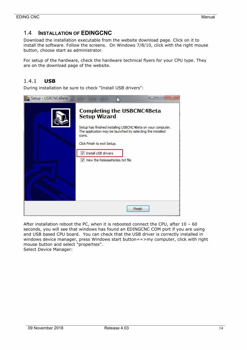
1.4.1 USB
During installation be sure to check "Install USB drivers":
After installation reboot the PC, when it is rebooted connect the CPU, after 10 – 60
seconds, you will see that windows has found an EDINGCNC COM port if you are using
and USB based CPU board. You can check that the USB driver is correctly installed in
windows device manager, press Windows start button==>my computer, click with right
mouse button and select "properties".
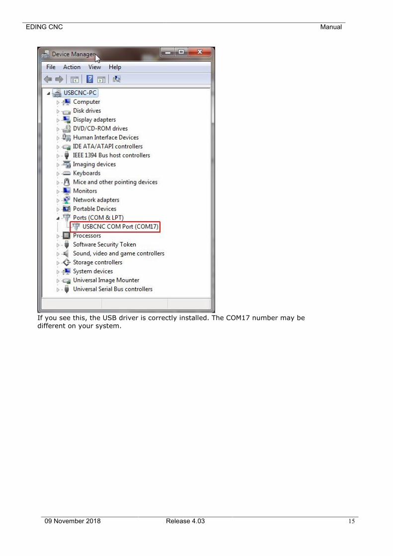
Select Device Manager:
EDING CNC Manual
09 November 2018 Release 4.03 15
If you see this, the USB driver is correctly installed. The COM17 number may be
different on your system.
EDING CNC Manual
09 November 2018 Release 4.03 16
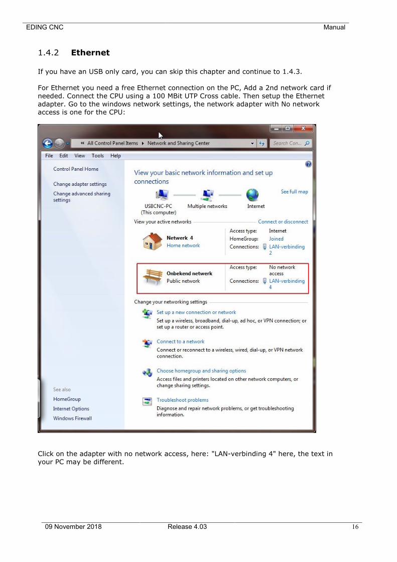
1.4.2 Ethernet
If you have an USB only card, you can skip this chapter and continue to 1.4.3.
For Ethernet you need a free Ethernet connection on the PC, Add a 2nd network card if
needed. Connect the CPU using a 100 MBit UTP Cross cable. Then setup the Ethernet
adapter. Go to the windows network settings, the network adapter with No network
access is one for the CPU:
Click on the adapter with no network access, here: "LAN-verbinding 4" here, the text in
your PC may be different.
EDING CNC Manual
09 November 2018 Release 4.03 17
.
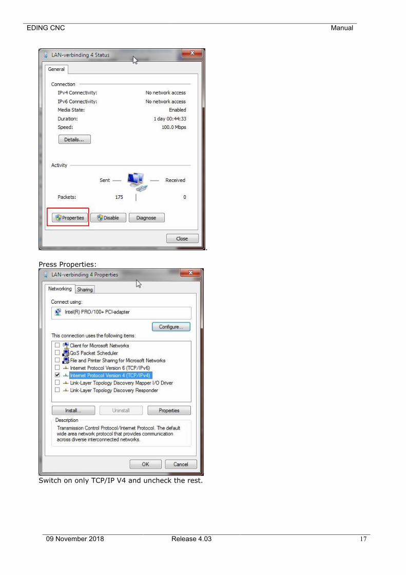
Press Properties:
Switch on only TCP/IP V4 and uncheck the rest.

EDING CNC Manual
09 November 2018 Release 4.03 18
Now press properties of the TCP/IP settings:
The PC LAN adapter gets IP Address 172.22.2.101.
The EDINGCNC CPU network is setup for 172.22.2.100.
Press OK, now you can test if the network is working, click the Windows Start button,
select all programs ==> accessories==>command prompt.
In the command prompt, enter ping 172.22.2.100, when connection OK, you should
see:
EDING CNC Manual
09 November 2018 Release 4.03 19
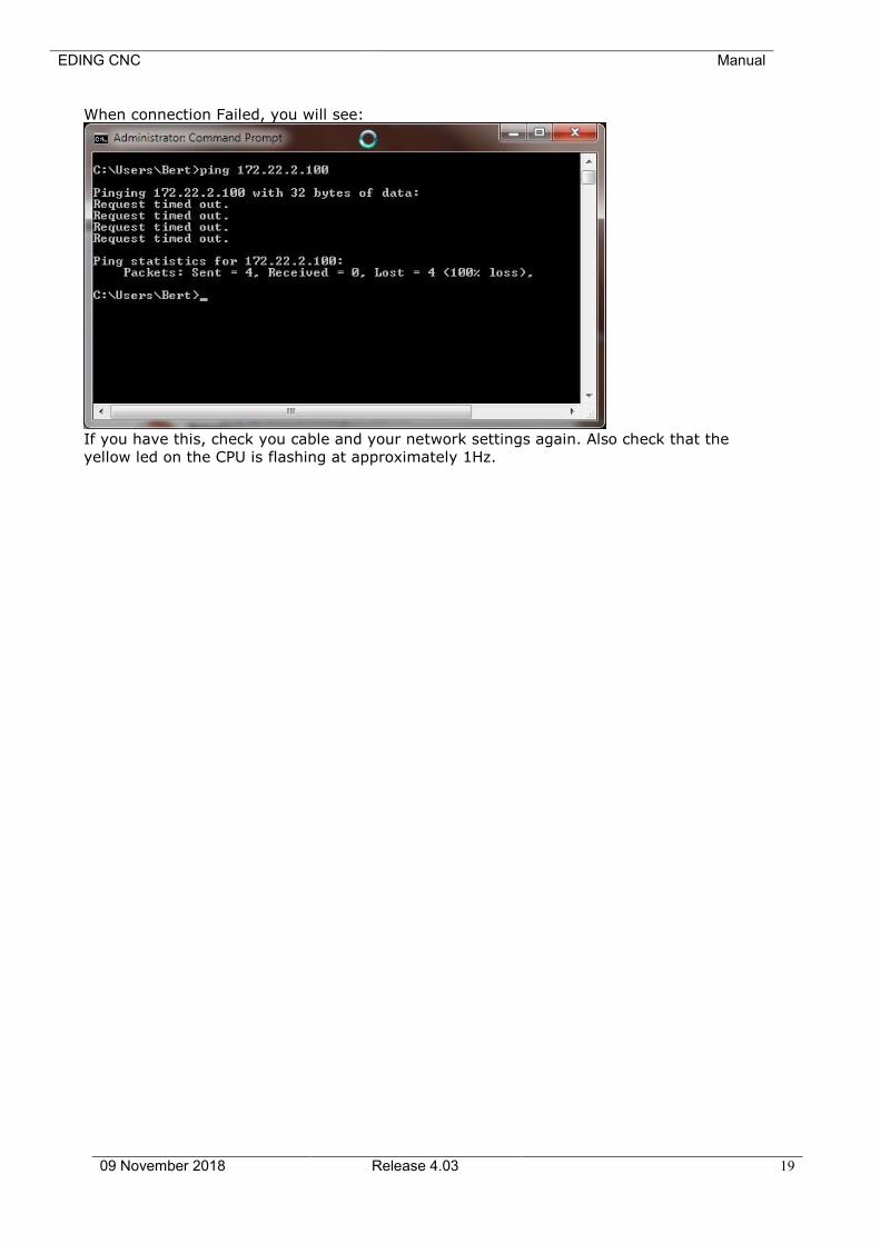
When connection Failed, you will see:
If you have this, check you cable and your network settings again. Also check that the
yellow led on the CPU is flashing at approximately 1Hz.
EDING CNC Manual
09 November 2018 Release 4.03 20
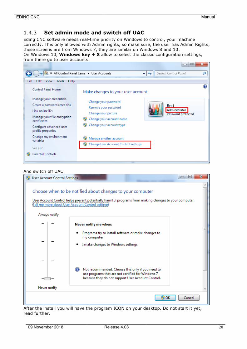
1.4.3 Set admin mode and switch off UAC
Eding CNC software needs real-time priority on Windows to control, your machine
correctly. This only allowed with Admin rights, so make sure, the user has Admin Rights,
these screens are from Windows 7, they are similar on Windows 8 and 10:
On Windows 10, Windows key + X allow to select the classic configuration settings,
from there go to user accounts.
And switch off UAC.
After the install you will have the program ICON on your desktop. Do not start it yet,
read further.
EDING CNC Manual
09 November 2018 Release 4.03 21
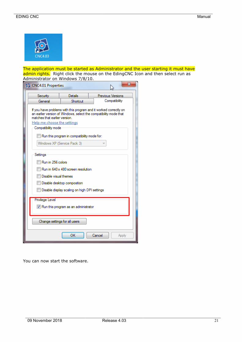
The application must be started as Administrator and the user starting it must have
admin rights. Right click the mouse on the EdingCNC Icon and then select run as
Administrator on Windows 7/8/10.
You can now start the software.
EDING CNC Manual
09 November 2018 Release 4.03 22
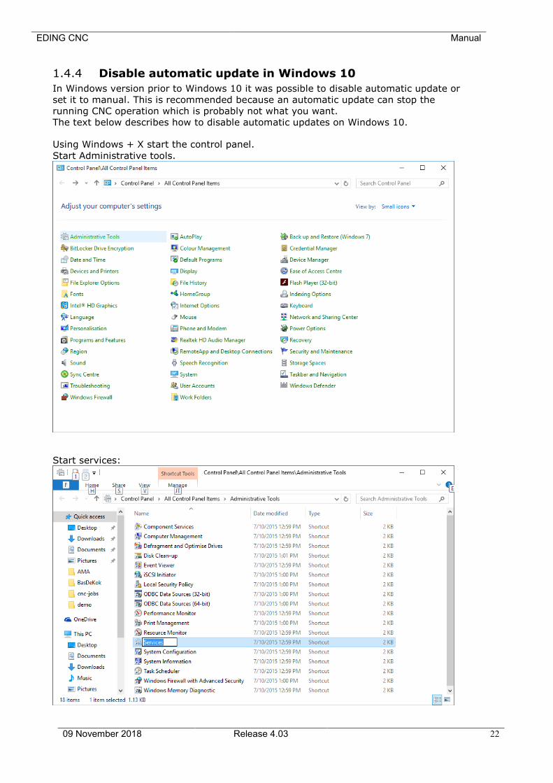
1.4.4 Disable automatic update in Windows 10
In Windows version prior to Windows 10 it was possible to disable automatic update or
set it to manual. This is recommended because an automatic update can stop the
running CNC operation which is probably not what you want.
The text below describes how to disable automatic updates on Windows 10.
Using Windows + X start the control panel.
Start Administrative tools.
Start services:
EDING CNC Manual
09 November 2018 Release 4.03 23
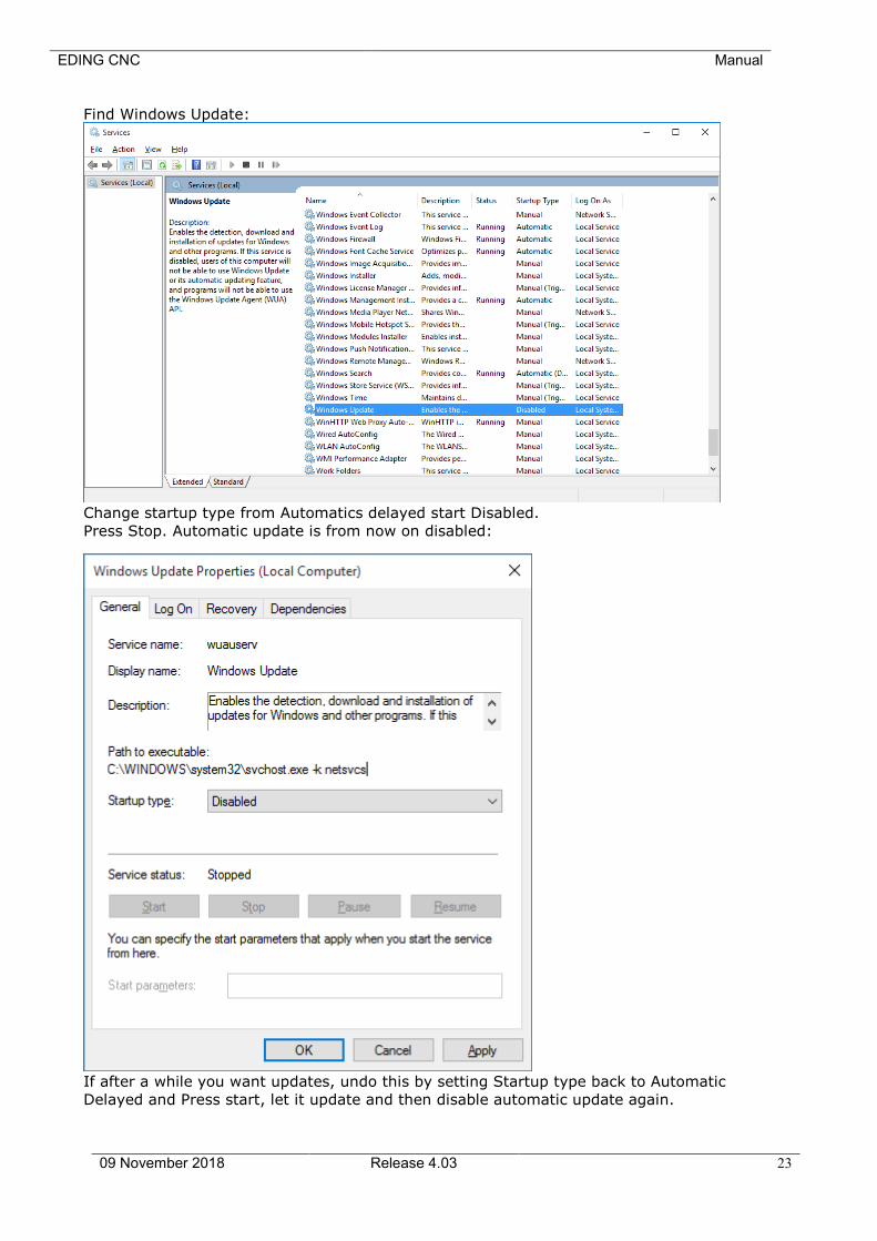
Find Windows Update:
Change startup type from Automatics delayed start Disabled.
Press Stop. Automatic update is from now on disabled:
If after a while you want updates, undo this by setting Startup type back to Automatic
Delayed and Press start, let it update and then disable automatic update again.
EDING CNC Manual
09 November 2018 Release 4.03 24
1.4.5 Connected drives not visible Windows 10
If you encounter that connected drives are not visible, her the explanation and how to
solve it. The drives are mapped using normal privileges when Windows is started up.
The EdingCNC software is started in Administrator mode because it needs Real-time
process priority. For Windows 10 this is a different user and the drives mapped for the
normal user are not visible due to this.
This can be solved by a setting called EnableLinkedConnections in the Windows
registry, this way:
Click Start, type regedit in the Start programs and files box, and then press ENTER.
Locate and then right-click the registry subkey
HKEY_LOCAL_MACHINE\SOFTWARE\Microsoft\Windows\CurrentVersion\Policies\System.
Point to New, and then click DWORD Value.
Type EnableLinkedConnections, and then press ENTER. Right-click
EnableLinkedConnections, and then click Modify. In the Value data box, type 1, and
then click OK. Exit Registry Editor, and then restart the computer.
Now everything works for you as expected.
EDING CNC Manual
09 November 2018 Release 4.03 25
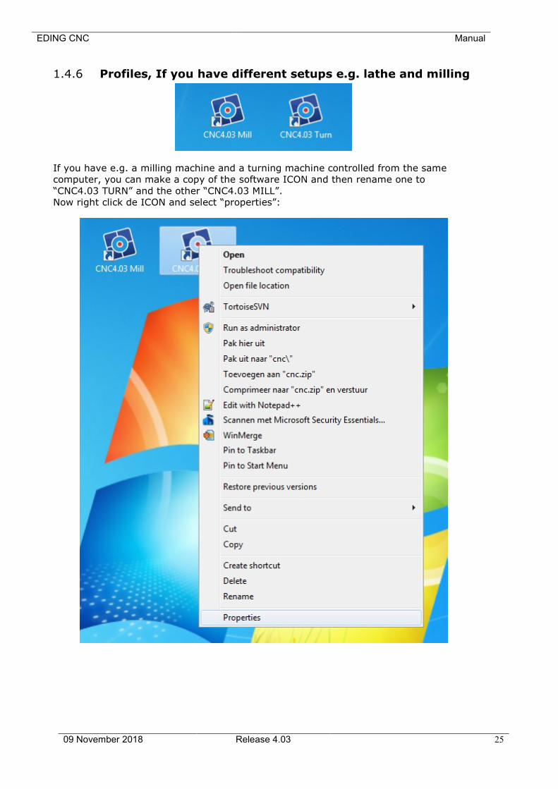
1.4.6 Profiles, If you have different setups e.g. lathe and milling
If you have e.g. a milling machine and a turning machine controlled from the same
computer, you can make a copy of the software ICON and then rename one to
“CNC4.03 TURN” and the other “CNC4.03 MILL”.
Now right click de ICON and select “properties”:
EDING CNC Manual
09 November 2018 Release 4.03 26
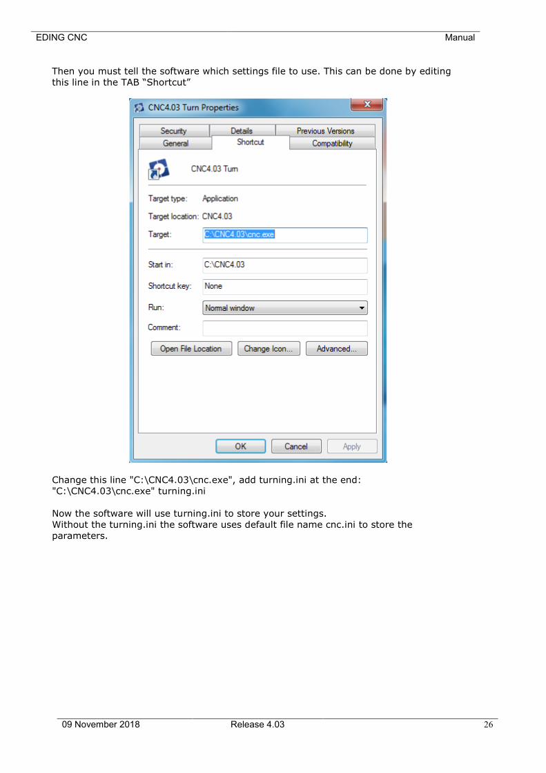
Then you must tell the software which settings file to use. This can be done by editing
this line in the TAB “Shortcut”
Change this line "C:\CNC4.03\cnc.exe", add turning.ini at the end:
"C:\CNC4.03\cnc.exe" turning.ini
Now the software will use turning.ini to store your settings.
Without the turning.ini the software uses default file name cnc.ini to store the
parameters.
EDING CNC Manual
09 November 2018 Release 4.03 27
2 The user interface
General info:
There are several views:
Operate , Program, Tools, Variables, Setup and Help.
Using control-tab, you can tab through them.
It is important that EDINGCNC is started started as administrator. On windows 7 this is
not automatically done like in XP.
Click on the right mouse button and select “Run As administrator”. You can also set this
in the ICON properties, compatibility.
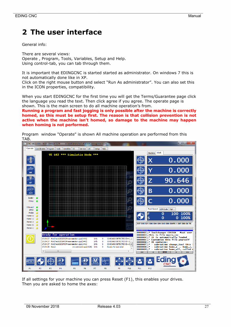
When you start EDINGCNC for the first time you will get the Terms/Guarantee page click
the language you read the text. Then click agree if you agree. The operate page is
shown. This is the main screen to do all machine operation’s from.
Running a program and fast jogging is only possible after the machine is correctly
homed, so this must be setup first. The reason is that collision prevention is not
active when the machine isn’t homed, so damage to the machine may happen
when homing is not performed.
Program window "Operate" is shown All machine operation are performed from this
TAB.
If all settings for your machine you can press Reset (F1), this enables your drives.
Then you are asked to home the axes:
EDING CNC Manual
09 November 2018 Release 4.03 28
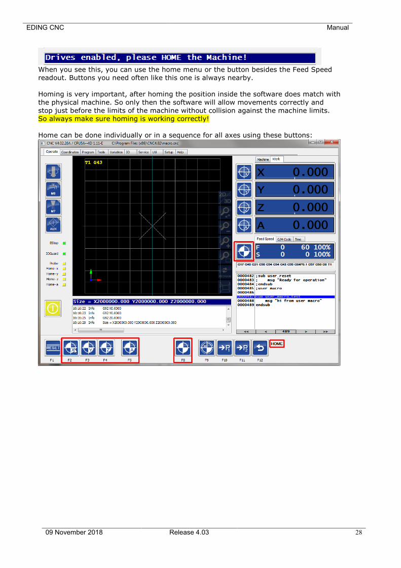
When you see this, you can use the home menu or the button besides the Feed Speed
readout. Buttons you need often like this one is always nearby.
Homing is very important, after homing the position inside the software does match with
the physical machine. So only then the software will allow movements correctly and
stop just before the limits of the machine without collision against the machine limits.
So always make sure homing is working correctly!
Home can be done individually or in a sequence for all axes using these buttons:
EDING CNC Manual
09 November 2018 Release 4.03 29
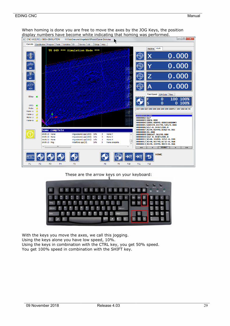
When homing is done you are free to move the axes by the JOG Keys, the position
display numbers have become white indicating that homing was performed.
These are the arrow keys on your keyboard:
With the keys you move the axes, we call this jogging.
Using the keys alone you have low speed, 10%.
Using the keys in combination with the CTRL key, you get 50% speed.
You get 100% speed in combination with the SHIFT key.

EDING CNC Manual
09 November 2018 Release 4.03 30
You can set the axes position by clicking the axis position display:
And you can also move the axes by holding the CTRL key and clicking with the left
mouse button on the position display.

EDING CNC Manual
09 November 2018 Release 4.03 31
2.1.1 Setup Pages
Before the system is actually used we have to setup the system to accommodate the
machine, we do that in the setup pages. There a two main setup pages:
2.1.2 UI and Connection
Connection to CPU: If you have 1 board connected to your PC, leave the setting at
AUTO, the software will find the board automatically. Otherwise
choose the here the CPU you want to work with. For CPU's with USB,
you see the COMx ports here, in case of a CPU5 with Ethernet, you
will see the IP-Address here.
Ethernet: If you have a CPU with Ethernet, check the Ethernet checkbox.
Max Step Frequency:
The maximum step frequency that the CPU will generate. For motor
drives it is needed to lower the maximum frequency. In case the drive
is unable to handle the high step frequency or low step-pulse width.
Some of the digital drives from Leadshine cannot handle 125Khz step-
rate, they need a setting of 90Khz or lower.
EDING CNC Manual
09 November 2018 Release 4.03 32
Language setup: Speaks for itself. After it is set, save the changes, then close
EDINGCNC and restart so that everything will be in the correct
language. The translations are in 2 files, cncgui-lang.txt and
cncserver-lang.txt, if you find translation mistakes you can correct
this here. Please send the corrected file to Eding CNC, the corrections
will then be incorporated into new versions.
Password: You can protect the setup parameters from being modified by
unauthorized persons by using a password. Leave empty if no
password is desired.
INCH: Machine setup is in inch mode.
MM: Machine setup is in mm mode.
2.1.3 Motor setup
Visible: Check if the axis should be visible in the GUI.
Port: Map axis to a physical output port of the CPU.
If an axis is mapped and not visible, it can still be used in the
interpreter.
Mode : Select mode for rotation axes, slave or special function:
• ROT, default, axis behaves as a normal rotation axis.
• SLAVE X, SLAVE Y or SLAVE Z axis is slave of X or Y or Z axes, for
Gantry machines with two independent (Tandem) motors on the
main axes. See also the Homing chapter for details on Slave axes.
• FOAM CUT for A-Axis, if used as a Foam cutter with 4 linear axes.
X is the left horizontal axis, Y is the left vertical axis, A is the right
horizontal axis and Z is the right vertical axis. Feed calculation are
based on the X/Y or A/Z combination which ever makes the
biggest distance,
• 4th MILL, if used in 4 axes milling. Feed calculations are optimized
such that the tooltip gets the correct speed relative to the
material.
• Tangential Knife, this option is available for the C-Axis only. The
Knife will rotate in the movement direction of X-Y. See also
trajectory setup.
• 2nd Z, for machines with 2 Z axes, where the A axis is used as
the 2nd Z.
Steps/AppUnit :
Fill in number of steps per millimeter for millimeter mode or number
of steps per inch for inch mode. For rotary axes, the unit is always
steps per degree. Fill in a negative number to reverse the motor
direction.
Example: Suppose your driver is set to 1600 steps/revolution (1/8
micro step) and you have coupled the motor directly to a spindle with
5mm pitch. The number to be filled in here = 1600 / 5 = 320.
If the movement direction is wrong, change it to -320.
EDING CNC Manual
09 November 2018 Release 4.03 33
Positive limit: Maximum machine position.
Negative limit: Minimum machine position;
Vel : Maximum axis velocity, all velocities, whether jogging, G0/G1/G2/G3
are limited to this value.
Acc: Maximum acceleration.
When this value is set equal to the Vel parameter, it will take 1
second to reach the max velocity. When the value is 2x the Vel
parameter, the max velocity is reached in 0.5 second.
EDING CNC Manual
09 November 2018 Release 4.03 34
2.1.4 Homing and ESTOP setup
Home Vel/Dir: Homing velocity, a negative number reverses the homing direction.
When the velocity is set to 0, the axis is homed manually, see the
homing and coordinate systems chapter.
Home Position: Machine position at the moment the home switch activated. This
determines the machine coordinates. It is not really relevant where
the machine zero point lies, it should only match with the MIN/MAX
position.
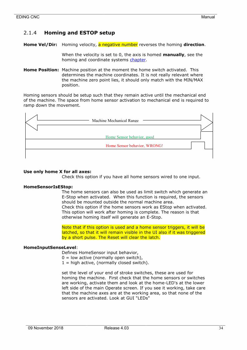
Homing sensors should be setup such that they remain active until the mechanical end
of the machine. The space from home sensor activation to mechanical end is required to
ramp down the movement.
Use only home X for all axes:
Check this option if you have all home sensors wired to one input.
HomeSensorIsEStop:
The home sensors can also be used as limit switch which generate an
E-Stop when activated. When this function is required, the sensors
should be mounted outside the normal machine area.
Check this option if the home sensors work as EStop when activated.
This option will work after homing is complete. The reason is that
otherwise homing itself will generate an E-Stop.
Note that if this option is used and a home sensor triggers, it will be
latched, so that it will remain visible in the UI also if it was triggered
by a short pulse. The Reset will clear the latch.
HomeInputSenseLevel:
Defines HomeSensor input behavior,
0 = low active (normally open switch),
1 = high active, (normally closed switch).
set the level of your end of stroke switches, these are used for
homing the machine. First check that the home sensors or switches
are working, activate them and look at the home-LED's at the lower
left side of the main Operate screen. If you see it working, take care
that the machine axes are at the working area, so that none of the
sensors are activated. Look at GUI "LEDs"
Machine Mechanical Range
Home Sensor behavior, good
Home Sensor behavior, WRONG!
EDING CNC Manual
09 November 2018 Release 4.03 35
EStopInputSenseLevel1:
Defines EStop input behavior,
0 = low active (NO switch CPU5 series, NC switch iCNC600),
1 = high active, (NC switch CPU5 series, NO switch iCNC600).
2 = OFF, not used
EStopInputSenseLevel2, CPU5B only:
Defines EStop input behavior for second EStop input,
0 = low active (normally open switch),
1 = high active, (normally closed switch).
2 = OFF, not used
ExtErrInputSenseLevel, CPU5B and iCNC600 ONLY:
Defines External Error input behavior (CPU5B only),
0 = low active, e-stop (NO switch CPU5B, NC switch iCNC600),
1 = high active, e-stop (NC switch CPU5B, NC switch iCNC600).
2 = OFF, not used
3 = low active, smooth stop
4 = high active, smooth stop
With smooth stop the axes speed is ramped down, this means that
there is no position loss.
The polarity settings for the home inputs, E-stop's and Extern error can be automatically
determined by pressing the "Auto detect polarity" button.
Note that if the estop or extern-error input triggers, it will be latched, so that it will
remain visible in the UI also if it was triggered by a short pulse. The Reset will clear the
latch.
ExtErrInputSenseLevel via Sync input, CPU5A ONLY:
CPU5A do not have an ExtErr input, but applications that do need this
function, can use the Sync input with limited functionality
Defines External Error input behavior (CPU5A only),
3 = low active, smooth stop
4 = high active, smooth stop
With smooth stop the axes speed is ramped down, this means that
there is no position loss.
SafeFeed:
Defines the max velocity [mm/second] used for jogging and running if
the safety input is active or if the machine is not yet homed.
2.1.5 Backlash setup
Backlash: Set the amount of backlash for each axis that the software should
compensate. Experiment with velocities and acceleration, the backlash
compensation demands more from acceleration your motors than
EDING CNC Manual
09 November 2018 Release 4.03 36
without backlash compensation. Do not try to compensate more than
0.1 millimeters. If there is more backlash, try to reduce it
mechanically first.
2.1.6 LAF setup
LAF minimum angle:
Look Ahead Feed calculations: Motion segments (g1,g2,g3) that are
connected with a smaller angle as specified in min.angle will
accelerate through which will give higher speeds especially with
programs consisting of small motion segments. This is a unique
feature which you don’t find easily on low cost CNC controllers.
Be carefully with the min.angle setting because this cause
acceleration spikes, it depends on your machine and the speed up till
what extend this is possible. I suggest performing tests with en check
whether you get step pulse loss.
A value of 0.1 .. 3 degrees is generally safe. Segments that are really
tangential connected will move fast that way.
An example of what I use:
When using CorelDraw, a circle is drawn of 100mm in diameter, and
exported as HPGL CorelDraw generates small line segments of
approximately 6 degrees. Now I have set the min.angle to 6, this
gives the possibility to mill the circle with a speed of F6000 while
without LAF the speed would be approx F1300 on my machine.
There are other run-time modifiable settings for LAF, see G64.
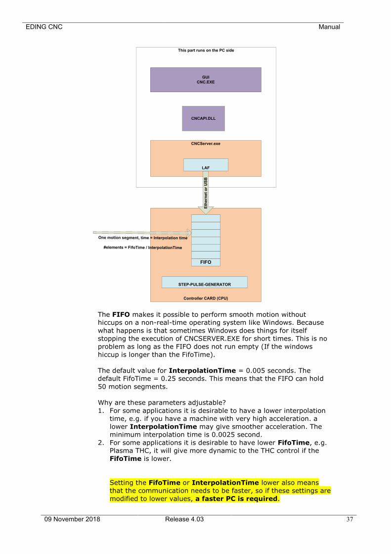
InterpolationTime and FifoTime:
Every motion command is chopped up in small motion segments with
a time of InterpolationTime in the setup.
The segments are send to the controller (CPU) which has a buffer
(FIFO) that holds the motion segments. The step-pulse generator
takes the motion segments one by one and generates stepper motor
pulses from that. The number of the segments in the FIFO is
depending on the FifoTime specified in the setup.
EDING CNC Manual
09 November 2018 Release 4.03 37
Controller CARD (CPU)
FIFO
CNCServer.exe
GUI
CNC.EXE
CNCAPI.DLL
STEP-PULSE-GENERATOR
LAF
This part runs on the PC side
Eth
ern
et
or
US
B
One motion segment, time = Interpolation time
#elements = FifoTime / InterpolationTime
The FIFO makes it possible to perform smooth motion without
hiccups on a non-real-time operating system like Windows. Because
what happens is that sometimes Windows does things for itself
stopping the execution of CNCSERVER.EXE for short times. This is no
problem as long as the FIFO does not run empty (If the windows
hiccup is longer than the FifoTime).
The default value for InterpolationTime = 0.005 seconds. The
default FifoTime = 0.25 seconds. This means that the FIFO can hold
50 motion segments.
Why are these parameters adjustable?
1. For some applications it is desirable to have a lower interpolation
time, e.g. if you have a machine with very high acceleration. a
lower InterpolationTime may give smoother acceleration. The
minimum interpolation time is 0.0025 second.
2. For some applications it is desirable to have lower FifoTime, e.g.
Plasma THC, it will give more dynamic to the THC control if the
FifoTime is lower.
Setting the FifoTime or InterpolationTime lower also means
that the communication needs to be faster, so if these settings are
modified to lower values, a faster PC is required.
EDING CNC Manual
09 November 2018 Release 4.03 38
FIFO UNDERRUN ERROR
If this happens then this indicates that the PC is too slow to keep
the FIFO full.
Possible causes are:
• PC too slow.
o The processor is too slow. (recommended minimum
is 1.3 GHz duo-core processor, 2G RAM for 32bit
Windows, 4G RAM for 64 bit Windows. If you
execute large 3D g-code files > 10 Million lines, 4G
RAM or more is recommended.
o Too little memory in the PC (can be checked in task
manager, there must always be Physical memory
available, if the system starts swapping to disk
because the memory is all used, changes on FIFO
UNDERRUN is high).
o PC has switched to energy saving mode and has
become slow. So always adjust the energy saving
settings such that there is maximum performance
always.
o Because you suddenly get an automatic Windows
Update, so always switch off automatic Update and
perform updates manually when you want.
o Because virus checkers become active making the
system slow. So always turn off anti-virus check
when running the CNC controller.
• USB communication too slow or EMI disturbance that
corrupts the communication.
Take care that your cabinet is wired according EMC rules,
you can find some tips at the end of this manual.
If the USB chipset is slow, you could solve it by using a PCI
USB add-on card. If this is not possible, you need another
PC.
• Ethernet communication too slow. This could happen if the
settings are not 100% equal to what is described in the
setup. E.g. for the used adapter card only the TCPIP
protocol must be on and all others must be OFF. There
must be a 1:1 connection from Controller Board to the PC
using a CROSS CAT5E cable. So you cannot connect the
CPU as part of your home network, it must be on a
separate network adapter.
Theoretically also Ethernet may suffer from EMI
disturbances due to bad unshielded cabling. In practice
Ethernet is very robust to this. Anyway always make the
wiring with the EMC rules in mind. See hardware tips at the
end of the manual.
There is also this experience, heavy browsing on internet
while doing CNC may cause FIFO UNDERRUN error,
especially on Windows XP. Windows 7 and Windows 8 are a
lot better than Windows XP with this.
EDING CNC Manual
09 November 2018 Release 4.03 39
G0 Feed Factor:
With this you can apply a factor for the feed used at G0, this allows
different feeds for G0 positioning G1/G2/G3 milling.
G0 Acc Factor:
With this you can apply a factor for the acceleration used at G0, this
allows different acceleration for G0 positioning G1/G2/G3 milling.
FeedOverride input:
You can select “UI”, “UI & Hand wheel” (Default) or “analogue input 1
– 3” on the CPU, with analog input you can use a potentiometer to
control the feed override, recommended potentiometer value is 4K7.
When UI and hand wheel is selected you can control the Feed
Override using the F+ and F- buttons and the Hand wheel to control
the feed Override from 0-300%. Note that the machine will not go
faster than the maximum velocities of the motors allow.
FeedHold input: Here you can select a digital input from the CPU that sets the Feed
Override to zero immediately when activated. When released the Feed
Override will go back to the value before. This function may be used
by EDM machines to stop the feed when there is a short circuit
detection of the electrode.
2.1.7 Kinematic Setup
Trivial kinematics:
It is not needed for normal Cartesian machines, leave the Trivial 1:1
kinematics checked. Please contact Eding CNC if you have a special
machine or robot with non-Cartesian axes.
2.1.8 Tool change Area setup
XYZ Limits: By setting the limits here to a value different from zero, the TCA (Tool
Change Area) guard will be activated. Using the values here you
define an area on the machine which is restricted to tool change. A
normal work piece program is not allowed to enter this area.
You can also not jog in this area or move to this area by MDI.
If you need to be in this are issue command "TCAGuard off" To re-
enable the protection "TCAGuard on".
Z DownToolLength:
For machine configurations where the tool chuck does not touch the
machine bed when the machine is at its lowest Z position. Here you
specify the tool length of the tool that fits when Z is at its lowest
position.
This information is important for collision guarding.
2.1.9 Tangential knife setup
TanKnife Angle:
Tangential Knife is a rotation motor (the C Axis) around Z. Tangential Knife works
EDING CNC Manual
09 November 2018 Release 4.03 40
with normal G1, G2, G3 without tool-radius compensation G41, G42. The knife is
rotated automatically in the direction of the X-Y move. This parameter determines
the angle which 2 lines/Arcs can make without lifting the Z. If the angle is greater
as this value, the Z will move up (G0), rotate the knife (G0), then move down
again (G1). If the angle is lower, the rotation will take place without moving Z up.
TanKnife Z up distance:
Specifies the distance to lift up Z when detected angle is greater than Tan Knife
Angle.
TanKnife blend angle and blend distance:
When subsequent lines have an angle with current line which is less than the blend
angle and when the subsequent line or arc length is less than specified length the
knife is not rotated before the move but during the move. For small angles in
combination with small segment lengths this is in practice tolerable and will speed
up the cutting process a lot. Be aware however that the knife direction is not
exactly in the cutting direction and my break if the angle is too large.
The tangential knife is switched on and configured by interpreter commands.
These commands can be typed in MDI, part of the G-Code or hooked under the user
buttons in macro.cnc.
;Switch tan knife on or off. Tan knife must first be configured in the setup.
Tanknife off
Tanknife on
;map tan knife to B or C or both axis output.
Tanknife b
Tanknife c
Tanknife bc
Especially for BEND tangential knife
Tanknife lo <lo-position>
Define the low Z value in work coordinates, this is the deepest point in the groove (*).
Tanknife hi <hi-position>
Define the high Z position in work coordinates, usually is 1-5mm above the material (*).
Tanknife bend -1 | 1 define the direction to which the knife is bend for a 45 degree
knife (*).
Tanknife rw <nr of turns> knife will be rotated back after nr of turns (anti-windup of
wires). (*).
Tanknife lu <lift up distance> set new lift up distance for rotating. (*).
(*) These parameters are saved and used next time with Tanknife on command.
For usage of tangential knife that is bend 45 degree do calibration of the hi and lo
position first. Then switch the knife on by tanknife bend -1 or +1 depending on the side
to which it is bend. Set the C position to 0 when the sharp edge is pointing straight to
the +X direction.
EDING CNC Manual
09 November 2018 Release 4.03 41
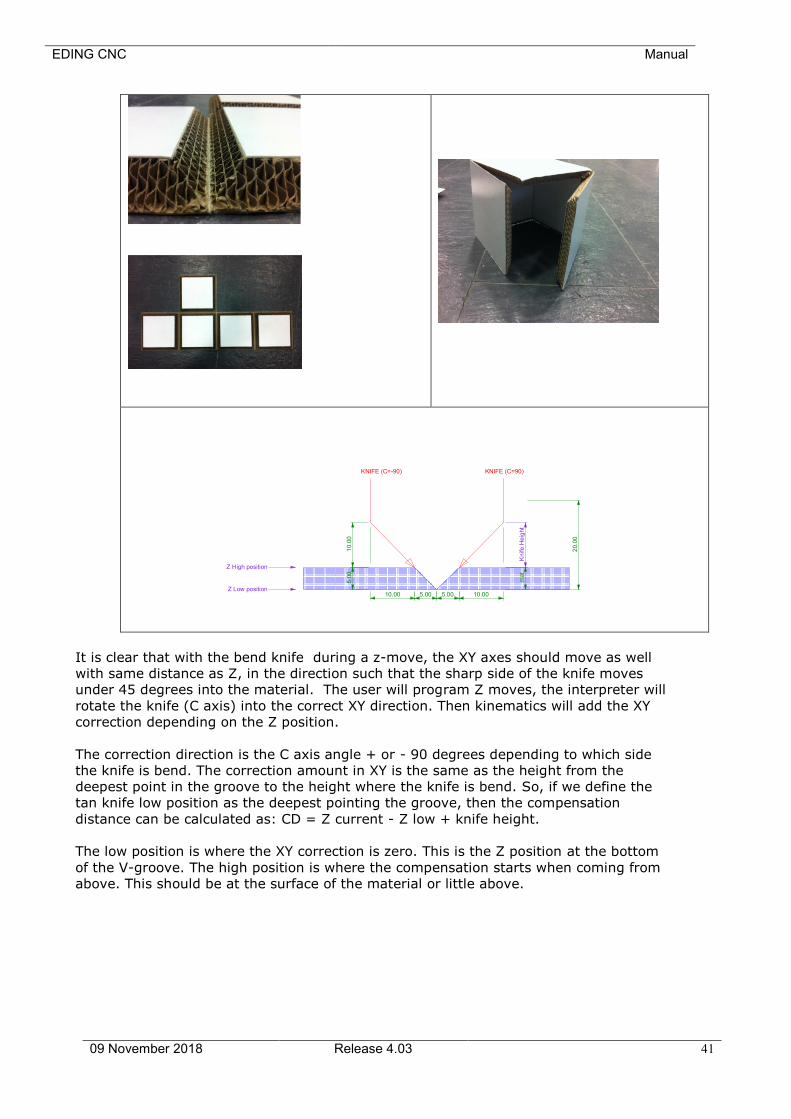
It is clear that with the bend knife during a z-move, the XY axes should move as well
with same distance as Z, in the direction such that the sharp side of the knife moves
under 45 degrees into the material. The user will program Z moves, the interpreter will
rotate the knife (C axis) into the correct XY direction. Then kinematics will add the XY
correction depending on the Z position.
The correction direction is the C axis angle + or - 90 degrees depending to which side
the knife is bend. The correction amount in XY is the same as the height from the
deepest point in the groove to the height where the knife is bend. So, if we define the
tan knife low position as the deepest pointing the groove, then the compensation
distance can be calculated as: CD = Z current - Z low + knife height.
The low position is where the XY correction is zero. This is the Z position at the bottom
of the V-groove. The high position is where the compensation starts when coming from
above. This should be at the surface of the material or little above.
10.00
20.0
0
10.0
05
.00
mat
10.005.005.00Z Low position
Knife
He
ight
Z High position
KNIFE (C=-90) KNIFE (C=90)
EDING CNC Manual
09 November 2018 Release 4.03 42
Practical example:
;Test tangential knife
;Cut 2 lines
;Top of material Z is 0
;V cut 5mm deep
;
Tanknife hi 1.0 ;Start combined move 1mm above material surface
Tanknife lo -5.0 ;Deepest Z value in V groove
Tanknife bend 1 ;Note that bend can be -1 as well, depending on the
;knife construction.
G0 Z10 ;move above the material and above tanknife hi position
Tanknife on ;Do this before moving to the starting point.
G0 X0 Y0 ;Starting point
G1 F200 Z-5 ;Knife into material deepest point in groove.
G1 F500 X100 ;Cut 100mm in X
G1 Y100 ;and 100mm in Y
G1 Y0 ;and backwards to make a V groove
G1 X0
G0 Z10 ;done Z up
Tanknife off ;Knife off
M30
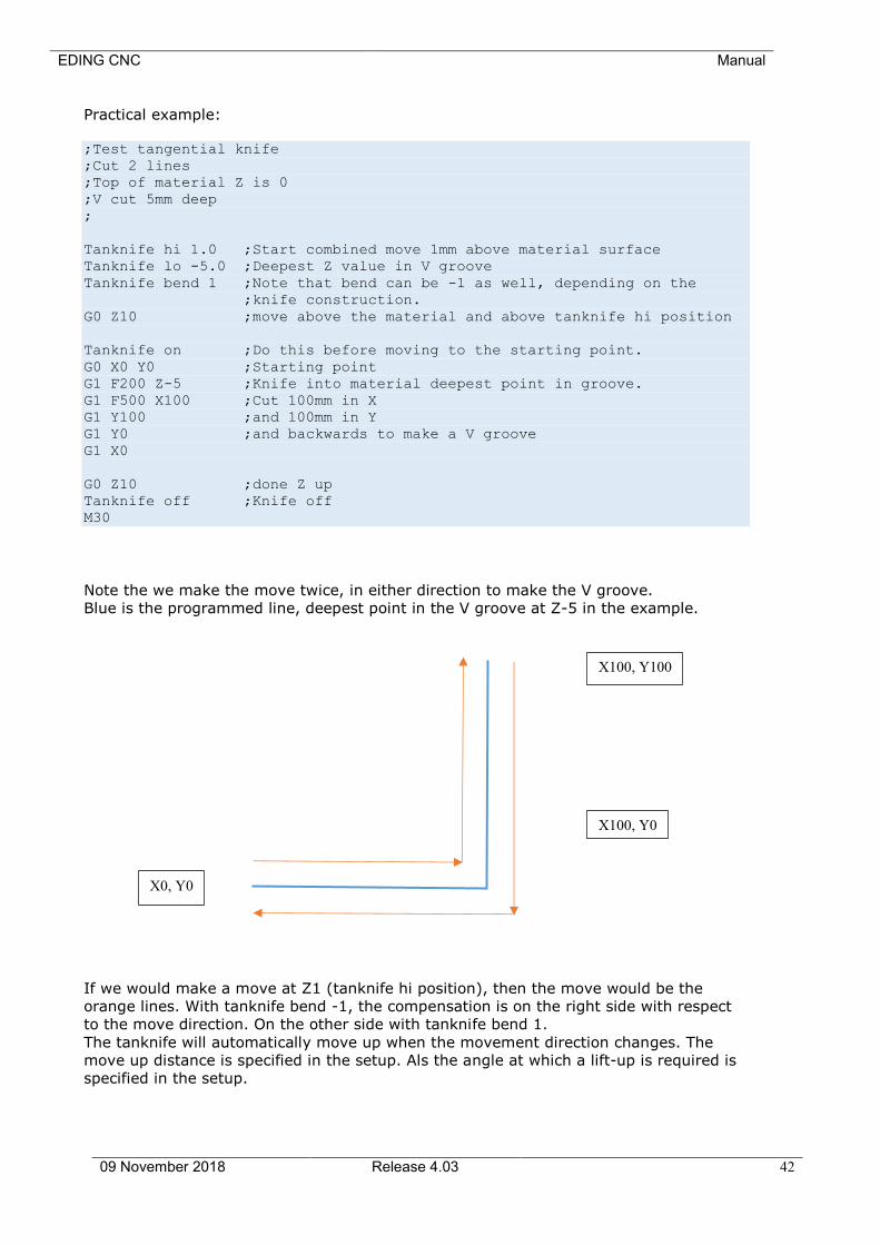
Note the we make the move twice, in either direction to make the V groove.
Blue is the programmed line, deepest point in the V groove at Z-5 in the example.
If we would make a move at Z1 (tanknife hi position), then the move would be the
orange lines. With tanknife bend -1, the compensation is on the right side with respect
to the move direction. On the other side with tanknife bend 1.
The tanknife will automatically move up when the movement direction changes. The
move up distance is specified in the setup. Als the angle at which a lift-up is required is
specified in the setup.
X0, Y0
X100, Y0
X100, Y100

EDING CNC Manual
09 November 2018 Release 4.03 43
2.1.10 Safety/Door open Input setup
Safety Input Selection: Select one of the AUX inputs to act as safety input, when
active, only low speeds are possible and the running g
code goes to pause (Feed hold, spindle off). This can only
be configured for CPU5B.
For professional users, there is more that can be
configured in the parameters file, cnc.ini:
Each AUX input can be setup to be guarded run time an
stop the running program or give a warning.
[SAFETY]
aux1InputCheckSenseLevel = 2
;Where 0,1,2=no action, 3=sstopOnLow, 4=stopOnHigh,
5=slowFeedOnLow, 6=slowFeedOnHigh, 7=warningOnLow,
8=warningOnHigh
Safety Feed: Feed in [mm/s] to be applied when the safety input is
active and when the machine is not homed and homing is
mandatory is set.
Intended use is for a door switch.
Related to this functionality, there are these variables to be set (cnc.ini only)
noStartSpindleIfPauseActive:
when set to 1, the spindle cannot be switched on if the
pause input is active.
noStartJogIfPauseActive:
When set to 1, jogging the axis is not possible if the pause
input is active.
2.1.11 Spindle and PWM setup
MinS: The lowest possible speed for you spindle. If a command
for a lower S values is used, then this minimum value is
applied.
MaxS: The speed of your PWM controlled spindle when the PWM
signal is at 100%.
Ramp up Time: The software waits this time between switching on the
spindle and starting the further machining.
StopOnPause: Stop spindle when pause is activated.
zUpOnPause: Z goes automatically up when pause is activated.
EDING CNC Manual
09 November 2018 Release 4.03 44
autoStartAfterPause: When start is pressed, the X,Y axes automatically
reposition to the pause position, the spindle is started,
then the Z goes down with approach feed and the program
continues.
zUpDistance: Hom much the Z goes up when when pause is activated
and zUpOnPause is active. Software will protect against
going up beyond the Z limit.
approachFeed: The feed used for Z down when autoStartAfterPause is on
and the start button is pressed.
RPMSensor: Check if you have connected a spindle speed sensor to the
Sync input of the CPU. The sensor should give 1
pulse/revolution, minimum pulse width 0.5ms.
MistIsSpindleDirection: Special for CPU5A, use mist output for spindle direction if
you need it (CPU5A has no separate spindle direction
output, that is why).
IsStepperMotor: Step/Direction pulses will be generated if set instead of
PWM. A Stepper motor or Servo Spindle can be connected
to the PWM/TOOL-DIR output when selected.
SmoothStep: Only in combination with IsStepperMotor, when checked
the ramp-up-profile is smoother than when not checked,
however when checked PWM2/PWM3 on the CPU5B cannot
be used as separate PWM output anymore..
CountsPerRev: Provide the number of steps/revolution here if
IsStepperMotor is checked.
SpeedOverrideInput: Specify UI or analogue input for controlling the speed
(CPU5B).
SpeedHoldInput: Specify digital input for speed hold, when activated spindle
speed goes to zero. When release spindle restarts. Some
applications need this functionality.
SpindleReadyPortID: User definable input which indicates that the spindle has
reached it speed. It is currently only available by editing
the cnc.ini file.
showInProgSpeed: This setting is under [USERINTERFACE] in the cnc.ini file.
It can have these values:
0: Show programmed speed (Default)
1: Show PWM value
2: Show analog in 1
3: Show analog in 2
4: Show analog in 3
hese options are convenient if the spindle has an analog
output for power measurement.
showInProgSpeedAnaMulFactor :

EDING CNC Manual
09 November 2018 Release 4.03 45
Multiplcation factor for the analog value for option 2-4 with
showInProgSpeed.

EDING CNC Manual
09 November 2018 Release 4.03 46
Setup Page 2, press ">" button on first setup page to get here:
2.1.12 UI setup items
Invert JogKeys: Inverts the movement of the keyboard keys, for moving bed
machines, the bed moves in the direction you press the arrow.
IsTurningMachine: Check if your machine is a Lathe, this effects mainly the 3D display
which shows the X-Z plane for turning. Also the jog keys operate
differently. Futher the working plane is set to G18 (X-Z).
ShowStartupScreen: When checked, the startup screen is shown when
EDINGCNC starts.
HomingMandatory: When checked, running a job and mdi is not allowed before the
machine is homed. Also the jog speed is limited to 5% speed. This
feature prevents damage to your machine because when the
machine isn’t homed, the limit guards are not working. So, I
advise to leave this item checked always.
SimpleZeroing: If checked, the zero buttons (beside the position display), will
simply set the work position to zero. If this item is not checked, a
dialog will be shown in which you can set the position. Default it
shows a value which is – tool-radius of the current tool. This is
handy when zeroing from the lower left corner with the endmill
against the material.
EDING CNC Manual
09 November 2018 Release 4.03 47
G10L20Zeroing: If checked the active coordinate system (G54 – G59.3) is zeroed
instead of the global G92.
If not checked the global G92 global method is used.
AutoToolChange: If checked the running job will not stop when a tool change is
encountered. Use this when you have a ATC or if you simply always
have the tool already in.
ShowMaximized: GUI will start maximized taking the whole screen.
ShowM7: Show or hide M7 button
ShowM8: Show or hide M8 button
ShowAUX1: Show or hide AUX1 button
KeyboardTimeout: Time out is used while jogging. This feature is introduced because
of the use of Bluetooth keyboards. It could happen that jog start is
pressed, but never released (jog stop) because to keyboard is no
longer in reach. The timeout will automatically jog stop of needed.
The default value of 1s is OK for most PC’s. I do not recommend to
set it lower because you may get unwanted time-outs.
REMARK: More ShowXXX options are available under
[USERINTERFACE] in the configuration file cnc.ini.
ShutDownOnFatal: If checked software will shut down automatically when a fatal error
such as disconnected CPU occurs. This may be used when the
electrical power is switched of and connection to the CPU gets lost.
Favorite Editor: Specify your favorite editor here. I recommend notepad++, it is
freely downloadable at internet. E.g. for notepad++, specify
c:\program files\notepad++\notepad++.exe.
The advantage of notepad++ is that the editor jumps to the actual
G-Code line immediately, very handy when programming G-Code.
IconDirectory: The name of the directory where the GUI icons are located.
nu means not used.
If you want to change the Icons on the buttons, you can make first
a copy of the entire icons and name that directory to myIcons.
Make your changes an place the directory name in this field.
OpenGL: Check to use OpenGL graphics. This allows smooth panning,
zooming and rotation using the mouse.
Left mouse key; Pan
Right mouse key: Zoom
Control + Left mouse key: Rotate.
OpenGLPenSize: Set PEN size shown in graphic, size is in millimeter.
2.1.13 IO setup
Invert IO: Check if you want to invert the output.
EDING CNC Manual
09 November 2018 Release 4.03 48
2.1.14 Interpreter settings
DiameterProgramming:
Check if you want diameter programming for turning, all X-axis
values are interpreted as diameter. The effect is that all
movements in the X-axis are divided by 2.
AbsoluteCenterCoords:
If Checked, the I,J,K value is interpreted as absolute value.
Incremental is used mostly.
LongFileModeCriterion:
Specify a number of Kbytes here. When the loaded job file is
larger, the UI switches to long file mode. The program listbox
changes and the graphics will show only outlines when a program
is loaded. This is all needed to preserve memory and speed for
large files.
In this mode the file itself is still executed from memory and allows
complex G-Code constructs (While, If then else, sub routines).
SuperLongFileModeCriterion:
Specify a number of KBytes here where super long file mode starts.
This number should be equal or bigger as LongFileModeCriterion.
For very long files from 20MByte and UP to 4G this mode is
required. It also puts the GUI in the same mode as with
LongFileMode, but as extra, the file itself is no longer executed
from memory. The means that complex G-Code constructs are no
longer possible. These type of files contain only straight forward g-
code without "while-endwhile", "if-then-else" and "subroutines".
The tool changes are still executed from the macro.cnc file, so full
automatic tool change is still available.
Files with up to 100.000.000 lines of G-Code have been tested with
this.
Macro Filename: Name of the macro file, it can be changed, the default is
macro.cnc.
User Macro Filename: Name of the macro file, it can be changed, the default is
macro.cnc.
2.1.15 Traffic light setup
Red: Specify output for RED color.
Yellow: Specify output for YELLOW color.
Green: Specify output for GREEN color.
CPU5B is required to view all colors because other CPU's do not have
enough amount of outputs.
EDING CNC Manual
09 November 2018 Release 4.03 49
2.1.16 JobTimeEstimation
During the Render phase, after loading the job, the job time is estimated. But this is just
a quick estimation because a real calculation of time would take too much time,
therefore these parameters:
CorrectionFactor: Correction factor for the time calculations, you can change this if
you see that your type of jobs require a correction.
RestimateRunTime: When checked, you will see the remaining estimated time of job
based on the average speed measured and the total distance to
go.
2.1.17 Hand wheel Setup
Cnt/Rev: The number of counts of the hand wheel for one revolution, usually
400 for most CNC hand wheels.
Count: Shows the actual Hand wheel count value, try to turn the hand
wheel and see it change.
V[%]: Percentage of velocity from selected axis, this is the maximum
velocity the axis will move when using the hand wheel.
A[%]: Percentage of acceleration from selected axis, this is the maximum
acceleration the axis will move when using the hand wheel..
X1..X100 Vel Mode:In velocity mode the most important is that the movement stops
immediately when the rotation of the hand wheel stops. The
position of the hand wheel will not be maintained if velocity mode
is on. The position of the handheld is maintained if velocity mode
is off. This also means that the axis may not immediately stop if
the hand wheel rotation stops. When turning beyond the limits of
the axis, you have to turn back the hand wheel the same amount
before the axis starts moving again.
My own experience is that it works best to use velocity mode at
X100 only. Jus play with it to experience the behavior and make
your own choice.
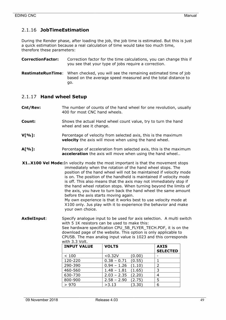
AxSelInput: Specify analogue input to be used for axis selection. A multi switch
with 5 1K resistors can be used to make this:
See hardware specification CPU_5B_FLYER_TECH.PDF, it is on the
download page of the website. This option is only applicable to
CPU5B. The max analog input value is 1023 and this corresponds
with 3.3 Volt.
INPUT VALUE VOLTS AXIS
SELECTED
< 100 <0.32V (0.00) -
120-220 0.38 – 0.71 (0.55) 1
290-390 0.94 – 1.26 (1.10) 2
460-560 1.48 – 1.81 (1.65) 3
630-730 2.03 – 2.35 (2.20) 4
800-900 2.58 – 2.90 (2.75) 5
> 970 >3.13 (3.30) 6
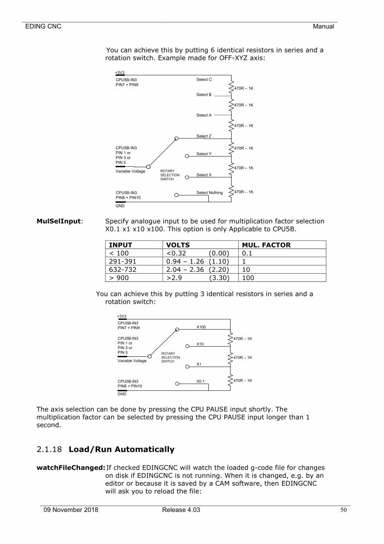
EDING CNC Manual
09 November 2018 Release 4.03 50
You can achieve this by putting 6 identical resistors in series and a
rotation switch. Example made for OFF-XYZ axis:
Select Nothing
Select X
Select Y
Select Z
Select A
Select B
Select C
470R – 1K
CPU5B-IN3
PIN8 + PIN10
CPU5B-IN3
PIN 1 or
PIN 3 or
PIN 5
CPU5B-IN3
PIN7 + PIN9
470R – 1K
ROTARY
SELECTION
SWITCH
+3V3
GND
Variable Voltage
470R – 1K
470R – 1K
470R – 1K
470R – 1K
MulSelInput: Specify analogue input to be used for multiplication factor selection
X0.1 x1 x10 x100. This option is only Applicable to CPU5B.
INPUT VOLTS MUL. FACTOR
< 100 <0.32 (0.00) 0.1
291-391 0.94 – 1.26 (1.10) 1
632-732 2.04 – 2.36 (2.20) 10
> 900 >2.9 (3.30) 100
You can achieve this by putting 3 identical resistors in series and a
rotation switch:
X0.1
X1
X10
X100
CPU5B-IN3
PIN8 + PIN10
CPU5B-IN3
PIN 1 or
PIN 3 or
PIN 5
CPU5B-IN3
PIN7 + PIN9
ROTARY
SELECTION
SWITCH
+3V3
GND
Variable Voltage
470R – 1K
470R – 1K
470R – 1K
The axis selection can be done by pressing the CPU PAUSE input shortly. The
multiplication factor can be selected by pressing the CPU PAUSE input longer than 1
second.
2.1.18 Load/Run Automatically
watchFileChanged: If checked EDINGCNC will watch the loaded g-code file for changes
on disk if EDINGCNC is not running. When it is changed, e.g. by an
editor or because it is saved by a CAM software, then EDINGCNC
will ask you to reload the file:
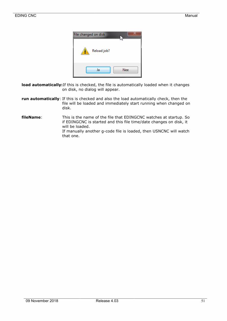
EDING CNC Manual
09 November 2018 Release 4.03 51
load automatically: If this is checked, the file is automatically loaded when it changes
on disk, no dialog will appear.
run automatically: If this is checked and also the load automatically check, then the
file will be loaded and immediately start running when changed on
disk.
fileName: This is the name of the file that EDINGCNC watches at startup. So
if EDINGCNC is started and this file time/date changes on disk, it
will be loaded.
If manually another g-code file is loaded, then USNCNC will watch
that one.
EDING CNC Manual
09 November 2018 Release 4.03 52
2.1.19 Probing Setup
StoreProbePoints: The touch points are stored in a file when this is checked. This is
used for digitizing.
Use Home input 4: If checked home input 4 is used instead of the standard probe
input.
File: The file name for storing the touch points. The file is opened at the
first probe touch en closed when a M30 command is encountered,
usually at the end of the G-Code program.
M95: Using a probe which is fixed on the machine. In this case the probe-
tip will have an offset. For this you can use the M90-M97 function.
With this it is possible to select an offset for Spindle 1 (M90), Spindle
2 (M91), spindle 3 (M92), probe (M95) or camera (M97).
The offset can be calibrated as follows:
1. Take care that M90 is active (1st spindle), if not execute m90 in
MDI.
2. Mark a point on your machine bed and accurately move the tool-
tip to this point.
3. Zero the axes X,Y,Z at this position.
4. Now move the probe tip exactly to this position.
5. Execute in MDI “M95 Q1”.
EDING CNC Manual
09 November 2018 Release 4.03 53
2.1.20 Camera Setup
CameraIndex: Use 0 if you have only one camera, use 1 if you have 2 Cameras and
want to use the 2nd one.
CameraOn: Select Camera if used.
CameraFlip: Flip image vertically
Camera mirror: Mirror camera image horizontally
Rotation: Rotate Camera image [Degrees]
Camera offset calibration, if you have mounted the camera on the
machine the camera will show a different position as the position of
the tool-tip. The difference is Camera offset.
The steps to calibrate this offset are:
1. Take care that M90 is active (1st spindle), if not execute m90 in
MDI.
2. Mark a point on your machine bed and accurately move the tool-
tip to this point. (Tip: drill hole at that point)
3. Zero the axes X,Y,Z at this position.
4. Now move the camera exactly to this position.
5. Execute in MDI “M97 Q1”.
Now when calibrated, you can use M97 to make camera offsets
active.
Tip: Use M97 P1 to position the camera at the tooltip position. Use
M90 P1 to activate and move the main spindle to the work
position.
In the GUI you can also select this by pressing control+F2 in the
graphic menu. Just try and you will see it.
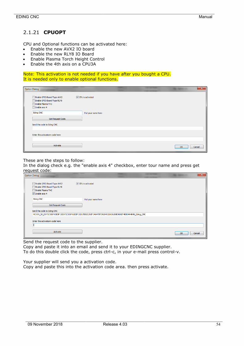
EDING CNC Manual
09 November 2018 Release 4.03 54
2.1.21 CPUOPT
CPU and Optional functions can be activated here:
• Enable the new AVX2 IO board
• Enable the new RLY8 IO Board
• Enable Plasma Torch Height Control
• Enable the 4th axis on a CPU3A
Note: This activation is not needed if you have after you bought a CPU.
It is needed only to enable optional functions.
These are the steps to follow:
In the dialog check e.g. the "enable axis 4" checkbox, enter tour name and press get
request code:
Send the request code to the supplier.
Copy and paste it into an email and send it to your EDINGCNC supplier.
To do this double click the code, press ctrl-c, in your e-mail press control-v.
Your supplier will send you a activation code.
Copy and paste this into the activation code area. then press activate.
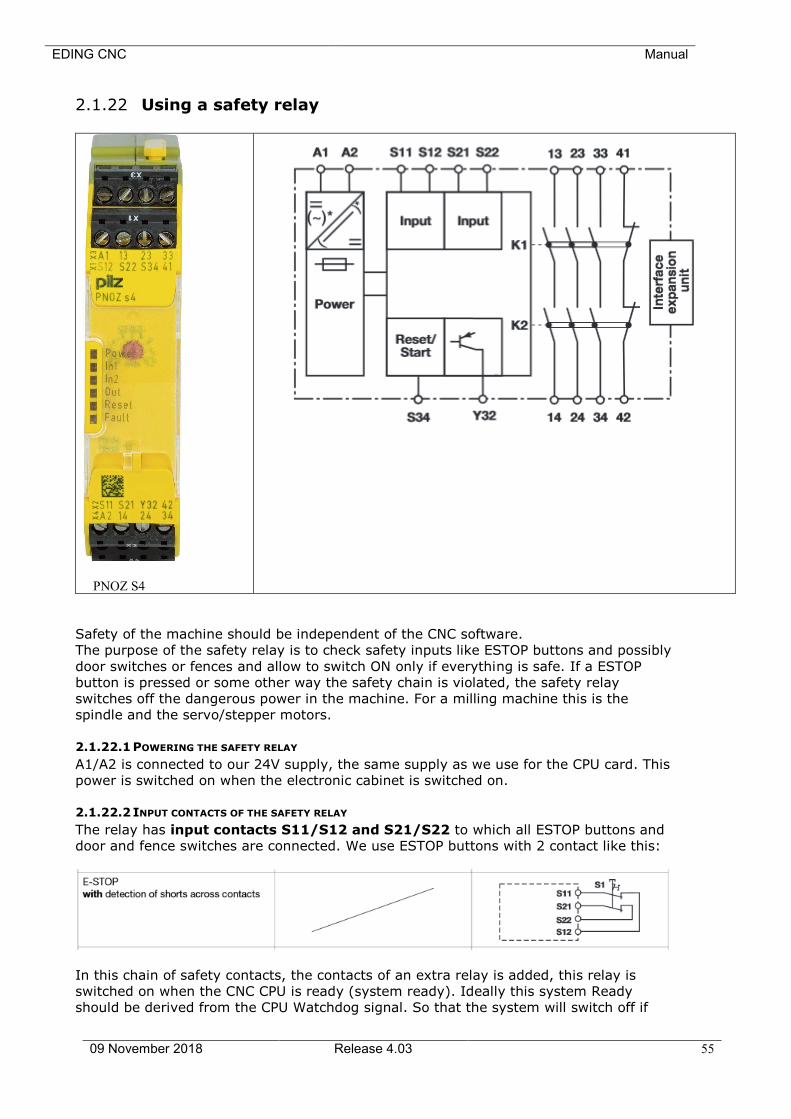
EDING CNC Manual
09 November 2018 Release 4.03 55
2.1.22 Using a safety relay
PNOZ S4
Safety of the machine should be independent of the CNC software.
The purpose of the safety relay is to check safety inputs like ESTOP buttons and possibly
door switches or fences and allow to switch ON only if everything is safe. If a ESTOP
button is pressed or some other way the safety chain is violated, the safety relay
switches off the dangerous power in the machine. For a milling machine this is the
spindle and the servo/stepper motors.
2.1.22.1 POWERING THE SAFETY RELAY
A1/A2 is connected to our 24V supply, the same supply as we use for the CPU card. This
power is switched on when the electronic cabinet is switched on.
2.1.22.2 INPUT CONTACTS OF THE SAFETY RELAY
The relay has input contacts S11/S12 and S21/S22 to which all ESTOP buttons and
door and fence switches are connected. We use ESTOP buttons with 2 contact like this:
In this chain of safety contacts, the contacts of an extra relay is added, this relay is
switched on when the CNC CPU is ready (system ready). Ideally this system Ready
should be derived from the CPU Watchdog signal. So that the system will switch off if
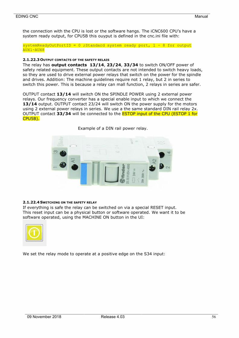
EDING CNC Manual
09 November 2018 Release 4.03 56
the connection with the CPU is lost or the software hangs. The iCNC600 CPU’s have a
system ready output, for CPU5B this ouyput is defined in the cnc.ini file with:
systemReadyOutPortID = 0 ;Standard system ready port, 1 – 8 for output
AUX1-AUX8
2.1.22.3 OUTPUT CONTACTS OF THE SAFETY RELAIS
The relay has output contacts 13/14, 23/24, 33/34 to switch ON/OFF power of
safety related equipment. These output contacts are not intended to switch heavy loads,
so they are used to drive external power relays that switch on the power for the spindle
and drives. Addition: The machine guidelines require not 1 relay, but 2 in series to
switch this power. This is because a relay can mall function, 2 relays in series are safer.
OUTPUT contact 13/14 will switch ON the SPINDLE POWER using 2 external power
relays. Our frequency converter has a special enable input to which we connect the
13/14 output. OUTPUT contact 23/24 will switch ON the power supply for the motors
using 2 external power relays in series. We use a the same standard DIN rail relay 2x.
OUTPUT contact 33/34 will be connected to the ESTOP input of the CPU (ESTOP 1 for
CPU5B).
Example of a DIN rail power relay.
2.1.22.4 SWITCHING ON THE SAFETY RELAY
If everything is safe the relay can be switched on via a special RESET input.
This reset input can be a physical button or software operated. We want it to be
software operated, using the MACHINE ON button in the UI:
We set the relay mode to operate at a positive edge on the S34 input:
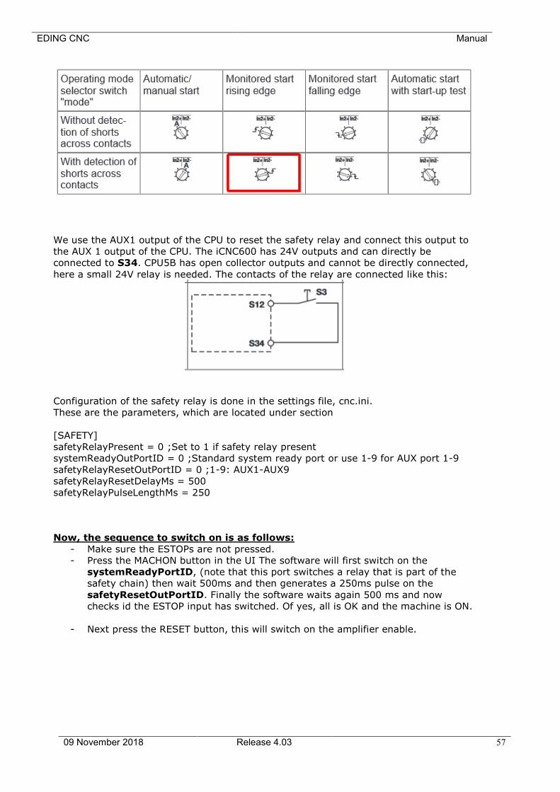
EDING CNC Manual
09 November 2018 Release 4.03 57
We use the AUX1 output of the CPU to reset the safety relay and connect this output to
the AUX 1 output of the CPU. The iCNC600 has 24V outputs and can directly be
connected to S34. CPU5B has open collector outputs and cannot be directly connected,
here a small 24V relay is needed. The contacts of the relay are connected like this:
Configuration of the safety relay is done in the settings file, cnc.ini.
These are the parameters, which are located under section
[SAFETY]
safetyRelayPresent = 0 ;Set to 1 if safety relay present
systemReadyOutPortID = 0 ;Standard system ready port or use 1-9 for AUX port 1-9
safetyRelayResetOutPortID = 0 ;1-9: AUX1-AUX9
safetyRelayResetDelayMs = 500
safetyRelayPulseLengthMs = 250
Now, the sequence to switch on is as follows:
- Make sure the ESTOPs are not pressed.
- Press the MACHON button in the UI The software will first switch on the
systemReadyPortID, (note that this port switches a relay that is part of the
safety chain) then wait 500ms and then generates a 250ms pulse on the
safetyResetOutPortID. Finally the software waits again 500 ms and now
checks id the ESTOP input has switched. Of yes, all is OK and the machine is ON.
- Next press the RESET button, this will switch on the amplifier enable.
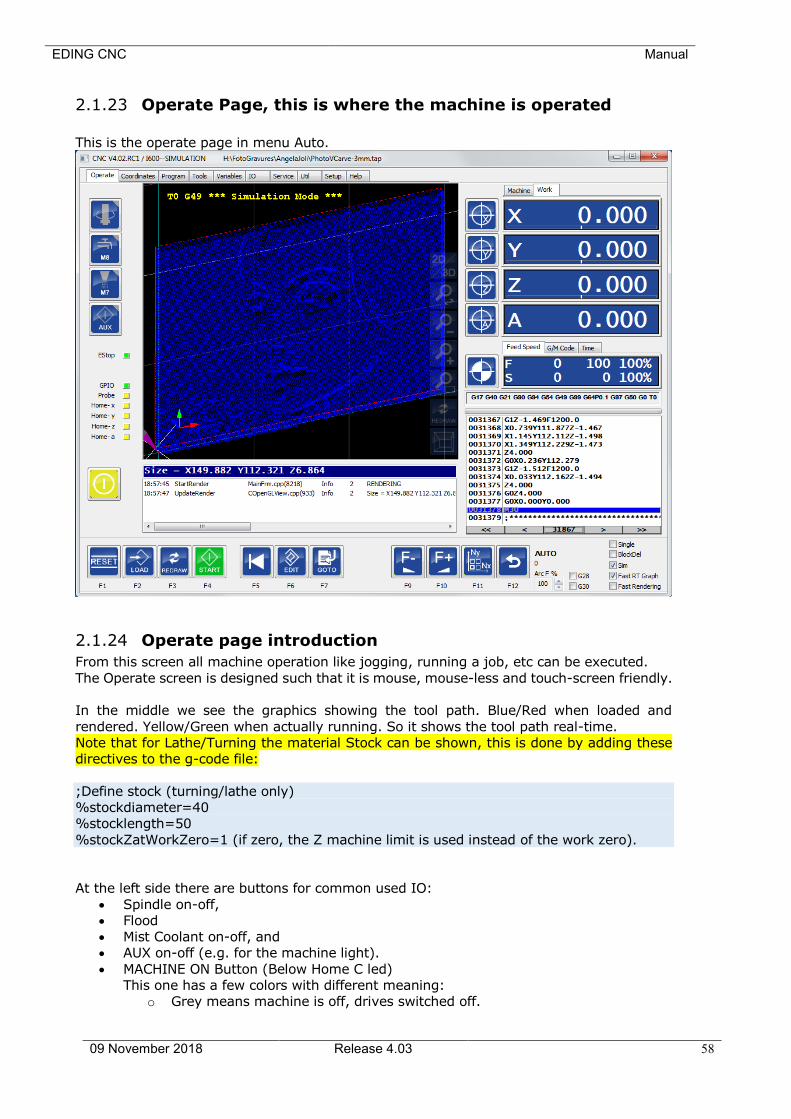
EDING CNC Manual
09 November 2018 Release 4.03 58
2.1.23 Operate Page, this is where the machine is operated
This is the operate page in menu Auto.
2.1.24 Operate page introduction
From this screen all machine operation like jogging, running a job, etc can be executed.
The Operate screen is designed such that it is mouse, mouse-less and touch-screen friendly.
In the middle we see the graphics showing the tool path. Blue/Red when loaded and
rendered. Yellow/Green when actually running. So it shows the tool path real-time.
Note that for Lathe/Turning the material Stock can be shown, this is done by adding these
directives to the g-code file:
;Define stock (turning/lathe only)
%stockdiameter=40
%stocklength=50
%stockZatWorkZero=1 (if zero, the Z machine limit is used instead of the work zero).
At the left side there are buttons for common used IO:
• Spindle on-off,
• Flood
• Mist Coolant on-off, and
• AUX on-off (e.g. for the machine light).
• MACHINE ON Button (Below Home C led)
This one has a few colors with different meaning:
o Grey means machine is off, drives switched off.
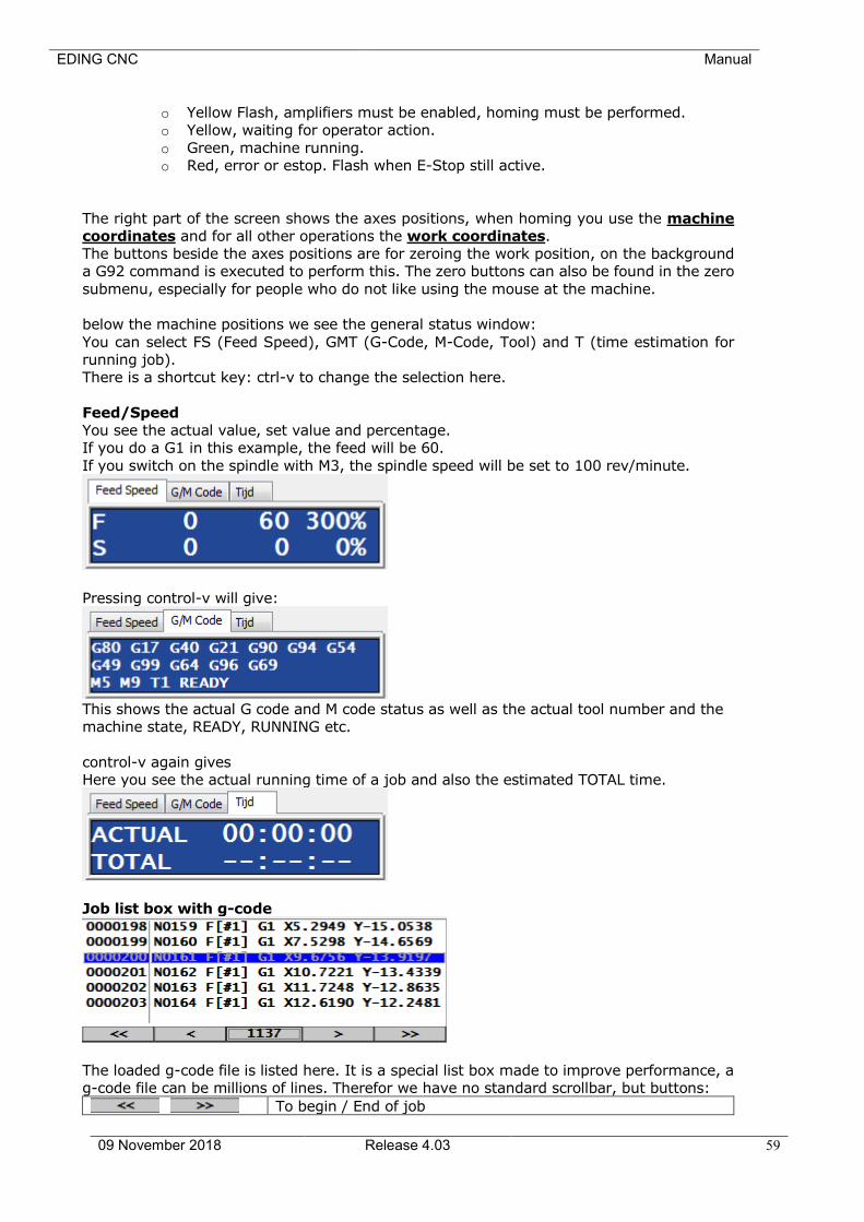
EDING CNC Manual
09 November 2018 Release 4.03 59
o Yellow Flash, amplifiers must be enabled, homing must be performed.
o Yellow, waiting for operator action.
o Green, machine running.
o Red, error or estop. Flash when E-Stop still active.
The right part of the screen shows the axes positions, when homing you use the machine
coordinates and for all other operations the work coordinates.
The buttons beside the axes positions are for zeroing the work position, on the background
a G92 command is executed to perform this. The zero buttons can also be found in the zero
submenu, especially for people who do not like using the mouse at the machine.
below the machine positions we see the general status window:
You can select FS (Feed Speed), GMT (G-Code, M-Code, Tool) and T (time estimation for
running job).
There is a shortcut key: ctrl-v to change the selection here.
Feed/Speed
You see the actual value, set value and percentage.
If you do a G1 in this example, the feed will be 60.
If you switch on the spindle with M3, the spindle speed will be set to 100 rev/minute.
Pressing control-v will give:
This shows the actual G code and M code status as well as the actual tool number and the
machine state, READY, RUNNING etc.
control-v again gives
Here you see the actual running time of a job and also the estimated TOTAL time.
Job list box with g-code
The loaded g-code file is listed here. It is a special list box made to improve performance, a
g-code file can be millions of lines. Therefor we have no standard scrollbar, but buttons:
To begin / End of job
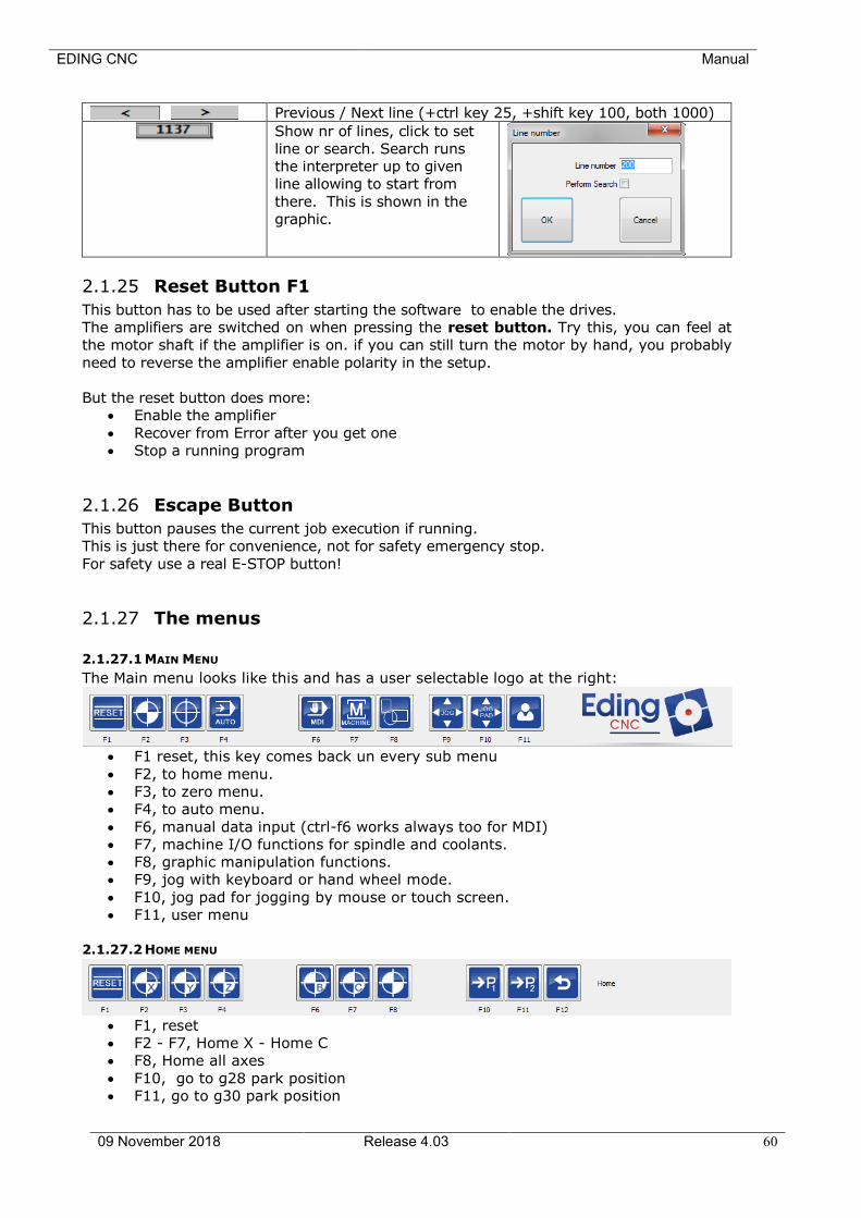
EDING CNC Manual
09 November 2018 Release 4.03 60
Previous / Next line (+ctrl key 25, +shift key 100, both 1000)
Show nr of lines, click to set
line or search. Search runs
the interpreter up to given
line allowing to start from
there. This is shown in the
graphic.
2.1.25 Reset Button F1
This button has to be used after starting the software to enable the drives.
The amplifiers are switched on when pressing the reset button. Try this, you can feel at
the motor shaft if the amplifier is on. if you can still turn the motor by hand, you probably
need to reverse the amplifier enable polarity in the setup.
But the reset button does more:
• Enable the amplifier
• Recover from Error after you get one
• Stop a running program
2.1.26 Escape Button
This button pauses the current job execution if running.
This is just there for convenience, not for safety emergency stop.
For safety use a real E-STOP button!
2.1.27 The menus
2.1.27.1 MAIN MENU
The Main menu looks like this and has a user selectable logo at the right:
• F1 reset, this key comes back un every sub menu
• F2, to home menu.
• F3, to zero menu.
• F4, to auto menu.
• F6, manual data input (ctrl-f6 works always too for MDI)
• F7, machine I/O functions for spindle and coolants.
• F8, graphic manipulation functions.
• F9, jog with keyboard or hand wheel mode.
• F10, jog pad for jogging by mouse or touch screen.
• F11, user menu
2.1.27.2 HOME MENU
• F1, reset
• F2 - F7, Home X - Home C
• F8, Home all axes
• F10, go to g28 park position
• F11, go to g30 park position
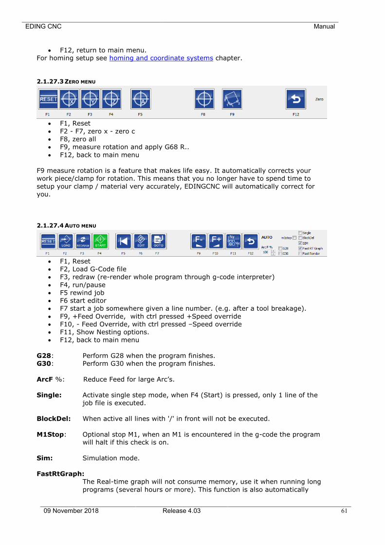
EDING CNC Manual
09 November 2018 Release 4.03 61
• F12, return to main menu.
For homing setup see homing and coordinate systems chapter.
2.1.27.3 ZERO MENU
• F1, Reset
• F2 - F7, zero x - zero c
• F8, zero all
• F9, measure rotation and apply G68 R..
• F12, back to main menu
F9 measure rotation is a feature that makes life easy. It automatically corrects your
work piece/clamp for rotation. This means that you no longer have to spend time to
setup your clamp / material very accurately, EDINGCNC will automatically correct for
you.
2.1.27.4 AUTO MENU
• F1, Reset
• F2, Load G-Code file
• F3, redraw (re-render whole program through g-code interpreter)
• F4, run/pause
• F5 rewind job
• F6 start editor
• F7 start a job somewhere given a line number. (e.g. after a tool breakage).
• F9, +Feed Override, with ctrl pressed +Speed override
• F10, - Feed Override, with ctrl pressed –Speed override
• F11, Show Nesting options.
• F12, back to main menu
G28: Perform G28 when the program finishes.
G30: Perform G30 when the program finishes.
ArcF %: Reduce Feed for large Arc’s.
Single: Activate single step mode, when F4 (Start) is pressed, only 1 line of the
job file is executed.
BlockDel: When active all lines with '/' in front will not be executed.
M1Stop: Optional stop M1, when an M1 is encountered in the g-code the program
will halt if this check is on.
Sim: Simulation mode.
FastRtGraph:
The Real-time graph will not consume memory, use it when running long
programs (several hours or more). This function is also automatically
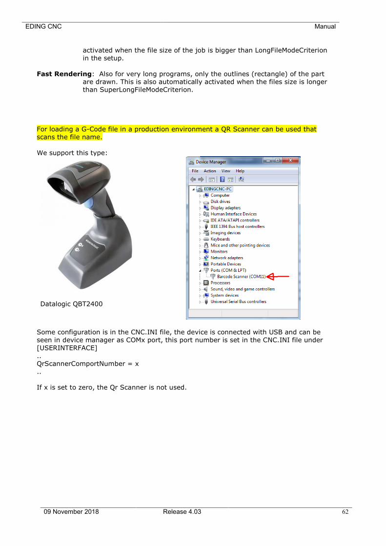
EDING CNC Manual
09 November 2018 Release 4.03 62
activated when the file size of the job is bigger than LongFileModeCriterion
in the setup.
Fast Rendering: Also for very long programs, only the outlines (rectangle) of the part
are drawn. This is also automatically activated when the files size is longer
than SuperLongFileModeCriterion.
For loading a G-Code file in a production environment a QR Scanner can be used that
scans the file name.
We support this type:
Datalogic QBT2400
Some configuration is in the CNC.INI file, the device is connected with USB and can be
seen in device manager as COMx port, this port number is set in the CNC.INI file under
[USERINTERFACE]
..
QrScannerComportNumber = x
..
If x is set to zero, the Qr Scanner is not used.
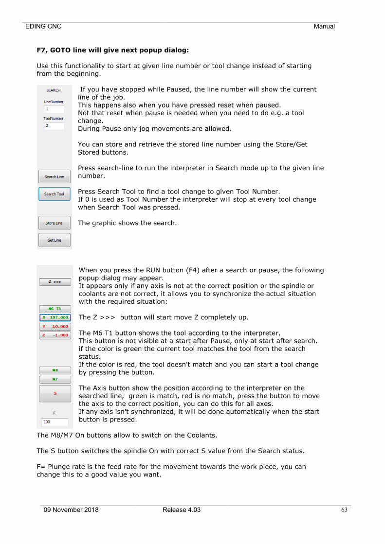
EDING CNC Manual
09 November 2018 Release 4.03 63
F7, GOTO line will give next popup dialog:
Use this functionality to start at given line number or tool change instead of starting
from the beginning.
If you have stopped while Paused, the line number will show the current
line of the job.
This happens also when you have pressed reset when paused.
Not that reset when pause is needed when you need to do e.g. a tool
change.
During Pause only jog movements are allowed.
You can store and retrieve the stored line number using the Store/Get
Stored buttons.
Press search-line to run the interpreter in Search mode up to the given line
number.
Press Search Tool to find a tool change to given Tool Number.
If 0 is used as Tool Number the interpreter will stop at every tool change
when Search Tool was pressed.
The graphic shows the search.
When you press the RUN button (F4) after a search or pause, the following
popup dialog may appear.
It appears only if any axis is not at the correct position or the spindle or
coolants are not correct, it allows you to synchronize the actual situation
with the required situation:
The Z >>> button will start move Z completely up.
The M6 T1 button shows the tool according to the interpreter,
This button is not visible at a start after Pause, only at start after search.
if the color is green the current tool matches the tool from the search
status.
If the color is red, the tool doesn't match and you can start a tool change
by pressing the button.
The Axis button show the position according to the interpreter on the
searched line, green is match, red is no match, press the button to move
the axis to the correct position, you can do this for all axes.
If any axis isn't synchronized, it will be done automatically when the start
button is pressed.
The M8/M7 On buttons allow to switch on the Coolants.
The S button switches the spindle On with correct S value from the Search status.
F= Plunge rate is the feed rate for the movement towards the work piece, you can
change this to a good value you want.
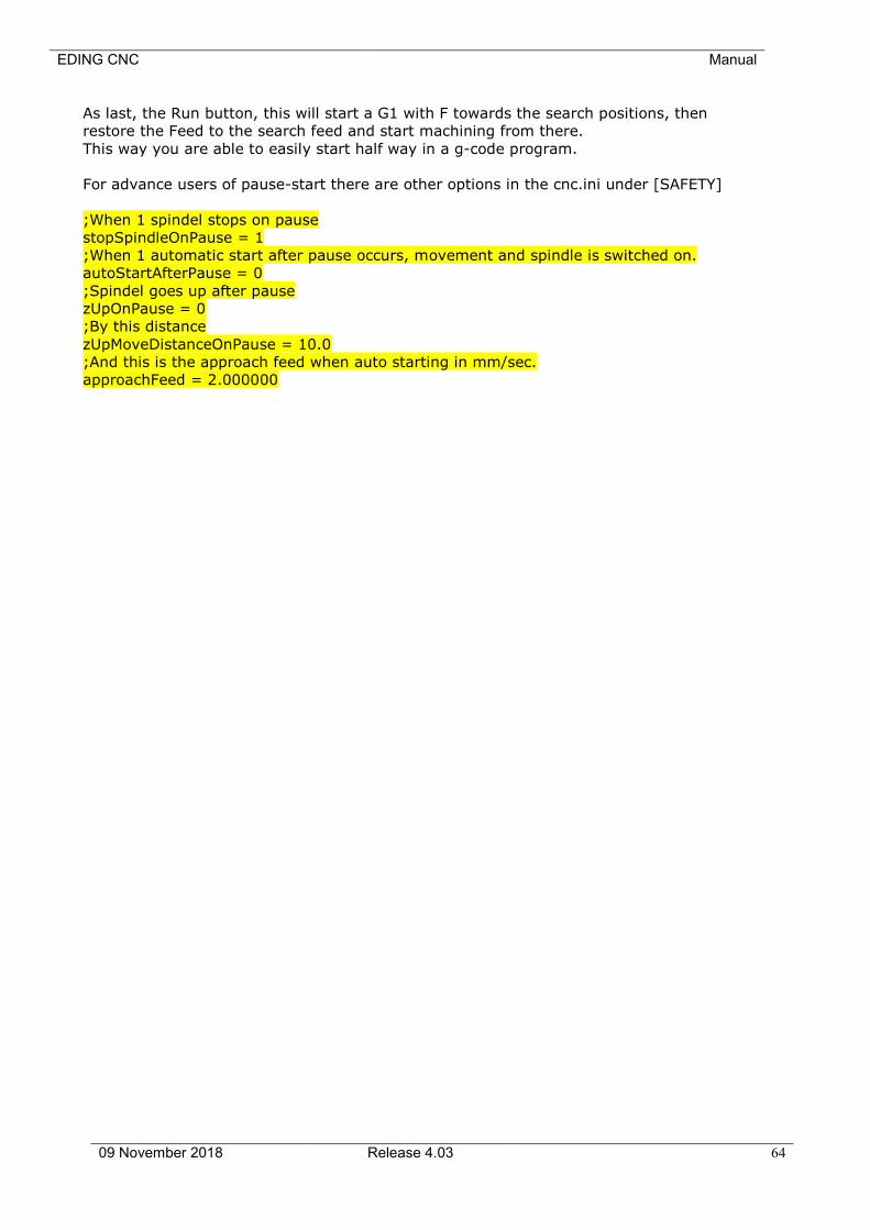
EDING CNC Manual
09 November 2018 Release 4.03 64
As last, the Run button, this will start a G1 with F towards the search positions, then
restore the Feed to the search feed and start machining from there.
This way you are able to easily start half way in a g-code program.
For advance users of pause-start there are other options in the cnc.ini under [SAFETY]
;When 1 spindel stops on pause
stopSpindleOnPause = 1
;When 1 automatic start after pause occurs, movement and spindle is switched on.
autoStartAfterPause = 0
;Spindel goes up after pause
zUpOnPause = 0
;By this distance
zUpMoveDistanceOnPause = 10.0
;And this is the approach feed when auto starting in mm/sec.
approachFeed = 2.000000
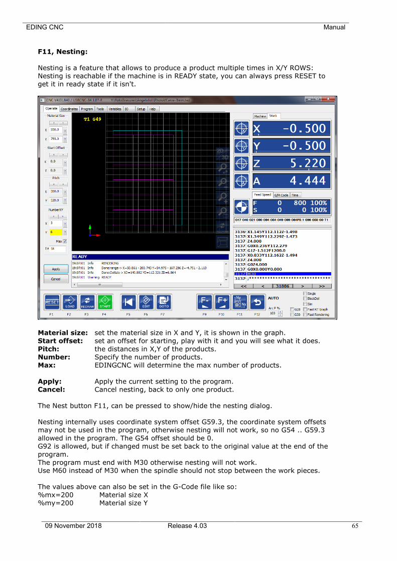
EDING CNC Manual
09 November 2018 Release 4.03 65
F11, Nesting:
Nesting is a feature that allows to produce a product multiple times in X/Y ROWS:
Nesting is reachable if the machine is in READY state, you can always press RESET to
get it in ready state if it isn't.
Material size: set the material size in X and Y, it is shown in the graph.
Start offset: set an offset for starting, play with it and you will see what it does.
Pitch: the distances in X,Y of the products.
Number: Specify the number of products.
Max: EDINGCNC will determine the max number of products.
Apply: Apply the current setting to the program.
Cancel: Cancel nesting, back to only one product.
The Nest button F11, can be pressed to show/hide the nesting dialog.
Nesting internally uses coordinate system offset G59.3, the coordinate system offsets
may not be used in the program, otherwise nesting will not work, so no G54 .. G59.3
allowed in the program. The G54 offset should be 0.
G92 is allowed, but if changed must be set back to the original value at the end of the
program.
The program must end with M30 otherwise nesting will not work.
Use M60 instead of M30 when the spindle should not stop between the work pieces.
The values above can also be set in the G-Code file like so:
%mx=200 Material size X
%my=200 Material size Y
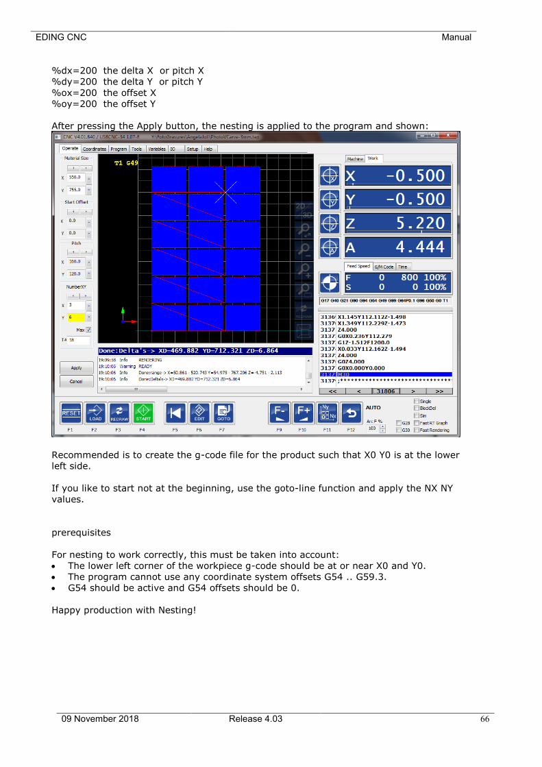
EDING CNC Manual
09 November 2018 Release 4.03 66
%dx=200 the delta X or pitch X
%dy=200 the delta Y or pitch Y
%ox=200 the offset X
%oy=200 the offset Y
After pressing the Apply button, the nesting is applied to the program and shown:
Recommended is to create the g-code file for the product such that X0 Y0 is at the lower
left side.
If you like to start not at the beginning, use the goto-line function and apply the NX NY
values.
prerequisites
For nesting to work correctly, this must be taken into account:
• The lower left corner of the workpiece g-code should be at or near X0 and Y0.
• The program cannot use any coordinate system offsets G54 .. G59.3.
• G54 should be active and G54 offsets should be 0.
Happy production with Nesting!
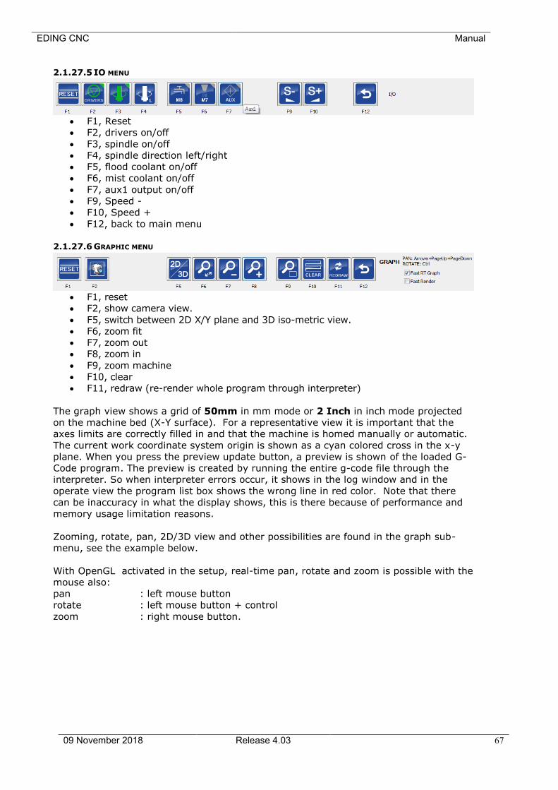
EDING CNC Manual
09 November 2018 Release 4.03 67
2.1.27.5 IO MENU
• F1, Reset
• F2, drivers on/off
• F3, spindle on/off
• F4, spindle direction left/right
• F5, flood coolant on/off
• F6, mist coolant on/off
• F7, aux1 output on/off
• F9, Speed -
• F10, Speed +
• F12, back to main menu
2.1.27.6 GRAPHIC MENU
• F1, reset
• F2, show camera view.
• F5, switch between 2D X/Y plane and 3D iso-metric view.
• F6, zoom fit
• F7, zoom out
• F8, zoom in
• F9, zoom machine
• F10, clear
• F11, redraw (re-render whole program through interpreter)
The graph view shows a grid of 50mm in mm mode or 2 Inch in inch mode projected
on the machine bed (X-Y surface). For a representative view it is important that the
axes limits are correctly filled in and that the machine is homed manually or automatic.
The current work coordinate system origin is shown as a cyan colored cross in the x-y
plane. When you press the preview update button, a preview is shown of the loaded G-
Code program. The preview is created by running the entire g-code file through the
interpreter. So when interpreter errors occur, it shows in the log window and in the
operate view the program list box shows the wrong line in red color. Note that there
can be inaccuracy in what the display shows, this is there because of performance and
memory usage limitation reasons.
Zooming, rotate, pan, 2D/3D view and other possibilities are found in the graph sub-
menu, see the example below.
With OpenGL activated in the setup, real-time pan, rotate and zoom is possible with the
mouse also:
pan : left mouse button
rotate : left mouse button + control
zoom : right mouse button.
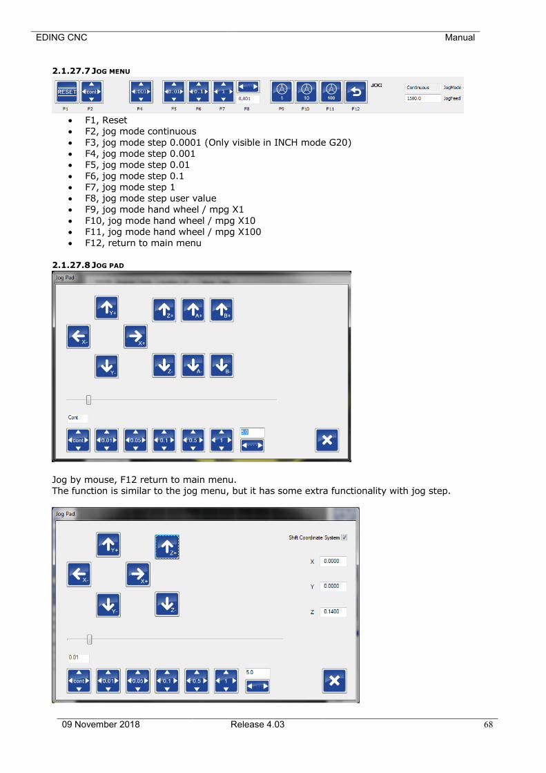
EDING CNC Manual
09 November 2018 Release 4.03 68
2.1.27.7 JOG MENU
• F1, Reset
• F2, jog mode continuous
• F3, jog mode step 0.0001 (Only visible in INCH mode G20)
• F4, jog mode step 0.001
• F5, jog mode step 0.01
• F6, jog mode step 0.1
• F7, jog mode step 1
• F8, jog mode step user value
• F9, jog mode hand wheel / mpg X1
• F10, jog mode hand wheel / mpg X10
• F11, jog mode hand wheel / mpg X100
• F12, return to main menu
2.1.27.8 JOG PAD
Jog by mouse, F12 return to main menu.
The function is similar to the jog menu, but it has some extra functionality with jog step.

EDING CNC Manual
09 November 2018 Release 4.03 69
When “Shift Coordinate System” is checked, jog-step functions as normal, the axes move
one step at a time. The work position however remains the same. This is accomplished by
modifying the active G92 offset. It is useful when e.g. during engraving you want to run the
G-Code program again, but a little deeper in Z. E.g. you want to run the program 0.1 mm
deeper, select jog step 0.1 and check “shift coordinate system” . Now press de arrow down
button to move Z 0.1 mm down. Notice that the axis moves down but that the position
remains the same. When you run your engraving program again the engraving will be 0.1
mm deeper into the material.
This option is also very handy during turning. Your program has run and you measure the
work piece and see its diameter is still a bit too big. So now use the –X button to compensate
the diameter. Run the program again and your work-piece diameter will be correct.
The amount of shift is shown at the right side. To reset the value to 0, which has no influence
on the active offset nor machine position, uncheck, and then check “shift coordinate system”.
2.1.27.9 USER MENU
• F1, Reset
• F2, Zero the Z coordinate using a flexible tool setter positioned on top of the material,
see ZERO TOOL MACRO chapter.
• F3, measure the tool length and put the length in the tool-table using a fixed tool
setter, see TOOL MEASUREMENT MACRO chapter.
• F4 - F11, user function user_3 .. user_10, user defined functions in macro.cnc
• F12, return to main menu.
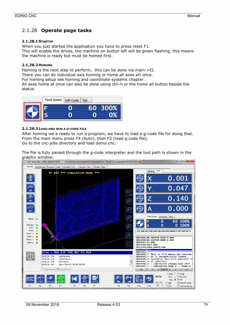
EDING CNC Manual
09 November 2018 Release 4.03 70
2.1.28 Operate page tasks
2.1.28.1 STARTUP
When you just started the application you have to press reset F1.
This will enable the drives, the machine on button left will be green flashing, this means
the machine is ready but must be homed first.
2.1.28.2 HOMING
Homing is the next step to perform, this can be done via main->f2.
There you can do individual axis homing or home all axes art once.
For homing setup see homing and coordinate systems chapter.
All axes home at once can also be done using ctrl-h or the home all button beside the
status:
2.1.28.3 LOAD AND RUN A G-CODE FILE
After homing we a ready to run a program, we have to load a g-code file for doing that.
From the main menu press F4 (Auto), then F2 (load g-code file).
Go to the cnc-jobs directory and load demo.cnc.
The file is fully parsed through the g-code interpreter and the tool path is shown in the
graphic window:
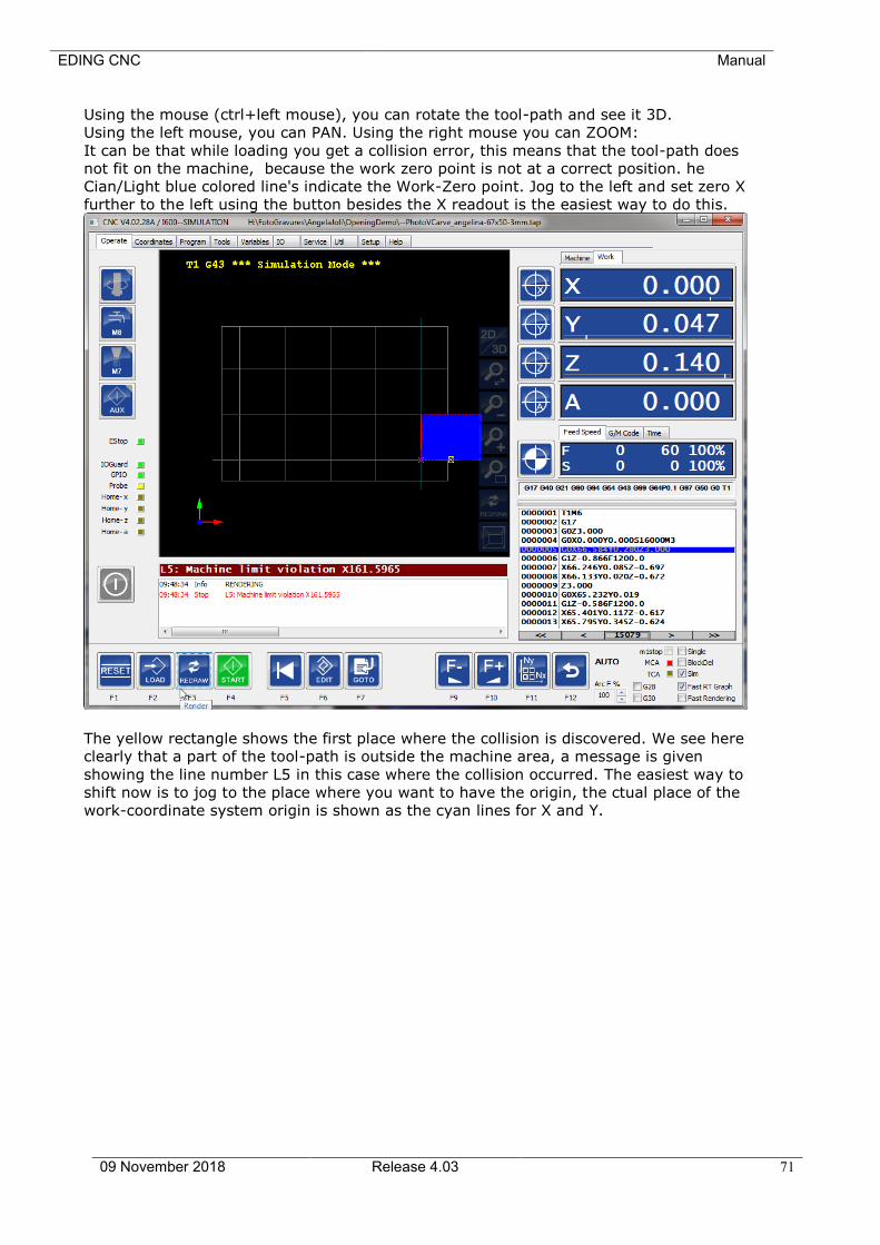
EDING CNC Manual
09 November 2018 Release 4.03 71
Using the mouse (ctrl+left mouse), you can rotate the tool-path and see it 3D.
Using the left mouse, you can PAN. Using the right mouse you can ZOOM:
It can be that while loading you get a collision error, this means that the tool-path does
not fit on the machine, because the work zero point is not at a correct position. he
Cian/Light blue colored line's indicate the Work-Zero point. Jog to the left and set zero X
further to the left using the button besides the X readout is the easiest way to do this.
The yellow rectangle shows the first place where the collision is discovered. We see here
clearly that a part of the tool-path is outside the machine area, a message is given
showing the line number L5 in this case where the collision occurred. The easiest way to
shift now is to jog to the place where you want to have the origin, the ctual place of the
work-coordinate system origin is shown as the cyan lines for X and Y.
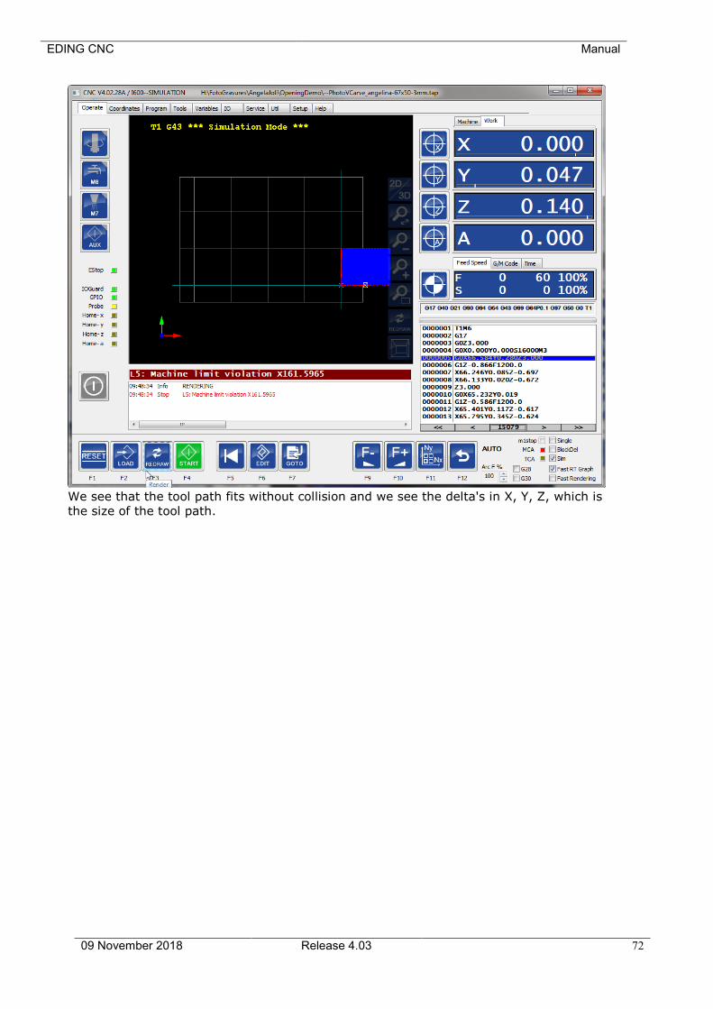
EDING CNC Manual
09 November 2018 Release 4.03 72
We see that the tool path fits without collision and we see the delta's in X, Y, Z, which is
the size of the tool path.
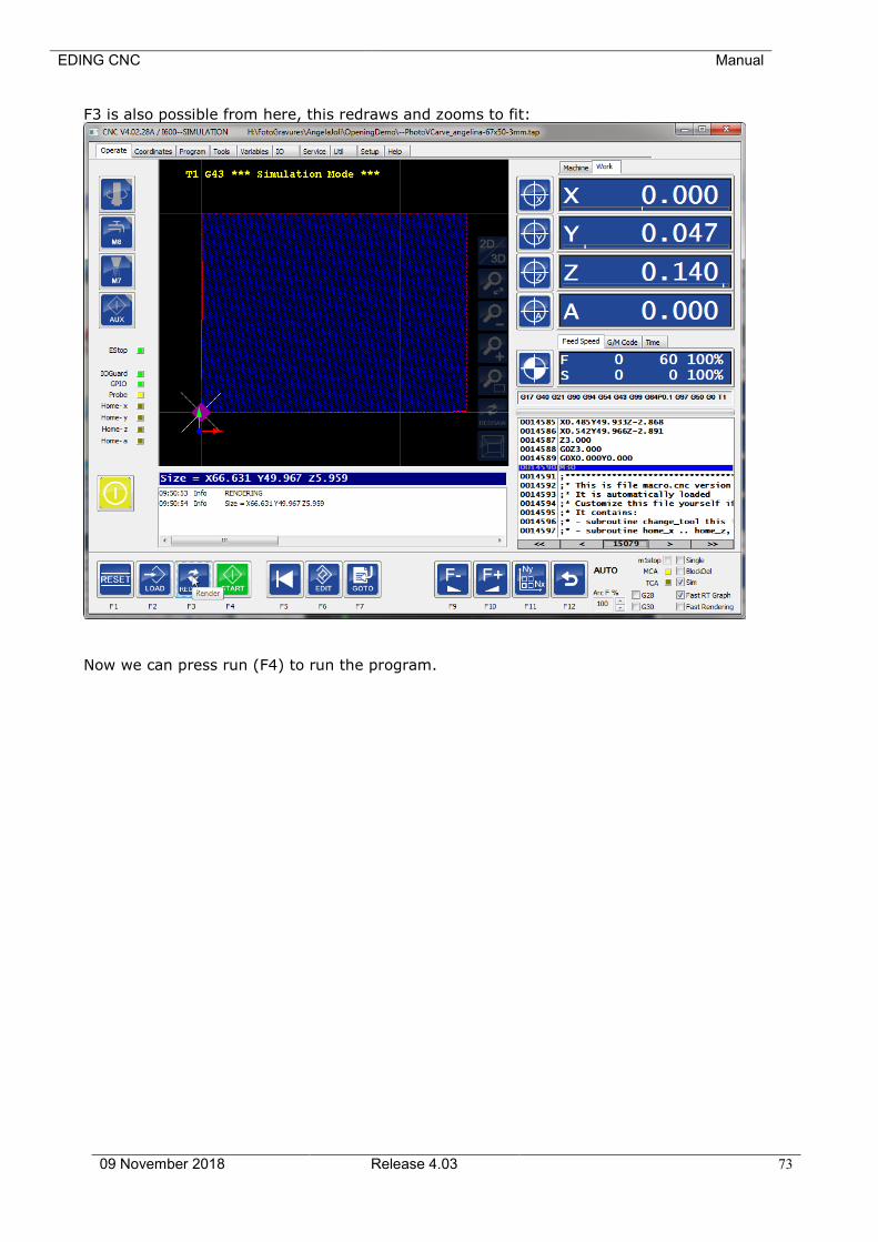
EDING CNC Manual
09 November 2018 Release 4.03 73
F3 is also possible from here, this redraws and zooms to fit:
Now we can press run (F4) to run the program.

EDING CNC Manual
09 November 2018 Release 4.03 74
We have no automatic tool changer, so the program stops when a tool change is
encountered asking us to put in the tool.:
The tool is already in, so we press F4 again, the program will continue and our machine
is working.
We see the tool path being drawn real-time on the screen:
If you check the G28 or G30 checkbox, then the machine will return to its G28 or G30
position when the job is done. You can specify those positions in the variables tab.
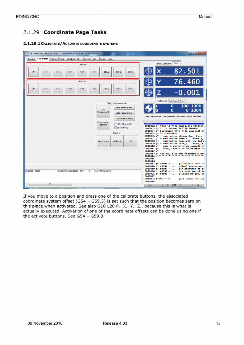
EDING CNC Manual
09 November 2018 Release 4.03 75
2.1.29 Coordinate Page Tasks
2.1.29.1 CALIBRATE/ACTIVATE COORDINATE SYSTEMS
If you move to a position and press one of the calibrate buttons, the associated
coordinate system offset (G54 – G59.3) is set such that the position becomes zero on
this place when activated. See also G10 L20 P.. X.. Y.. Z.. because this is what is
actually executed. Activation of one of the coordinate offsets can be done using one if
the activate buttons, See G54 – G59.3.
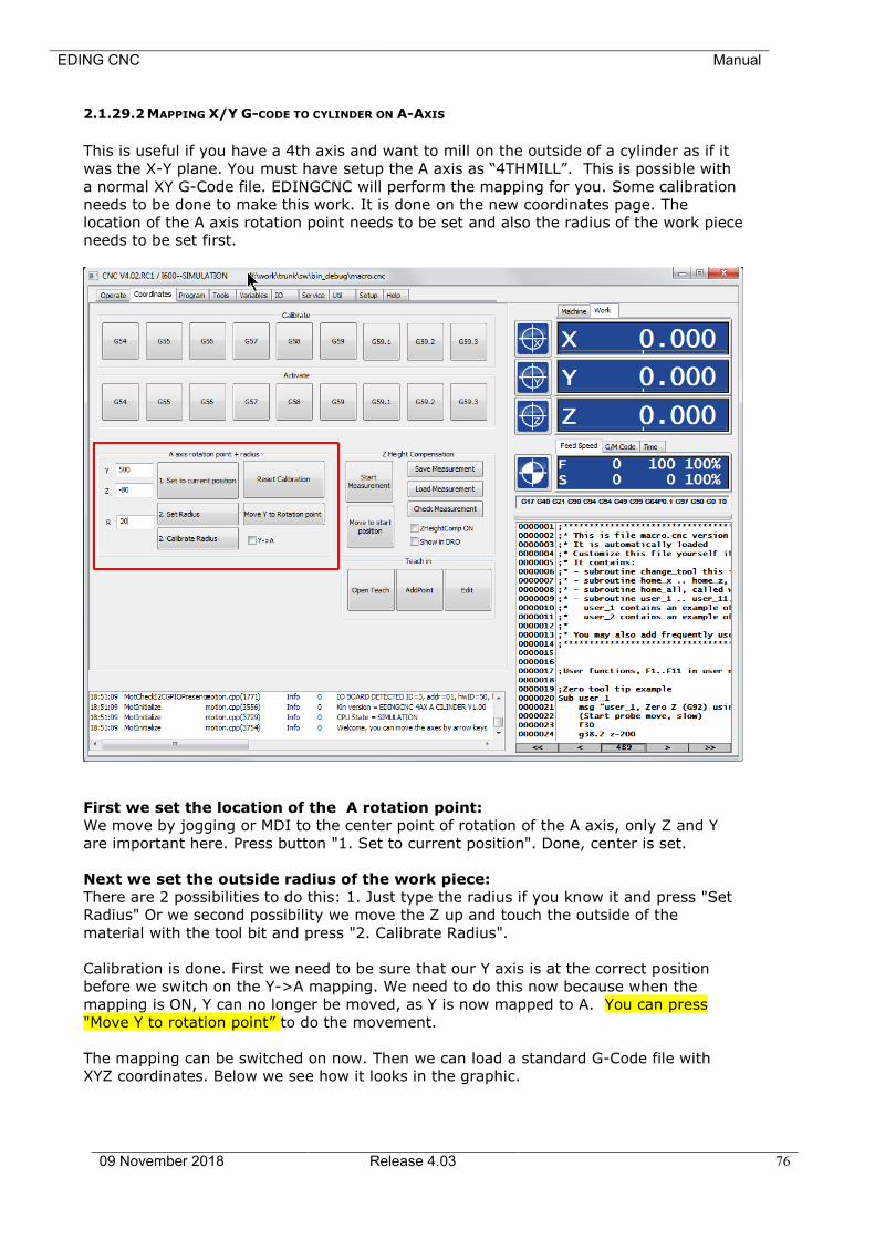
EDING CNC Manual
09 November 2018 Release 4.03 76
2.1.29.2 MAPPING X/Y G-CODE TO CYLINDER ON A-AXIS
This is useful if you have a 4th axis and want to mill on the outside of a cylinder as if it
was the X-Y plane. You must have setup the A axis as “4THMILL”. This is possible with
a normal XY G-Code file. EDINGCNC will perform the mapping for you. Some calibration
needs to be done to make this work. It is done on the new coordinates page. The
location of the A axis rotation point needs to be set and also the radius of the work piece
needs to be set first.
First we set the location of the A rotation point:
We move by jogging or MDI to the center point of rotation of the A axis, only Z and Y
are important here. Press button "1. Set to current position". Done, center is set.
Next we set the outside radius of the work piece:
There are 2 possibilities to do this: 1. Just type the radius if you know it and press "Set
Radius" Or we second possibility we move the Z up and touch the outside of the
material with the tool bit and press "2. Calibrate Radius".
Calibration is done. First we need to be sure that our Y axis is at the correct position
before we switch on the Y->A mapping. We need to do this now because when the
mapping is ON, Y can no longer be moved, as Y is now mapped to A. You can press
"Move Y to rotation point” to do the movement.
The mapping can be switched on now. Then we can load a standard G-Code file with
XYZ coordinates. Below we see how it looks in the graphic.
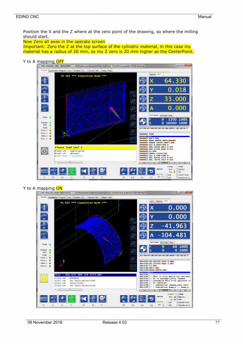
EDING CNC Manual
09 November 2018 Release 4.03 77
Position the X and the Z where at the zero point of the drawing, so where the milling
should start.
Now Zero all axes in the operate screen
Important: Zero the Z at the top surface of the cylindric material, in this case my
material has a radius of 20 mm, so my Z zero is 20 mm higher as the CenterPoint.
Y to A mapping OFF
Y to A mapping ON
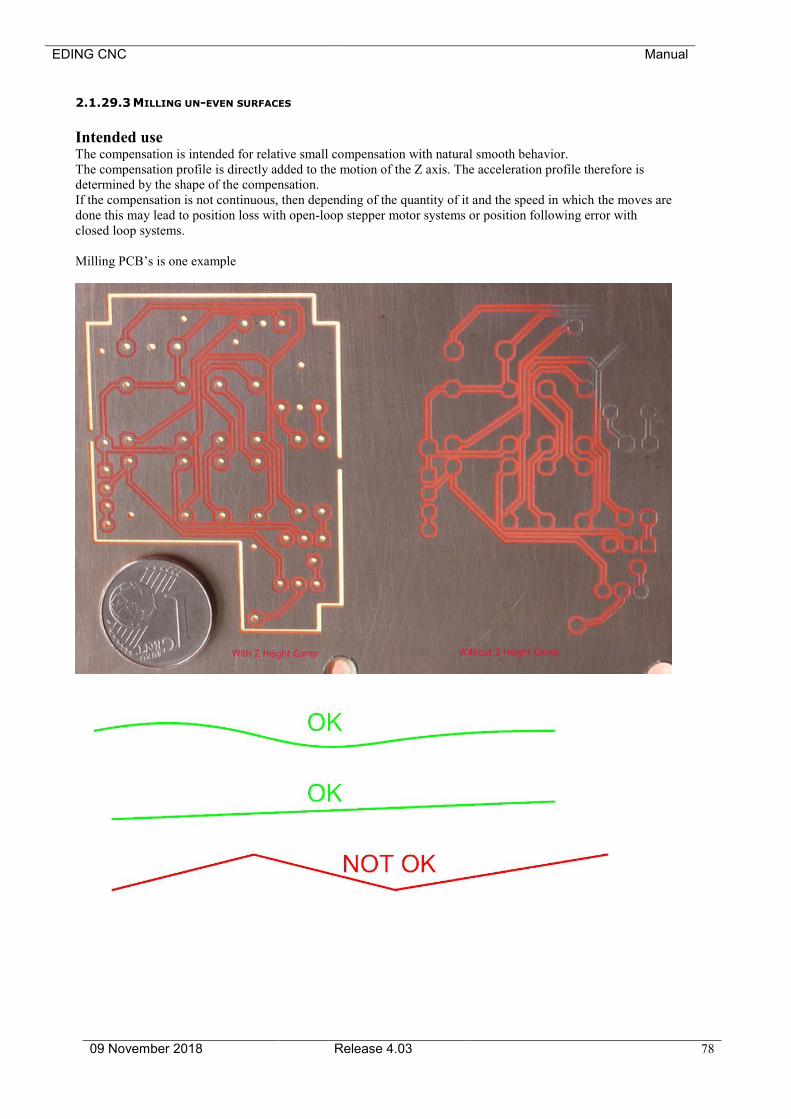
EDING CNC Manual
09 November 2018 Release 4.03 78
2.1.29.3 MILLING UN-EVEN SURFACES
Intended use The compensation is intended for relative small compensation with natural smooth behavior.
The compensation profile is directly added to the motion of the Z axis. The acceleration profile therefore is
determined by the shape of the compensation.
If the compensation is not continuous, then depending of the quantity of it and the speed in which the moves are
done this may lead to position loss with open-loop stepper motor systems or position following error with
closed loop systems.
Milling PCB’s is one example

EDING CNC Manual
09 November 2018 Release 4.03 79
The Coordinates TAB will contain the new functionality:
“Start measurement”
will popup an interpreter dialog for the automatics measurement using a toch probe. It is explaned on next page
“Move to start position”
will move X and Y to the first measured position, there where the compensation is zero.
“Save measurement”
Will open a file-save dialog and allows to save the mesurement data.
“Load measurement”
Shows a file-open dialog to load existing measurement data.
“Check measurement”
Wil show some statics of the measured data, the max and minimum correction values and at which place they
are.
“ZheightComp ON”
Wil switch the compensation ON/OFF.
It will be shown in the position read out, the compensation value is shown above the normal work position of Z.
Now you can do normal XY engraving and while the Z is compensated using the measurement values.

EDING CNC Manual
09 November 2018 Release 4.03 80
Starting the measurement
You specify the number of measurement in X and Y.
The height to which the probe should move to when going to the next point.
The minimum Z value to which the probe should move to during the measurement
(G38.2).
The size of the grid, distance between the measuring points.
And the feed for the down movement during G38.2. All other moves use G0 for highest
speed.
The measurement starts at WORK X0 Y0. maxZ and Min Z are also WORK coordinates.
The measurement data itself is in motor coordinates, so after the measurement you can
freely zero anywhere else on the work piece.
This is the subroutine to be added in the standard macro.cnc for this purpose.
If you have a self-modified macro.cnc, you can copy from default_macro.cnc to your
own macro.cnc
sub zhcmgrid
;;;;;;;;;;;;;
;probe scanning routine for eneven surface milling
;scanning starts at x=0, y=0
if [#4100 == 0]
#4100 = 10 ;nx
#4101 = 5 ;ny
#4102 = 40 ;max z
#4103 = 10 ;min z
#4104 = 1.0 ;step size
#4105 = 100 ;probing feed
endif
#110 = 0 ;Actual nx
#111 = 0 ;Actual ny
#112 = 0 ;Missed measurements counter
#113 = 0 ;Number of points added
#114 = 1 ;0: odd x row, 1: even xrow
;Dialog
dlgmsg "gridMeas" "nx" 4100 "ny" 4101 "maxZ" 4102 "minZ" 4103 "gridSize" 4104 "Feed" 4105
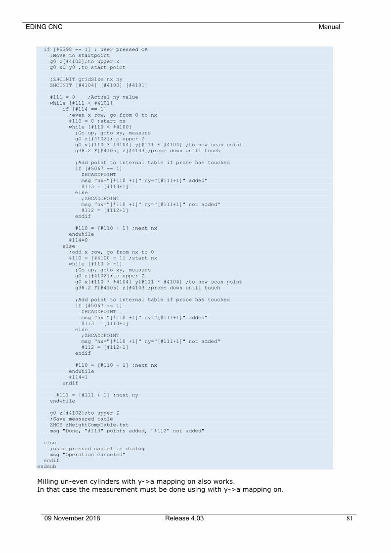
EDING CNC Manual
09 November 2018 Release 4.03 81
if [#5398 == 1] ; user pressed OK
;Move to startpoint
g0 z[#4102];to upper Z
g0 x0 y0 ;to start point
;ZHCINIT gridSize nx ny
ZHCINIT [#4104] [#4100] [#4101]
#111 = 0 ;Actual ny value
while [#111 < #4101]
if [#114 == 1]
;even x row, go from 0 to nx
#110 = 0 ;start nx
while [#110 < #4100]
;Go up, goto xy, measure
g0 z[#4102];to upper Z
g0 x[#110 * #4104] y[#111 * #4104] ;to new scan point
g38.2 F[#4105] z[#4103];probe down until touch
;Add point to internal table if probe has touched
if [#5067 == 1]
ZHCADDPOINT
msg "nx="[#110 +1]" ny="[#111+1]" added"
#113 = [#113+1]
else
;ZHCADDPOINT
msg "nx="[#110 +1]" ny="[#111+1]" not added"
#112 = [#112+1]
endif
#110 = [#110 + 1] ;next nx
endwhile
#114=0
else
;odd x row, go from nx to 0
#110 = [#4100 - 1] ;start nx
while [#110 > -1]
;Go up, goto xy, measure
g0 z[#4102];to upper Z
g0 x[#110 * #4104] y[#111 * #4104] ;to new scan point
g38.2 F[#4105] z[#4103];probe down until touch
;Add point to internal table if probe has touched
if [#5067 == 1]
ZHCADDPOINT
msg "nx="[#110 +1]" ny="[#111+1]" added"
#113 = [#113+1]
else
;ZHCADDPOINT
msg "nx="[#110 +1]" ny="[#111+1]" not added"
#112 = [#112+1]
endif
#110 = [#110 - 1] ;next nx
endwhile
#114=1
endif
#111 = [#111 + 1] ;next ny
endwhile
g0 z[#4102];to upper Z
;Save measured table
ZHCS zHeightCompTable.txt
msg "Done, "#113" points added, "#112" not added"
else
;user pressed cancel in dialog
msg "Operation canceled"
endif
endsub
Milling un-even cylinders with y->a mapping on also works.
In that case the measurement must be done using with y->a mapping on.
EDING CNC Manual
09 November 2018 Release 4.03 82
The compensation works only in the measured range. So of the mapping is measured
between 0-360 degrees for A, it will not compensate for e.g. 370 degrees.
The Z height compensation interpreter commands
For your own use if you want to customize the working:
ZHCINIT <grid size in mm> <number of points in X> <number of points in Y>
This is the first command required before starting a measurement, it will reserve the
correct amount of memory to store the measured points.
ZHCINITEX <grid sizeX> <grid sizeY> <n of points in X> <n of points in Y>
Instead of ZHCINIT you can use ZHCINITEX.
The difference with ZHCINIT is that this allows different grid sizes for X and Y.
Using G38.2 will do the actual measurement.
ZHCADDPOINT will add the last measured point to the data.
ZHCS <fileName> will store the data to a file.
ZHCL <fileName> will load the data from a file.
ZHC [ON | OFF] will switch the compensation on.
#5151 contains 1 if ZHC is ON and 0 if OFF. This can be used for run time checks if the
compensation is on. In case of tool change, you will probably want to switch it off and
switch it back ON after the tool change.
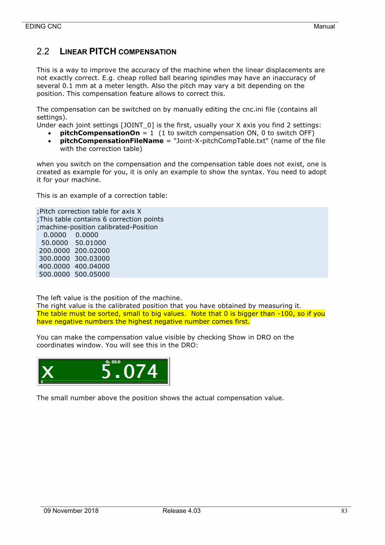
EDING CNC Manual
09 November 2018 Release 4.03 83
2.2 LINEAR PITCH COMPENSATION
This is a way to improve the accuracy of the machine when the linear displacements are
not exactly correct. E.g. cheap rolled ball bearing spindles may have an inaccuracy of
several 0.1 mm at a meter length. Also the pitch may vary a bit depending on the
position. This compensation feature allows to correct this.
The compensation can be switched on by manually editing the cnc.ini file (contains all
settings).
Under each joint settings [JOINT_0] is the first, usually your X axis you find 2 settings:
• pitchCompensationOn = 1 (1 to switch compensation ON, 0 to switch OFF)
• pitchCompensationFileName = "Joint-X-pitchCompTable.txt" (name of the file
with the correction table)
when you switch on the compensation and the compensation table does not exist, one is
created as example for you, it is only an example to show the syntax. You need to adopt
it for your machine.
This is an example of a correction table:
;Pitch correction table for axis X
;This table contains 6 correction points
;machine-position calibrated-Position
0.0000 0.0000
50.0000 50.01000
200.0000 200.02000
300.0000 300.03000
400.0000 400.04000
500.0000 500.05000
The left value is the position of the machine.
The right value is the calibrated position that you have obtained by measuring it.
The table must be sorted, small to big values. Note that 0 is bigger than -100, so if you
have negative numbers the highest negative number comes first.
You can make the compensation value visible by checking Show in DRO on the
coordinates window. You will see this in the DRO:
The small number above the position shows the actual compensation value.
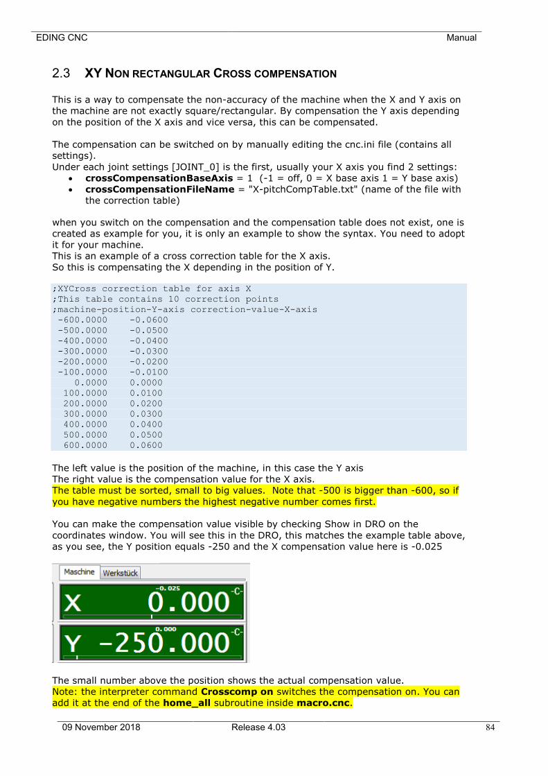
EDING CNC Manual
09 November 2018 Release 4.03 84
2.3 XY NON RECTANGULAR CROSS COMPENSATION
This is a way to compensate the non-accuracy of the machine when the X and Y axis on
the machine are not exactly square/rectangular. By compensation the Y axis depending
on the position of the X axis and vice versa, this can be compensated.
The compensation can be switched on by manually editing the cnc.ini file (contains all
settings).
Under each joint settings [JOINT_0] is the first, usually your X axis you find 2 settings:
• crossCompensationBaseAxis = 1 (-1 = off, 0 = X base axis 1 = Y base axis)
• crossCompensationFileName = "X-pitchCompTable.txt" (name of the file with
the correction table)
when you switch on the compensation and the compensation table does not exist, one is
created as example for you, it is only an example to show the syntax. You need to adopt
it for your machine.
This is an example of a cross correction table for the X axis.
So this is compensating the X depending in the position of Y.
;XYCross correction table for axis X
;This table contains 10 correction points
;machine-position-Y-axis correction-value-X-axis
-600.0000 -0.0600
-500.0000 -0.0500
-400.0000 -0.0400
-300.0000 -0.0300
-200.0000 -0.0200
-100.0000 -0.0100
0.0000 0.0000
100.0000 0.0100
200.0000 0.0200
300.0000 0.0300
400.0000 0.0400
500.0000 0.0500
600.0000 0.0600
The left value is the position of the machine, in this case the Y axis
The right value is the compensation value for the X axis.
The table must be sorted, small to big values. Note that -500 is bigger than -600, so if
you have negative numbers the highest negative number comes first.
You can make the compensation value visible by checking Show in DRO on the
coordinates window. You will see this in the DRO, this matches the example table above,
as you see, the Y position equals -250 and the X compensation value here is -0.025
The small number above the position shows the actual compensation value.
Note: the interpreter command Crosscomp on switches the compensation on. You can
add it at the end of the home_all subroutine inside macro.cnc.

EDING CNC Manual
09 November 2018 Release 4.03 85
2.4 SPEED-PWM COMPENSATION The speed for a spindle is controlled by the PWM output.
The PWM is converted to an analogue signal which is fed to the VFD (Variable frequency
drive). There are often non linearity’s involved.
This cause that the programmed speed and the real speed does not match correctly.
This software feature allows to compensate this.
The compensation can be switched on by manually editing the cnc.ini file (contains all
settings).
Under each spindle settings [SPINDLE_0] is the first, usually your main spindle (M90)
axis you find 2 settings:
• pwmCompensationOn= 1 (1 to switch compensation ON, 0 to switch OFF)
• pwmCompensationFileName= " Spindle-0-pwmCompTable.txt" (name of the
file with the correction table)
when you switch on the compensation and the compensation table does not exist, one is
created as example for you, it is only an example to show the syntax. You need to adopt
it for your machine.
This is an example of a correction table:
;Speed PWM calibration table for spindle 0
;This table contains 15 correction points
;Speed PWM Percentage
0.00 0.00
720.00 8.00
1146.00 10.00
3468.00 20.00
5832.00 30.00
6000.00 31.00
8280.00 40.00
10740.00 50.00
13260.00 60.00
15780.00 70.00
18000.00 79.00
18120.00 80.00
21060.00 90.00
24000.00 100.00
The number on the left side is the Spindle Speed and on the right side the required PWM
value 0-100%.
You can see the PWM value in the IO screen and you can make it also visible at the
main screen instead of the programmed speed.
The setting is under [USERINTERFACE]
;0=programmed speed, 1=PWM value, 2=analogIn1, 3=analogIn2, 4=analogIn3
• showInProgSpeed = 1
• showInProgSpeedAnaMulFactor = 1.0000

EDING CNC Manual
09 November 2018 Release 4.03 86
As you can see you can also choose to show an analogue input with a multiplication
factor, this can be used when the spindle has a power used signal.
EDING CNC Manual
09 November 2018 Release 4.03 87
2.5 AUTOMATIC VACUUM SECTIONS
Large machines may have several vacuum sections which can be switched on
individually.
EdingCNC supports up to 64 vacuum sections.
During loading/rendering of the g-code file, the software automatically detects the
sections on which the operation stakes place.
These are special interpreter commands for the vacuum:
Vacuum ON: Switches on all vacuum sections and related pumps.
Vacuum OFF: Switches off the vacuum sections and pumps.
Vacuum ADD: Add section under current position.
Vacuum CLEAR: Clear all used sections.
The configuration of this is done by editing the CNC.INI file.
We will add this later in the GUI when our new GUI development is ready.
The first time, there will be only this in the CNC.INI: [VACUUMBED]
automaticMode = 0
numberOfSections = 0
Note always close the software when making changes in the CNC.INI file.
Then set the number of sections required.
Start the software, then close the software, now the parameters for the sections
appear: [VACUUMBED]
automaticMode = 1
numberOfSections = 2
section_1_OutputID = 0 ;0: NONE, 1-10: AUX1-AUX10, 101-108 GPIO CARD 1
OUPUT 1-8
sectionPump_1_OutputID = 0 ;0: NONE, 1-10: AUX1-AUX10, 101-108 GPIO CARD 1
OUPUT 1-8
section_1_XPosition = 0.000000
section_1_YPosition = 0.000000
section_1_XWidth = 0.000000
section_1_YWidth = 0.000000
section_2_OutputID = 0 ;0: NONE, 1-10: AUX1-AUX10, 101-108 GPIO CARD 1
OUPUT 1-8
sectionPump_2_OutputID = 0 ;0: NONE, 1-10: AUX1-AUX10, 101-108 GPIO CARD 1
OUPUT 1-8
section_2_XPosition = 0.000000
section_2_YPosition = 0.000000
section_2_XWidth = 0.000000
section_2_YWidth = 0.000000
You will need to specify the location and size of each section in machine coordinates.
Then each section has 2 associated outputs, the valve and the pump output. More sections can have the same
pump output.

EDING CNC Manual
09 November 2018 Release 4.03 88
2.6 PROGRAM PAGE, DXF AND HPGL IMPORT
EDINGCNC uses a build in CAD/CAM library for these advanced import functions. You can load a file and then perform one of these operations:
Loads a DXF or HPGL file
Select engraving, this is milling over the lines from the drawing.
Drilling, draw points in the DXF file to use this.
Select profiling, this is for milling out objects and taking
the tool diameter into account. (*)
This is for pocketing, to mill out the complete object. (*)
(*) these options may not be available.
After loading a DXF file, all layers will be visible. You can unselect layers
at the right side, such that you see only the part that you want to use. You also can change the origin of the drawing by pressing the appropriate
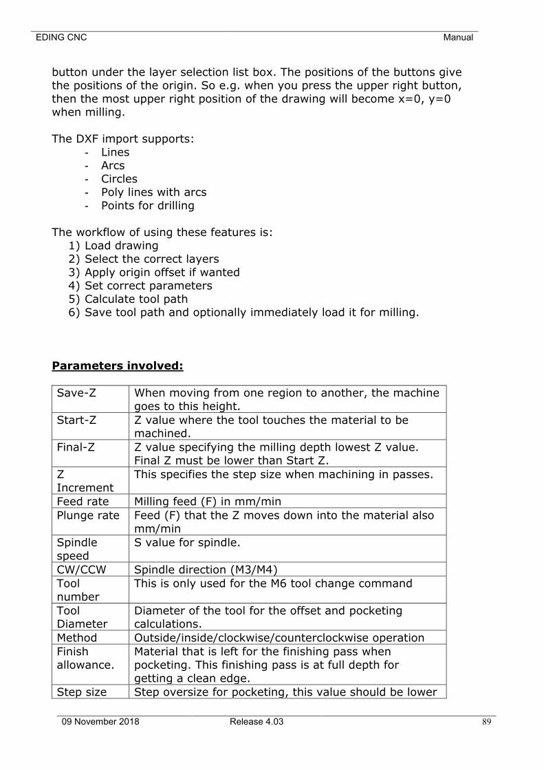
EDING CNC Manual
09 November 2018 Release 4.03 89
button under the layer selection list box. The positions of the buttons give the positions of the origin. So e.g. when you press the upper right button,
then the most upper right position of the drawing will become x=0, y=0 when milling.
The DXF import supports:
- Lines - Arcs
- Circles - Poly lines with arcs
- Points for drilling
The workflow of using these features is: 1) Load drawing
2) Select the correct layers
3) Apply origin offset if wanted 4) Set correct parameters
5) Calculate tool path 6) Save tool path and optionally immediately load it for milling.
Parameters involved:
Save-Z When moving from one region to another, the machine
goes to this height.
Start-Z Z value where the tool touches the material to be machined.
Final-Z Z value specifying the milling depth lowest Z value. Final Z must be lower than Start Z.
Z
Increment
This specifies the step size when machining in passes.
Feed rate Milling feed (F) in mm/min
Plunge rate Feed (F) that the Z moves down into the material also
mm/min
Spindle
speed
S value for spindle.
CW/CCW Spindle direction (M3/M4)
Tool
number
This is only used for the M6 tool change command
Tool Diameter
Diameter of the tool for the offset and pocketing calculations.
Method Outside/inside/clockwise/counterclockwise operation
Finish
allowance.
Material that is left for the finishing pass when
pocketing. This finishing pass is at full depth for
getting a clean edge.
Step size Step oversize for pocketing, this value should be lower
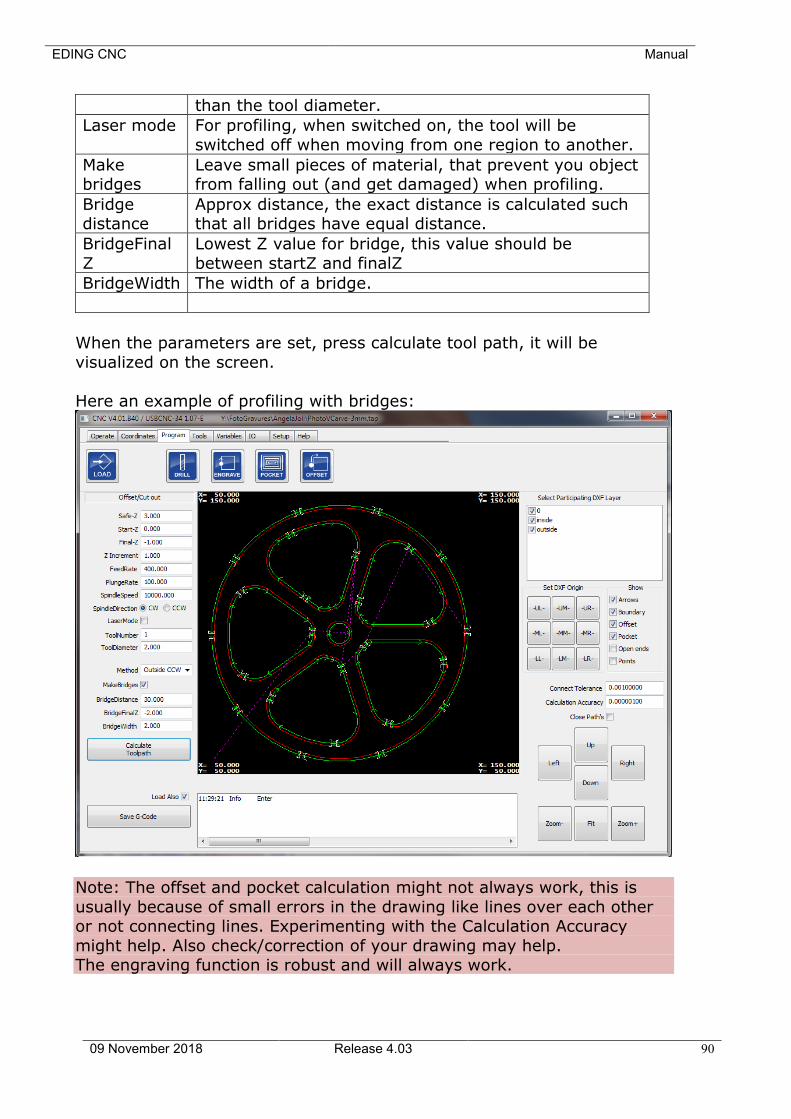
EDING CNC Manual
09 November 2018 Release 4.03 90
than the tool diameter.
Laser mode For profiling, when switched on, the tool will be
switched off when moving from one region to another.
Make bridges
Leave small pieces of material, that prevent you object from falling out (and get damaged) when profiling.
Bridge distance
Approx distance, the exact distance is calculated such that all bridges have equal distance.
BridgeFinal
Z
Lowest Z value for bridge, this value should be
between startZ and finalZ
BridgeWidth The width of a bridge.
When the parameters are set, press calculate tool path, it will be
visualized on the screen.
Here an example of profiling with bridges:
Note: The offset and pocket calculation might not always work, this is
usually because of small errors in the drawing like lines over each other or not connecting lines. Experimenting with the Calculation Accuracy
might help. Also check/correction of your drawing may help. The engraving function is robust and will always work.
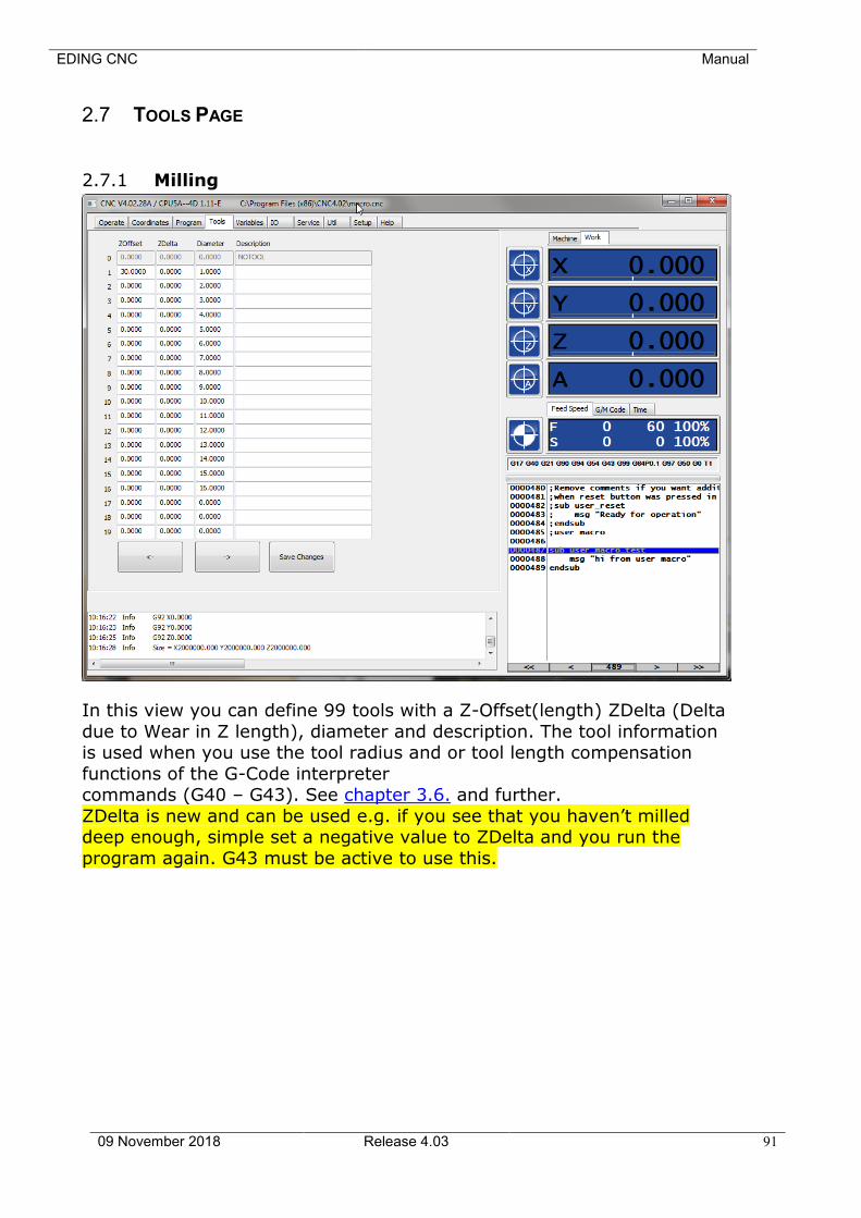
EDING CNC Manual
09 November 2018 Release 4.03 91
2.7 TOOLS PAGE
2.7.1 Milling
In this view you can define 99 tools with a Z-Offset(length) ZDelta (Delta
due to Wear in Z length), diameter and description. The tool information is used when you use the tool radius and or tool length compensation
functions of the G-Code interpreter commands (G40 – G43). See chapter 3.6. and further.
ZDelta is new and can be used e.g. if you see that you haven’t milled deep enough, simple set a negative value to ZDelta and you run the
program again. G43 must be active to use this.
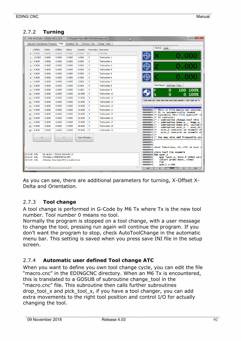
EDING CNC Manual
09 November 2018 Release 4.03 92
2.7.2 Turning
As you can see, there are additional parameters for turning, X-Offset X-Delta and Orientation.
2.7.3 Tool change
A tool change is performed in G-Code by M6 Tx where Tx is the new tool
number. Tool number 0 means no tool. Normally the program is stopped on a tool change, with a user message
to change the tool, pressing run again will continue the program. If you
don’t want the program to stop, check AutoToolChange in the automatic menu bar. This setting is saved when you press save INI file in the setup
screen.
2.7.4 Automatic user defined Tool change ATC
When you want to define you own tool change cycle, you can edit the file “macro.cnc” in the EDINGCNC directory. When an M6 Tx is encountered,
this is translated to a GOSUB of subroutine change_tool in the
“macro.cnc” file. This subroutine then calls further subroutines drop_tool_x and pick_tool_x, if you have a tool changer, you can add
extra movements to the right tool position and control I/O for actually changing the tool.
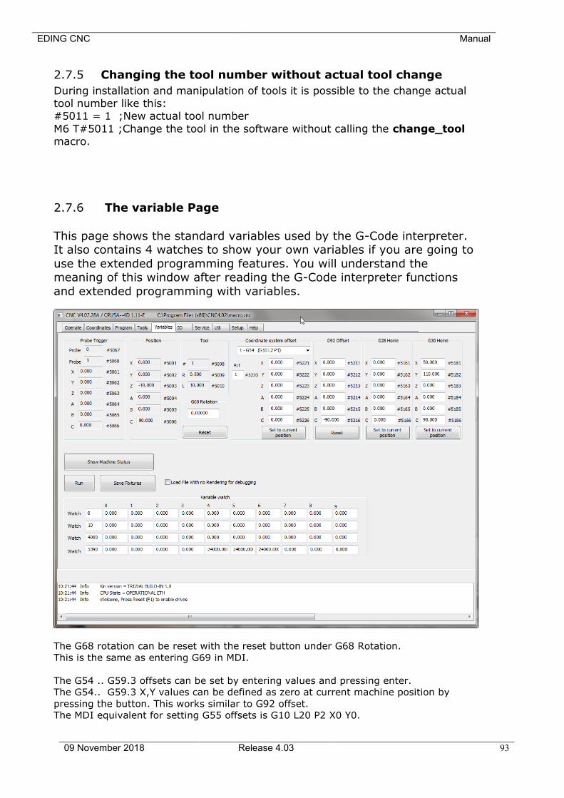
EDING CNC Manual
09 November 2018 Release 4.03 93
2.7.5 Changing the tool number without actual tool change
During installation and manipulation of tools it is possible to the change actual tool number like this: #5011 = 1 ;New actual tool number
M6 T#5011 ;Change the tool in the software without calling the change_tool macro.
2.7.6 The variable Page
This page shows the standard variables used by the G-Code interpreter. It also contains 4 watches to show your own variables if you are going to
use the extended programming features. You will understand the meaning of this window after reading the G-Code interpreter functions
and extended programming with variables.
The G68 rotation can be reset with the reset button under G68 Rotation.
This is the same as entering G69 in MDI.
The G54 .. G59.3 offsets can be set by entering values and pressing enter.
The G54.. G59.3 X,Y values can be defined as zero at current machine position by
pressing the button. This works similar to G92 offset.
The MDI equivalent for setting G55 offsets is G10 L20 P2 X0 Y0.

EDING CNC Manual
09 November 2018 Release 4.03 94
G92 is normally used for zeroing the machine at work piece coordinates. you can reset
all offsets here to zero. The G28 and G30 positions can be defined at current location by
pressing the associated button.

EDING CNC Manual
09 November 2018 Release 4.03 95
2.8 IO PAGE
At this page you can monitor and set the I/O signals for CPU and IO extension board if
attached. You can see that the GPIO extension board signals can be given a more
meaningful name to your application. Note that this page shows the RAW IO values for
the digital IO and does not take inversion into account.
The internal GPIO (AUX) can be controlled by M54, M55, M56, e.g. M54 P1 switches
output AUX1 on and M55 P1 switches output AUX1 off.
The external GPIO can be controlled also by M54, M55, M56, e.g. M54 P101 switches
output 1 of card 1 on.
These M-Codes are further explained in the M Codes chapter of this document.
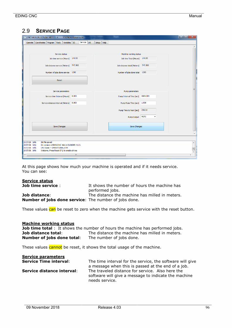
EDING CNC Manual
09 November 2018 Release 4.03 96
2.9 SERVICE PAGE
At this page shows how much your machine is operated and if it needs service.
You can see:
Service status
Job time service : It shows the number of hours the machine has
performed jobs.
Job distance: The distance the machine has milled in meters.
Number of jobs done service: The number of jobs done.
These values can be reset to zero when the machine gets service with the reset button.
Machine working status
Job time total : It shows the number of hours the machine has performed jobs.
Job distance total: The distance the machine has milled in meters.
Number of jobs done total: The number of jobs done.
These values cannot be reset, it shows the total usage of the machine.
Service parameters
Service Time interval: The time interval for the service, the software will give
a message when this is passed at the end of a job.
Service distance interval: The traveled distance for service. Also here the
software will give a message to indicate the machine
needs service.

EDING CNC Manual
09 November 2018 Release 4.03 97
Pump parameters (For Automatic machine oiling system)
Pump Interval Time : Time in seconds between pump actions.
Pump pulse Time: Duration of one pump action.
PumpTimeToNext: Time to next pump action, read only.
Pump Output: Output used for PUMP, set to NONE for no pump
action.
Save changes: Wil set the Pump Time To Next to 5 seconds once for
testing. After that every Pump Interval Time.
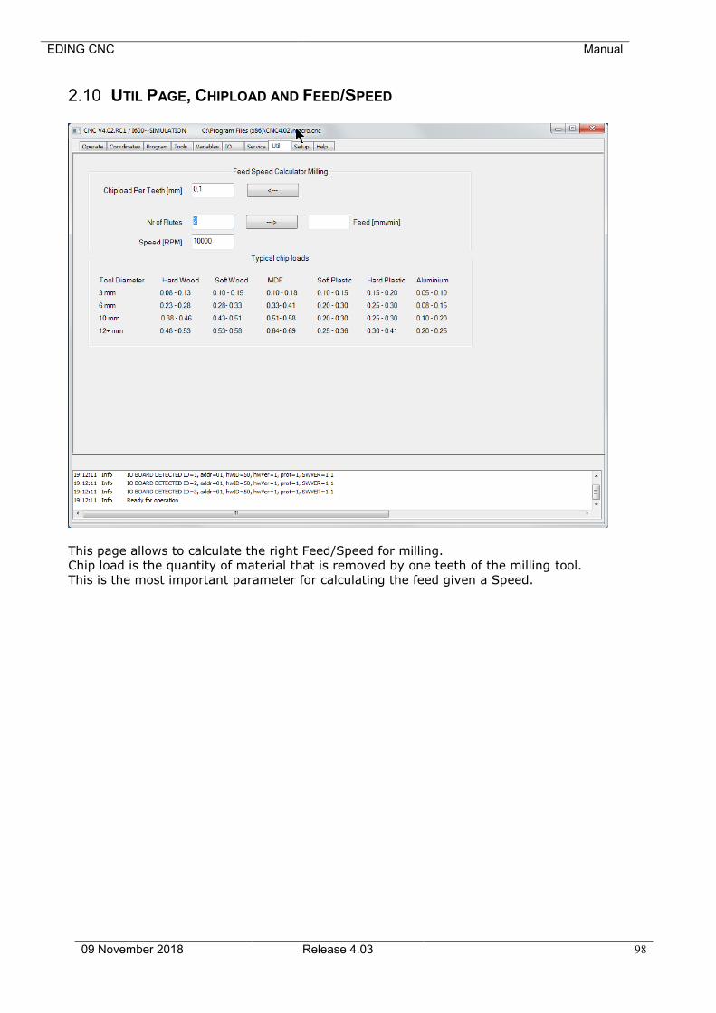
EDING CNC Manual
09 November 2018 Release 4.03 98
2.10 UTIL PAGE, CHIPLOAD AND FEED/SPEED
This page allows to calculate the right Feed/Speed for milling.
Chip load is the quantity of material that is removed by one teeth of the milling tool.
This is the most important parameter for calculating the feed given a Speed.
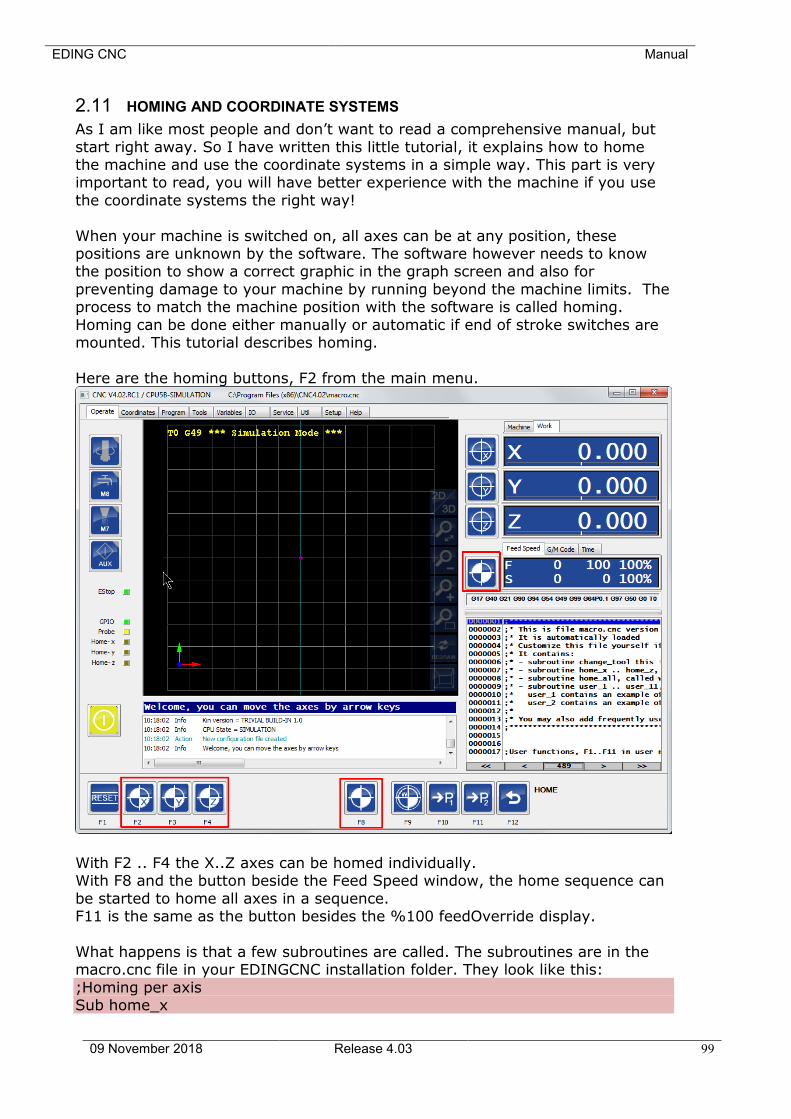
EDING CNC Manual
09 November 2018 Release 4.03 99
2.11 HOMING AND COORDINATE SYSTEMS
As I am like most people and don’t want to read a comprehensive manual, but
start right away. So I have written this little tutorial, it explains how to home the machine and use the coordinate systems in a simple way. This part is very important to read, you will have better experience with the machine if you use
the coordinate systems the right way!
When your machine is switched on, all axes can be at any position, these positions are unknown by the software. The software however needs to know the position to show a correct graphic in the graph screen and also for
preventing damage to your machine by running beyond the machine limits. The process to match the machine position with the software is called homing.
Homing can be done either manually or automatic if end of stroke switches are mounted. This tutorial describes homing.
Here are the homing buttons, F2 from the main menu.
With F2 .. F4 the X..Z axes can be homed individually. With F8 and the button beside the Feed Speed window, the home sequence can
be started to home all axes in a sequence. F11 is the same as the button besides the %100 feedOverride display.
What happens is that a few subroutines are called. The subroutines are in the macro.cnc file in your EDINGCNC installation folder. They look like this:
;Homing per axis Sub home_x
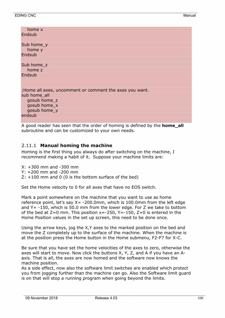
EDING CNC Manual
09 November 2018 Release 4.03 100
home x Endsub
Sub home_y
home y Endsub
Sub home_z home z
Endsub
;Home all axes, uncomment or comment the axes you want. sub home_all
gosub home_z gosub home_x gosub home_y
endsub
A good reader has seen that the order of homing is defined by the home_all subroutine and can be customized to your own needs.
2.11.1 Manual homing the machine
Homing is the first thing you always do after switching on the machine, I
recommend making a habit of it. Suppose your machine limits are:
X: +300 mm and -300 mm Y: +200 mm and -200 mm Z: +100 mm and 0 (0 is the bottom surface of the bed)
Set the Home velocity to 0 for all axes that have no EOS switch.
Mark a point somewhere on the machine that you want to use as home
reference point, let’s say X= -200.0mm, which is 100.0mm from the left edge and Y= -150, which is 50.0 mm from the lower edge. For Z we take to bottom of the bed at Z=0 mm. This position x=-250, Y=-150, Z=0 is entered in the
Home Position values in the set up screen, this need to be done once.
Using the arrow keys, jog the X,Y axes to the marked position on the bed and move the Z completely up to the surface of the machine. When the machine is at the position press the Home button in the Home submenu, F2-F7 for X-C.
Be sure that you have set the home velocities of the axes to zero, otherwise the
axes will start to move. Now click the buttons X, Y, Z, and A if you have an A-axis. That is all, the axes are now homed and the software now knows the machine position.
As a side effect, now also the software limit switches are enabled which protect you from jogging further than the machine can go. Also the Software limit guard
is on that will stop a running program when going beyond the limits.
EDING CNC Manual
09 November 2018 Release 4.03 101
You may also have noticed that the position mode is set to “machine”, this is because homing directly affects the machine coordinate system. From this point
the machine coordinate system, is not changed any more, it stays as is.
HINT: Move your machine always back to the home position if you are done with the machine. You don’t have to move manually to this point next time when you switch back on the machine. You can do a fast move in machine
coordinates like this: g53 g0 x0 y0 z0, or first undo the preset (preset dialog, undo preset) and then do a regular G0.
Another possibility to move quickly to the home positions is using g28, In the variable window set G28 home positions to the same value as the home positions in the set up window. Now you have to type only g28 to go to the
home position.
2.11.2 Automatic homing the machine and HomeIsEstop
The machine needs a homing sensor or switch for each axis connected the its home input on the CPU board.
The homing switch is placed at a small distance of the mechanical end of the machine. This distance is needed to ramp down the velocity after the switch is
activated. The sensor should be mounted such that it remains active until the mechanical limit of the machine.
For automatic homing the home velocity needs to be set to another value than
zero, use an equal or lower speed than the axis maximum speed. The axis should start to move in the direction where your homing switch is mounted, when it is needed to reverse the direction add a minus sign to the homing
velocity. Setup the HomeInputSenseLevel correctly. When the home input led’s on the IO screen are grey when the input is not activated put a 1 here,
when the led’s are yellow when the switch is not activated, put a 0. This depends whether you have used normally open or normally closed switch. I
recommend normally closed switches here. Use the homing sub menu to home your axes.
1st Move: The machine first moves until the switch activates, then ramps down and stops.
2nd Move: Then the direction reverses and ramps down when the switch releases. At the moment of the release of the switch, the position is captured and used to
set your machine position correctly.
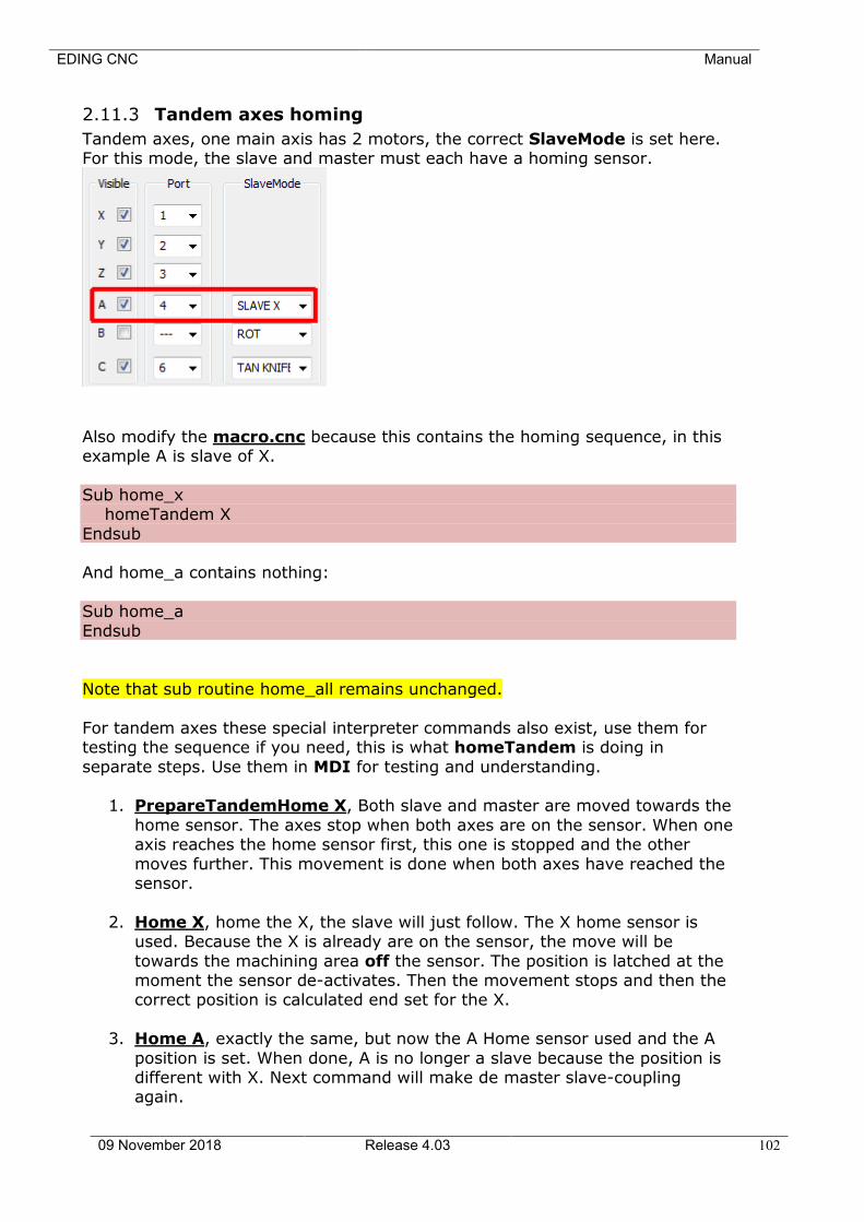
EDING CNC Manual
09 November 2018 Release 4.03 102
2.11.3 Tandem axes homing
Tandem axes, one main axis has 2 motors, the correct SlaveMode is set here. For this mode, the slave and master must each have a homing sensor.
Also modify the macro.cnc because this contains the homing sequence, in this example A is slave of X.
Sub home_x homeTandem X
Endsub And home_a contains nothing:
Sub home_a
Endsub
Note that sub routine home_all remains unchanged.
For tandem axes these special interpreter commands also exist, use them for testing the sequence if you need, this is what homeTandem is doing in
separate steps. Use them in MDI for testing and understanding.
1. PrepareTandemHome X, Both slave and master are moved towards the
home sensor. The axes stop when both axes are on the sensor. When one axis reaches the home sensor first, this one is stopped and the other
moves further. This movement is done when both axes have reached the sensor.
2. Home X, home the X, the slave will just follow. The X home sensor is used. Because the X is already are on the sensor, the move will be
towards the machining area off the sensor. The position is latched at the moment the sensor de-activates. Then the movement stops and then the correct position is calculated end set for the X.
3. Home A, exactly the same, but now the A Home sensor used and the A
position is set. When done, A is no longer a slave because the position is different with X. Next command will make de master slave-coupling again.
EDING CNC Manual
09 November 2018 Release 4.03 103
4. At this point both master and slave have a correct known position but
probably different. It can be equalized by moving the slave axis to the position of the A axis. This is done by command MoveSlaveToMaster A.
The slave will move to the same position as the master. The bridge is set straight and we are done. (If the bridge is not straight, adjust the home positions in the setup).

EDING CNC Manual
09 November 2018 Release 4.03 104
2.11.4 Work versus Machine coordinate system and zeroing
The machine coordinate system does not change, however we want to be able to do the milling of our part anywhere we want on the machine. We will normally use the “work” coordinate system, we can shift it anywhere we want.
This can be done with several G-Codes, which are explained in chapter 3, it can also be done using the “preset” button on the operator screen, we’ll see this in a
minute. Suppose our g-code file containing the work piece is created with an origin of
X=0, Y=0, Z=0. This is because you have drawn your part in a CAD program beginning from these coordinates and then converted to G-Code.
Now you have put your raw material somewhere on the machine, probably not at coordinates X=0, Y=0, Z=0. By the way, I prefer to define the upper surface of the material as Z=0, such
that a negative Z value goes into the material.
Just move to the zero point of the work piece and there press the zero buttons in the operate screen besides the position display.
For the advanced users: The zeroing can also be done using a measuring probe connected to the probe input. An example is provided in the standard macro.cnc
file. Under user_1 you find automatic zeroing. Under user_2 you find interactive tool length measurement.
If you want to do it a more advanced way, look at G55 .. G59.3 and also at the G92 variants.
When homing and zeroing is performed, the milling can start:
When the program is loaded, go to the graphics screen (Alt-g) and press update preview, you will now see exactly where the part is going to be milled at the
surface of you machine bed.
Now press the F4 key or the run button to start milling, go to the graphic screen and switch real time graph on to see what the machine is doing.
That’s all for this tutorial, happy milling!
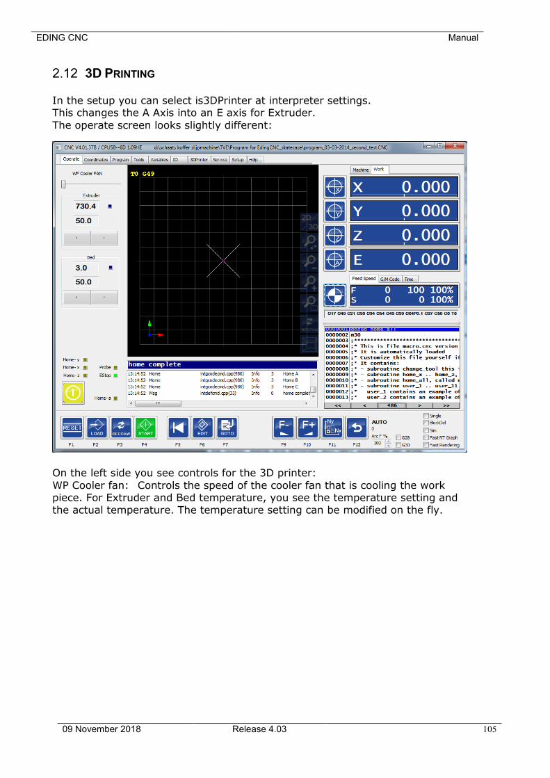
EDING CNC Manual
09 November 2018 Release 4.03 105
2.12 3D PRINTING
In the setup you can select is3DPrinter at interpreter settings. This changes the A Axis into an E axis for Extruder.
The operate screen looks slightly different:
On the left side you see controls for the 3D printer:
WP Cooler fan: Controls the speed of the cooler fan that is cooling the work piece. For Extruder and Bed temperature, you see the temperature setting and the actual temperature. The temperature setting can be modified on the fly.
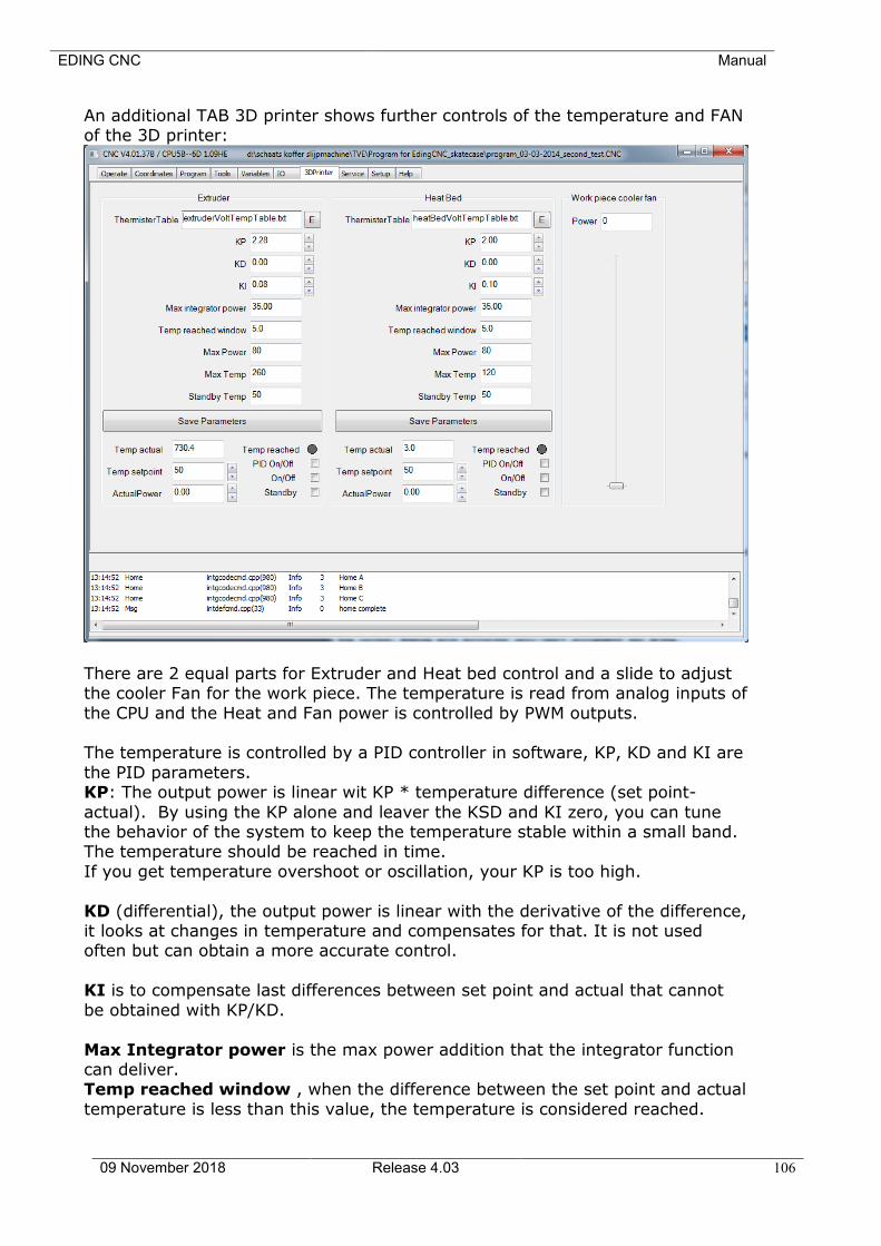
EDING CNC Manual
09 November 2018 Release 4.03 106
An additional TAB 3D printer shows further controls of the temperature and FAN of the 3D printer:
There are 2 equal parts for Extruder and Heat bed control and a slide to adjust the cooler Fan for the work piece. The temperature is read from analog inputs of
the CPU and the Heat and Fan power is controlled by PWM outputs. The temperature is controlled by a PID controller in software, KP, KD and KI are
the PID parameters. KP: The output power is linear wit KP * temperature difference (set point-
actual). By using the KP alone and leaver the KSD and KI zero, you can tune the behavior of the system to keep the temperature stable within a small band. The temperature should be reached in time.
If you get temperature overshoot or oscillation, your KP is too high.
KD (differential), the output power is linear with the derivative of the difference, it looks at changes in temperature and compensates for that. It is not used often but can obtain a more accurate control.
KI is to compensate last differences between set point and actual that cannot
be obtained with KP/KD.
Max Integrator power is the max power addition that the integrator function can deliver. Temp reached window , when the difference between the set point and actual
temperature is less than this value, the temperature is considered reached.
EDING CNC Manual
09 November 2018 Release 4.03 107
Max power is the total maximum power that the system. will give to its PWM output.
Max temp is a safety value when this temperature is reached the power is
switched off. Standby temp, is activate when the system is put in standby mode.
Temp Reached turns green when reached.
PID on/off switch the PID control system OFF. On/Off when checked you can directly control (to test) the actual power from 1-100%.
Standby activates the standby temperature.
M1 :All heating and Fans off M104 S :Set extruder temperature, (M104 S50, sets temperature to 50
degree Celsius). M106 S.. : Work piece cooling FAN ON optionally with S=0-255, for 0-100%
PWM M107 :Work piece FAN off .
M109 S.. :Set extruder temperature and wait until reached. M143 S.. :Maximum Hot-end temperature to prevent overheating. M140 S.. :Bed temperature
M143 S.. :Set max extruder temperature M190 S.. :Set Bed temperature and wait until reached.
All other un-useful or unimplemented special M functions are ignored.
A logging file for the temperature and power can be generated using interpreter command: TempLog <on|off>
The file can be graphically shown by gnuplot. This script shows the extruder temperature and power, you can put it into a file
like “plot_temperature.plt” and open it with gnuplot: set key autotitle columnhead
set ytics nomirror
set y2tics
set xlabel 'time'
set ylabel 'temp'
set y2label 'power'
#plot extruder act and set temperature and power
plot 'templog.dat' u 1:2 w l, "" u 1:3 w l, "" u 1:4 w l axes x1y2
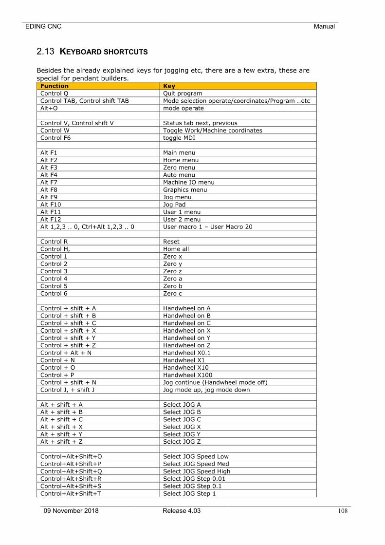
EDING CNC Manual
09 November 2018 Release 4.03 108
2.13 KEYBOARD SHORTCUTS
Besides the already explained keys for jogging etc, there are a few extra, these are
special for pendant builders. Function Key
Control Q Quit program
Control TAB, Control shift TAB Mode selection operate/coordinates/Program ..etc
Alt+O mode operate
Control V, Control shift V Status tab next, previous
Control W Toggle Work/Machine coordinates
Control F6 toggle MDI
Alt F1 Main menu
Alt F2 Home menu
Alt F3 Zero menu
Alt F4 Auto menu
Alt F7 Machine IO menu
Alt F8 Graphics menu
Alt F9 Jog menu
Alt F10 Jog Pad
Alt F11 User 1 menu
Alt F12 User 2 menu
Alt 1,2,3 .. 0, Ctrl+Alt 1,2,3 .. 0 User macro 1 – User Macro 20
Control R Reset
Control H, Home all
Control 1 Zero x
Control 2 Zero y
Control 3 Zero z
Control 4 Zero a
Control 5 Zero b
Control 6 Zero c
Control + shift + A Handwheel on A
Control + shift + B Handwheel on B
Control + shift + C Handwheel on C
Control + shift + X Handwheel on X
Control + shift + Y Handwheel on Y
Control + shift + Z Handwheel on Z
Control + Alt + N Handwheel X0.1
Control + N Handwheel X1
Control + O Handwheel X10
Control + P Handwheel X100
Control + shift + N Jog continue (Handwheel mode off)
Control J, + shift J Jog mode up, jog mode down
Alt + shift + A Select JOG A
Alt + shift + B Select JOG B
Alt + shift + C Select JOG C
Alt + shift + X Select JOG X
Alt + shift + Y Select JOG Y
Alt + shift + Z Select JOG Z
Control+Alt+Shift+O Select JOG Speed Low
Control+Alt+Shift+P Select JOG Speed Med
Control+Alt+Shift+Q Select JOG Speed High
Control+Alt+Shift+R Select JOG Step 0.01
Control+Alt+Shift+S Select JOG Step 0.1
Control+Alt+Shift+T Select JOG Step 1
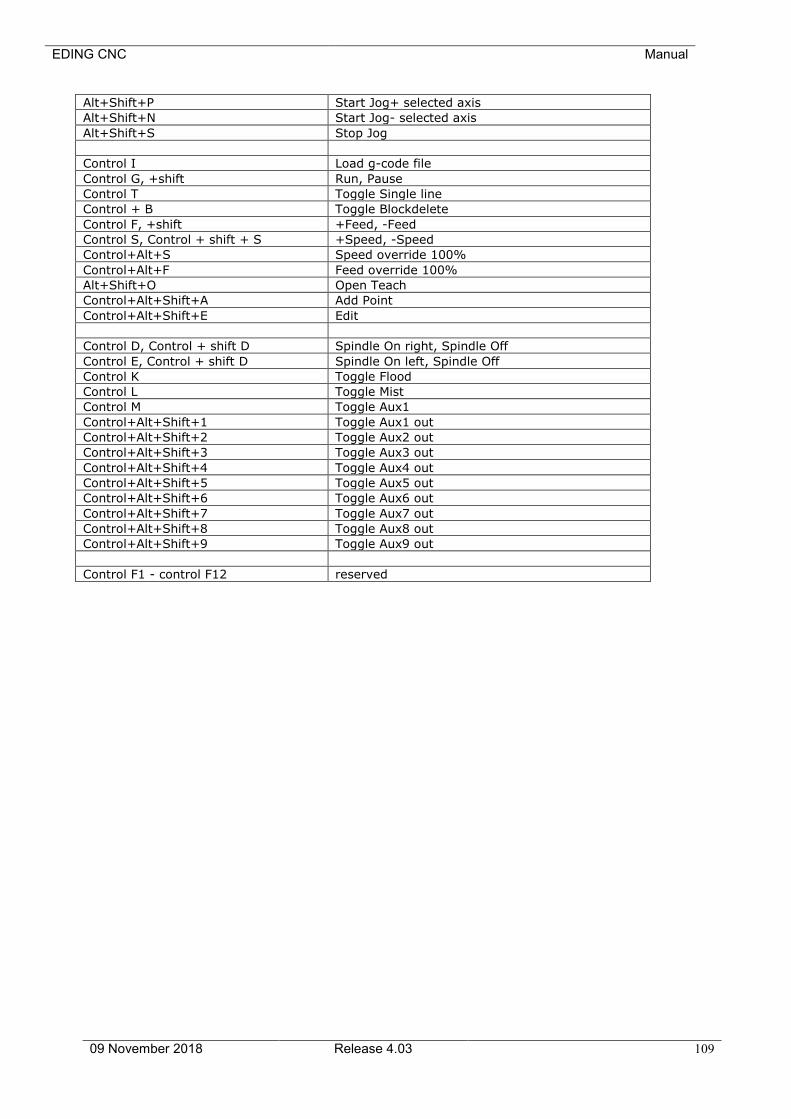
EDING CNC Manual
09 November 2018 Release 4.03 109
Alt+Shift+P Start Jog+ selected axis
Alt+Shift+N Start Jog- selected axis
Alt+Shift+S Stop Jog
Control I Load g-code file
Control G, +shift Run, Pause
Control T Toggle Single line
Control + B Toggle Blockdelete
Control F, +shift +Feed, -Feed
Control S, Control + shift + S +Speed, -Speed
Control+Alt+S Speed override 100%
Control+Alt+F Feed override 100%
Alt+Shift+O Open Teach
Control+Alt+Shift+A Add Point
Control+Alt+Shift+E Edit
Control D, Control + shift D Spindle On right, Spindle Off
Control E, Control + shift D Spindle On left, Spindle Off
Control K Toggle Flood
Control L Toggle Mist
Control M Toggle Aux1
Control+Alt+Shift+1 Toggle Aux1 out
Control+Alt+Shift+2 Toggle Aux2 out
Control+Alt+Shift+3 Toggle Aux3 out
Control+Alt+Shift+4 Toggle Aux4 out
Control+Alt+Shift+5 Toggle Aux5 out
Control+Alt+Shift+6 Toggle Aux6 out
Control+Alt+Shift+7 Toggle Aux7 out
Control+Alt+Shift+8 Toggle Aux8 out
Control+Alt+Shift+9 Toggle Aux9 out
Control F1 - control F12 reserved
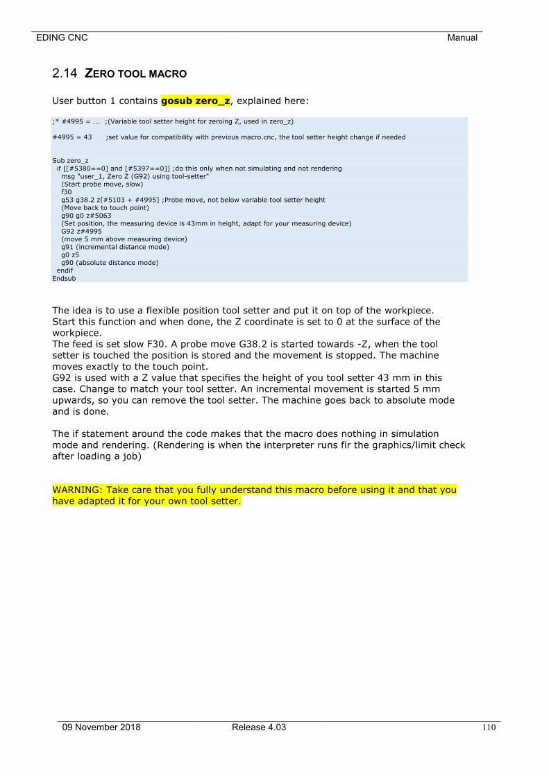
EDING CNC Manual
09 November 2018 Release 4.03 110
2.14 ZERO TOOL MACRO
User button 1 contains gosub zero_z, explained here:
;* #4995 = ... ;(Variable tool setter height for zeroing Z, used in zero_z)
#4995 = 43 ;set value for compatibility with previous macro.cnc, the tool setter height change if needed
Sub zero_z
if [[#5380==0] and [#5397==0]] ;do this only when not simulating and not rendering
msg "user_1, Zero Z (G92) using tool-setter"
(Start probe move, slow)
f30
g53 g38.2 z[#5103 + #4995] ;Probe move, not below variable tool setter height
(Move back to touch point)
g90 g0 z#5063
(Set position, the measuring device is 43mm in height, adapt for your measuring device) G92 z#4995
(move 5 mm above measuring device)
g91 (incremental distance mode)
g0 z5
g90 (absolute distance mode)
endif
Endsub
The idea is to use a flexible position tool setter and put it on top of the workpiece.
Start this function and when done, the Z coordinate is set to 0 at the surface of the
workpiece.
The feed is set slow F30. A probe move G38.2 is started towards -Z, when the tool
setter is touched the position is stored and the movement is stopped. The machine
moves exactly to the touch point.
G92 is used with a Z value that specifies the height of you tool setter 43 mm in this
case. Change to match your tool setter. An incremental movement is started 5 mm
upwards, so you can remove the tool setter. The machine goes back to absolute mode
and is done.
The if statement around the code makes that the macro does nothing in simulation
mode and rendering. (Rendering is when the interpreter runs fir the graphics/limit check
after loading a job)
WARNING: Take care that you fully understand this macro before using it and that you
have adapted it for your own tool setter.
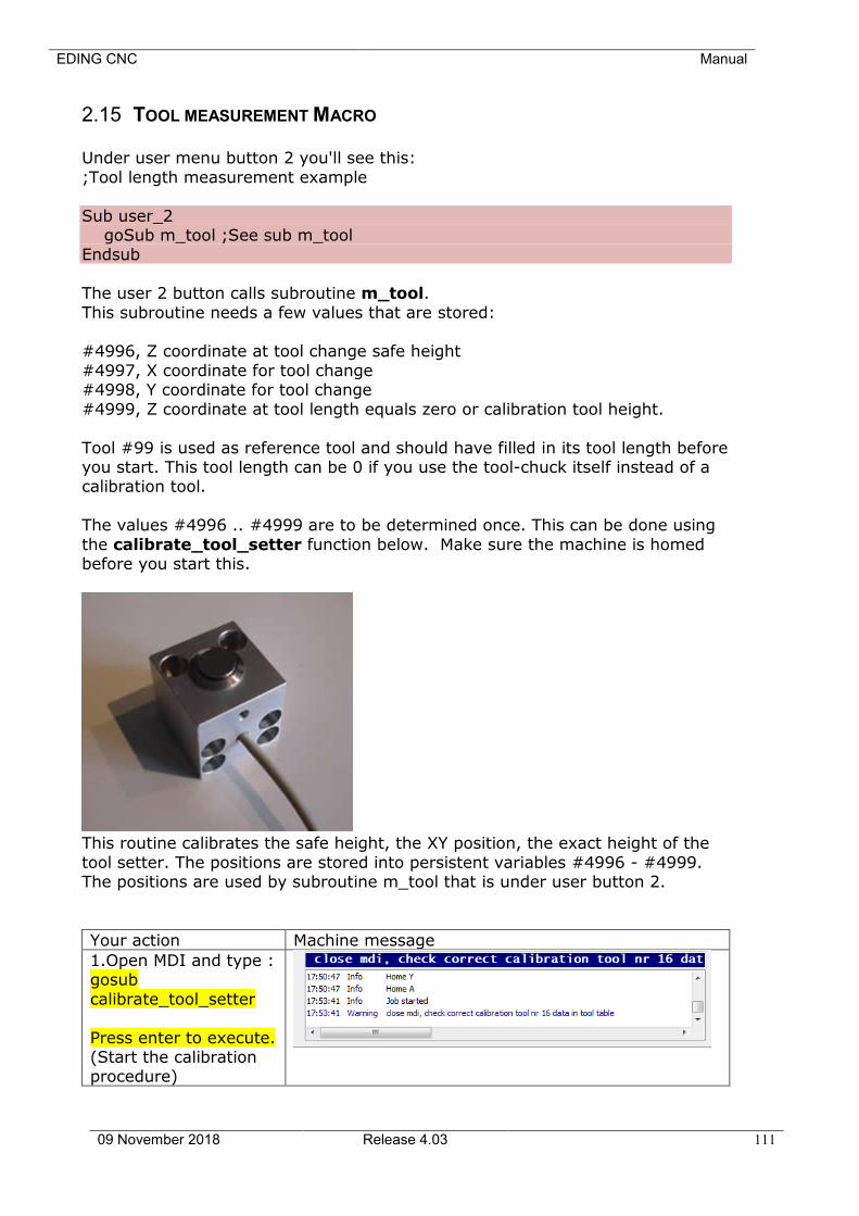
EDING CNC Manual
09 November 2018 Release 4.03 111
2.15 TOOL MEASUREMENT MACRO
Under user menu button 2 you'll see this:
;Tool length measurement example
Sub user_2 goSub m_tool ;See sub m_tool Endsub
The user 2 button calls subroutine m_tool.
This subroutine needs a few values that are stored: #4996, Z coordinate at tool change safe height
#4997, X coordinate for tool change #4998, Y coordinate for tool change
#4999, Z coordinate at tool length equals zero or calibration tool height.
Tool #99 is used as reference tool and should have filled in its tool length before you start. This tool length can be 0 if you use the tool-chuck itself instead of a calibration tool.
The values #4996 .. #4999 are to be determined once. This can be done using
the calibrate_tool_setter function below. Make sure the machine is homed before you start this.
This routine calibrates the safe height, the XY position, the exact height of the
tool setter. The positions are stored into persistent variables #4996 - #4999. The positions are used by subroutine m_tool that is under user button 2.
Your action Machine message
1.Open MDI and type : gosub
calibrate_tool_setter
Press enter to execute. (Start the calibration procedure)

EDING CNC Manual
09 November 2018 Release 4.03 112
2.Close the MDI
window using F6, Go to the tools tab and check the tool length
of tool 99. For me it is 0 because I use the
tool chuck without calibration tool.
Press save changes. and go back to the
operate tab. (tool 99 is used as
calibration tool, set length correctly,
normally this would be zero, or if the calibration tool has a
defined length, set that length)
3.The program is still inside subroutine
calibrate_tool_setter. Press RUN to continue.
(Calibration length is set correctly in tool
table)
4.Do what the
message says: Jog Z to safe height. In my case this is
completely up. Press RUN to continue
(This calibrates the
safe height)
5.Do what the messages says:
Insert the calibration tool if you have one, or
just leave the tool chuck empty.
Jog using X, Y, Z just above the tool setter.
When done jogging, press RUN.
The machine will move down to touch the tool setter, The measured tool-chuck height is stored into #4999.
Then the Z is moved up to safe height.
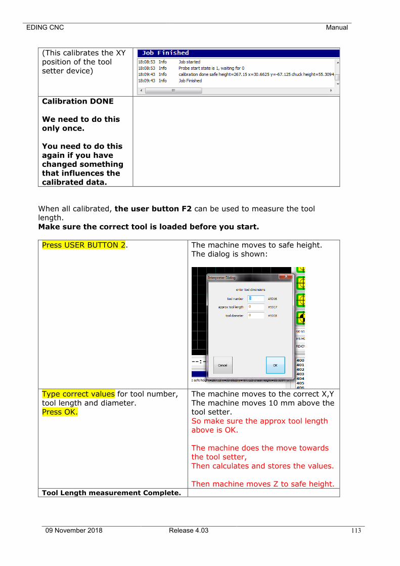
EDING CNC Manual
09 November 2018 Release 4.03 113
(This calibrates the XY
position of the tool setter device)
Calibration DONE
We need to do this only once.
You need to do this
again if you have changed something that influences the
calibrated data.
When all calibrated, the user button F2 can be used to measure the tool length.
Make sure the correct tool is loaded before you start.
Press USER BUTTON 2. The machine moves to safe height. The dialog is shown:
Type correct values for tool number,
tool length and diameter. Press OK.
The machine moves to the correct X,Y
The machine moves 10 mm above the tool setter.
So make sure the approx tool length above is OK.
The machine does the move towards the tool setter,
Then calculates and stores the values.
Then machine moves Z to safe height. Tool Length measurement Complete.
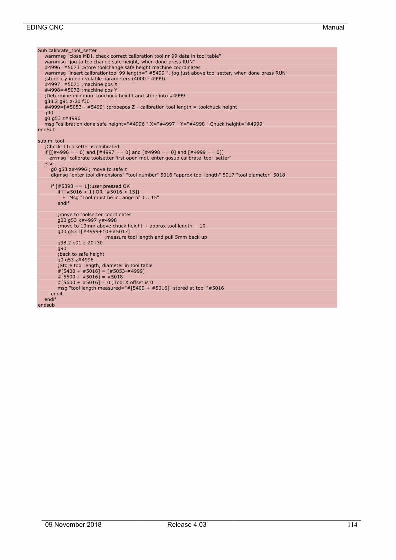
EDING CNC Manual
09 November 2018 Release 4.03 114
Sub calibrate_tool_setter
warnmsg "close MDI, check correct calibration tool nr 99 data in tool table"
warnmsg "jog to toolchange safe height, when done press RUN"
#4996=#5073 ;Store toolchange safe height machine coordinates warnmsg "insert calibrationtool 99 length=" #5499 ", jog just above tool setter, when done press RUN"
;store x y in non volatile parameters (4000 - 4999)
#4997=#5071 ;machine pos X
#4998=#5072 ;machine pos Y
;Determine minimum toochuck height and store into #4999
g38.2 g91 z-20 f30
#4999=[#5053 - #5499] ;probepos Z - calibration tool length = toolchuck height
g90
g0 g53 z#4996
msg "calibration done safe height="#4996 " X="#4997 " Y="#4998 " Chuck height="#4999 endSub
sub m_tool
;Check if toolsetter is calibrated
if [[#4996 == 0] and [#4997 == 0] and [#4998 == 0] and [#4999 == 0]]
errmsg "calibrate toolsetter first open mdi, enter gosub calibrate_tool_setter"
else
g0 g53 z#4996 ; move to safe z
dlgmsg "enter tool dimensions" "tool number" 5016 "approx tool length" 5017 "tool diameter" 5018
if [#5398 == 1];user pressed OK
if [[#5016 < 1] OR [#5016 > 15]]
ErrMsg "Tool must be in range of 0 .. 15"
endif
;move to toolsetter coordinates
g00 g53 x#4997 y#4998
;move to 10mm above chuck height + approx tool length + 10
g00 g53 z[#4999+10+#5017] ;measure tool length and pull 5mm back up
g38.2 g91 z-20 f30
g90
;back to safe height
g0 g53 z#4996
;Store tool length, diameter in tool table
#[5400 + #5016] = [#5053-#4999]
#[5500 + #5016] = #5018
#[5600 + #5016] = 0 ;Tool X offset is 0 msg "tool length measured="#[5400 + #5016]" stored at tool "#5016
endif
endif
endsub
EDING CNC Manual
09 November 2018 Release 4.03 115
3 Input: the RS274/NGC Language This chapter describes the input language, RS274/NGC. Overview
The RS274/NGC language is based on lines of code. Each line (also called a "block") may include commands to a machining center to do several different
things. Lines of code may be collected in a file to make a program.
A typical line of code consists of an optional line number at the beginning followed by one or more "words." A word consists of a letter followed by a number (or something that evaluates to a number). A word may either give a
command or provide an argument to a command. For example, "G1 X3" is a valid line of code with two words. "G1" is a command meaning "move in a
straight line at the programmed feed rate," and "X3" provides an argument value (the value of X should be 3 at the end of the move). Most RS274/NGC commands start with either G or M (for miscellaneous). The words for these
commands are called "G codes" and "M codes."
The RS274/NGC language has no indicator for the start of a program. The RS274/NGC language has two commands (M2 or M30), either of which ends a program.

EDING CNC Manual
09 November 2018 Release 4.03 116
3.1 SYSTEM-PARAMETERS/VARIABLES
In the RS274/NGC language view, a machining center maintains an array of
5999 numerical parameters. They can be accessed by #1 .. #5999. The specific parameters with dedicated function are listed in the table below. Other parameters in range of 1..5999 are free to use in your G-Code program.
A simple example of usage:
#50=100 ; assign the value 100 to variable #50
G0[#50] ; use #50 to move to 100
Parameters with specific meaning are listed in this table below.
Parameter number
Meaning
Parameters wit this background color are
read only.
Read only
1-26 Used for parameters when overriding m-
functions.
When in the g-code there is e.g.
M999 X100 S1000
And you have in your macro.cnc:
Sub m999 msg “this is my m999 X=”#24” S=”#19
Endsub
Inside the subroutine, the given X and S parameters are at #24 and #19
#1-#26 = A – Z parameter value.
Values are negative -1e10 if not provided
with m999 in this example.

EDING CNC Manual
09 November 2018 Release 4.03 117
Parameter number
Meaning
27-4999 Free to use, note that 4996 – 4999 are used by the tool length measurement function under user
button 2.
Z#4996 safe height for tool measurement above
the fixed tool setter. x#4997 y#4998 fixed tool setter position.
z#4999 chuck height, or zero length tool height, chuck just touches the fixed tool setter at this
height.
Z#4995 is used for the tool setter height for zeroing Z under user button 1.
4000-4999 Free to use, persistent, see above some of these
are used by tool length measurement and zeroing.
5001-5006 POS X – C, interpreter position = work position
5008 Actual TOOL #
5009 Actual TOOL Radius
5010 Actual TOOL Z offset (Length + zDelta)
5011 New tool during tool change
5012 Actual tool X offset (X offset + xDelta)
5013 Actual G43 Z offset (Z offset + zDelta)
5014 Actual G43 X offset (X offset + xDelta)
5015 - 5050 Used in tool change sub routine
5051 - 5056 Probe position X – C in machine coordinates
5061 - 5066 Probe position X – C in work coordinates
5067 1 if probe is triggered after G38.2, 0 otherwise.
5068 Actual Probe value
5069 Hand-wheel counter.
5070 Spindle rate in rev/second
5071-5076 POS X – C, interpreter position without offsets
= Machine position.
5081-5086 Probe position X – C in joint coordinates
5101-5106 MCA NEG LIMIT X - C
5111-5116 MCA POS LIMIT X - C
5121-5126 HOME X-C
5131-5133 TCA NEG LIMIT X-Z
5141-5143 TCA POS LIMIT X-Z
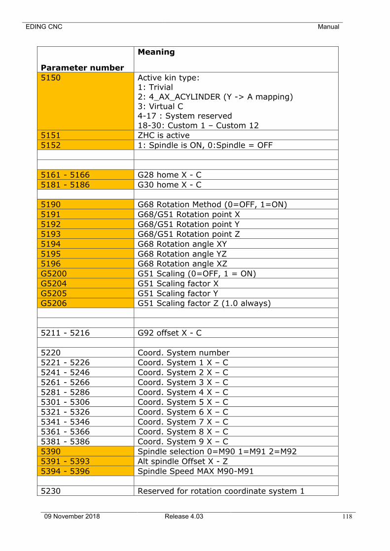
EDING CNC Manual
09 November 2018 Release 4.03 118
Parameter number
Meaning
5150 Active kin type: 1: Trivial
2: 4_AX_ACYLINDER (Y -> A mapping)
3: Virtual C 4-17 : System reserved
18-30: Custom 1 – Custom 12
5151 ZHC is active
5152 1: Spindle is ON, 0:Spindle = OFF
5161 - 5166 G28 home X - C
5181 - 5186 G30 home X - C
5190 G68 Rotation Method (0=OFF, 1=ON)
5191 G68/G51 Rotation point X
5192 G68/G51 Rotation point Y
5193 G68/G51 Rotation point Z
5194 G68 Rotation angle XY
5195 G68 Rotation angle YZ
5196 G68 Rotation angle XZ
G5200 G51 Scaling (0=OFF, 1 = ON)
G5204 G51 Scaling factor X
G5205 G51 Scaling factor Y
G5206 G51 Scaling factor Z (1.0 always)
5211 - 5216 G92 offset X - C
5220 Coord. System number
5221 - 5226 Coord. System 1 X – C
5241 - 5246 Coord. System 2 X – C
5261 - 5266 Coord. System 3 X – C
5281 - 5286 Coord. System 4 X – C
5301 - 5306 Coord. System 5 X – C
5321 - 5326 Coord. System 6 X – C
5341 - 5346 Coord. System 7 X – C
5361 - 5366 Coord. System 8 X – C
5381 - 5386 Coord. System 9 X – C
5390 Spindle selection 0=M90 1=M91 2=M92
5391 - 5393 Alt spindle Offset X - Z
5394 - 5396 Spindle Speed MAX M90-M91
5230 Reserved for rotation coordinate system 1
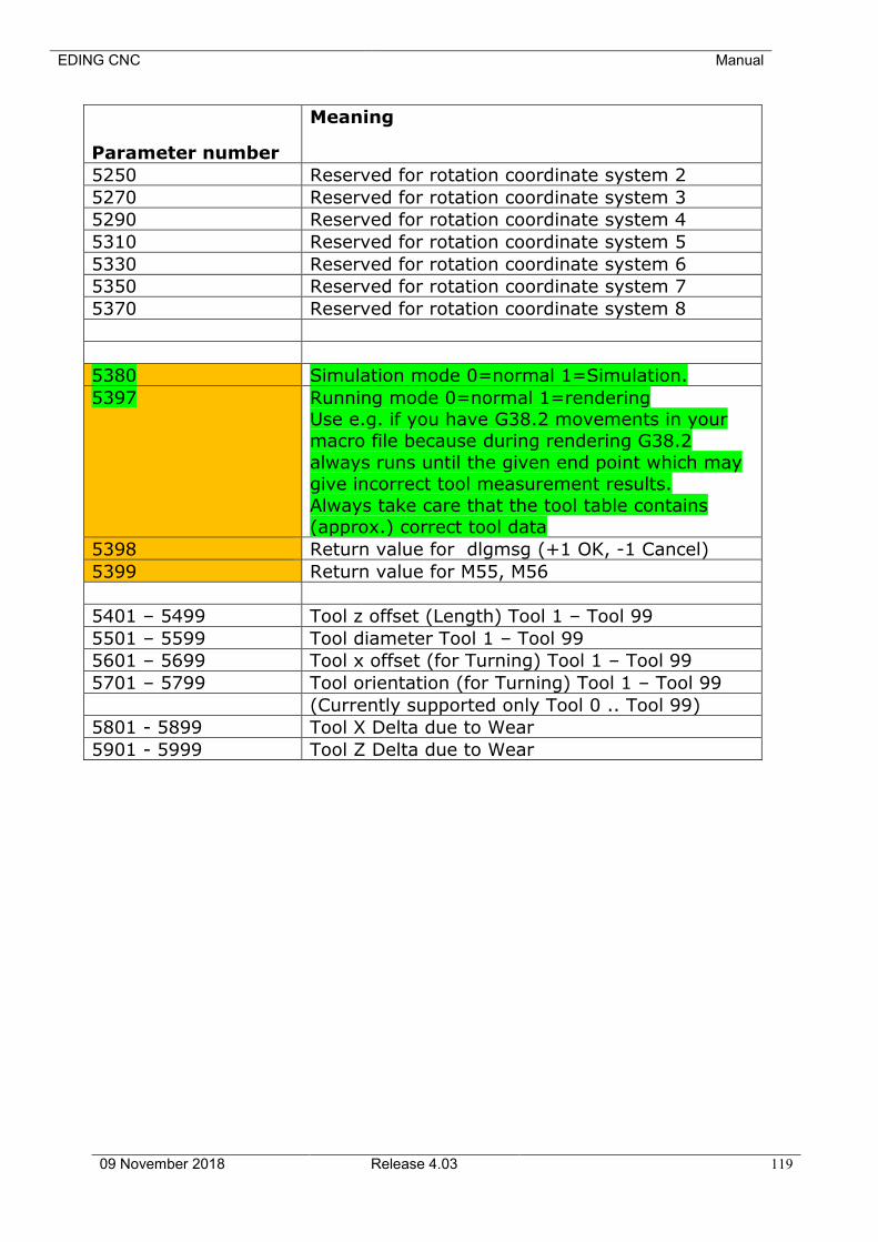
EDING CNC Manual
09 November 2018 Release 4.03 119
Parameter number
Meaning
5250 Reserved for rotation coordinate system 2
5270 Reserved for rotation coordinate system 3
5290 Reserved for rotation coordinate system 4
5310 Reserved for rotation coordinate system 5
5330 Reserved for rotation coordinate system 6
5350 Reserved for rotation coordinate system 7
5370 Reserved for rotation coordinate system 8
5380 Simulation mode 0=normal 1=Simulation.
5397 Running mode 0=normal 1=rendering Use e.g. if you have G38.2 movements in your
macro file because during rendering G38.2
always runs until the given end point which may give incorrect tool measurement results.
Always take care that the tool table contains (approx.) correct tool data
5398 Return value for dlgmsg (+1 OK, -1 Cancel)
5399 Return value for M55, M56
5401 – 5499 Tool z offset (Length) Tool 1 – Tool 99
5501 – 5599 Tool diameter Tool 1 – Tool 99
5601 – 5699 Tool x offset (for Turning) Tool 1 – Tool 99
5701 – 5799 Tool orientation (for Turning) Tool 1 – Tool 99
(Currently supported only Tool 0 .. Tool 99)
5801 - 5899 Tool X Delta due to Wear
5901 - 5999 Tool Z Delta due to Wear
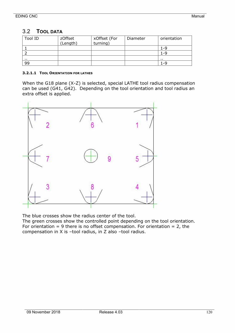
EDING CNC Manual
09 November 2018 Release 4.03 120
3.2 TOOL DATA
Tool ID zOffset
(Length)
xOffset (For
turning)
Diameter orientation
1 1-9
2 1-9
.. ..
99 1-9
3.2.1.1 TOOL ORIENTATION FOR LATHES
When the G18 plane (X-Z) is selected, special LATHE tool radius compensation can be used (G41, G42). Depending on the tool orientation and tool radius an
extra offset is applied.
The blue crosses show the radius center of the tool.
The green crosses show the controlled point depending on the tool orientation. For orientation = 9 there is no offset compensation. For orientation = 2, the compensation in X is –tool radius, in Z also –tool radius.

EDING CNC Manual
09 November 2018 Release 4.03 121
3.3 COORDINATE SYSTEMS
In the RS274/NGC language view, a machining center has an absolute
coordinate system and nine program coordinate systems. You can set the offsets of the nine program coordinate systems using G10 L2 Pn
(n is the number of the coordinate system) with values for the axes in terms of the absolute coordinate system.
You can select one of the nine systems by using G54, G55, G56, G57, G58, G59, G59.1, G59.2, or G59.3 . It is not possible to select the absolute
coordinate system directly.
You can offset the current coordinate system using G92 or G92.3. This offset will then apply to all nine program coordinate systems. This offset may be cancelled with G92.1 or G92.2.
You can make straight moves in the absolute machine coordinate system by using G53 with either G0 or G1.
Data for coordinate systems is stored in parameters, see the previous section.
During initialization, the coordinate system is selected that is specified by
parameter 5220. A value of 1 means the first coordinate system (the one G54 activates), a value of 2 means the second coordinate system (the
one G55 activates), and so on. It is an error for the value of parameter 5220 to be anything but a whole number between one and nine.
The g-code are described in detail in section 3.6

EDING CNC Manual
09 November 2018 Release 4.03 122
3.4 FORMAT OF A LINE
A permissible line of input RS274/NGC code consists of the following, in order,
with the restriction that there is a maximum (currently 256) to the number of characters allowed on a line. • An optional line number.
• Any number of words, parameter settings, and comments.
Any input not explicitly allowed is illegal and will cause the Interpreter to signal an error. Spaces and tabs are allowed anywhere on a line of code and do not change the
meaning of the line, except inside comments. This makes some strange-looking input legal. The line "g0x +0. 12 34y 7" is equivalent to "g0 x+0.1234 y7", for
example. Blank lines are allowed in the input. They are to be ignored.
Input is case insensitive.
3.4.1 Line Number
A line number is the letter N followed by an integer (with no sign) between 0
and 99999 written with no more than five digits (000009 is not OK, for example). Line numbers may be repeated or used out of order, although normal practice is to avoid such usage.
Line numbers may also be skipped, and that is normal practice. A line number is not required to be used, but must be in the proper place if used.
3.4.2 Word
A word is a letter other than N followed by a real value. Words may begin with any of the letters shown in Table 3-2. The table includes N for completeness, even though, as defined above, line numbers are not
words. Several letters (I, J, K, L, P, and R) may have different meanings in different contexts.
Letter Meaning
A A-axis of machine
D Tool radius compensation number
F Feed rate
G General function (see Table 3-4)
H Tool length offset index
I X-axis offset for arcs X offset in G87 canned cycle
J Y-axis offset for arcs Y offset in G87 canned cycle
K Z-axis offset for arcs Z offset in G87 canned cycle
L number of repetitions in canned cycles key used with G10
M miscellaneous function (see Table 3-6)
N line number
P dwell time in canned cycles dwell time with G4 key used with
G10
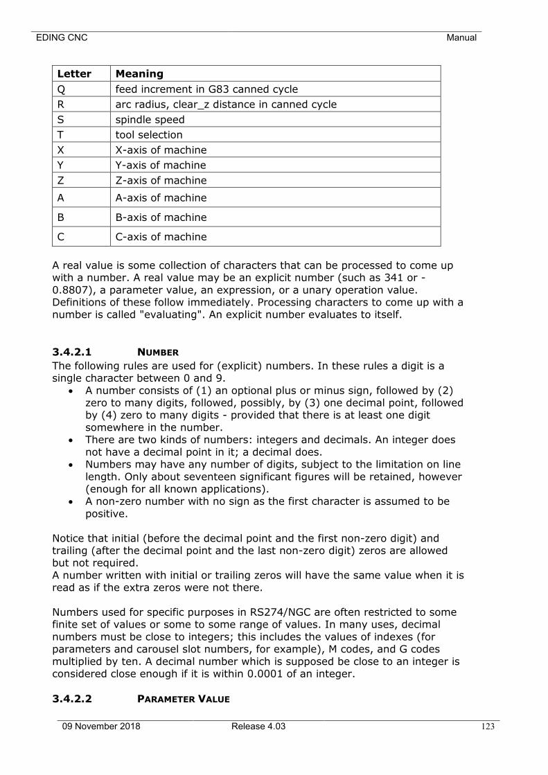
EDING CNC Manual
09 November 2018 Release 4.03 123
Letter Meaning
Q feed increment in G83 canned cycle
R arc radius, clear_z distance in canned cycle
S spindle speed
T tool selection
X X-axis of machine
Y Y-axis of machine
Z Z-axis of machine
A A-axis of machine
B B-axis of machine
C C-axis of machine
A real value is some collection of characters that can be processed to come up with a number. A real value may be an explicit number (such as 341 or -
0.8807), a parameter value, an expression, or a unary operation value. Definitions of these follow immediately. Processing characters to come up with a number is called "evaluating". An explicit number evaluates to itself.
3.4.2.1 NUMBER
The following rules are used for (explicit) numbers. In these rules a digit is a single character between 0 and 9.
• A number consists of (1) an optional plus or minus sign, followed by (2) zero to many digits, followed, possibly, by (3) one decimal point, followed by (4) zero to many digits - provided that there is at least one digit
somewhere in the number. • There are two kinds of numbers: integers and decimals. An integer does
not have a decimal point in it; a decimal does. • Numbers may have any number of digits, subject to the limitation on line
length. Only about seventeen significant figures will be retained, however (enough for all known applications).
• A non-zero number with no sign as the first character is assumed to be
positive.
Notice that initial (before the decimal point and the first non-zero digit) and trailing (after the decimal point and the last non-zero digit) zeros are allowed but not required.
A number written with initial or trailing zeros will have the same value when it is read as if the extra zeros were not there.
Numbers used for specific purposes in RS274/NGC are often restricted to some finite set of values or some to some range of values. In many uses, decimal
numbers must be close to integers; this includes the values of indexes (for parameters and carousel slot numbers, for example), M codes, and G codes
multiplied by ten. A decimal number which is supposed be close to an integer is considered close enough if it is within 0.0001 of an integer.
3.4.2.2 PARAMETER VALUE
EDING CNC Manual
09 November 2018 Release 4.03 124
A parameter value is the pound character # followed by a real value. The real value must evaluate to an integer between 1 and 5399. The integer is a
parameter number, and the value of the parameter value is whatever number is stored in the numbered parameter.
The # character takes precedence over other operations, so that, for example, "#1+2" means the number found by adding 2 to the value of parameter 1, not the value found in parameter 3. Of course, #[1+2] does mean the value found
in parameter 3. The # character may be repeated; for example ##2 means the value of the parameter whose index is the (integer) value of parameter 2.
3.4.2.3 EXPRESSIONS AND BINARY OPERATIONS
An expression is a set of characters starting with a left bracket [ and ending
with a balancing right bracket ]. In between the brackets are numbers, parameter values, mathematical operations, and other expressions. An
expression may be evaluated to produce a number. The expressions on a line are evaluated when the line is read, before anything on the line is executed. An example of an expression is [ 1 + acos[0] -
[#3 ** [4.0/2]]].
Binary operations appear only inside expressions. Nine binary operations are defined. There are four basic mathematical operations: addition (+), subtraction (-), multiplication (*), and division (/). There are three logical operations: non-
exclusive or (OR), exclusive or (XOR), and logical and (AND). The eighth operation is the modulus operation (MOD). The ninth operation is the "power"
operation (**) of raising the number on the left of the operation to the power on the right.
The binary operations are divided into three groups. The first group is: power. The second group is: multiplication, division, and modulus. The third group is:
addition, subtraction, logical non-exclusive or, logical exclusive or, and logical and. If operations are strung together (for example in the expression [2.0 / 3 * 1.5 - 5.5 / 11.0]), operations in the first group are to be performed before
operations in the second group and operations in the second group before operations in the third group. If an expression contains more than one operation
from the same group (such as the first / and * in the example), the operation on the left is performed first. Thus, the example is equivalent to: [((2.0 / 3) * 1.5) - (5.5 / 11.0)] , which simplifies to [1.0 - 0.5] , which is 0.5.
The logical operations and modulus are to be performed on any real numbers,
not just on integers. The number zero is equivalent to logical false, and any non-zero number is equivalent to logical true.
3.4.2.4 UNARY OPERATION VALUE
A unary operation value is either "ATAN" followed by one expression divided by
another expression (for example "ATAN[2]/[1+3]") or any other unary operation name followed by an expression (for example "SIN[90]"). The unary operations are: ABS (absolute value), ACOS (arc cosine), ASIN (arc sine), ATAN
(arc tangent), COS (cosine), EXP (e raised to the given power), FIX (round down), FUP (round up), LN (natural logarithm), ROUND (round to the nearest
whole number), SIN (sine), SQRT (square root), and TAN (tangent). Arguments to unary operations which take angle measures (COS, SIN, and TAN) are in
EDING CNC Manual
09 November 2018 Release 4.03 125
degrees. Values returned by unary operations which return angle measures (ACOS, ASIN, and ATAN) are also in degrees.
The FIX operation rounds towards the left (less positive or more negative) on a
number line, so that FIX[2.8] =2 and FIX[-2.8] = -3, for example. The FUP operation rounds towards the right (more positive or less negative) on a number line; FUP[2.8] = 3 and FUP[-2.8] = -2, for example.
3.4.3 Parameter Setting
A parameter setting is the following four items one after the other: (1) a pound character # , (2) a real value which evaluates to an integer between 1 and
5399, (3) an equal sign = , and (4) a real value. For example "#3 = 15" is a parameter setting meaning "set parameter 3 to 15."
A parameter setting does not take effect until after all parameter values on the
same line have been found. For example, if parameter 3 has been previously set to 15 and the line "#3=6 G1 x#3" is interpreted, a straight move to a point where x equals 15 will occur and the value of parameter 3 will be 6.
3.4.4 Comments and Messages
Printable characters and white space inside parentheses is a comment. A left parenthesis always starts a comment. The comment ends at the first right
parenthesis found thereafter. Once a left parenthesis is placed on a line, a matching right parenthesis must appear before the end of the line. Comments may not be nested; it is an error if a left parenthesis is found after the start of a
comment and before the end of the comment. Here’s an example of a line containing a comment: "G80 M5 (stop motion)".
Comments do not cause a machining center to do anything. A comment contains a message if "MSG," appears after the left parenthesis and
before any other printing characters. Variants of "MSG," which include white space and lower case characters are allowed. The rest of the characters before
the right parenthesis are considered to be a message. Messages should be displayed on the message display device. Comments not containing messages need not be displayed there.
3.4.5 Item Repeats
A line may have any number of G words, but two G words from the same modal group may not appear on the same line.
A line may have zero to four M words. Two M words from the same modal group may
not appear on the same line.
For all other legal letters, a line may have only one word beginning with that letter.

EDING CNC Manual
09 November 2018 Release 4.03 126
If a parameter setting of the same parameter is repeated on a line, "#3=15 #3=6", for example, only the last setting will take effect. It is silly, but not
illegal, to set the same parameter twice on the same line.
If more than one comment appears on a line, only the last one will be used; each of the other comments will be read and its format will be checked, but it will be ignored thereafter. It is expected that putting more than one comment
on a line will be very rare.
3.4.6 Item order
The three types of item whose order may vary on a line (as given at the
beginning of this section) are word, parameter setting, and comment. Imagine that these three types of item are divided into three groups by type.
The first group (the words) may be reordered in any way without changing the meaning of the line.
If the second group (the parameter settings) is reordered, there will be no change in the meaning of the line unless the same parameter is set more than
once. In this case, only the last setting of the parameter will take effect. For example, after the line "#3=15 #3=6" has been interpreted, the value of
parameter 3 will be 6. If the order is reversed to "#3=6 #3=15" and the line is interpreted, the value of parameter 3 will be 15.
If the third group (the comments) contains more than one comment and is reordered, only the last comment will be used.
If each group is kept in order or reordered without changing the meaning of the line, then the three groups may be interleaved in any way without changing the
meaning of the line. For example, the line "g40 g1 #3=15 (foo) #4=-7.0" has five items and means exactly the same thing in any of the 120 possible orders
(such as "#4=-7.0 g1 #3=15 g40 (foo)") for the five items.
3.4.7 Commands and Machine Modes
In RS274/NGC, many commands cause a machining center to change from one mode to another, and the mode stays active until some other command changes
it implicitly or explicitly. Such commands are called "modal". For example, if coolant is turned on, it stays on until it is explicitly turned off. The G codes for
motion are also modal. If a G1 (straight move) command is given on one line, for example, it will be executed again on the next line if one or more axis words are available on the line, unless an
explicit command is given on that next line using the axis words or cancelling motion.
"Non-modal" codes have effect only on the lines on which they occur. For
example, G4 (dwell) is non-modal.
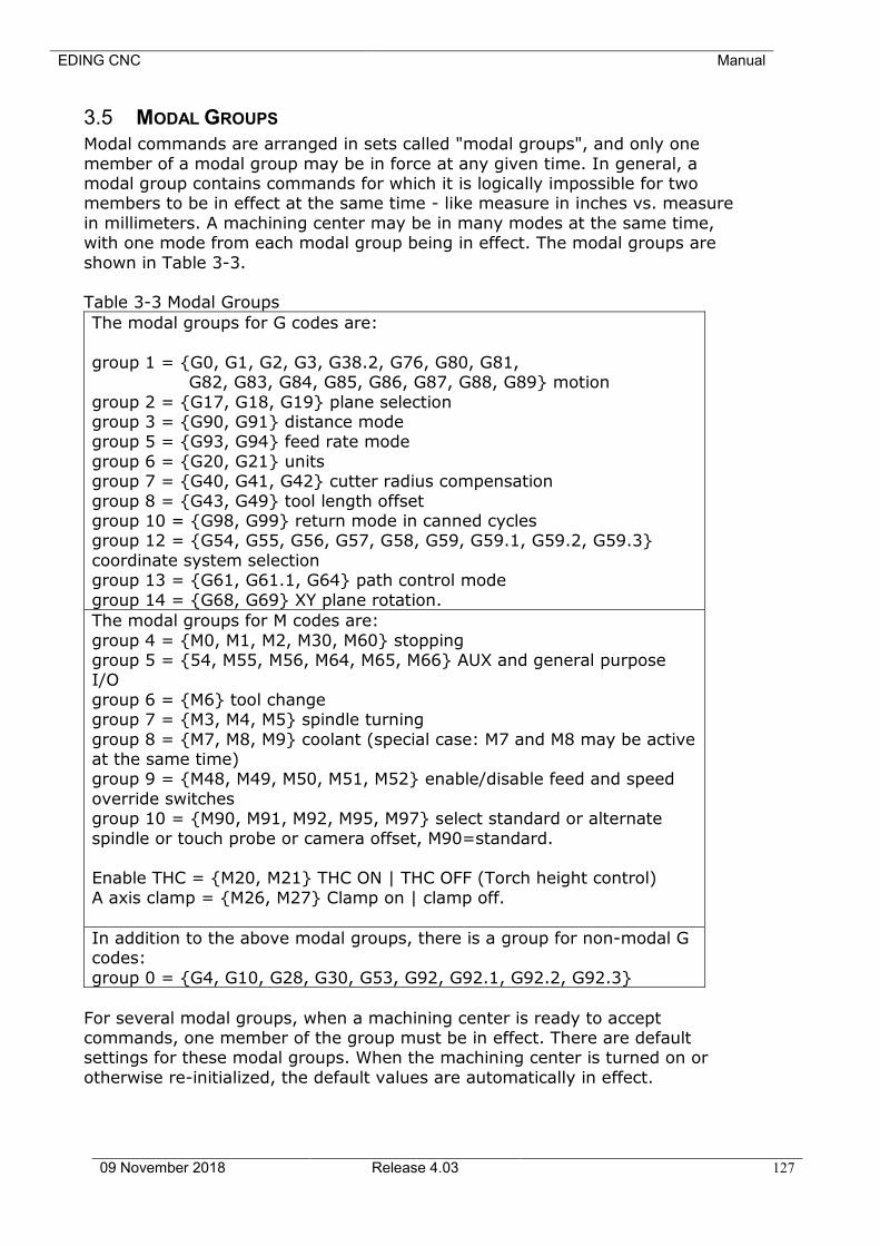
EDING CNC Manual
09 November 2018 Release 4.03 127
3.5 MODAL GROUPS
Modal commands are arranged in sets called "modal groups", and only one
member of a modal group may be in force at any given time. In general, a modal group contains commands for which it is logically impossible for two members to be in effect at the same time - like measure in inches vs. measure
in millimeters. A machining center may be in many modes at the same time, with one mode from each modal group being in effect. The modal groups are
shown in Table 3-3. Table 3-3 Modal Groups
The modal groups for G codes are:
group 1 = {G0, G1, G2, G3, G38.2, G76, G80, G81, G82, G83, G84, G85, G86, G87, G88, G89} motion
group 2 = {G17, G18, G19} plane selection group 3 = {G90, G91} distance mode group 5 = {G93, G94} feed rate mode
group 6 = {G20, G21} units group 7 = {G40, G41, G42} cutter radius compensation
group 8 = {G43, G49} tool length offset group 10 = {G98, G99} return mode in canned cycles group 12 = {G54, G55, G56, G57, G58, G59, G59.1, G59.2, G59.3}
coordinate system selection group 13 = {G61, G61.1, G64} path control mode
group 14 = {G68, G69} XY plane rotation.
The modal groups for M codes are:
group 4 = {M0, M1, M2, M30, M60} stopping group 5 = {54, M55, M56, M64, M65, M66} AUX and general purpose I/O
group 6 = {M6} tool change group 7 = {M3, M4, M5} spindle turning
group 8 = {M7, M8, M9} coolant (special case: M7 and M8 may be active at the same time) group 9 = {M48, M49, M50, M51, M52} enable/disable feed and speed
override switches group 10 = {M90, M91, M92, M95, M97} select standard or alternate
spindle or touch probe or camera offset, M90=standard. Enable THC = {M20, M21} THC ON | THC OFF (Torch height control)
A axis clamp = {M26, M27} Clamp on | clamp off.
In addition to the above modal groups, there is a group for non-modal G codes:
group 0 = {G4, G10, G28, G30, G53, G92, G92.1, G92.2, G92.3}
For several modal groups, when a machining center is ready to accept commands, one member of the group must be in effect. There are default settings for these modal groups. When the machining center is turned on or
otherwise re-initialized, the default values are automatically in effect.

EDING CNC Manual
09 November 2018 Release 4.03 128
Group 1, the first group on the table, is a group of G codes for motion. One of these is always in effect. That one is called the current motion mode.
It is an error to put a G-code from group 1 and a G-code from group 0 on the
same line if both of them use axis words. If an axis word-using G-code from group 1 is implicitly in effect on a line (by having been activated on an earlier line), and a group 0 G-code that uses axis words appears on the line, the
activity of the group 1 G-code is suspended for that line. The axis word-using G-codes from group 0 are G10, G28, G30, and G92.
EDING CNC Manual
09 November 2018 Release 4.03 129
3.6 G CODES
G codes of the RS274/NGC language are shown in Table 3-4 and described in
this Section. The descriptions contain command prototypes, set in bold type. In the command prototypes, three dots (…) stand for a real value. As described
earlier, a real value may be (1) an explicit number, 4, for example, (2) an expression, [2+2], for example, (3) a parameter value, #88, for example, or
(4) a unary function value, acos[0], for example. In most cases, if axis words (any or all of X…, Y…, Z…, A…, B…, C…) are given, they specify a destination point. Axis numbers are in the currently active
coordinate system, unless explicitly described as being in the absolute coordinate system. Where axis words are optional, any omitted axes will have
their current value. Any items in the command prototypes not explicitly described as optional are required. It is an error if a required item is omitted.
In the prototypes, the values following letters are often given as explicit numbers. Unless stated otherwise, the explicit numbers can be real values. For
example, G10 L2 could equally well be written G[2*5] L[1+1]. If the value of parameter 100 were 2, G10 L#100 would also mean the same. Using real values which are not explicit numbers as just shown in the examples is rarely
useful.
If L… is written in a prototype the "…" will often be referred to as the "L number". Similarly the "…" in H… may be called the "H number", and so on for any other letter.
3.6.1 Rapid Linear Motion - G0
For rapid linear motion, program G0 X… Y… Z… A…, where all the axis words are optional, except that at least one must be used. The G0 is optional if the
current motion mode is G0. This will produce coordinated linear motion to the destination point at the current traverse rate (or slower if the machine will not go that fast). It is expected that cutting will not take place when a G0 command
is executing.
It is an error if: • All axis words are omitted.
If cutter radius compensation is active, the motion will differ from the above; see Appendix A. If G53 is programmed on the same line, the motion will also
differ.
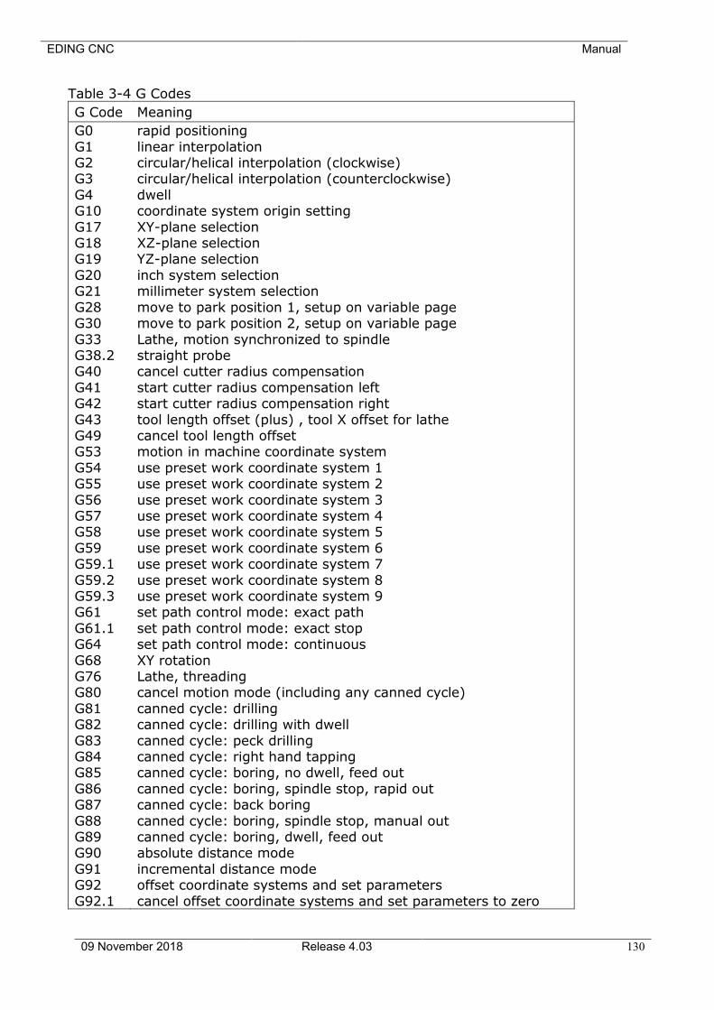
EDING CNC Manual
09 November 2018 Release 4.03 130
Table 3-4 G Codes
G Code Meaning
G0
G1 G2 G3
G4 G10
G17 G18 G19
G20 G21
G28 G30
G33 G38.2 G40
G41 G42
G43 G49 G53
G54 G55
G56 G57 G58
G59 G59.1
G59.2 G59.3 G61
G61.1 G64
G68 G76 G80
G81 G82
G83 G84 G85
G86 G87
G88 G89 G90
G91 G92
G92.1
rapid positioning
linear interpolation circular/helical interpolation (clockwise) circular/helical interpolation (counterclockwise)
dwell coordinate system origin setting
XY-plane selection XZ-plane selection YZ-plane selection
inch system selection millimeter system selection
move to park position 1, setup on variable page move to park position 2, setup on variable page
Lathe, motion synchronized to spindle straight probe cancel cutter radius compensation
start cutter radius compensation left start cutter radius compensation right
tool length offset (plus) , tool X offset for lathe cancel tool length offset motion in machine coordinate system
use preset work coordinate system 1 use preset work coordinate system 2
use preset work coordinate system 3 use preset work coordinate system 4 use preset work coordinate system 5
use preset work coordinate system 6 use preset work coordinate system 7
use preset work coordinate system 8 use preset work coordinate system 9 set path control mode: exact path
set path control mode: exact stop set path control mode: continuous
XY rotation Lathe, threading cancel motion mode (including any canned cycle)
canned cycle: drilling canned cycle: drilling with dwell
canned cycle: peck drilling canned cycle: right hand tapping canned cycle: boring, no dwell, feed out
canned cycle: boring, spindle stop, rapid out canned cycle: back boring
canned cycle: boring, spindle stop, manual out canned cycle: boring, dwell, feed out absolute distance mode
incremental distance mode offset coordinate systems and set parameters
cancel offset coordinate systems and set parameters to zero
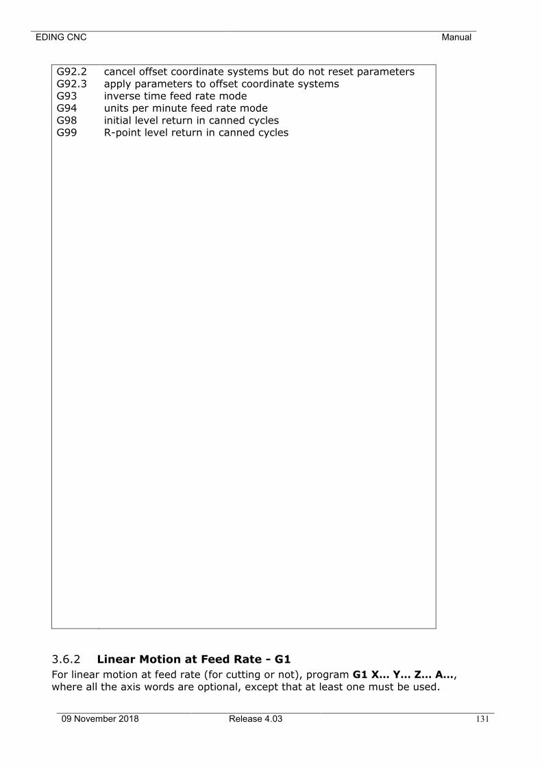
EDING CNC Manual
09 November 2018 Release 4.03 131
G92.2
G92.3 G93 G94
G98 G99
cancel offset coordinate systems but do not reset parameters
apply parameters to offset coordinate systems inverse time feed rate mode units per minute feed rate mode
initial level return in canned cycles R-point level return in canned cycles
3.6.2 Linear Motion at Feed Rate - G1
For linear motion at feed rate (for cutting or not), program G1 X… Y… Z… A…,
where all the axis words are optional, except that at least one must be used.
EDING CNC Manual
09 November 2018 Release 4.03 132
The G1 is optional if the current motion mode is G1. This will produce coordinated linear motion to the destination point at the current feed rate (or
slower if the machine will not go that fast).
It is an error if: • All axis words are omitted.
If cutter radius compensation is active, the motion will differ from the above; see Appendix A. If G53 is programmed on the same line, the motion will also
differ.
3.6.3 Arc at Feed Rate - G2 and G3
A circular or helical arc is specified using either G2 (clockwise arc) or G3 (counterclockwise arc). The axis of the circle or helix must be parallel to the X,
Y, or Z-axis of the machine coordinate system. The axis (or, equivalently, the plane perpendicular to the axis) is selected with G17 (Z-axis, XY-plane), G18 (Y-
axis, XZ-plane), or G19 (X-axis, YZ-plane). If the arc is circular, it lies in a plane parallel to the selected plane.
If a line of RS274/NGC code makes an arc and includes rotational axis motion, the rotational axes turn at a constant rate so that the rotational motion starts
and finishes when the XYZ motion starts and finishes. Lines of this sort are hardly ever programmed. If cutter radius compensation is active, the motion will differ from what is
described here. See Appendix A.
Two formats are allowed for specifying an arc. We will call these the center format and the radius format. In both formats the G2 or G3 is optional if it is the current motion mode.
3.6.3.1 RADIUS FORMAT ARC
In the radius format, the coordinates of the end point of the arc in the selected plane are specified along with the radius of the arc. Program G2 X… Y… Z… A… R… (or use G3 instead of G2). R is the radius. The axis words are all
optional except that at least one of the two words for the axes in the selected plane must be used. The R number is the radius. A positive radius indicates that
the arc turns through 180 degrees or less, while a negative radius indicates a turn of 180 degrees to 359.999 degrees. If the arc is helical, the value of the end point of the arc on the coordinate axis parallel to the axis of the helix is also
specified.
It is not good practice to program radius format arcs that are nearly full circles or are semicircles (or nearly semicircles) because a small change in the location of the end point will produce a much larger change in the location of the center
of the circle (and, hence, the middle of the arc). The magnification effect is large enough that rounding error in a number can produce out-of-tolerance
cuts. Nearly full circles are outrageously bad, semicircles (and nearly so) are only very bad. Other size arcs (in the range tiny to 165 degrees or 195 to 345 degrees) are OK.
EDING CNC Manual
09 November 2018 Release 4.03 133
Here is an example of a radius format command to mill an arc: G17 G2 x 10 y 15 r 20 z 5.
That means to make a clockwise (as viewed from the positive Z-axis) circular or
helical arc whose axis is parallel to the Z-axis, ending where X=10, Y=15, and Z=5, with a radius of 20. If the starting value of Z is 5, this is an arc of a circle parallel to the XY-plane; otherwise it is a helical arc.
3.6.3.2 CENTER FORMAT ARC
In the center format, the coordinates of the end point of the arc in the selected plane are
specified along with the offsets of the center of the arc from the current location. In this format, it is OK if the end point of the arc is the same as the
current point. It is an error if:
• When the arc is projected on the selected plane, the distance from the
current point to the center differs from the distance from the end point to the center by more than 0.0002 inch (if inches are being used) or 0.002
millimeter (if millimeters are being used). When the XY-plane is selected, program G2 X… Y… Z… A… I… J… (or use G3
instead of G2). The axis words are all optional except that at least one of X and Y must be used. I and J are the offsets from the current location (in the X and Y
directions, respectively) of the center of the circle. I and J are optional except that at least one of the two must be used. It is an error if:
• I and J are both omitted.
When the XZ-plane is selected, program G2 X… Y… Z… A… I… K… (or use G3
instead of G2). The axis words are all optional except that at least one of X and Z must be used. I and K are the offsets from the current location (in the X and Z directions, respectively) of the center of the circle. I and K are optional except
that at least one of the two must be used. It is an error if: • I and K are both omitted.
When the YZ-plane is selected, program G2 X… Y… Z… A… B… C… J… K… (or use G3 instead of G2). The axis words are all optional except that at least
one of Y and Z must be used. J and K are the offsets from the current location (in the Y and Z directions, respectively) of the center of the circle. J and K are
optional except that at least one of the two must be used. It is an error if: • J and K are both omitted.
Here is an example of a center format command to mill an arc: G17 G2 x10 y16 i3 j4 z9.
That means to make a clockwise (as viewed from the positive z-axis) circular or
helical arc whose axis is parallel to the Z-axis, ending where X=10, Y=16, and Z=9, with its center offset in the X direction by 3 units from the current X location and offset in the Y direction by 4 units from the current Y location. If
the current location has X=7, Y=7 at the outset, the center will be at X=10, Y=11. If the starting value of Z is 9, this is a circular arc; otherwise it is a
helical arc. The radius of this arc would be 5.
EDING CNC Manual
09 November 2018 Release 4.03 134
In the center format, the radius of the arc is not specified, but it may be found
easily as the distance from the center of the circle to either the current point or the end point of the arc.
3.6.4 Dwell - G4
For a dwell, program G4 P… . This will keep the axes unmoving for the period of time in seconds specified by the P number. It is an error if:
• the P number is negative.
3.6.5 Set Coordinate System Data -G10
To set the coordinate values for the origin of a coordinate system, program G10 L2 P … X… Y… Z… A…, where the P number must evaluate to an integer
in the range 1 to 9 (corresponding to G54 to G59.3) and all axis words are optional. The coordinates of the origin of the coordinate system specified by the P number are reset to the coordinate values given (in terms of the absolute
coordinate system). Only those coordinates for which an axis word is included on the line will be reset.
It is an error if:
• the P number does not evaluate to an integer in the range 1 to 9.
If origin offsets (made by G92 or G92.3) were in effect before G10 is used, they
will continue to be in effect afterwards. The coordinate system whose origin is set by a G10 command may be active or
inactive at the time the G10 is executed. Example:G10 L2 P1 x 3.5 y 17.2 sets the origin of the first coordinate system
(the one selected by G54) to a point where X is 3.5 and Y is 17.2 (in absolute coordinates). The Z coordinate of the origin (and the coordinates for any rotational axes) are whatever those coordinates of the origin were before the
line was executed.
G10 L20 P.. X.. Y.. Z.. A.. Set coordinate system given by P number relative to actual machine position.
Working is similar to G92. Jog to any position, then apply e.g. G10 L20 P1 X0 Y0 to set G54 coordinate system zero point at current machine position.
3.6.6 Plane Selection - G17, G18, and G19
Program G17 to select the XY-plane, G18 to select the XZ-plane, or G19 to select the YZ-plane.
3.6.7 Length Units - G20/G21 and G70/G71
Program G20 to use inches for length units. Program G21 to use millimeters.
EDING CNC Manual
09 November 2018 Release 4.03 135
It is usually a good idea to program either G20 or G21 near the beginning of a program before any motion occurs, and not to use either one anywhere else in
the program. It is the responsibility of the user to be sure all numbers are appropriate for use with the current length units. G70/G71 is added for CAM
software compatibility.
3.6.8 Return to Home - G28 and G30
Two home positions are defined (by parameters 5161-5166 for G28 and parameters
5181-5186 for G30). The parameter values are in terms of the absolute coordinate system, but are in unspecified length units.
To return to home position by way of the programmed position, program G28 X… Y… Z… A… (or use G30). All axis words are optional. The path is made by a traverse move from the current position to the programmed position,
followed by a traverse move to the home position. If no axis words are programmed, the intermediate point is the current point, so only one move is
made. The order of Z depends on its position, if the end position is higher as the current Z position Z will move first, otherwise Z will move last, this is to prevent collision.
Addition for lathe: For lathe the X axis is moved first, assumption is that X
moves away from the turning center.
EDING CNC Manual
09 November 2018 Release 4.03 136
3.6.9 G33, G33.1 Spindle-Synchronized Motion
For spindle-synchronized motion in one direction, program G33 X… Y… Z… K… where K gives the distance moved in XYZ for each revolution of the spindle.
For G33 the software performs this:
1. Start a synchronized move with spindle with K feed per revolution. Assumed is that the spindle already runs (M3).
2. Done.
For G33.1 the software performs:
1. Start a synchronized move with spindle with K feed per revolution. Assumed is that the spindle is running (M3).
2. Wait until this motion is done.
3. Reverse spindle direction. 4. Move back to original position where we were before the G33.1.
5. Done
All the axis words are optional, except that at least one must be used. It is an error if:
• all axis words are omitted. • the spindle is not turning when this command is executed. • the requested linear motion exceeds machine velocity limits due to the
spindle speed.
EDING CNC Manual
09 November 2018 Release 4.03 137
3.6.10 Straight Probe - G38.2
3.6.10.1 THE STRAIGHT PROBE COMMAND
Program G38.2 X… Y… Z… A… to perform a straight probe operation. The
rotational axis words are allowed, but it is better to omit them. If rotational axis words are used, the numbers must be the same as the current position numbers so that the rotational axes do not move. The linear axis words are optional,
except that at least one of them must be used. The tool in the spindle must be a probe.
It is an error if: • the current point is less than 0.254 millimeter or 0.01 inch from the pro-
grammed point.
• G38.2 is used in inverse time feed rate mode, • any rotational axis is commanded to move,
• no X, Y, or Z-axis word is used.
In response to this command, the machine moves the controlled point (which should be at the end of the probe tip) in a straight line at the current feed rate toward the programmed point. If the probe trips, the probe is retracted slightly
from the trip point at the end of command execution. If the probe does not trip even after overshooting the programmed point slightly, an error is signaled.
After successful probing, parameters 5061 to 5066 will be set to the program coordinates of the location of the controlled point at the time the probe tripped.
The variables 5051 to 5056 will contain the machine coordinates. Useful for measuring tools in absolute machine positions. G53 G38.2 will move in machine
coordinates.
3.6.10.2 USING THE STRAIGHT PROBE COMMAND
Using the straight probe command, if the probe shank is kept nominally parallel to the Z-axis (i.e., any rotational axes are at zero) and the tool length offset for the probe is used, so that the controlled point is at the end of the tip of the
probe: • without additional knowledge about the probe, the parallelism of a face of
a part to the XY-plane may, for example, be found. • if the probe tip radius is known approximately, the parallelism of a face of
a part to the YZ or XZ-plane may, for example, be found. • if the shank of the probe is known to be well-aligned with the Z-axis and
the probe tip radius is known approximately, the center of a circular hole,
may, for example, be found. • if the shank of the probe is known to be well-aligned with the Z-axis and
the probe tip radius is known precisely, more uses may be made of the straight probe command, such as finding the diameter of a circular hole.
If the straightness of the probe shank cannot be adjusted to high accuracy, it is desirable to know the effective radii of the probe tip in at least the +X, -X, +Y,
and -Y directions. These quantities can be stored in parameters either by being included in the parameter file or by being set in an RS274/NGC program. Using the probe with rotational axes not set to zero is also feasible. Doing so is
more complex than when rotational axes are at zero, and we do not deal with it here.

EDING CNC Manual
09 November 2018 Release 4.03 138
3.6.10.3 EXAMPLE CODE
As a usable example, the code for finding the center and diameter of a circular hole is shown in Table 3-5. For this code to yield accurate results, the probe
shank must be well-aligned with the Z-axis, the cross section of the probe tip at its widest point must be very circular, and the probe tip radius (i.e., the radius of the circular cross section) must be known precisely. If the probe tip radius is
known only approximately (but the other conditions hold), the location of the hole center will still be accurate, but the hole diameter will not.
In Table 3-5, an entry of the form <description of number> is meant to be replaced by an actual number that matches the description of number. After this
section of code has executed, the X-value of the center will be in parameter 1041, the Y-value of the center in parameter 1022, and the diameter in
parameter 1034. In addition, the diameter parallel to the X-axis will be in parameter 1024, the diameter parallel to the Y-axis in parameter 1014, and the difference (an indicator of circularity) in parameter 1035. The probe tip will be in
the hole at the XY center of the hole.
The example does not include a tool change to put a probe in the spindle. Add the tool change code at the beginning, if needed.
Table 3-5 Code to Probe Hole
N010 (probe to find center and diameter of circular hole) N020 (This program will not run as given here. You have to)
N030 (insert numbers in place of <description of number>.) N040 (Delete lines N020, N030, and N040 when you do that.) N050 G0 Z <Z-value of retracted position> F <feed rate>
N060 #1001=<nominal X-value of hole center> N070 #1002=<nominal Y-value of hole center>
N080 #1003=<some Z-value inside the hole> N090 #1004=<probe tip radius> N100 #1005=[<nominal hole diameter>/2.0 - #1004]
N110 G0 X#1001 Y#1002 (move above nominal hole center) N120 G0 Z#1003 (move into hole - to be cautious, substitute G1 for G0
here) N130 G38.2 X[#1001 + #1005] (probe +X side of hole) N140 #1011=#5061 (save results)
N150 G0 X#1001 Y#1002 (back to center of hole) N160 G38.2 X[#1001 - #1005] (probe -X side of hole)
N170 #1021=[[#1011 + #5061] / 2.0] (find pretty good X-value of hole center) N180 G0 X#1021 Y#1002 (back to center of hole)
N190 G38.2 Y[#1002 + #1005] (probe +Y side of hole) N200 #1012=#5062 (save results) N210 G0 X#1021 Y#1002 (back to
center of hole) N220 G38.2 Y[#1002 - #1005] (probe -Y side of hole)
N230 #1022=[[#1012 + #5062] / 2.0] (find very good Y-value of hole center)
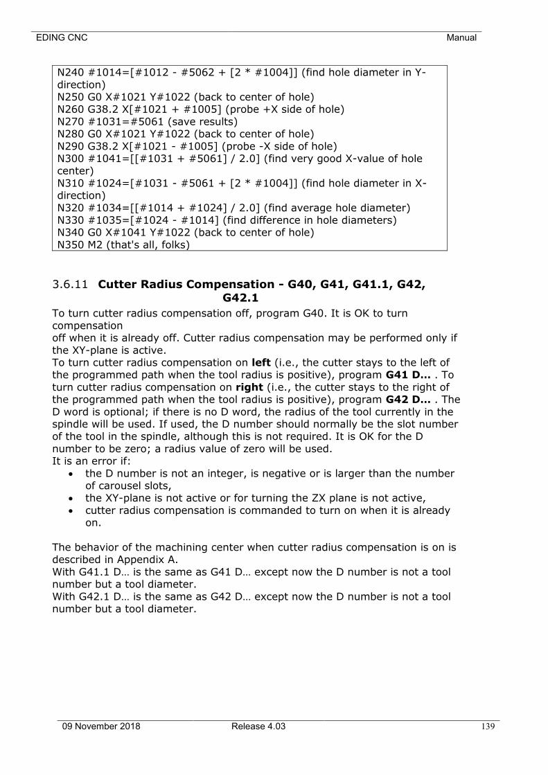
EDING CNC Manual
09 November 2018 Release 4.03 139
N240 #1014=[#1012 - #5062 + [2 * #1004]] (find hole diameter in Y-
direction) N250 G0 X#1021 Y#1022 (back to center of hole) N260 G38.2 X[#1021 + #1005] (probe +X side of hole)
N270 #1031=#5061 (save results) N280 G0 X#1021 Y#1022 (back to center of hole)
N290 G38.2 X[#1021 - #1005] (probe -X side of hole) N300 #1041=[[#1031 + #5061] / 2.0] (find very good X-value of hole center)
N310 #1024=[#1031 - #5061 + [2 * #1004]] (find hole diameter in X-direction)
N320 #1034=[[#1014 + #1024] / 2.0] (find average hole diameter) N330 #1035=[#1024 - #1014] (find difference in hole diameters) N340 G0 X#1041 Y#1022 (back to center of hole)
N350 M2 (that's all, folks)
3.6.11 Cutter Radius Compensation - G40, G41, G41.1, G42,
G42.1
To turn cutter radius compensation off, program G40. It is OK to turn
compensation off when it is already off. Cutter radius compensation may be performed only if
the XY-plane is active. To turn cutter radius compensation on left (i.e., the cutter stays to the left of the programmed path when the tool radius is positive), program G41 D… . To
turn cutter radius compensation on right (i.e., the cutter stays to the right of the programmed path when the tool radius is positive), program G42 D… . The
D word is optional; if there is no D word, the radius of the tool currently in the spindle will be used. If used, the D number should normally be the slot number of the tool in the spindle, although this is not required. It is OK for the D
number to be zero; a radius value of zero will be used. It is an error if:
• the D number is not an integer, is negative or is larger than the number of carousel slots,
• the XY-plane is not active or for turning the ZX plane is not active,
• cutter radius compensation is commanded to turn on when it is already on.
The behavior of the machining center when cutter radius compensation is on is described in Appendix A.
With G41.1 D… is the same as G41 D… except now the D number is not a tool number but a tool diameter.
With G42.1 D… is the same as G42 D… except now the D number is not a tool number but a tool diameter.

EDING CNC Manual
09 November 2018 Release 4.03 140
3.6.11.1 EXAMPLE CODE FOR MILLING
This example mills out a rectangular
object from the outside and inside. On the outside we use G42, tool radius compensation right and for the
inside G41, tool radius compensation left is used.
For both contours a tool-radius-compensation entry move is
programmed consisting of a line which must be longer than the tool-radius used and a circle, of which also
the radius is bigger than the tool.
By the way, all arc radii should be bigger than the tool radius. If you have inside corners, there should be
always an arc, so that the tool fits.
g0 z3
g0 x-15 y15 f500 /g42.1 D6
g1 x-5 (cutter comp entry move 1)
g2 x0 y10 r5 (cutter comp entry move 2) g1 z-3 (plunge down)
g3 x10 y0 r10 g1 x70
g3 x80 y10 r10 g1 y90 g3 x70 y100 r10
g1 x10 g3 x0 y90 r10
g1 x0 y10 /g40 g0 z3
g0 x30 y30 /g41.1 d6
g1 x20 g3 x10 y20 r10 g1 z-3
g3 x20 y10 r10 g1 x60
g3 x70 y20 r10 g1 y80 g3 x60 y90 r10
The G42, G41 and G40 codes are
programmed with a / (block delete sign) in front. This makes it easy to debug tool comp programs. The
program is loaded with block delete on, this is the blue curve.
Then the program is run with block delete off resulting in the yellow curve.
It is clear to see what the entry move
does.

EDING CNC Manual
09 November 2018 Release 4.03 141
g1 x20
g3 x10 y80 r10 g1 y20 /g40
g0 z3 m30
3.6.11.2 EXAMPLE CODE FOR TURNING
The movement starts at the right upper corner.
The blue line is the programmed contour. The
yellow is the contour with tool-radius compensation G41.
The first G1 line is the tool comp entry move.
You can get this figure by
putting a / character in front of the G41/G40 codes. The load the program with
block delete on and execute it with block delete off. With
block delete on the tool comp is skipped.
(Diameter programming) (Use R word for Arcs) g0 x-20 z20
/g41.1 d5 g1 x-20 z10
g3 x0 z0 r10 g1 x20 g2 x40 z-10 r10
g1 z-20 g3 x60 z-30 r10
/g40 m30
(Radius programming) (Use R word for arc’s) g0 x-10 z20
/g41.1 d5 g1 x-10 z10
g3 x0 z0 r10 g1 x10 g2 x20 z-10 r10
g1 z-20 g3 x30 z-30 r10
/g40 m30
(Diameter programming) (Use I,K programming for arc’s) g0 x-20 z20
/g41.1 d5 g1 x-20 z10
g3 x0 z0 i10 k0 g1 x20 g2 x40 z-10 i0 k-10
g1 z-20 g3 x60 z-30 i10 k0
/g40 m30
(Radius programming) (Use I,K programming for arc’s)
g0 x-10 z20 /g41.1 d5
g1 x-10 z10 g3 x0 z0 i10 k0 g1 x10
g2 x20 z-10 i0 k-10 g1 z-20
g3 x30 z-30 i10 k0 /g40

EDING CNC Manual
09 November 2018 Release 4.03 142
m30
EDING CNC Manual
09 November 2018 Release 4.03 143
3.6.12 Tool Length Offsets - G43, G43 H, G43.1, and G49
A. To use the tool offset of the tool in the spindle use G43. This assures that always the tool length of the tool in spindle is compensated.
B. To use a tool length offset from the tool table, program G43 H…, where the
H number is the desired index in the tool table. ( H = 1 - 99) C. To use dynamic tool compensation (not from the tool-table), use G43.1 I.. K..
where I.. gives the tool X offset (turning) and K.. gives the tool Z offset (for turning and milling)
Warning: If you use option B or C, the tool-length compensation will not adapt to the new tool after M6T...
To have no tool length offset compensation, program G49
#5401 - #5499 is the tool-length of tool 1-99 #5501 - #5599 is the tool-diameter of tool 1-99
#5601 - #5699 is the tool-xoffset (width for turning) offset.
The variables can be modified runtime (in the G-Code file) if needed to compensate for tool-wear.
3.6.13 Scaling G50/G51
G50 scaling off.
UNIFORM Scaling G51 P.. I.. J.. P is scaling factor.
NON UNIFORM Scaling (X,Y different, only applicable when NO Arcs)
G51 X.. Y.. I.. J.. X is scaling factor for X coordinates. Y is scaling factor for Y coordinates.
I is X coordinate scaling point
J is Y coordinate scaling point When used in combination with G68, the rotation point and scaling point are the
same.
EDING CNC Manual
09 November 2018 Release 4.03 144
3.6.14 Move in Absolute Coordinates - G53
For linear motion to a point expressed in absolute coordinates, program G1 G53 X… Y… Z… A… (or use G0 instead of G1), where all the axis words are optional, except that at least one must be used. The G0 or G1 is optional if it is
the current motion mode. G53 is not modal and must be programmed on each line on which it is intended to be active. This will produce coordinated linear
motion to the programmed point. If G1 is active, the speed of motion is the current feed rate (or slower if the machine will not go that fast). If G0 is active, the speed of motion is the current traverse rate (or slower if the machine will
not go that fast).
It is an error if: • G53 is used without G0 or G1 being active, • G53 is used while cutter radius compensation is on.
3.6.15 Select Coordinate System - G54 to G59.3
To select coordinate system 1, program G54, and similarly for other coordinate systems. The system-number-G-code pairs are: (1-G54), (2-G55), (3-G56), (4-
G57), (5-G58), (6-G59), (7-G59.1), (8-G59.2), and (9-G59.3). It is an error if:
• one of these G-codes is used while cutter radius compensation is on.

EDING CNC Manual
09 November 2018 Release 4.03 145
3.6.16 Path Control Mode and Look ahead feed- G61, and G64
Ideally one would like to have constant cutting speed during the work and maximum accuracy. This ideal is physically not possible, similar as driving a racecar on curvy roads is not possible with constant velocity. It is simply to
understand that it is needed to brake in the curves and accelerate on the straight roads. If you would do the same speed in the curves as on the straight
road, the car will fly out of the curve and get an accident. With a CNC machine it is the similar, constant speed and accuracy together are physically not possible. It would require infinite acceleration to go through a corner from one direction
to another. In a CNC machine this would result in position/step loss of stepper motors or high following error with servo’s. If the motion path to consist of
small lines (G1) it is even worse than driving a racecar, because there is a sharp corner between every line. This is often the case with CAM generated motion paths (g-code).
So a compromise has to be made. There are various options to choose the
optimum between accuracy and constant speed or fast speed versus jerkiness. G61 puts the machining center into exact path mode, In G61, the motion
velocity between motion segments goes to zero, the end position in corners is exactly reached, use this if you require maximum accuracy. When a work piece
consists of many small lines this gives a quite jerky/vibrating machine because of the continuous acceleration-deceleration-stop behavior. More practical is to use G64 and G64 P.. , see below.
G64
G64 is to be used for more smooth and fast motion. There are 4 parameters that can be used, they are explained below individually but the can be combined on one line.
G64 without further parameters switches on continuous/smooth velocity mode.
In G64, subsequent moves are blended, when previous move starts to decelerate and reaches a velocity such that the specified accuracy isn’t violated,
the next move starts to accelerate, the two motions are added. The result is smooth motion with highest constant speed. The corners however are rounded. The amount of rounding is depending on the max acceleration of the machine.
The higher the acceleration, the less rounding.
G64 P.. The optional P value specifies the distance reached to the corner while blending. The next move is blended with current such that the tool path remains no more
than P from the corner. This will cause a velocity ramp down in the corner but not to zero. The figure below is a rectangle of 10x10 milled with F 2000. This is
done with P values from 0.1 to 1, you can see the impact. This gives the best compromise between accuracy and smooth motion. So you can say G64 P.. is like a compromise between G61 and G64 without P.
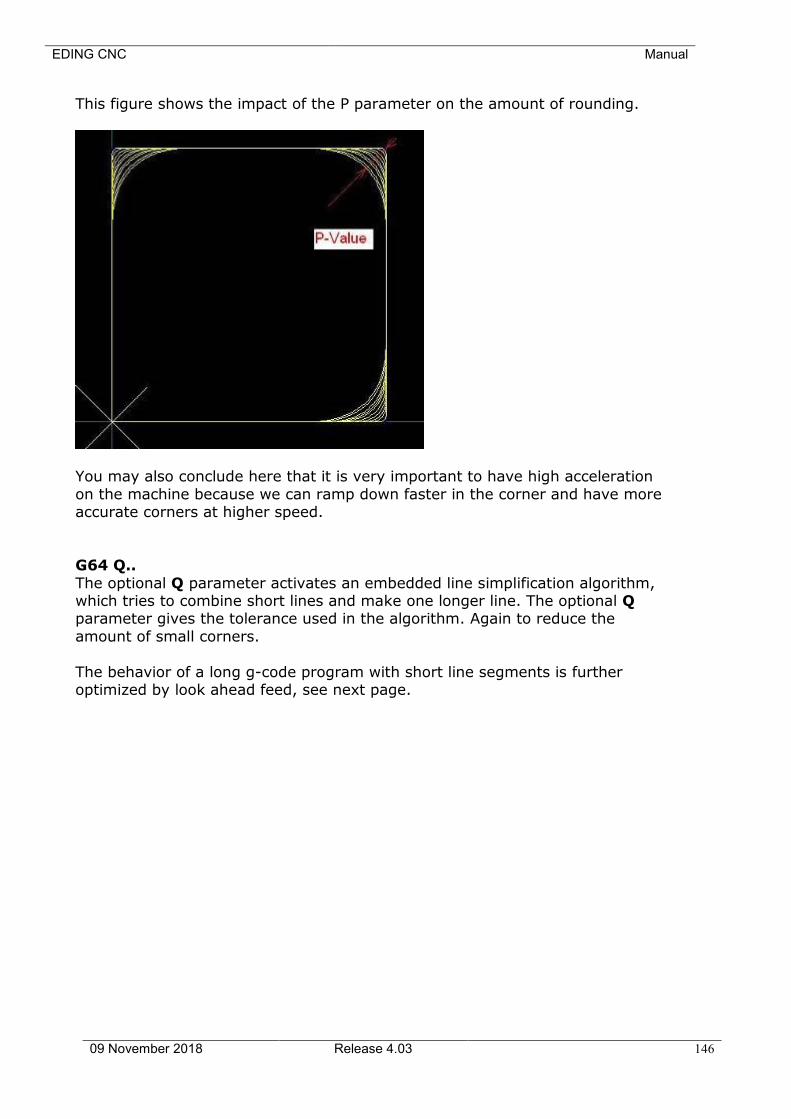
EDING CNC Manual
09 November 2018 Release 4.03 146
This figure shows the impact of the P parameter on the amount of rounding.
You may also conclude here that it is very important to have high acceleration
on the machine because we can ramp down faster in the corner and have more accurate corners at higher speed.
G64 Q..
The optional Q parameter activates an embedded line simplification algorithm, which tries to combine short lines and make one longer line. The optional Q parameter gives the tolerance used in the algorithm. Again to reduce the
amount of small corners.
The behavior of a long g-code program with short line segments is further optimized by look ahead feed, see next page.
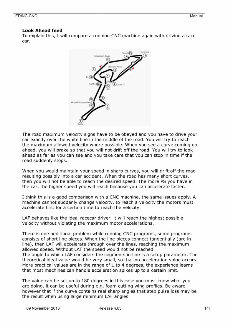
EDING CNC Manual
09 November 2018 Release 4.03 147
Look Ahead feed To explain this, I will compare a running CNC machine again with driving a race
car.
The road maximum velocity signs have to be obeyed and you have to drive your
car exactly over the white line in the middle of the road. You will try to reach the maximum allowed velocity where possible. When you see a curve coming up
ahead, you will brake so that you will not drift off the road. You will try to look ahead as far as you can see and you take care that you can stop in time if the road suddenly stops.
When you would maintain your speed in sharp curves, you will drift off the road
resulting possibly into a car accident. When the road has many short curves, then you will not be able to reach the desired speed. The more PS you have in the car, the higher speed you will reach because you can accelerate faster.
I think this is a good comparison with a CNC machine, the same issues apply. A
machine cannot suddenly change velocity, to reach a velocity the motors must accelerate first for a certain time to reach the velocity.
LAF behaves like the ideal racecar driver, it will reach the highest possible velocity without violating the maximum motor accelerations.
There is one additional problem while running CNC programs, some programs
consists of short line pieces. When the line pieces connect tangentially (are in line), then LAF will accelerate through over the lines, reaching the maximum allowed speed. Without LAF the speed would not be reached.
The angle to which LAF considers the segments in line is a setup parameter. The theoretical ideal value would be very small, so that no acceleration value occurs.
More practical values are in the range of 1 to 4 degrees, the experience learns that most machines can handle acceleration spikes up to a certain limit.
The value can be set up to 180 degrees in this case you must know what you are doing, it can be useful during e.g. foam cutting wing profiles. Be aware
however that if the curve contains real sharp angles that step pulse loss may be the result when using large minimum LAF angles.
EDING CNC Manual
09 November 2018 Release 4.03 148
In practice we have seen that milling times of complex 3D work pieces can be
done in 50% of the time compared to competitors who do not have LAF.
With G64 R.. the LAF angle can be changed in the g-code file, see explanation of G64 and G61. The standard LAF angle is in the software set-up. To give some realistic values: A value of 3 is good for most machines. A value of
6 may already give too much Jerky ness on some machines. Still there are customers using values of 20 here, but they have quite specific machine
constructions and application e.g. dental milling. G64 F..
The F parameter defines the value of the Accel/Decel filter placed behind LAF.
LAF with high R values (Angle) can cause acceleration spikes because LAF will travel through corners without stopping. The F parameter filters the trajectory generated by LAF and takes care the acceleration is never violated.
F1 will give a RAMP time that matches with the max velocity / max acceleration from the setup and so F1 and maximum speed will lead to the max max
acceleration that is allowed. Smaller F values filter less. This can be used if the milling velocity is less than the max velocity of the machine. Example:
Max velocity in the setup is 200 and used milling velocity is F6000 (100 mm/s), Then F0.5 is safe to use. So now you can do this G64 R100 F1 and you will not get acceleration spikes but very smooth an fast movement. The price to pay is
corner rounding which is depending on the max acceleration of the machine, the higher the max acceleration, the less corner rounding.
A good application example is with milling rubber or similar flexible material, the milling speed must be constant otherwise more material is removed in the corners due to the lower speed and the flexibility of the rubber. The F1 in
combination with R100 will give constant and high speed for good milling surface quality of the rubber.
Application F: For milling e.g. rubber when constant speed is more important than rounding. To have an acceptable amount of rounding the machine needs to
have very high acceleration. This function was tested and used on a machine with relative low speed (100 mm/sec) and very high acceleration (4000 mm/sec
* sec).
G64 R..
The R parameter is the look-ahead feed angle, when subsequent lines/arcs have an angle together less than this value, the trajectory-generator will accelerate
through over these segments and this way optimizes the production time. With R0, LAF is switched off, with LAF off a (much) lower but more constant speed is
achieved. The higher the angle, the higher the speed, but the jerkier for the machine because high accel peaks. This needs to be tuned depending on the quality of the machine and the power of the used motors.
A compromise is to be found between speed and machine behavior.

EDING CNC Manual
09 November 2018 Release 4.03 149
G64 R.. S.. D.. (NEW for V4.03.xx)
New algorithm: With the standard LAF setting G64 R.. (no S.. andno D..), the velocity in corners
will be zero when the angle between the segments is bigger than LAF angle in the set-up. But there are angles that are big and also smaller angles, so we were seeking for and found a solution where depending on the angle size, the
speed in the corner the velocity is limited but not to zero and further limited if the angle gets bigger. This allows faster production especially for 3D work.
Putting a circle to the original path would be a solution. But this cannot be done in real-time and is also not always wanted because we want the contour to be
milled as specified in the g-code. Still we could calculate a circle between 2 segments when knowing its start and
end vector. The circle radius could then be used to calculate an allowable velocity in the corner taking the max acceleration into account like this:
Vcorner = SQRT ( Amax * R) Where A max is the maximum possible acceleration which is known by the setup
and R is the calculated Radius depending on the angle between the segments and the D value supplied in the G64 command.
This is basically the idea. If we draw it, it gets more clear:
Segment 1 and segment 2 are 2 subsequent motion segments.
Alfa is the change of direction angle between the segments. Beta is the angle between the lines to fit the circle.
D is the user supplied max deviation between junction and the circle, this determines how far the junction speed is limited. R is the calculated radius from D and Beta.
So D is the parameter that determines the amount of speed reduction in the corner. Practical values are in the order of 0.01 .. 0.0001 for D. The smaller the
value the smaller the circle radius, the smaller the velocity in the corner.
D
Segment 1, V1
Segment 2, V2
R
Alfa
Beta
EDING CNC Manual
09 November 2018 Release 4.03 150
This value needs to be tuned by experimenting on the target machine, if the value is too high the machine will move jerky. Note that the corner is not
actually traveled, the original path is traveled, but the corner velocity is limited as if there was an arc between the segments.
Both new and old algorithm co-exist in the proto software. So the user can specify 2 angles and the D parameters now with G64 together with existing P
parameter.
G64 P.. R.. S.. D.. P: Parameter for max rounding when blending
R: LAF angle for standard algorithm where LAF will travel full speed of angle is lower.
S: 2nd angle, the new algorithm will work between the R.. angle and S.. angle. D: deviation of virtual circle in the corner used in the algorithm.
Example: G64 P0.1 R3 S90 D0.001
Full speed when angle is less than R angle. Reduced speed depending on D when angle is between the R and S angle. For
angles bigger than S.. angle blending kicks in and uses the P.. as tolerance.
G64 P.. Q.. R.. S.. D.. F.. There are 6 parameters which can be combined with G64.
For normal milling, mostly G64 P.. is used.

EDING CNC Manual
09 November 2018 Release 4.03 151
3.6.17 Coordinate system rotation G68
G68 X.. Y.. Z.. I.. J.. K.. R..
X.. Y.. Z.. : Optional Specifies to rotation point, if not given, the current Work Zero point is used.
I.. J.. K.. : Optional, without I J K the rotation takes place in the actual
PLANE G17/G18/G19. Either I1 or J1 or K1 can be used, not a
combination. I1 rotation about X in YZ plane, J1 rotation about Y in XZ plane,
K1 rotation about Z in XY plane. R Rotation angle in degrees, positive is counter-clockwise, negative is clockwise.
X Y Rotation point in current coordinate system.
Use G69 to switch off G68.
3.6.18 Threading (Lathe) – G76
G76 P- Z- I- J- R- K- Q- H- E- L-
P Pitch Z driveline endpoint I Outside thread diameter, always positive.
J First cut is J beyond I, always positive. R Depth regression, use 1.0 for constant cutting depths or leave parameter
away. K Full thread depth beyond thread peak, always positive. Q Compound slide angle, typical 30.
H Additional spring passes at full depth, use 0 for none. E Taper distance along drive line.
L Taper place, none, enter, exit, both.
;Create a thread from z=20 to z=10, outside diameter=15, inside diameter=14, 10 passes. G0 X20 Z20
G76 P1.0 Z10 I15 J0.1 K1.0
It is an error if:
• The active plane is not the ZX plane • Other axis words, such as X- or Y-, are specified
• The R- degression value is less than 1.0. • All the required words are not specified
• P-, J-, K- or H- is negative • E- is greater than half the drive line length
EDING CNC Manual
09 November 2018 Release 4.03 152
The “drive line” is a safe line outside the thread material. The “drive line” goes from the initial location to the Z- value specified with G76. The Z extent of the
thread is the same as the drive line.
The “thread pitch”, or distance per revolution, is given by the P- value.
The “thread peak” is given by the I- value, which is an offset from the drive line. Negative I values indicate external threads, and positive I values indicate
internal threads. Generally the material has been turned to this size before the G76 cycle.
The “initial cut depth” is given by the J- value. The first threading cut will be J
beyond the “thread peak” position. J- is positive, even when I- is negative.
The “full thread depth” is given by the K- value. The final threading cut will be K beyond the “thread peak” position. K- is positive, even when I- is negative.
The “depth degression” is given by the R- value. R1.0 selects constant depth on
successive threading passes. R2.0 selects constant area. Values between 1.0 and 2.0 select decreasing depth and increasing area. Values above 2.0 select decreasing area. Beware that unnecessarily high degression values will cause a
large number of passes to be used.
The “compound slide angle” Q- is the angle (in degrees) describing to what extent successive passes should be offset along the drive line. This is used to
cause one side of the tool to remove more material than the other. A positive Q value causes the leading edge of the tool to cut more heavily. Typical values are
29, 29.5 or 30.
The number of “spring passes” is given by the H- value. Spring passes are additional passes at full thread depth. If no additional passes are desired, program H0.
Tapered entry and exit moves can be programmed using E- and L-. E- gives a
distance along the drive line used for the taper. E0.2 will give a taper for the first/last 0.2 length units along the thread. L- is used to specify which ends of
the thread get the taper. Program L0 for no taper (the default), L1 for entry taper, L2 for exit taper, or L3 for both entry and exit tapers.
The tool will pause briefly for synchronization before each threading pass, so a
relief groove will be required at the entry unless the beginning of the thread is past the end of the material or an entry taper is used.
Unless using an exit taper, the exit move (traverse to original X) is not synchronized to the spindle speed. With a slow spindle, the exit move might
take only a small fraction of a revolution. If the spindle speed is increased after several passes are complete, subsequent exit moves will require a larger portion
of a revolution, resulting in a very heavy cut during the exit move. This can be avoided by providing a relief groove at the exit, or by not changing the spindle speed while threading.
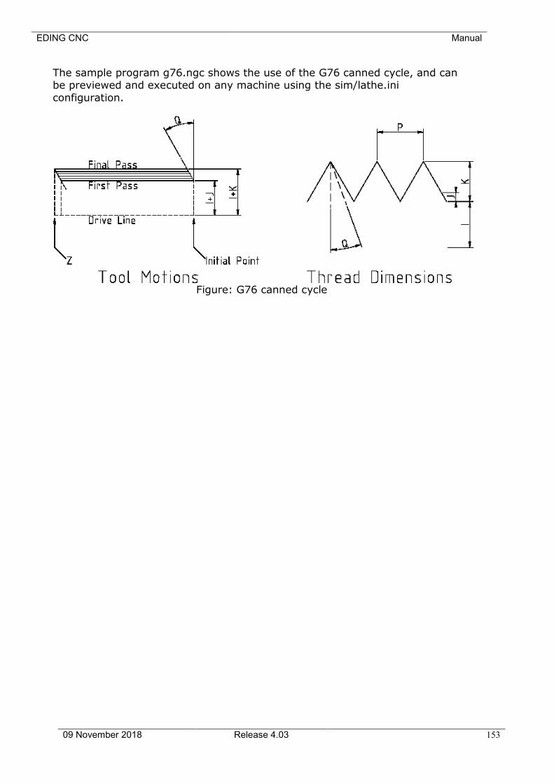
EDING CNC Manual
09 November 2018 Release 4.03 153
The sample program g76.ngc shows the use of the G76 canned cycle, and can be previewed and executed on any machine using the sim/lathe.ini
configuration.
Figure: G76 canned cycle
EDING CNC Manual
09 November 2018 Release 4.03 154
This is how it works: 1) Before the start, the spindle rate is measured.
2) The feed for de z-axis is calculated: F = pitch * spindleRate
3) The CPU programmed such that a movement is started on the spindle
pulse.
4) The movement is calculated and send to the CPU.
5) The movement is started when the spindle pulse passes.
6) Before the treading starts, the spindle-rate is measured, averaged and
the feed is calculated from this.
Not that the inside and outside thread diameter are determined by the start
position, the position before G76 and the I, K parameters.
3.6.19 Cancel Modal Motion - G80
Program G80 to ensure no axis motion will occur.
It is an error if: • Axis words are programmed when G80 is active, unless a modal group 0
G code is programmed which uses axis words.
3.6.20 Canned Cycles - G81 to G89
The canned cycles G81 through G89 have been implemented as described in this section. Two examples are given with the description of G81 below.
All canned cycles are performed with respect to the currently selected plane.
Any of the three planes (XY, YZ, and ZX) may be selected. Throughout this section, most of the descriptions assume the XY-plane has been selected. The behavior is always analogous if the YZ or XZ-plane is selected.
Rotational axis words are allowed in canned cycles, but it is better to omit them.
If rotational axis words are used, the numbers must be the same as the current position numbers so that the rotational axes do not move.
All canned cycles use X, Y, R, and Z numbers in the NC code. These numbers are used to determine X, Y, R, and Z positions. The R (usually meaning retract)
position is along the axis perpendicular to the currently selected plane (Z-axis for XY-plane, X-axis for YZ-plane, Y-axis for XZ-plane). Some canned cycles use
additional arguments. For canned cycles, we will call a number "sticky" if, when the same cycle is used
on several lines of code in a row, the number must be used the first time, but is optional on the rest of the lines. Sticky numbers keep their value on the rest of
the lines if they are not explicitly programmed to be different. The R number is always sticky.
EDING CNC Manual
09 November 2018 Release 4.03 155
In incremental distance mode: when the XY-plane is selected, X, Y, and R numbers are treated as increments to the current position and Z as an
increment from the Z-axis position before the move involving Z takes place; when the YZ or XZ-plane is selected, treatment of the axis words is analogous.
In absolute distance mode, the X, Y, R, and Z numbers are absolute positions in the current coordinate system.
The L number is optional and represents the number of repeats. L=0 is not allowed. If the repeat feature is used, it is normally used in incremental distance
mode, so that the same sequence of motions is repeated in several equally spaced places along a straight line. In absolute distance mode, L > 1 means "do the same cycle in the same place several times," Omitting the L word is
equivalent to specifying L=1. The L number is not sticky.
When L>1 in incremental mode with the XY-plane selected, the X and Y positions are determined by adding the given X and Y numbers either to the current X and Y positions (on the first go-around) or to the X and Y positions at
the end of the previous go-around (on the repetitions). The R and Z positions do not change during the repeats.
The height of the retract move at the end of each repeat (called "clear Z" in the
descriptions below) is determined by the setting of the retract mode: either to the original Z position (if that is above the R position and the retract mode is G98, OLD_Z), or otherwise to the R position. See Section 3.6.20
It is an error if:
• X, Y, and Z words are all missing during a canned cycle, • a P number is required and a negative P number is used, • an L number is used that does not evaluate to a positive integer,
• rotational axis motion is used during a canned cycle, • inverse time feed rate is active during a canned cycle,
• cutter radius compensation is active during a canned cycle. When the XY plane is active, the Z number is sticky, and it is an error if:
• the Z number is missing and the same canned cycle was not already active,
• the R number is less than the Z number. When the XZ plane is active, the Y number is sticky, and it is an error if:
• the Y number is missing and the same canned cycle was not already active,
• the R number is less than the Y number. When the YZ plane is active, the X number is sticky, and it is an error if:
• the X number is missing and the same canned cycle was not already active,
• the R number is less than the X number.
3.6.20.1 PRELIMINARY AND IN-BETWEEN MOTION
At the very beginning of the execution of any of the canned cycles, with the XY-plane
EDING CNC Manual
09 November 2018 Release 4.03 156
selected, if the current Z position is below the R position, the Z-axis is traversed to the R position. This happens only once, regardless of the value of L.
In addition, at the beginning of the first cycle and each repeat, the following one
or two moves are made: 1. a straight traverse parallel to the XY-plane to the given XY-position, 2. a straight traverse of the Z-axis only to the R position, if it is not already
at the R position.
If the XZ or YZ plane is active, the preliminary and in-between motions are analogous.
3.6.20.2 G81 CYCLE
The G81 cycle is intended for drilling. Program G81 X… Y… Z… A… B… C…
R… L… 1. Preliminary motion, as described above. 2. Move the Z-axis only at the current feed rate to the Z position.
3. Retract the Z-axis at traverse rate to clear Z.
Example: Suppose the current position is (1, 2, and 3) and the XY-plane has been selected, and the following line of NC code is interpreted.
G90 G81 G98 X4 Y5 Z1.5 R2.8
This calls for absolute distance mode (G90) and OLD_Z retract mode (G98) and calls for the G81 drilling cycle to be performed once. The X number and X
position are 4. The Y number and Y position are 5. The Z number and Z position are 1.5. The R number and clear Z are 2.8. Old Z is 3. The following moves take
place. 1. a traverse parallel to the XY-plane to (4,5,3) 2. a traverse parallel to the Z-axis to (4,5,2.8)
3. a feed parallel to the Z-axis to (4,5,1.5) 4. a traverse parallel to the Z-axis to (4,5,3)
Example: Suppose the current position is (1, 2, and 3) and the XY-plane has been selected, and the following line of NC code is interpreted.
G91 G81 G98 X4 Y5 Z-0.6 R1.8 L3
This calls for incremental distance mode (G91) and OLD_Z retract mode (G98)
and calls for the G81 drilling cycle to be repeated three times. The X number is 4, the Y number is 5, the Z number is -0.6 and the R number is 1.8. The initial X position is 5 (=1+4), the initial Y position is 7 (=2+5), the clear Z position is 4.8
(=1.8+3), and the Z position is 4.2 (=4.8-0.6). Old Z is 3. The first move is a traverse along the Z-axis to (1,2,4.8), since old Z < clear Z.
The first repeat consists of 3 moves. 1. a traverse parallel to the XY-plane to (5,7,4.8) 2. a feed parallel to the Z-axis to (5,7, 4.2)
3. a traverse parallel to the Z-axis to (5,7,4.8)
EDING CNC Manual
09 November 2018 Release 4.03 157
The second repeat consists of 3 moves. The X position is reset to 9 (=5+4) and the Y position to 12 (=7+5).
1. a traverse parallel to the XY-plane to (9,12,4.8) 2. a feed parallel to the Z-axis to (9,12, 4.2)
3. a traverse parallel to the Z-axis to (9,12,4.8) The third repeat consists of 3 moves. The X position is reset to 13 (=9+4) and
the Y position to 17 (=12+5). 1. a traverse parallel to the XY-plane to (13,17,4.8)
2. a feed parallel to the Z-axis to (13,17, 4.2) 3. a traverse parallel to the Z-axis to (13,17,4.8)
3.6.20.3 G82 CYCLE
The G82 cycle is intended for drilling. Program G82 X… Y… Z… A… R… L…
P… 1. Preliminary motion, as described above. 2. Move the Z-axis only at the current feed rate to the Z position.
3. Dwell for the P number of seconds. 4. Retract the Z-axis at traverse rate to clear Z.
3.6.20.4 G83 CYCLE
The G83 cycle (often called peck drilling) is intended for deep drilling or milling
with chip breaking. The retracts in this cycle clear the hole of chips and cut off any long stringers (which are common when drilling in aluminum). This cycle
takes a Q number which represents a "delta" increment along the Z-axis. Program G83 X… Y… Z… A… R… L… Q…
1. Preliminary motion, as described above.
2. Move the Z-axis only at the current feed rate downward by delta or to the Z position, whichever is less deep.
3. Rapid back out to the clear_z. 4. Rapid back down to the current hole bottom, backed off a bit. 5. Repeat steps 1, 2, and 3 until the Z position is reached at step 1.
6. Retract the Z-axis at traverse rate to clear Z.
It is an error if: • the Q number is negative or zero.
3.6.20.5 G73 CYCLE
The G73 cycle (often called peck drilling) is intended for deep drilling or milling with chip breaking. The retracts in this cycle clear the hole of chips and cut off
any long stringers (which are common when drilling in aluminum). This cycle takes a Q number which represents a "delta" increment along the Z-axis.
Program G73 X… Y… Z… A… R… L… Q… 1. Preliminary motion, as described above.
2. Move the Z-axis only at the current feed rate downward by delta or to the Z position, whichever is less deep.
3. Rapid back out but only with increment Q, this is the difference with G83
above. 4. Rapid back down to the current hole bottom, backed off a bit.
5. Repeat steps 1, 2, and 3 until the Z position is reached at step 1. 6. Retract the Z-axis at traverse rate to clear Z.
EDING CNC Manual
09 November 2018 Release 4.03 158
It is an error if:
• the Q number is negative or zero.
3.6.20.6 G84 CYCLE
The G84 cycle is intended for right hand tapping. Program G84 X… Y… Z… A… B… C… R… L…
1. Preliminary motion, as described above. 2. Move the Z-axis only at the current feed rate/per revolution to the Z
position. So assume the spindle is running M3 S600. Then and F value of F1 will give A feed of 600 /minute. Feed starts synchronized with spindle pulse
allowing to tap the same hole again. 3. When Z position reached, reverse spindle M4. (Waits until spindle ramp-
up and new measurement of spindle speed) 4. Retract the Z-axis at the current feed rate to clear Z.
3.6.20.7 G74 CYCLE
The G74 cycle is intended for left hand tapping. Program G74 X… Y… Z… A… B… C… R… L…
5. Preliminary motion, as described above. 6. Move the Z-axis only at the current feed rate/per revolution to the Z
position. So assume the spindle is running M3 S600. Then and F value of F1 will
give A feed of 600 /minute. Feed starts synchronized with spindle pulse allowing to tap the same hole again.
7. When Z position reached, reverse spindle M4. (Waits until spindle ramp-
up and new measurement of spindle speed) 8. Retract the Z-axis at the current feed rate to clear Z.
3.6.20.8 G85 CYCLE
The G85 cycle is intended for boring or reaming, but could be used for drilling or milling. Program G85 X… Y… Z… A… B… C… R… L…
Preliminary motion, as described above. Move the Z-axis only at the current feed rate to the Z position.
Retract the Z-axis at the current feed rate to clear Z.
3.6.20.9 G86 CYCLE
The G86 cycle is intended for boring. This cycle uses a P number for the number of seconds to dwell. Program G86 X… Y… Z… A… B… C… R… L… P…
Preliminary motion, as described above. Move the Z-axis only at the current feed rate to the Z position. Dwell for the P number of seconds.
Stop the spindle turning. Retract the Z-axis at traverse rate to clear Z.
Restart the spindle in the direction it was going. The spindle must be turning before this cycle is used. It is an error if:
the spindle is not turning before this cycle is executed.
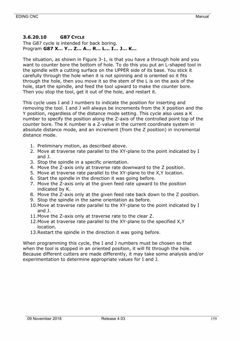
EDING CNC Manual
09 November 2018 Release 4.03 159
3.6.20.10 G87 CYCLE
The G87 cycle is intended for back boring. Program G87 X… Y… Z… A… R… L… I… J… K…
The situation, as shown in Figure 3-1, is that you have a through hole and you want to counter bore the bottom of hole. To do this you put an L-shaped tool in
the spindle with a cutting surface on the UPPER side of its base. You stick it carefully through the hole when it is not spinning and is oriented so it fits
through the hole, then you move it so the stem of the L is on the axis of the hole, start the spindle, and feed the tool upward to make the counter bore. Then you stop the tool, get it out of the hole, and restart it.
This cycle uses I and J numbers to indicate the position for inserting and
removing the tool. I and J will always be increments from the X position and the Y position, regardless of the distance mode setting. This cycle also uses a K number to specify the position along the Z-axis of the controlled point top of the
counter bore. The K number is a Z-value in the current coordinate system in absolute distance mode, and an increment (from the Z position) in incremental
distance mode.
1. Preliminary motion, as described above.
2. Move at traverse rate parallel to the XY-plane to the point indicated by I and J.
3. Stop the spindle in a specific orientation. 4. Move the Z-axis only at traverse rate downward to the Z position. 5. Move at traverse rate parallel to the XY-plane to the X,Y location.
6. Start the spindle in the direction it was going before. 7. Move the Z-axis only at the given feed rate upward to the position
indicated by K. 8. Move the Z-axis only at the given feed rate back down to the Z position. 9. Stop the spindle in the same orientation as before.
10.Move at traverse rate parallel to the XY-plane to the point indicated by I and J.
11.Move the Z-axis only at traverse rate to the clear Z. 12.Move at traverse rate parallel to the XY-plane to the specified X,Y
location.
13.Restart the spindle in the direction it was going before.
When programming this cycle, the I and J numbers must be chosen so that when the tool is stopped in an oriented position, it will fit through the hole.
Because different cutters are made differently, it may take some analysis and/or experimentation to determine appropriate values for I and J.
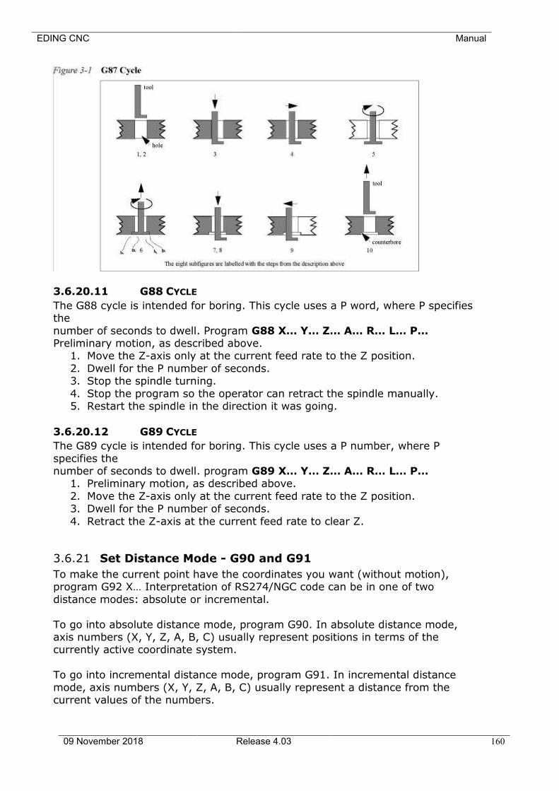
EDING CNC Manual
09 November 2018 Release 4.03 160
3.6.20.11 G88 CYCLE
The G88 cycle is intended for boring. This cycle uses a P word, where P specifies the
number of seconds to dwell. Program G88 X… Y… Z… A… R… L… P… Preliminary motion, as described above.
1. Move the Z-axis only at the current feed rate to the Z position.
2. Dwell for the P number of seconds. 3. Stop the spindle turning.
4. Stop the program so the operator can retract the spindle manually. 5. Restart the spindle in the direction it was going.
3.6.20.12 G89 CYCLE
The G89 cycle is intended for boring. This cycle uses a P number, where P
specifies the number of seconds to dwell. program G89 X… Y… Z… A… R… L… P…
1. Preliminary motion, as described above.
2. Move the Z-axis only at the current feed rate to the Z position. 3. Dwell for the P number of seconds.
4. Retract the Z-axis at the current feed rate to clear Z.
3.6.21 Set Distance Mode - G90 and G91
To make the current point have the coordinates you want (without motion), program G92 X… Interpretation of RS274/NGC code can be in one of two
distance modes: absolute or incremental.
To go into absolute distance mode, program G90. In absolute distance mode, axis numbers (X, Y, Z, A, B, C) usually represent positions in terms of the currently active coordinate system.
To go into incremental distance mode, program G91. In incremental distance
mode, axis numbers (X, Y, Z, A, B, C) usually represent a distance from the current values of the numbers.
EDING CNC Manual
09 November 2018 Release 4.03 161
I and J numbers always represent increments, regardless of the distance mode
3.6.22 Coordinate System Offsets - G92, G92.1, G92.2, G92.3
To make the current point have the coordinates you want (without motion), program
G92 X… Y… Z… A… , where the axis words contain the axis numbers you want. All axis words are optional, except that at least one must be used. If an
axis word is not used for a given axis, the coordinate on that axis of the current point is not changed.
It is an error if: • all axis words are omitted.
When G92 is executed, the origin of the currently active coordinate system moves. To do this, origin offsets are calculated so that the coordinates of the
current point with respect to the moved origin are as specified on the line containing the G92. In addition, parameters 5211 to 5216 are set to the X, Y, Z,
A, B, and C-axis offsets. The offset for an axis is the amount the origin must be moved so that the coordinate of the controlled point on the axis has the specified value.
Here is an example. Suppose the current point is at X=4 in the currently
specified coordinate system and the current X-axis offset is zero, then G92 x7 sets the X-axis offset to -3, sets parameter 5211 to -3, and causes the X-coordinate of the current point to be 7.
The axis offsets are always used when motion is specified in absolute distance
mode using any of the nine coordinate systems (those designated by G54 - G59.3). Thus all nine coordinate systems are affected by G92.
Being in incremental distance mode has no effect on the action of G92.
Non-zero offsets may already be in effect when the G92 is called. If this is the case, the new value of each offset is A+B, where A is what the offset would be if
the old offset were zero, and B is the old offset. For example, after the previous example, the X-value of the current point is 7. If G92 x9 is then programmed, the new X-axis offset is -5, which is calculated by [[7-9] + -3].
To reset axis offsets to zero, program G92.1 or G92.2. G92.1 sets parameters
5211 to 5216 to zero, whereas G92.2 leaves their current values alone. To set the axis offset values to the values given in parameters 5211 to 5216, program G92.3.
You can set axis offsets in one program and use the same offsets in another
program. Program G92 in the first program. This will set parameters 5211 to 5216. Do not use G92.1 in the remainder of the first program. The parameter values will be saved when the first program exits and restored when the second
one starts up. Use G92.3 near the beginning of the second program. That will restore the offsets saved in the first program. If other programs are to run
between the program that sets the offsets and the one that restores them,
EDING CNC Manual
09 November 2018 Release 4.03 162
make a copy of the parameter file written by the first program and use it as the parameter file for the second program.
3.6.23 Set Feed Rate Mode - G93, G94, G95
Three feed rate modes are recognized, depending on selected mode the Feed of the axes is calculated differently:
• G93 inverse time, a move is completed in 1/F minutes. For example if F=6 the move is completed in 10 seconds. When G93 is active, the F must be specified on every line containing G1,G3 or G3.
• G94 units per minute, this is the normal mode for milling, F means units per minute, in millimeter mode mm/minute, in INCH mode inch/minute.
• G95 Units per revolution, here the F word is the number of units that should be cut per spindle revolution. So the feed of the axes is depending on the rotation speed of the spindle. G95 F2 means cut 2mm every spindle
revolution, so when S=500, the feed for XZ would be FEED = F * S = 2 * 500 = 1000.
3.6.24 Spindle Control Mode – G96, G97
Two spindle control modes are possible, depending on the mode the spindle speed is calculated differently:
• G96 (Only for Lathe), select constant surface speed, S is now specified as meters per minute in mm mode (G21) or Feet per minute in inch mode
(G20). This means that the spindle speed is adapted automatically when the Radius changes. Suppose you program G96 S150 in millimeter mode, the spindle speed is calculated by: RPM = S / (2 * PI * X), X is the radius. So
your X zero must be where the diameter is zero. Example: Your actual X position is 100 (100 millimeter = 0.1 meter), you
program G96 S150 D1000, this would result in a spindle RPM of 150 / (2 * PI * 0.1) = 238.7 rev/min. D1000 limits the maximum speed to 1000 RPM.
• G97 is normal RPM mode, S specifies the RPM.
3.6.25 Set Canned Cycle Return Level - G98 and G99
When the spindle retracts during canned cycles, there is a choice of how far it retracts:
(1) retract perpendicular to the selected plane to the position indicated by the R word, or (2) retract perpendicular to the selected plane to the position that axis was in
just before the canned cycle started (unless that position is lower than the position indicated by the R word, in which case use the R word position).
To use option (1), program G99. To use option (2), program G98. Remember that the R word has different meanings in absolute distance mode and
incremental distance mode.
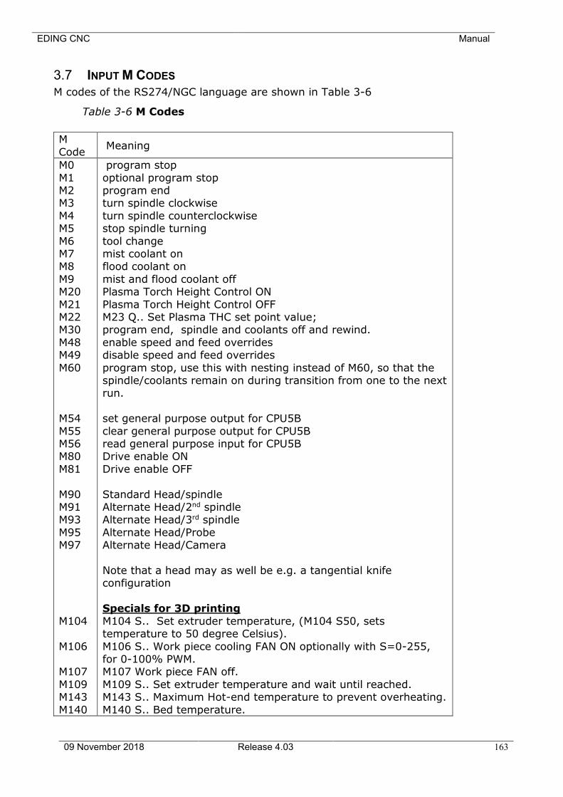
EDING CNC Manual
09 November 2018 Release 4.03 163
3.7 INPUT M CODES
M codes of the RS274/NGC language are shown in Table 3-6
Table 3-6 M Codes
M
Code Meaning
M0
M1 M2 M3
M4 M5
M6 M7 M8
M9 M20
M21 M22 M30
M48 M49
M60
M54
M55 M56 M80
M81
M90 M91 M93
M95 M97
M104
M106 M107
M109 M143
M140
program stop
optional program stop program end turn spindle clockwise
turn spindle counterclockwise stop spindle turning
tool change mist coolant on flood coolant on
mist and flood coolant off Plasma Torch Height Control ON
Plasma Torch Height Control OFF M23 Q.. Set Plasma THC set point value; program end, spindle and coolants off and rewind.
enable speed and feed overrides disable speed and feed overrides
program stop, use this with nesting instead of M60, so that the spindle/coolants remain on during transition from one to the next run.
set general purpose output for CPU5B
clear general purpose output for CPU5B read general purpose input for CPU5B Drive enable ON
Drive enable OFF
Standard Head/spindle Alternate Head/2nd spindle Alternate Head/3rd spindle
Alternate Head/Probe Alternate Head/Camera
Note that a head may as well be e.g. a tangential knife configuration
Specials for 3D printing
M104 S.. Set extruder temperature, (M104 S50, sets temperature to 50 degree Celsius).
M106 S.. Work piece cooling FAN ON optionally with S=0-255, for 0-100% PWM. M107 Work piece FAN off.
M109 S.. Set extruder temperature and wait until reached. M143 S.. Maximum Hot-end temperature to prevent overheating.
M140 S.. Bed temperature.
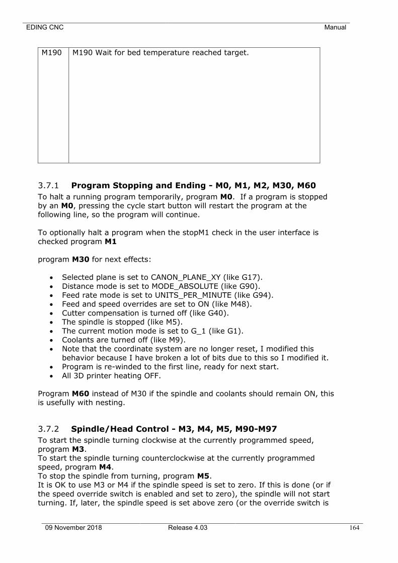
EDING CNC Manual
09 November 2018 Release 4.03 164
M190 M190 Wait for bed temperature reached target.
3.7.1 Program Stopping and Ending - M0, M1, M2, M30, M60
To halt a running program temporarily, program M0. If a program is stopped by an M0, pressing the cycle start button will restart the program at the following line, so the program will continue.
To optionally halt a program when the stopM1 check in the user interface is
checked program M1 program M30 for next effects:
• Selected plane is set to CANON_PLANE_XY (like G17).
• Distance mode is set to MODE_ABSOLUTE (like G90). • Feed rate mode is set to UNITS_PER_MINUTE (like G94). • Feed and speed overrides are set to ON (like M48).
• Cutter compensation is turned off (like G40). • The spindle is stopped (like M5).
• The current motion mode is set to G_1 (like G1). • Coolants are turned off (like M9). • Note that the coordinate system are no longer reset, I modified this
behavior because I have broken a lot of bits due to this so I modified it. • Program is re-winded to the first line, ready for next start.
• All 3D printer heating OFF.
Program M60 instead of M30 if the spindle and coolants should remain ON, this is usefully with nesting.
3.7.2 Spindle/Head Control - M3, M4, M5, M90-M97
To start the spindle turning clockwise at the currently programmed speed,
program M3. To start the spindle turning counterclockwise at the currently programmed speed, program M4.
To stop the spindle from turning, program M5. It is OK to use M3 or M4 if the spindle speed is set to zero. If this is done (or if
the speed override switch is enabled and set to zero), the spindle will not start turning. If, later, the spindle speed is set above zero (or the override switch is
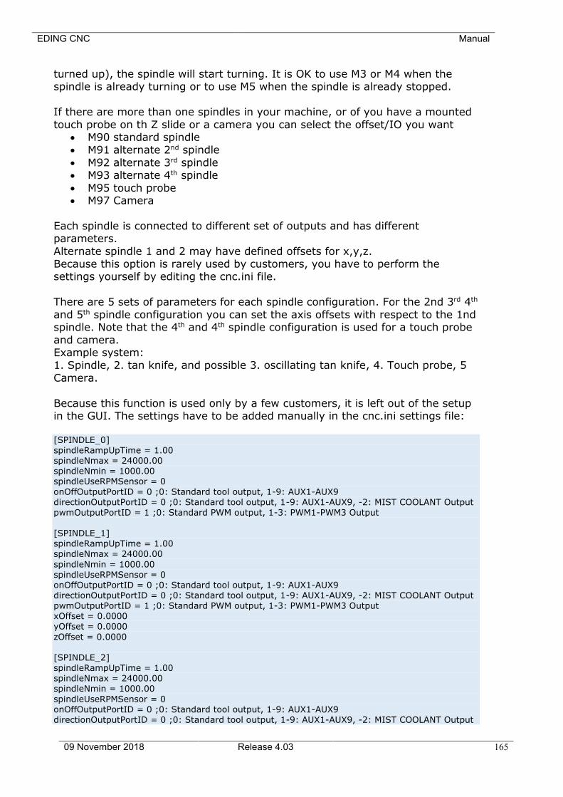
EDING CNC Manual
09 November 2018 Release 4.03 165
turned up), the spindle will start turning. It is OK to use M3 or M4 when the spindle is already turning or to use M5 when the spindle is already stopped.
If there are more than one spindles in your machine, or of you have a mounted
touch probe on th Z slide or a camera you can select the offset/IO you want • M90 standard spindle • M91 alternate 2nd spindle
• M92 alternate 3rd spindle • M93 alternate 4th spindle
• M95 touch probe • M97 Camera
Each spindle is connected to different set of outputs and has different parameters.
Alternate spindle 1 and 2 may have defined offsets for x,y,z. Because this option is rarely used by customers, you have to perform the settings yourself by editing the cnc.ini file.
There are 5 sets of parameters for each spindle configuration. For the 2nd 3rd 4th
and 5th spindle configuration you can set the axis offsets with respect to the 1nd spindle. Note that the 4th and 4th spindle configuration is used for a touch probe
and camera. Example system: 1. Spindle, 2. tan knife, and possible 3. oscillating tan knife, 4. Touch probe, 5
Camera.
Because this function is used only by a few customers, it is left out of the setup in the GUI. The settings have to be added manually in the cnc.ini settings file: [SPINDLE_0] spindleRampUpTime = 1.00 spindleNmax = 24000.00 spindleNmin = 1000.00 spindleUseRPMSensor = 0
onOffOutputPortID = 0 ;0: Standard tool output, 1-9: AUX1-AUX9 directionOutputPortID = 0 ;0: Standard tool output, 1-9: AUX1-AUX9, -2: MIST COOLANT Output
pwmOutputPortID = 1 ;0: Standard PWM output, 1-3: PWM1-PWM3 Output [SPINDLE_1] spindleRampUpTime = 1.00 spindleNmax = 24000.00
spindleNmin = 1000.00 spindleUseRPMSensor = 0 onOffOutputPortID = 0 ;0: Standard tool output, 1-9: AUX1-AUX9 directionOutputPortID = 0 ;0: Standard tool output, 1-9: AUX1-AUX9, -2: MIST COOLANT Output pwmOutputPortID = 1 ;0: Standard PWM output, 1-3: PWM1-PWM3 Output xOffset = 0.0000 yOffset = 0.0000
zOffset = 0.0000 [SPINDLE_2]
spindleRampUpTime = 1.00 spindleNmax = 24000.00 spindleNmin = 1000.00
spindleUseRPMSensor = 0 onOffOutputPortID = 0 ;0: Standard tool output, 1-9: AUX1-AUX9 directionOutputPortID = 0 ;0: Standard tool output, 1-9: AUX1-AUX9, -2: MIST COOLANT Output
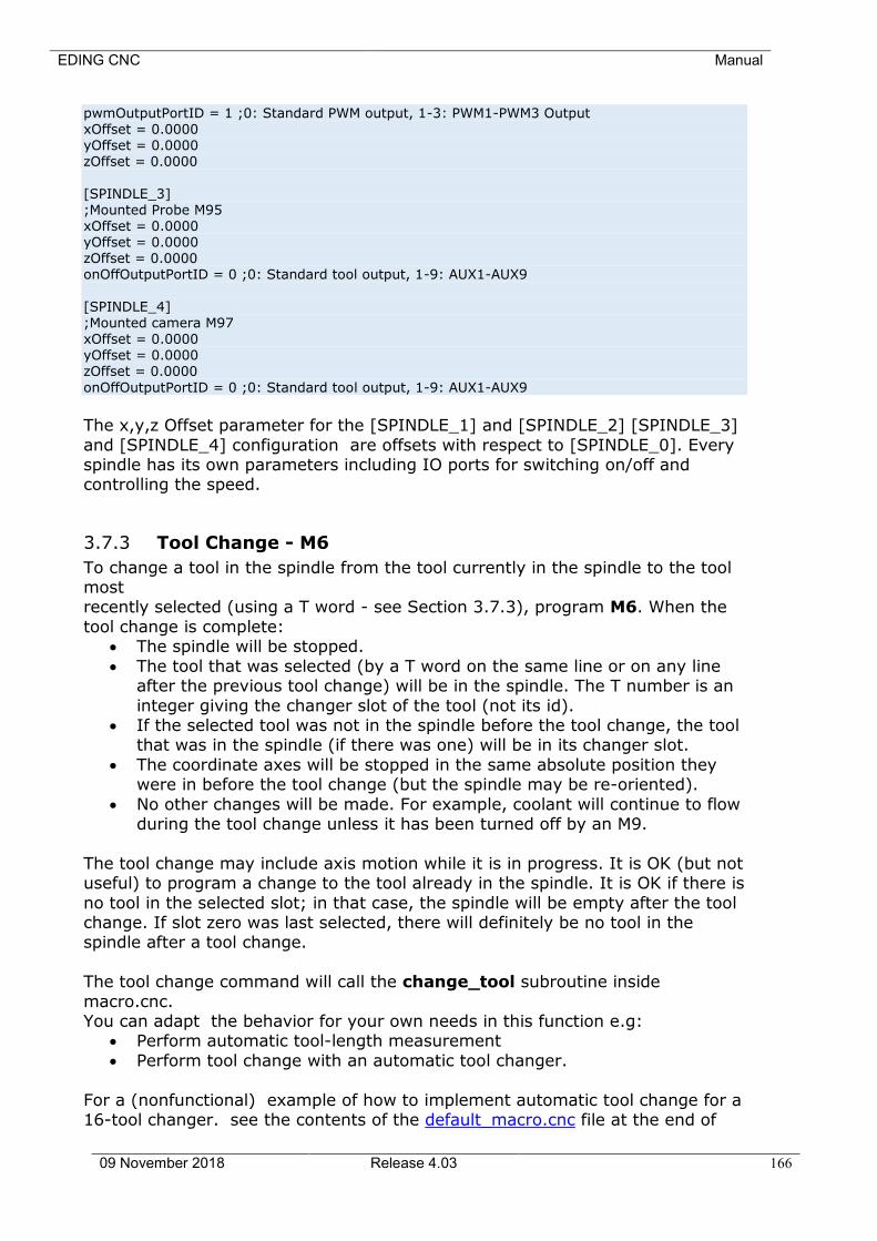
EDING CNC Manual
09 November 2018 Release 4.03 166
pwmOutputPortID = 1 ;0: Standard PWM output, 1-3: PWM1-PWM3 Output xOffset = 0.0000 yOffset = 0.0000 zOffset = 0.0000
[SPINDLE_3] ;Mounted Probe M95 xOffset = 0.0000 yOffset = 0.0000 zOffset = 0.0000 onOffOutputPortID = 0 ;0: Standard tool output, 1-9: AUX1-AUX9
[SPINDLE_4] ;Mounted camera M97
xOffset = 0.0000 yOffset = 0.0000 zOffset = 0.0000
onOffOutputPortID = 0 ;0: Standard tool output, 1-9: AUX1-AUX9
The x,y,z Offset parameter for the [SPINDLE_1] and [SPINDLE_2] [SPINDLE_3]
and [SPINDLE_4] configuration are offsets with respect to [SPINDLE_0]. Every spindle has its own parameters including IO ports for switching on/off and controlling the speed.
3.7.3 Tool Change - M6
To change a tool in the spindle from the tool currently in the spindle to the tool most recently selected (using a T word - see Section 3.7.3), program M6. When the
tool change is complete: • The spindle will be stopped.
• The tool that was selected (by a T word on the same line or on any line after the previous tool change) will be in the spindle. The T number is an
integer giving the changer slot of the tool (not its id). • If the selected tool was not in the spindle before the tool change, the tool
that was in the spindle (if there was one) will be in its changer slot.
• The coordinate axes will be stopped in the same absolute position they were in before the tool change (but the spindle may be re-oriented).
• No other changes will be made. For example, coolant will continue to flow during the tool change unless it has been turned off by an M9.
The tool change may include axis motion while it is in progress. It is OK (but not useful) to program a change to the tool already in the spindle. It is OK if there is
no tool in the selected slot; in that case, the spindle will be empty after the tool change. If slot zero was last selected, there will definitely be no tool in the spindle after a tool change.
The tool change command will call the change_tool subroutine inside
macro.cnc. You can adapt the behavior for your own needs in this function e.g:
• Perform automatic tool-length measurement
• Perform tool change with an automatic tool changer.
For a (nonfunctional) example of how to implement automatic tool change for a 16-tool changer. see the contents of the default_macro.cnc file at the end of
EDING CNC Manual
09 November 2018 Release 4.03 167
this document. It checks whether current tool is already in the spindle. It check that the tool number is in range of 1-4. Then it first drops current tool and picks
the new tool:
3.7.4 Coolant Control - M7, M8, M9
To turn mist coolant on, program M7. To turn flood coolant on, program M8. To
turn all coolant off, program M9. It is always OK to use any of these commands, regardless of what coolant is on or off.
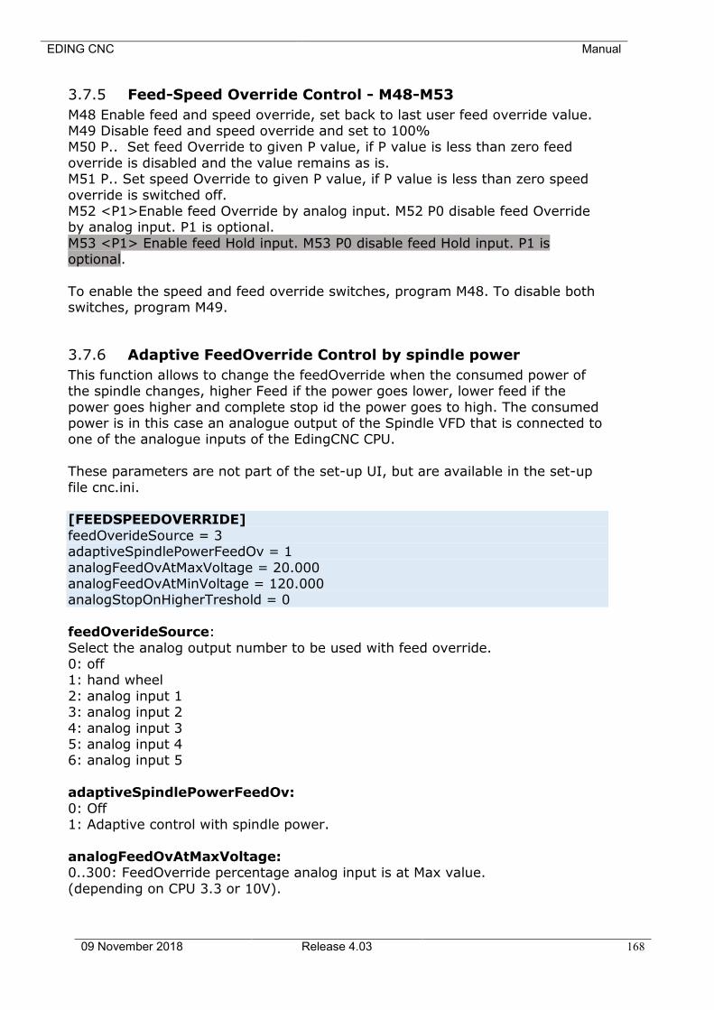
EDING CNC Manual
09 November 2018 Release 4.03 168
3.7.5 Feed-Speed Override Control - M48-M53
M48 Enable feed and speed override, set back to last user feed override value. M49 Disable feed and speed override and set to 100% M50 P.. Set feed Override to given P value, if P value is less than zero feed
override is disabled and the value remains as is. M51 P.. Set speed Override to given P value, if P value is less than zero speed
override is switched off. M52 <P1>Enable feed Override by analog input. M52 P0 disable feed Override by analog input. P1 is optional.
M53 <P1> Enable feed Hold input. M53 P0 disable feed Hold input. P1 is optional.
To enable the speed and feed override switches, program M48. To disable both switches, program M49.
3.7.6 Adaptive FeedOverride Control by spindle power
This function allows to change the feedOverride when the consumed power of the spindle changes, higher Feed if the power goes lower, lower feed if the
power goes higher and complete stop id the power goes to high. The consumed power is in this case an analogue output of the Spindle VFD that is connected to one of the analogue inputs of the EdingCNC CPU.
These parameters are not part of the set-up UI, but are available in the set-up
file cnc.ini. [FEEDSPEEDOVERRIDE]
feedOverideSource = 3 adaptiveSpindlePowerFeedOv = 1
analogFeedOvAtMaxVoltage = 20.000 analogFeedOvAtMinVoltage = 120.000 analogStopOnHigherTreshold = 0
feedOverideSource:
Select the analog output number to be used with feed override. 0: off 1: hand wheel
2: analog input 1 3: analog input 2
4: analog input 3 5: analog input 4 6: analog input 5
adaptiveSpindlePowerFeedOv:
0: Off 1: Adaptive control with spindle power.
analogFeedOvAtMaxVoltage: 0..300: FeedOverride percentage analog input is at Max value.
(depending on CPU 3.3 or 10V).
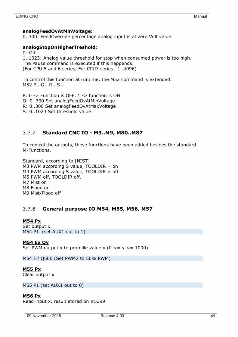
EDING CNC Manual
09 November 2018 Release 4.03 169
analogFeedOvAtMinVoltage: 0..300: FeedOverride percentage analog input is at zero Volt value.
analogStopOnHigherTreshold:
0: Off 1..1023: Analog value threshold for stop when consumed power is too high. The Pause command is executed if this happends.
(For CPU 5 and 6 series, For CPU7 series `1..4096)
To control this function at runtime, the M52 command is extended: M52 P.. Q.. R.. S..
P: 0 -> Function is OFF, 1 -> function is ON. Q: 0..300 Set analogFeedOvAtMinVoltage
R: 0..300 Set analogFeedOvAtMaxVoltage S: 0..1023 Set threshold value.
3.7.7 Standard CNC IO - M3..M9, M80..M87
To control the outputs, these functions have been added besides the standard
M-Functions. Standard, according to [NIST]
M3 PWM according S value, TOOLDIR = on M4 PWM according S value, TOOLDIR = off
M5 PWM off, TOOLDIR off. M7 Mist on M8 Flood on
M9 Mist/Flood off
3.7.8 General purpose IO M54, M55, M56, M57
M54 Px Set output x. M54 P1 (set AUX1 out to 1)
M54 Ex Qy
Set PWM output x to promille value y (0 <= y <= 1000) M54 E2 Q500 (Set PWM2 to 50% PWM)
M55 Px
Clear output x.
M55 P1 (set AUX1 out to 0) M56 Px
Read input x. result stored on #5399
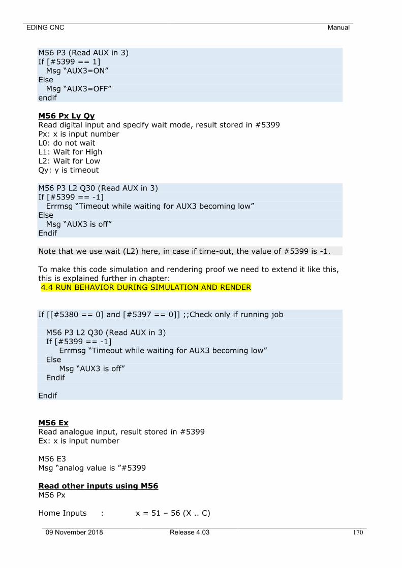
EDING CNC Manual
09 November 2018 Release 4.03 170
M56 P3 (Read AUX in 3) If [#5399 == 1]
Msg “AUX3=ON” Else
Msg “AUX3=OFF” endif
M56 Px Ly Qy Read digital input and specify wait mode, result stored in #5399
Px: x is input number L0: do not wait L1: Wait for High
L2: Wait for Low Qy: y is timeout
M56 P3 L2 Q30 (Read AUX in 3) If [#5399 == -1]
Errmsg “Timeout while waiting for AUX3 becoming low” Else
Msg “AUX3 is off” Endif
Note that we use wait (L2) here, in case if time-out, the value of #5399 is -1.
To make this code simulation and rendering proof we need to extend it like this, this is explained further in chapter:
4.4 RUN BEHAVIOR DURING SIMULATION AND RENDER
If [[#5380 == 0] and [#5397 == 0]] ;;Check only if running job
M56 P3 L2 Q30 (Read AUX in 3) If [#5399 == -1] Errmsg “Timeout while waiting for AUX3 becoming low”
Else Msg “AUX3 is off”
Endif Endif
M56 Ex Read analogue input, result stored in #5399 Ex: x is input number
M56 E3
Msg “analog value is ”#5399 Read other inputs using M56
M56 Px
Home Inputs : x = 51 – 56 (X .. C)
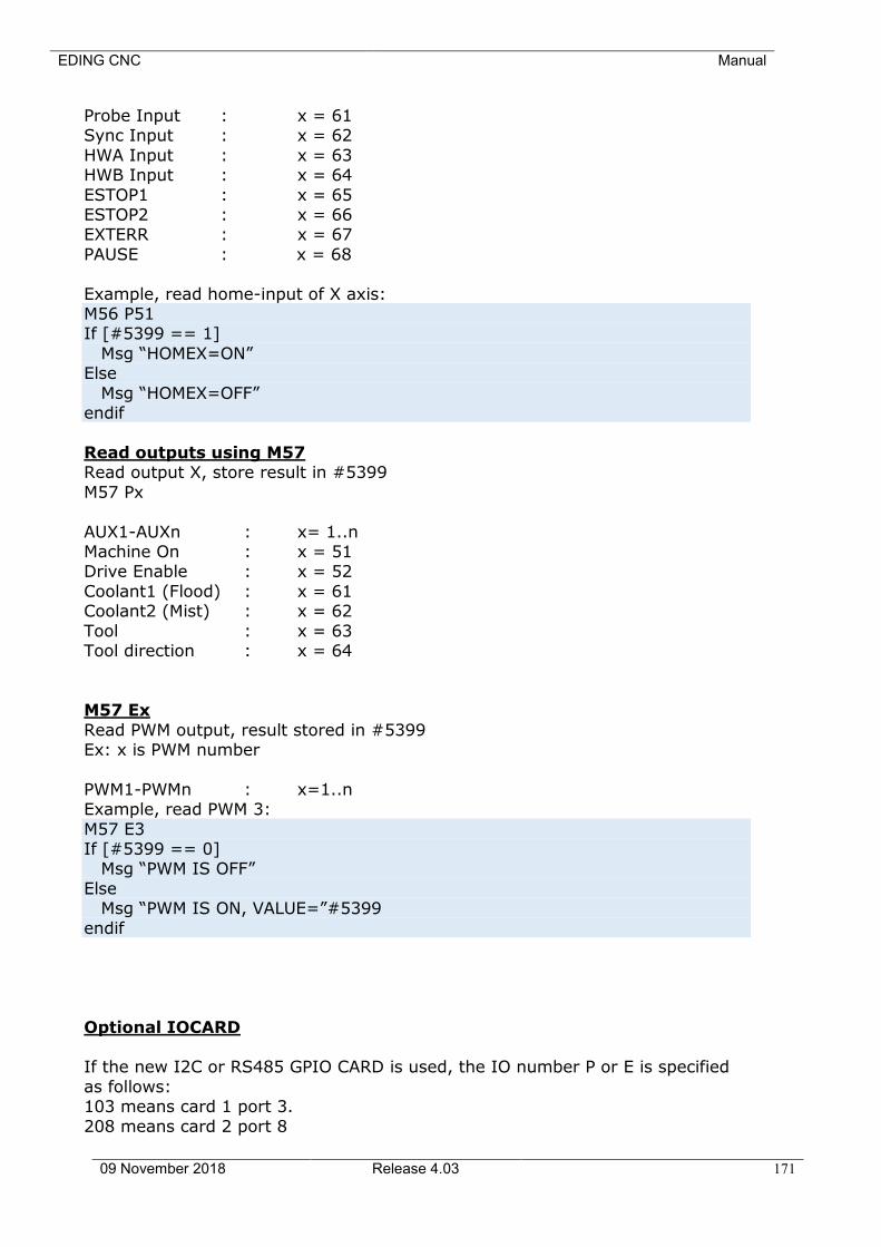
EDING CNC Manual
09 November 2018 Release 4.03 171
Probe Input : x = 61 Sync Input : x = 62
HWA Input : x = 63 HWB Input : x = 64
ESTOP1 : x = 65 ESTOP2 : x = 66 EXTERR : x = 67
PAUSE : x = 68
Example, read home-input of X axis: M56 P51 If [#5399 == 1]
Msg “HOMEX=ON” Else
Msg “HOMEX=OFF” endif
Read outputs using M57 Read output X, store result in #5399
M57 Px
AUX1-AUXn : x= 1..n Machine On : x = 51 Drive Enable : x = 52
Coolant1 (Flood) : x = 61 Coolant2 (Mist) : x = 62
Tool : x = 63 Tool direction : x = 64
M57 Ex
Read PWM output, result stored in #5399 Ex: x is PWM number
PWM1-PWMn : x=1..n Example, read PWM 3:
M57 E3 If [#5399 == 0] Msg “PWM IS OFF”
Else Msg “PWM IS ON, VALUE=”#5399
endif
Optional IOCARD If the new I2C or RS485 GPIO CARD is used, the IO number P or E is specified
as follows: 103 means card 1 port 3.
208 means card 2 port 8
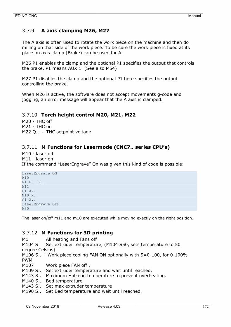
EDING CNC Manual
09 November 2018 Release 4.03 172
3.7.9 A axis clamping M26, M27
The A axis is often used to rotate the work piece on the machine and then do milling on that side of the work piece. To be sure the work piece is fixed at its
place an axis clamp (Brake) can be used for A.
M26 P1 enables the clamp and the optional P1 specifies the output that controls the brake, P1 means AUX 1. (See also M54)
M27 P1 disables the clamp and the optional P1 here specifies the output controlling the brake.
When M26 is active, the software does not accept movements g-code and jogging, an error message will appear that the A axis is clamped.
3.7.10 Torch height control M20, M21, M22
M20 - THC off M21 - THC on
M22 Q.. – THC setpoint voltage
3.7.11 M Functions for Lasermode (CNC7.. series CPU’s)
M10 - laser off M11 - laser on
If the command “LaserEngrave” On was given this kind of code is possible: LaserEngrave ON
M10
G1 F.. X..
M11
G1 X..
M10 X..
G1 X..
LaserEngrave OFF
M30
The laser on/off m11 and m10 are executed while moving exactly on the right position.
3.7.12 M Functions for 3D printing
M1 :All heating and Fans off
M104 S :Set extruder temperature, (M104 S50, sets temperature to 50 degree Celsius).
M106 S.. : Work piece cooling FAN ON optionally with S=0-100, for 0-100% PWM M107 :Work piece FAN off .
M109 S.. :Set extruder temperature and wait until reached. M143 S.. :Maximum Hot-end temperature to prevent overheating.
M140 S.. :Bed temperature M143 S.. :Set max extruder temperature M190 S.. :Set Bed temperature and wait until reached.
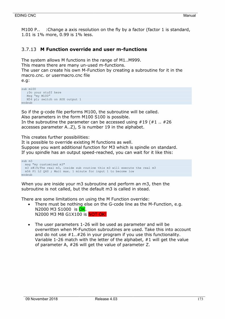
EDING CNC Manual
09 November 2018 Release 4.03 173
M100 P.. :Change a axis resolution on the fly by a factor (factor 1 is standard, 1.01 is 1% more, 0.99 is 1% less.
3.7.13 M Function override and user m-functions
The system allows M functions in the range of M1..M999. This means there are many un-used m-functions. The user can create his own M-Function by creating a subroutine for it in the
macro.cnc. or usermacro.cnc file e.g: sub m100
;Do your stuff here
Msg “my M100”
M54 p1; switch on AUX output 1
endsub
So if the g-code file performs M100, the subroutine will be called. Also parameters in the form M100 S100 is possible.
In the subroutine the parameter can be accessed using #19 (#1 .. #26 accesses parameter A..Z), S is number 19 in the alphabet.
This creates further possibilities: It is possible to override existing M functions as well.
Suppose you want additional function for M3 which is spindle on standard. If you spindle has an output speed-reached, you can wait for it like this: sub m3
msg "my customized m3"
m3 s#19;The real m3, inside sub routine this m3 will execute the real m3
m56 P1 L2 Q60 ; Wait max. 1 minute for input 1 to become low
endsub
When you are inside your m3 subroutine and perform an m3, then the subroutine is not called, but the default m3 is called in stead.
There are some limitations on using the M Function override: • There must be nothing else on the G-code line as the M-Function, e.g.
N2000 M3 S1000 is OK. N2000 M3 M8 G1X100 is NOT OK!
• The user parameters 1-26 will be used as parameter and will be overwritten when M-Function subroutines are used. Take this into account
and do not use #1..#26 in your program if you use this functionality. Variable 1-26 match with the letter of the alphabet, #1 will get the value of parameter A, #26 will get the value of parameter Z.

EDING CNC Manual
09 November 2018 Release 4.03 174
3.8 OTHER INPUT CODES
3.8.1 Set Feed Rate - F
To set the feed rate, program F… . The application of the feed rate is as described in Section 2.1.2.5, unless inverse time feed rate mode is in effect, in which case
the feed rate is as described in Section 3.6.23.
3.8.2 Set Spindle Speed - S
To set the speed in revolutions per minute (rpm) of the spindle, program S… .
The spindle will turn at that speed when it has been programmed to start turning. It is OK to program an S word whether the spindle is turning or not. If the speed override switch is
enabled and not set at 100%, the speed will be different from what is programmed. It is OK to program S0; the spindle will not turn if that is done.
The CPU’s that support PWM output will have its PWM value set conform the requested spindle speed if the spindle is turned on.
It is an error if: • the S number is negative.
3.8.3 Select Tool - T
To select a tool, program T…, where the T number is the carousel slot for the tool. The tool is not changed until an M6 is programmed (see Section 3.7.3). The T word may appear on the same line as the M6 or on a previous line. It is
OK, but not normally useful, if T words appear on two or more lines with no tool change. The carousel may move a lot, but only the most recent T word will take
effect at the next tool change. It is OK to program T0; no tool will be selected. This is useful if you want the spindle to be empty after a tool change.
It is an error if:
• a negative T number is used, • a T number larger than the number of slots in the carousel is used.
On some machines, the carousel will move when a T word is programmed, at the same time machining is occurring. On such machines, programming the T
word several lines before a tool change will save time. A common programming practice for such machines is to put the T word for the next tool to be used on
the line after a tool change. This maximizes the time available for the carousel to move.
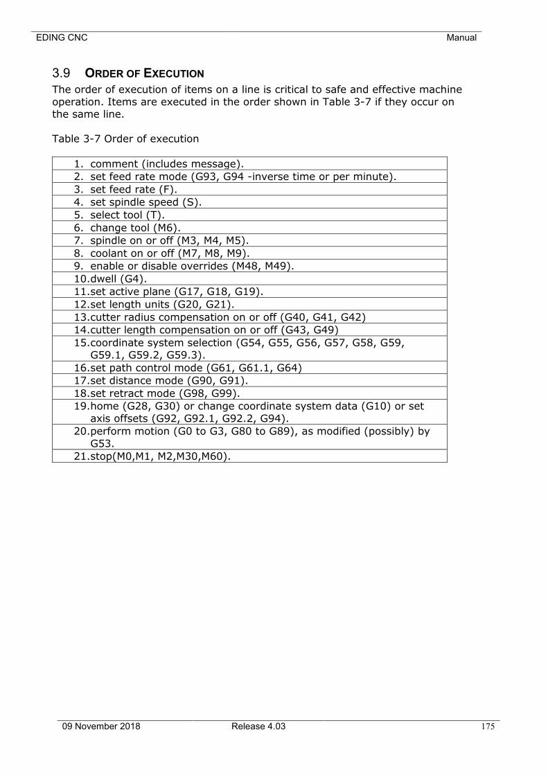
EDING CNC Manual
09 November 2018 Release 4.03 175
3.9 ORDER OF EXECUTION
The order of execution of items on a line is critical to safe and effective machine
operation. Items are executed in the order shown in Table 3-7 if they occur on the same line.
Table 3-7 Order of execution
1. comment (includes message).
2. set feed rate mode (G93, G94 -inverse time or per minute).
3. set feed rate (F).
4. set spindle speed (S).
5. select tool (T).
6. change tool (M6).
7. spindle on or off (M3, M4, M5).
8. coolant on or off (M7, M8, M9).
9. enable or disable overrides (M48, M49).
10.dwell (G4).
11.set active plane (G17, G18, G19).
12.set length units (G20, G21).
13.cutter radius compensation on or off (G40, G41, G42)
14.cutter length compensation on or off (G43, G49)
15.coordinate system selection (G54, G55, G56, G57, G58, G59, G59.1, G59.2, G59.3).
16.set path control mode (G61, G61.1, G64)
17.set distance mode (G90, G91).
18.set retract mode (G98, G99).
19.home (G28, G30) or change coordinate system data (G10) or set
axis offsets (G92, G92.1, G92.2, G94).
20.perform motion (G0 to G3, G80 to G89), as modified (possibly) by
G53.
21.stop(M0,M1, M2,M30,M60).

EDING CNC Manual
09 November 2018 Release 4.03 176
4 Language extensions
To provide additional flexibility, EdingCNC created some extensions in the language that allow for flexible programming.
EDING CNC Manual
09 November 2018 Release 4.03 177
4.1 FLOW CONTROL
You can use the following flow control commands in a job:
IF[x]-ELSE-ENDIF constructs to define x dependent execution WHILE[x]-ENDWHILE constructs to define x dependent repeated execution SUB <name>-ENDSUB constructs to define a subroutine
GOSUB <name> construct to call a subroutine

EDING CNC Manual
09 November 2018 Release 4.03 178
4.2 SUPPORTED OPERATIONS ON EXPRESSIONS
4.2.1 unary operations
abs absolute value acos arc cosine
asin arc sine atan[y]/[x] arc tangent
cos cosine exp e raised to
fix round down fup round int integer part
ln natural log of round round
sin sine sqrt square root tan tangent
not logical not ResetModulo [A|B|C] reset a rotation axis to its modulo position.
4.2.2 binary operations:
/ divided by mod modulo ** power
* times and logic and
xor logic exclusive or - minus or logic nonexclusive or
+ plus > greater then
>= greater than or equal < less then <= less than or equal
== is equal <> not equal
band bitwise and bxor bitwise exclusive or bor bitwise nonexclusive or
<< shift left >> shift right
Some examples below.
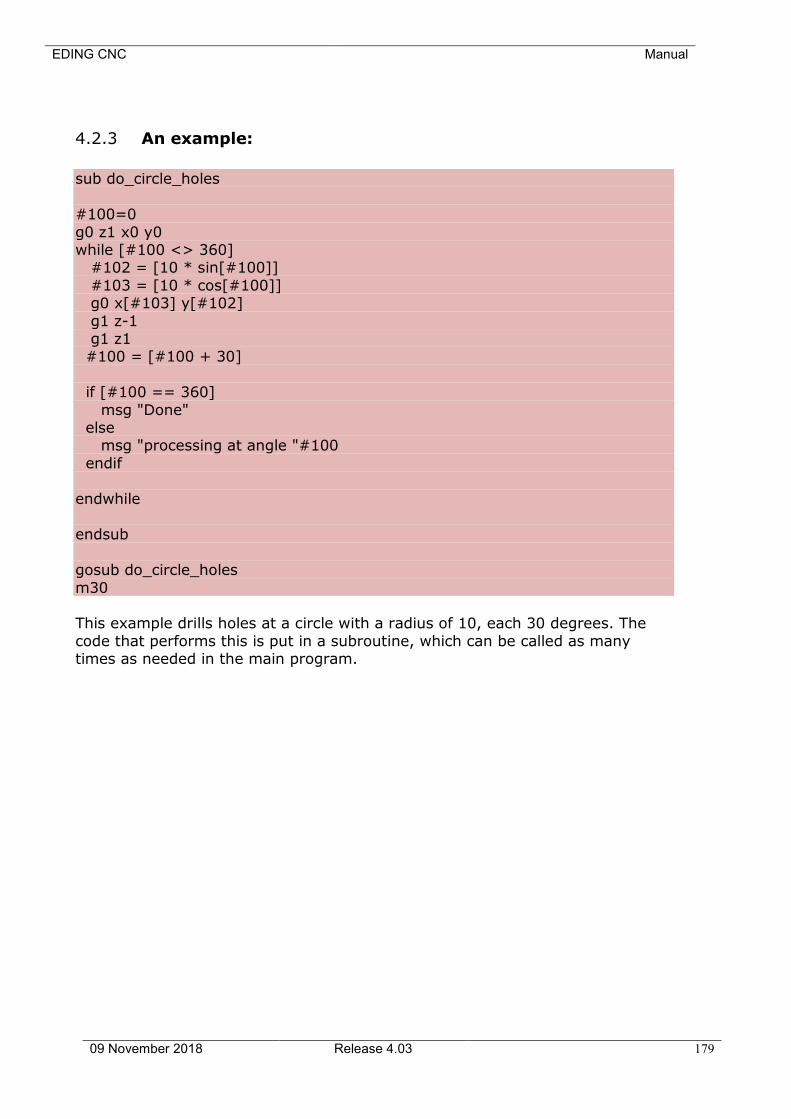
EDING CNC Manual
09 November 2018 Release 4.03 179
4.2.3 An example:
sub do_circle_holes
#100=0
g0 z1 x0 y0 while [#100 <> 360] #102 = [10 * sin[#100]]
#103 = [10 * cos[#100]] g0 x[#103] y[#102]
g1 z-1 g1 z1 #100 = [#100 + 30]
if [#100 == 360]
msg "Done" else msg "processing at angle "#100
endif
endwhile endsub
gosub do_circle_holes
m30 This example drills holes at a circle with a radius of 10, each 30 degrees. The
code that performs this is put in a subroutine, which can be called as many times as needed in the main program.
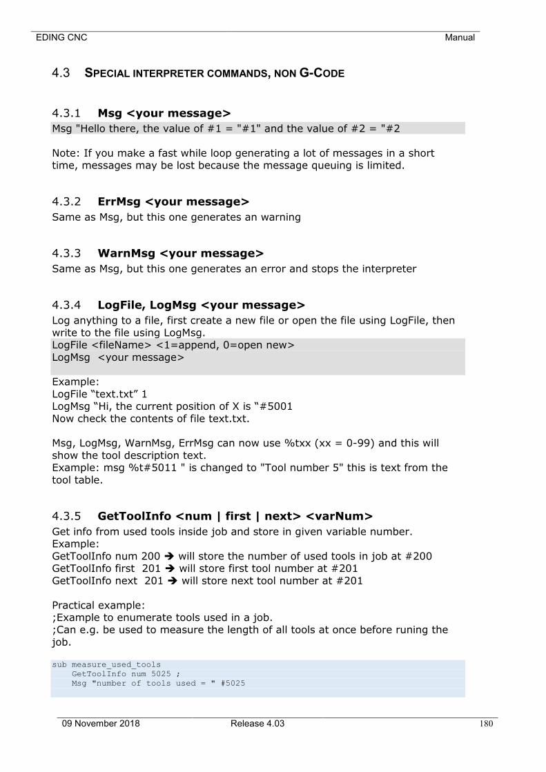
EDING CNC Manual
09 November 2018 Release 4.03 180
4.3 SPECIAL INTERPRETER COMMANDS, NON G-CODE
4.3.1 Msg <your message>
Msg "Hello there, the value of #1 = "#1" and the value of #2 = "#2
Note: If you make a fast while loop generating a lot of messages in a short time, messages may be lost because the message queuing is limited.
4.3.2 ErrMsg <your message>
Same as Msg, but this one generates an warning
4.3.3 WarnMsg <your message>
Same as Msg, but this one generates an error and stops the interpreter
4.3.4 LogFile, LogMsg <your message>
Log anything to a file, first create a new file or open the file using LogFile, then
write to the file using LogMsg. LogFile <fileName> <1=append, 0=open new>
LogMsg <your message> Example:
LogFile “text.txt” 1 LogMsg “Hi, the current position of X is “#5001
Now check the contents of file text.txt. Msg, LogMsg, WarnMsg, ErrMsg can now use %txx (xx = 0-99) and this will
show the tool description text. Example: msg %t#5011 " is changed to "Tool number 5" this is text from the
tool table.
4.3.5 GetToolInfo <num | first | next> <varNum>
Get info from used tools inside job and store in given variable number. Example:
GetToolInfo num 200 ➔ will store the number of used tools in job at #200 GetToolInfo first 201 ➔ will store first tool number at #201
GetToolInfo next 201 ➔ will store next tool number at #201
Practical example: ;Example to enumerate tools used in a job. ;Can e.g. be used to measure the length of all tools at once before runing the
job. sub measure_used_tools
GetToolInfo num 5025 ;
Msg "number of tools used = " #5025
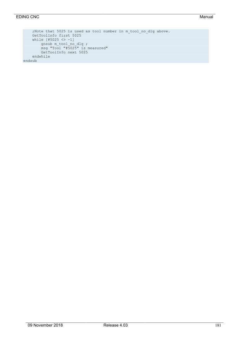
EDING CNC Manual
09 November 2018 Release 4.03 181
;Note that 5025 is used as tool number in m_tool_no_dlg above.
GetToolInfo first 5025
while [#5025 <> -1]
gosub m_tool_no_dlg ;
msg "Tool "#5025" is measured"
GetToolInfo next 5025
endwhile
endsub
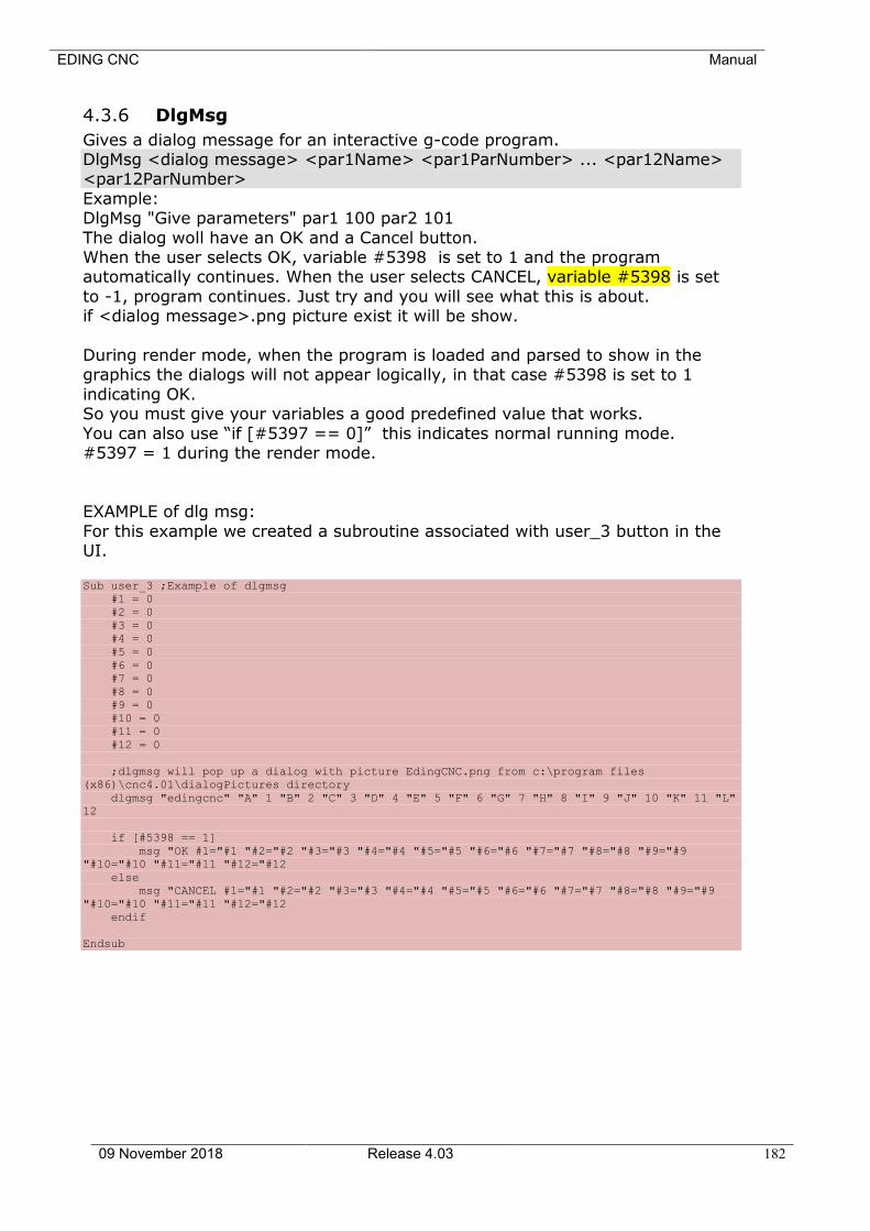
EDING CNC Manual
09 November 2018 Release 4.03 182
4.3.6 DlgMsg
Gives a dialog message for an interactive g-code program. DlgMsg <dialog message> <par1Name> <par1ParNumber> ... <par12Name> <par12ParNumber>
Example: DlgMsg "Give parameters" par1 100 par2 101
The dialog woll have an OK and a Cancel button. When the user selects OK, variable #5398 is set to 1 and the program automatically continues. When the user selects CANCEL, variable #5398 is set
to -1, program continues. Just try and you will see what this is about. if <dialog message>.png picture exist it will be show.
During render mode, when the program is loaded and parsed to show in the graphics the dialogs will not appear logically, in that case #5398 is set to 1
indicating OK. So you must give your variables a good predefined value that works.
You can also use “if [#5397 == 0]” this indicates normal running mode. #5397 = 1 during the render mode.
EXAMPLE of dlg msg:
For this example we created a subroutine associated with user_3 button in the UI. Sub user_3 ;Example of dlgmsg
#1 = 0
#2 = 0
#3 = 0
#4 = 0
#5 = 0
#6 = 0
#7 = 0
#8 = 0
#9 = 0
#10 = 0
#11 = 0
#12 = 0
;dlgmsg will pop up a dialog with picture EdingCNC.png from c:\program files
(x86)\cnc4.01\dialogPictures directory
dlgmsg "edingcnc" "A" 1 "B" 2 "C" 3 "D" 4 "E" 5 "F" 6 "G" 7 "H" 8 "I" 9 "J" 10 "K" 11 "L"
12
if [#5398 == 1]
msg "OK #1="#1 "#2="#2 "#3="#3 "#4="#4 "#5="#5 "#6="#6 "#7="#7 "#8="#8 "#9="#9
"#10="#10 "#11="#11 "#12="#12
else
msg "CANCEL #1="#1 "#2="#2 "#3="#3 "#4="#4 "#5="#5 "#6="#6 "#7="#7 "#8="#8 "#9="#9
"#10="#10 "#11="#11 "#12="#12
endif
Endsub

EDING CNC Manual
09 November 2018 Release 4.03 183
The dialog looks like this:
EDING CNC Manual
09 November 2018 Release 4.03 184
4.3.7 Store position
SP <filename> [0 or 1] This command stores the actual position in given file name.
The extra parameter 0 means create the file, 1 means add to existing file. If only file name is given, the position is added to existing file.
4.3.8 TCAGuard [on | off]
Switches on or off the tool change area guard.
This is used during the rendering process, where the job file is checked for collisions with the machine area and tool change area.
4.3.9 MCAGuard [on | off]
Switches on or off the machine area guard, no collisions will be given. This is used during the rendering process, where the job file is checked for collisions with the machine area and tool change area.
4.3.10 HomeIsEstop [on | off]
This allows to control the homeIsEstop feature. When on, a EStop is generated when one of the home sensors activate.
4.3.11 Exec <external Program> <”parameter”> <Timeout In
Ms.>
This allows to execute an external program within the interpreter and wait until finished. The return code of the program is returned in #5399
Example:
Exec “notepad.exe” “hallo.txt” 60000 This executes notepad.exe and waits 1 minute for it to finish.
An error is generated if it does not finish within given time. The maximum time is 10 minutes.
Whenever a G-Code file is loaded, also the file “macro.cnc” is loaded. In this file you may put your frequently used subroutines, these can be invoked by the G-
Code file through GOSUB subroutineName. The file contains default one special subroutine called “change_tool”, this function is called automatically when a M6 Tx command (Tool change) is
encountered in the G-Code file. With this it is possible to define your own tool change, especially useful when you have an automatic tool changer. You can put
moves and I/O actions there as well as automatic tool length measurement using the probe with G38.2.
The tool change area can be guarded for collision, if it is defined the rendering process will detect eventual collisions and report it. So a normal workpiece
program is not allowed to go through the Tool change Area. The tool change itself is allowed to go to this area. Therefor the change_tool
EDING CNC Manual
09 November 2018 Release 4.03 185
subroutine contains the statement TCAGuard off at the beginning and TCAGuard on at the end.
4.3.12 SetAcc <axisID X-C> <accValue mm/sec^2>
This command allows to change the max acceleration of an axis. Example: SetAcc Y 400 -> Set the max acceleration value for the Y-Axis to
400.
4.3.13 Vacuum [on | off]
Switches on or off vacuum sections that are used this is especially useful for large machines with different vacuum sections. The software will determine in which section will be machined, then this
command will switch only the used sections.
Configuration of the vacuum sections is not available in the GUI settings, and is must be entered in the cnc.ini file, which contains all settings.
Definition of the vacuum sections is manually in the cnc.ini under [VACUUMBED]
automaticMode = 1 numberOfSectionsX = 14
numberOfSectionsY = 1
Automatic mode tells that we use the vacuum functions, and we give the number of sections. In this case there are 14 sections in X that use the whole Y range.
Then for each section the position and size,
section_1_OutputID = 101 ;0: none, 1-10: AUX1-AUX10, GPIO101 GPIO408 section_1_XPosition = 0.000000
section_1_YPosition = 0.000000 section_1_XWidth = 999.000000
section_1_YWidth = 3000.000000
4.3.14 GetJobDistance <index>
Retrieves the traveled distance of the current job. The returned value is stored in #<index>
Example:
GetJobDistance 5399
4.3.15 GetHeightControlVact <index>
EDING CNC Manual
09 November 2018 Release 4.03 186
Retrieves the actual value of the Vact of the height control. The returned value is stored in #<index>
Example:
GetHeighControlVact 5399
Remark: this command will only be executed when the application is in ‘plasma’ or ‘laser’ mode.
4.3.16 GetHeightControlVset <index>
Retrieves the actual value of the Vset of the height control. The returned value is stored in #<index>
Example:
GetHeighControlVset 5399 Remark: this command will only be executed when the application is in ‘plasma’
or ‘laser’ mode.
4.3.17 Service <cmd>
For obtaining and resetting service items.
CMD options: - JOBP, Get Job Progress in meters #5399 - MT_SLS, Get machine running time since last service #5399
- MT_TOT, Get machine running time total in #5399 - TD_SLS, Get traveled distance since last service #5399
- TD_TOT, Get Traveled distance total #5399 - NJ_SLS, Get number of jobs done since last service #5399 - NJ_TOT, Get number of jobs done total #5399
- TTG_PUMP, Get pump action Time to go. - R_TTG_PUMP, Set pump action time to go to 5 seconds, so pump action will
be done after 5 seconds. - R_SERVICE, Reset service counters when service is done.
EDING CNC Manual
09 November 2018 Release 4.03 187
4.3.18 Tool change example
;* http://www.youtube.com/watch?v=_kp0SAeR-Kg
The grey marked code below is already prepared for you in the standard macro.cnc file.
This change_tool subroutine is automatically called when the interpreter encounters e.g.
m6 t1 (If automatic tool change in the setup is switched on).
;This example shows how to make your own tool_changer work.
;It is made for 6 tools and a simple KRESS Tool changer.
;First current tool is dropped, then the new tool is picked
;There is a check whether selected tool is already in the spindle
;Also a check that the tool is within 1-16
;There is a picktool subroutine for each tool and a droptool subroutine for each tool.
;These routines need to be modified to fit your machine and tool changer
sub change_tool
;Switch off guard for tool change area collision
TCAGuard off
;Switch off spindle
m5
;Use #5015 to indicate succesfull toolchange
#5015 = 0 ; Tool change not performed
if [ [#5011] == [#5008] ]
msg "Tool already in spindle"
endif
; check tool in spindle and exit sub
If [ [#5011] <> [#5008] ]
if [[#5011] > 6 ]
; our tool changer supports 6 tools 1-6
errmsg "Please select a tool from 1 to 6."
else
;Drop current tool
If [[#5008] == 0]
GoSub DropTool0
endif
If [[#5008] == 1]
GoSub DropTool1
endif
If [[#5008] == 2]
GoSub DropTool2
endif
If [[#5008] == 3]
GoSub DropTool3
endif
If [[#5008] == 4]
GoSub DropTool4
endif
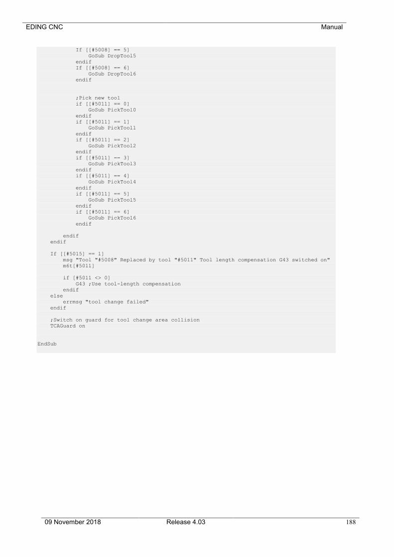
EDING CNC Manual
09 November 2018 Release 4.03 188
If [[#5008] == 5]
GoSub DropTool5
endif
If [[#5008] == 6]
GoSub DropTool6
endif
;Pick new tool
if [[#5011] == 0]
GoSub PickTool0
endif
if [[#5011] == 1]
GoSub PickTool1
endif
if [[#5011] == 2]
GoSub PickTool2
endif
if [[#5011] == 3]
GoSub PickTool3
endif
if [[#5011] == 4]
GoSub PickTool4
endif
if [[#5011] == 5]
GoSub PickTool5
endif
if [[#5011] == 6]
GoSub PickTool6
endif
endif
endif
If [[#5015] == 1]
msg "Tool "#5008" Replaced by tool "#5011" Tool length compensation G43 switched on"
m6t[#5011]
if [#5011 <> 0]
G43 ;Use tool-length compensation
endif
else
errmsg "tool change failed"
endif
;Switch on guard for tool change area collision
TCAGuard on
EndSub

EDING CNC Manual
09 November 2018 Release 4.03 189
The code below is also inside file macro.cnc, for each tool there is a DropTool sub-routine and a Pick-tool sun-routine. DropTool makes the movements and IO
for putting the tool from spindle in the tool holder. PickTool makes the movements and I/O to pick the tool from the tool holder and put it in the
spindle.
These subroutines below are machine dependent and need to be filled in by yourself.
This example works only for the Kress Tool changer.
;Drop tool subroutines, these put the tool in spindle in the tool-holder
Sub DropTool0
msg "Dropping tool 0"
;Tool 0 is no tool, so we just open yhe tool station here for PickTool which comes next
M54P3 ;Open toolstation OUTPUT AUX3
G4P1 ;Wait 1 seconds
endsub
Sub DropTool1
msg "Dropping tool 1"
M5
G53G0Z100 ;Z up 110 is and machinebed is zero
G53G0X825.00Y173.00 ;Move just before drop place
M54P3 ;Open toolstation
G4P1 ;Wait 1 seconds
G53G1X867.206Y173.156F220 ;Move into drop place
g53G0Z60 ;Move down fast but not fully to the endposition
g53G01Z32.000F120 ;Move down the last mm slower
M54P1 ;AUX1 ON air pressure toolchange
G4P1 ;Wait 1 second
G53G01Z45F100 ;Move up slowly to move free from toolstation
M55P1 ;AUX1 off, tool dropped
G53G0Z100 ;Further up and done with dropping tool
endsub
Sub DropTool2
msg "Dropping tool 2"
M5
G53G0Z100 ;Z up 110 is and machinebed is zero
G53G0X825.00Y208.00 ;Move just before drop place
M54P3 ;Open toolstation
G4P01 ;Wait 1 seconds
G53G1X867.200Y208.156F220 ;Move into drop place
g53G0Z60 ;Move down fast but not fully to the endposition
g53G01Z32.000F120 ;Move down the last mm slower
M54P1 ;AUX1 ON air pressure toolchange
G4P1 ;Wait 1 second
G53G01Z45F100 ;Move up slowly to move free from toolstation
M55P1 ;AUX1 off, tool dropped
G53G0Z100 ;Further up and done with dropping tool
endsub
Sub DropTool3
msg "Dropping tool 3"
M5
G53G0Z100 ;Z up 110 is and machinebed is zero
G53G0X825.00Y243.00 ;Move just before drop place
M54P3 ;Open toolstation
G4P01 ;Wait 1 seconds
G53G1X867.116Y243.156F220 ;Move into drop place
G53G0Z60 ;Move down fast but not fully to the endposition
G53G01Z32.000F120 ;Move down the last mm slower
M54P1 ;AUX1 ON air pressure toolchange
G4P1 ;Wait 1 second
G53G01Z45F100 ;Move up slowly to move free from toolstation
M55P1 ;AUX1 off, tool dropped
G53G0Z100 ;Further up and done with dropping tool
endsub
Sub DropTool4
msg "Dropping tool 4"
M5
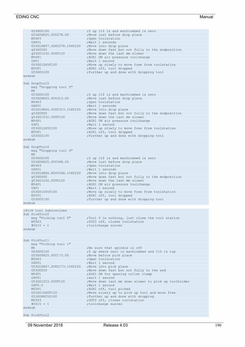
EDING CNC Manual
09 November 2018 Release 4.03 190
G53G0Z100 ;Z up 110 is and machinebed is zero
G53G0X825.00Y278.00 ;Move just before drop place
M54P3 ;Open toolstation
G4P01 ;Wait 1 seconds
G53G1X867.026Y278.156F220 ;Move into drop place
g53G0Z60 ;Move down fast but not fully to the endposition
g53G01Z32.000F120 ;Move down the last mm slower
M54P1 ;AUX1 ON air pressure toolchange
G4P1 ;Wait 1 second
G53G01Z45F100 ;Move up slowly to move free from toolstation
M55P1 ;AUX1 off, tool dropped
G53G0Z100 ;Further up and done with dropping tool
endsub
Sub DropTool5
msg "Dropping tool 5"
M5
G53G0Z100 ;Z up 110 is and machinebed is zero
G53G0X825.00Y313.00 ;Move just before drop place
M54P3 ;Open toolstation
G4P01 ;Wait 1 seconds
G53G1X866.936Y313.156F220 ;Move into drop place
g53G0Z60 ;Move down fast but not fully to the endposition
g53G01Z32.000F120 ;Move down the last mm slower
M54P1 ;AUX1 ON air pressure toolchange
G4P1 ;Wait 1 second
G53G01Z45f100 ;Move up slowly to move free from toolstation
M55P1 ;AUX1 off, tool dropped
G53G0Z100 ;Further up and done with dropping tool
endsub
Sub DropTool6
msg "Dropping tool 6"
M5
G53G0Z100 ;Z up 110 is and machinebed is zero
G53G0X825.00Y348.00 ;Move just before drop place
M54P3 ;Open toolstation
G4P01 ;Wait 1 seconds
G53G1X866.850Y348.156F220 ;Move into drop place
g53G0Z60 ;Move down fast but not fully to the endposition
g53G01Z32.000F120 ;Move down the last mm slower
M54P1 ;AUX1 ON air pressure toolchange
G4P1 ;Wait 1 second
G53G01Z45f100 ;Move up slowly to move free from toolstation
M55P1 ;AUX1 off, tool dropped
G53G0Z100 ;Further up and done with dropping tool
endsub
;Pick tool subroutines
Sub PickTool0
msg "Picking tool 0" ;Tool 0 is nothing, just close the tool station
M55P3 ;OUT3 off, closes toolstation
#5015 = 1 ;toolchange succes
endsub
Sub PickTool1
msg "Picking tool 1"
M5 ;Be sure that spindle is off
G53G0Z100 ;Z up where zero is machinebed and 110 is top
G53G0X825.00Y173.00 ;Move before pick place
M54P3 ;Open toolstation
G4P01 ;Wait 1 second
G53G1X867.206Y173.156F220 ;Move into pick place
G53G0Z50 ;Move down fast but not fully to the end
M54P1 ;AUX1 ON for opening collet clamp
G4P01 ;wait 1 second
G53G01Z23.000F120 ;Move down last mm down slower to pick up toolholder
G4P0.5 ;Wait 1 second
M55P1 ;AUX1 off, tool picked
G53G01Z60F120 ;Move slowly up to pick up tool and move free
G53G0X825Z100 ;Further up and done with dropping
M55P3 ;OUT3 off, closes toolstation
#5015 = 1 ;toolchange succes
endsub
Sub PickTool2
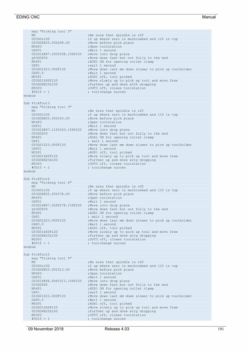
EDING CNC Manual
09 November 2018 Release 4.03 191
msg "Picking tool 2"
M5 ;Be sure that spindle is off
G53G0z100 ;Z up where zero is machinebed and 110 is top
G53G0X825.00Y208.00 ;Move before pick place
M54P3 ;Open toolstation
G4P01 ;Wait 1 second
G53G1X867.200Y208.156F220 ;Move into drop place
g53G0Z50 ;Move down fast but not fully to the end
M54P1 ;AUX1 ON for opening collet clamp
G4P1 ;wait 1 second
G53G01Z23.000F120 ;Move down last mm down slower to pick up toolholder
G4P0.5 ;Wait 1 second
M55P1 ;AUX1 off, tool picked
G53G01Z60F120 ;Move slowly up to pick up tool and move free
G53G0X825Z100 ;Further up and done with dropping
M55P3 ;OUT3 off, closes toolstation
#5015 = 1 ; toolchange succes
endsub
Sub PickTool3
msg "Picking tool 3"
M5 ;Be sure that spindle is off
G53G0z100 ;Z up where zero is machinebed and 110 is top
G53G0X825.00Y243.00 ;Move before pick place
M54P3 ;Open toolstation
G4P01 ;Wait 1 second
G53G1X867.116Y243.156F220 ;Move into drop place
G53G0Z50 ;Move down fast but not fully to the end
M54P1 ;AUX1 ON for opening collet clamp
G4P1 ; wait 1 second
G53G01Z23.000F120 ;Move down last mm down slower to pick up toolholder
G4P01 ;Wait 1 second
M55P1 ;AUX1 off, tool picked
G53G01Z60F120 ;Move slowly up to pick up tool and move free
G53G0X825Z100 ;Further up and done witg dropping
M55P3 ;OUT3 off, closes toolstation
#5015 = 1 ; toolchange succes
endsub
Sub PickTool4
msg "Picking tool 4"
M5 ;Be sure that spindle is off
G53G0z100 ;Z up where zero is machinebed and 110 is top
G53G0X825.00Y278.00 ;Move before pick place
M54P3 ;Open toolstation
G4P01 ;Wait 1 second
G53G1X867.026Y278.156F220 ;Move into drop place
g53G0Z50 ;Move down fast but not fully to the end
M54P1 ;AUX1 ON for opening collet clamp
G4P1 ; wait 1 second
G53G01Z23.000F120 ;Move down last mm down slower to pick up toolholder
G4P0.5 ;Wait 1 second
M55P1 ;AUX1 off, tool picked
G53G01Z60F120 ;Move slowly up to pick up tool and move free
G53G0X825Z100 ;Further up and done witg dropping
M55P3 ;OUT3 off, closes toolstation
#5015 = 1 ; toolchange succes
endsub
Sub PickTool5
msg "Picking tool 5"
M5 ;Be sure that spindle is off
G53G0z100 ;Z up where zero is machinebed and 110 is top
G53G0X825.00Y313.00 ;Move before pick place
M54P3 ;Open toolstation
G4P01 ;Wait 1 second
G53G1X866.936Y313.156F220 ;Move into drop place
G53G0Z60 ;Move down fast but not fully to the end
M54P1 ;AUX1 ON for opening collet clamp
G4P1 ;wait 1 second
G53G01Z23.000F120 ;Move down last mm down slower to pick up toolholder
G4P0.5 ;Wait 1 second
M55P1 ;AUX1 off, tool picked
G53G01Z60F120 ;Move slowly up to pick up tool and move free
G53G0X825Z100 ;Further up and done witg dropping
M55P3 ;OUT3 off, closes toolstation
#5015 = 1 ; toolchange succes
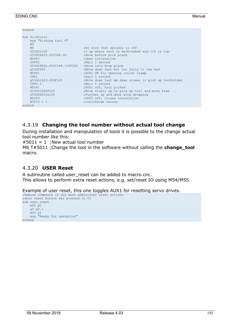
EDING CNC Manual
09 November 2018 Release 4.03 192
endsub
Sub PickTool6
msg "Picking tool 6"
M5
M5 ;Be sure that spindle is off
G53G0z100 ;Z up where zero is machinebed and 110 is top
G53G0X825.00Y348.00 ;Move before pick place
M54P3 ;Open toolstation
G4P01 ;Wait 1 second
G53G1X866.850Y348.156F220 ;Move into drop place
g53G0Z60 ;Move down fast but not fully to the end
M54P1 ;AUX1 ON for opening collet clamp
G4P1 ;wait 1 second
g53G01Z23.000F120 ;Move down last mm down slower to pick up toolholder
G4P0.5 ;Wait 1 second
M55P1 ;AUX1 off, tool picked
G53G01Z60F120 ;Move slowly up to pick up tool and move free
G53G0X825Z100 ;Further up and done witg dropping
M55P3 ;OUT3 off, closes toolstation
#5015 = 1 ;toolchange succes
endsub
4.3.19 Changing the tool number without actual tool change
During installation and manipulation of tools it is possible to the change actual tool number like this: #5011 = 1 ;New actual tool number
M6 T#5011 ;Change the tool in the software without calling the change_tool macro.
4.3.20 USER Reset
A subroutine called user_reset can be added to macro.cnc.
This allows to perform extra reset actions, e.g. set/reset IO using M54/M55.
Example of user reset, this one toggles AUX1 for resetting servo drives. ;Remove comments if you want additional reset actions
;when reset button was pressed in UI
sub user_reset
m54 p1
g4 p0.1
m55 p1
msg "Ready for operation"
endsub

EDING CNC Manual
09 November 2018 Release 4.03 193
4.4 RUN BEHAVIOR DURING SIMULATION AND RENDER
Simulation is the software mode when there is no hardware connected. Render is performed during loading of a g-code file, the file is run by the
interpreter while generating output for the graphic. During this no actions to the machine are applied, no motion and no IO, only checks if the g-code is valid and
stay’s within the machine limits. If there is advanced macro programming, e.g. because the machine has automatic tool change, there it is important to take into account that in
simulation and render mode no machine actions take place.
4.4.1 Example a check with error that we want to see always
Suppose we have a machine with a 6 tool automatic tool changer. A check is programmed hat generates an error if a g-code file is loaded that tries to
change tool to a number that we do not have: if [#5011 > 6]
ErrMsg “Please select a tool in range 1-6”
Else
..
;Code to perform the tool change
Endif
It is logic that we want this “ErrMsg …” line to be executed always, when
running but also in simulation mode and when loading the file.
4.4.2 Example a check with error showing only when running
sub check_airpresure
m56 p5
if [#5399 == 0]
errmsg "Error, No Air pressure"
else
msg "Air Presure OK"
endif
endsub
This check on air pressure will not work correctly while loading a g-code file or
while the system is in simulation mode, because no actual inputs are read. sub check_airpresure
;;Check only if not rendering and not simulation
if [[#5380 == 0] and [#5397 == 0]]
m56 p5
if [#5399 == 0]
errmsg "Error, No Air pressure"
else
msg "Air Presure OK"
endif
endif
endsub
Here we see the modification to make the on the air pressure sensor input 5 simulation and render proof, the check is only performed when we are not in
render or simulation mode, only an extra if statement that checks #5380 (1 when simulation mode) and #5397 (1 when rendering) is added.

EDING CNC Manual
09 November 2018 Release 4.03 194
5 Cutter Radius Compensation This appendix discusses cutter radius compensation. It is intended for NC
programmers and machine operators.
See chapter 5 for additional information on cutter radius compensation.
EDING CNC Manual
09 November 2018 Release 4.03 195
5.1 INTRODUCTION
The cutter radius compensation capabilities of the Interpreter enable the programmer to specify that a cutter should travel to the right or left of an
open or closed contour in the XY-plane composed of arcs of circles and straight line segments.
Cutter radius compensation is performed only with the XY-plane active. All the figures in this appendix, therefore, show projections on the XY-plane.
Where the adjacent sides of remaining material meet at a corner, there
are two common ways to handle the tool path. The tool may pass in an arc around the corner, or the tool path may continue straight in the direction it was going along the first side until it reaches a point where it
changes direction to go straight along the second side. Figure A-1 shows these two types of path. On Figure A-1:
• Uncut material is shaded in the figures. Note that the inner triangles have the same shape with both tool paths.
• The white areas are the areas cleared by the tool.
• The lines in the center of the white areas represent the path of the tip of a cutting tool.
• The tool is the cross-hatched circles. Both paths will clear away material near the shaded triangle and leave the
shaded triangle uncut. When the Interpreter performs cutter radius compensation, the tool path is rounded at the corners, as shown on the
left in Figure A-1. In the method on the right (the one not used), the tool does not stay in contact with the shaded triangle at sharp corners, and
more material than necessary is removed. There are also two alternatives for the path that is programmed in NC
code during cutter radius compensation. The programmed path may be either (1) the edge of the material to remain uncut (for example, the edge
of the inner triangle on the left of Figure A-1), or (2) the nominal tool path (for example, the tool path on the left side of Figure A-1). The nominal tool path is the path that would be used if the tool were exactly the
intended size. The Interpreter will handle both cases without being told which one it is. The two cases are very similar, but different enough that
they are described in separate sections see below.
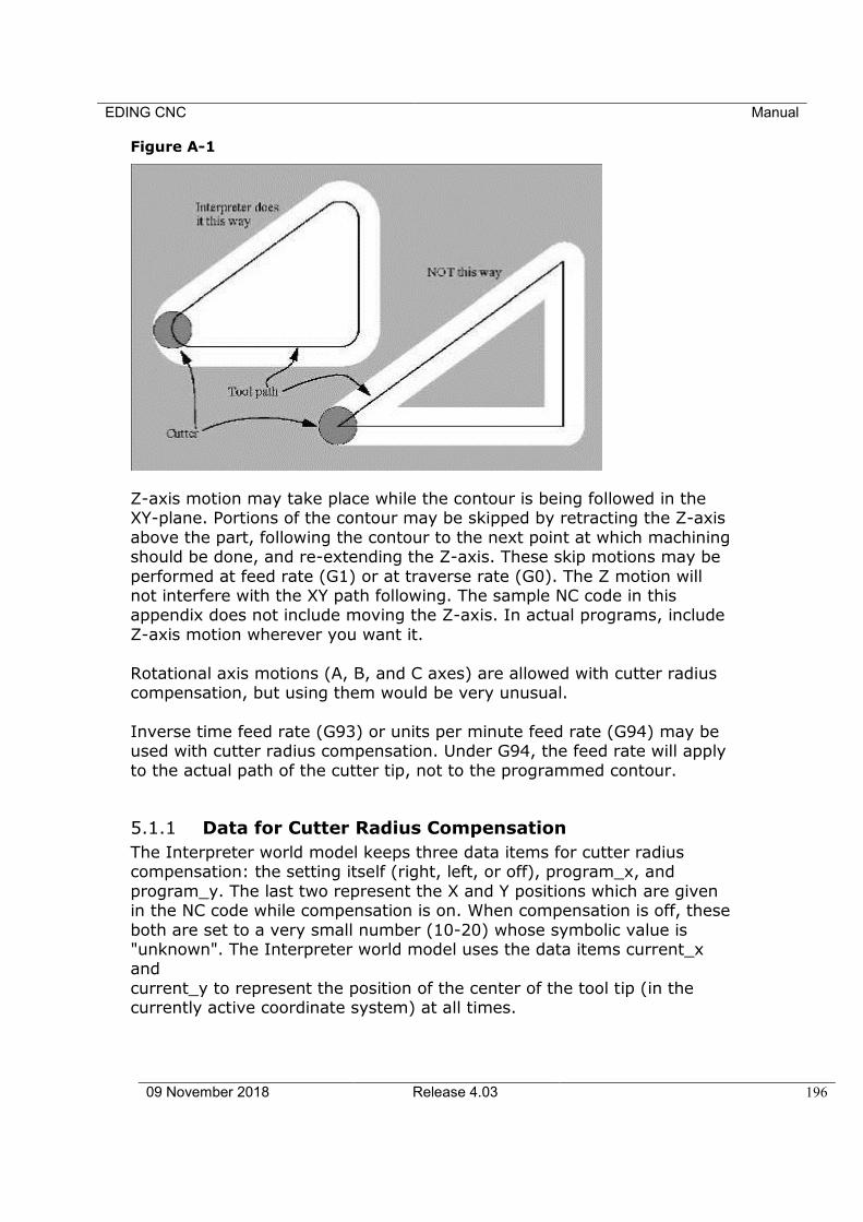
EDING CNC Manual
09 November 2018 Release 4.03 196
Figure A-1
Z-axis motion may take place while the contour is being followed in the XY-plane. Portions of the contour may be skipped by retracting the Z-axis
above the part, following the contour to the next point at which machining should be done, and re-extending the Z-axis. These skip motions may be
performed at feed rate (G1) or at traverse rate (G0). The Z motion will not interfere with the XY path following. The sample NC code in this appendix does not include moving the Z-axis. In actual programs, include
Z-axis motion wherever you want it.
Rotational axis motions (A, B, and C axes) are allowed with cutter radius compensation, but using them would be very unusual.
Inverse time feed rate (G93) or units per minute feed rate (G94) may be used with cutter radius compensation. Under G94, the feed rate will apply
to the actual path of the cutter tip, not to the programmed contour.
5.1.1 Data for Cutter Radius Compensation
The Interpreter world model keeps three data items for cutter radius compensation: the setting itself (right, left, or off), program_x, and
program_y. The last two represent the X and Y positions which are given in the NC code while compensation is on. When compensation is off, these
both are set to a very small number (10-20) whose symbolic value is "unknown". The Interpreter world model uses the data items current_x and
current_y to represent the position of the center of the tool tip (in the currently active coordinate system) at all times.

EDING CNC Manual
09 November 2018 Release 4.03 197
5.2 PROGRAMMING INSTRUCTIONS
5.2.1 Turning Cutter Radius Compensation On
To start cutter radius compensation keeping the tool to the left of the contour, program G41 D…. The D word is optional (see "Use of D Number", just below).
To start cutter radius compensation keeping the tool to the right of the
contour, program G42 D… . In Figure A-1, for example, if G41 were programmed, the tool would move
clockwise around the triangle, so that the tool is always to the left of the triangle when facing in the direction of travel. If G42 were programmed,
the tool would stay right of the triangle and move counter clockwise around the triangle.
5.2.2 Turning Cutter Radius Compensation Off
To stop cutter radius compensation, program G40. It is OK to turn
compensation off when it is already off.
5.2.3 Sequencing
If G40, G41, or G42 is programmed on the same line as tool motion, cutter
compensation will be turned on or off before the motion is made. To make the motion come first, the motion must be programmed on a separate,
previous line of code.
5.2.4 Use of D Number
Programming a D word with G41 or G42, is optional. If a D number is programmed, it must be a non-negative integer. It
represents the slot number of the tool whose radius (half the diameter given in the tool table) will be used, or it may be zero (which is not a slot
number). If it is zero, the value of the radius will also be zero. Any slot in the tool table may be selected. The D number does not have to be the same as the slot number of the tool in the spindle, although it is rarely
useful for it not to be. If a D number is not programmed, the slot number of the tool in the
spindle will be used as the D number.
5.2.5 Material Edge Contour
When the contour is the edge of the material, the outline of the edge is described
in the NC program.
EDING CNC Manual
09 November 2018 Release 4.03 198
For a material edge contour, the value for the diameter in the tool table is the actual value of the diameter of the tool. The value in the table must
be positive. The NC code for a material edge contour is the same regardless of the (actual or intended) diameter of the tool.
5.2.6 Programming Entry Moves
In general, two pre-entry moves and one entry move are needed to begin
compensation correctly. However, if there is a convex corner on the contour, a simpler method is available using zero or one pre-entry move
and one entry move. The general method, which will work in all situations, is described first. We assume here that the programmer knows what the contour is already and has the job of
adding entry moves.
A.1.1.1 GENERAL METHOD
The general method includes programming two pre-entry moves and one entry move. See Figure A-2. The shaded area is the remaining material. It
has no corners, so the simple method cannot be used. The dotted line is the programmed path. The solid line is the actual path of the tool tip. Both
paths go clockwise around the remaining material. A cutter one unit in diameter is shown part way around the path. The black dots mark points at the beginning or end of programmed or actual moves. The figure shows
the second pre-entry move but not the first, since the beginning point of the first pre-entry move could be anywhere.
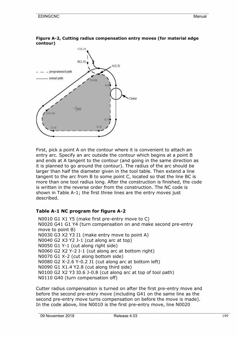
EDINGCNC Manual
09 November 2018 Release 4.03 199
Figure A-2, Cutting radius compensation entry moves (for material edge
contour)
First, pick a point A on the contour where it is convenient to attach an entry arc. Specify an arc outside the contour which begins at a point B
and ends at A tangent to the contour (and going in the same direction as it is planned to go around the contour). The radius of the arc should be
larger than half the diameter given in the tool table. Then extend a line tangent to the arc from B to some point C, located so that the line BC is more than one tool radius long. After the construction is finished, the code
is written in the reverse order from the construction. The NC code is shown in Table A-1; the first three lines are the entry moves just
described.
Table A-1 NC program for figure A-2
N0010 G1 X1 Y5 (make first pre-entry move to C) N0020 G41 G1 Y4 (turn compensation on and make second pre-entry
move to point B) N0030 G3 X2 Y3 I1 (make entry move to point A) N0040 G2 X3 Y2 J-1 (cut along arc at top)
N0050 G1 Y-1 (cut along right side) N0060 G2 X2 Y-2 I-1 (cut along arc at bottom right)
N0070 G1 X-2 (cut along bottom side) N0080 G2 X-2.6 Y-0.2 J1 (cut along arc at bottom left) N0090 G1 X1.4 Y2.8 (cut along third side)
N0100 G2 X2 Y3 I0.6 J-0.8 (cut along arc at top of tool path) N0110 G40 (turn compensation off)
Cutter radius compensation is turned on after the first pre-entry move and
before the second pre-entry move (including G41 on the same line as the second pre-entry move turns compensation on before the move is made). In the code above, line N0010 is the first pre-entry move, line N0020

EDINGCNC Manual
09 November 2018 Release 4.03 200
turns compensation on and makes the second pre-entry move, and line N0030 makes the entry move.
A.1.1.2 SIMPLE METHOD
If there is a convex (sticking out, not in) corner somewhere on the contour, a simpler method of making an entry is available. See Figure A-3.
First, pick a convex corner. There is only one corner in Figure A-3. It is at
A, and it is convex. Decide which way you want to go along the contour from A. In our example we are keeping the tool to the left of the remaining material and going clockwise. Extend the side to be cut (DA in
the figure) to divide the area outside the material near A into two regions; DA extended is the dotted line AC on the figure. Make a pre-entry move to
anywhere in the region on the same side of DC as the remaining material (point B on the figure) and not so close to the remaining material that the tool is cutting into it. Anywhere in the diagonally shaded area of the figure
(or above or to the left of that area) is OK. If the tool is already in region, no pre-entry move is needed. Write a line of NC code to move to B, if
necessary. Then write a line of NC code for a straight entry move that turns compensation on and goes to point A. If B is at (1.5, 4), the two lines of code for the pre-entry and entry moves
would be:
N0010 G1 X1.5 Y4 (move to B)
N0020 G41 G1 X3 Y3 (turn compensation on and make entry move to A)
These two lines would be followed by four lines identical to lines N0050 to
N0080 from Table A-1, but the end of the program would be different since the shape of remaining material is different.
It would be OK for B to be on line AC. In fact, B could be placed on the extension outside the part of any straight side of the part. B could be
placed on EF extended to the right (but not to the left, for going clockwise), for example.
If DA were an arc, not a straight line, the two lines of code above would
still be suitable. In this case, the dotted line extending DA should be tangent to DA at A. Figure A-3 Simpler cutter radius compensation entry move (for material
edge contour)
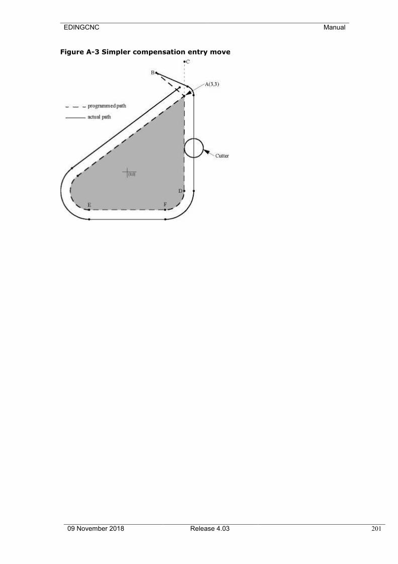
EDINGCNC Manual
09 November 2018 Release 4.03 201
Figure A-3 Simpler compensation entry move
EDINGCNC Manual
09 November 2018 Release 4.03 202
5.3 NOMINAL PATH CONTOUR
When the contour is a nominal path contour (the path a tool with exactly
the intended diameter would take), the tool path is described in the NC program. It is expected that (except for during the entry moves) the path is intended to create some part geometry. The path may be generated
manually or by a post-processor, considering the part geometry which is intended to be made. For the Interpreter to work, the tool path must be
such that the tool stays in contact with the edge of the part geometry, as shown on the left side of Figure A-1. If a path of the sort shown on the right of Figure A-1 is used, in which the tool does not stay in contact with
the part geometry all the time, the Interpreter will not be able to compensate properly when undersized tools are used. A nominal path
contour has no corners, so the simple method just described will not work. For a nominal path contour, the value for the cutter diameter in the tool
table will be a small positive number if the selected tool is slightly oversized and will be a small negative number if the tool is slightly
undersized. If a cutter diameter value is negative, the Interpreter compensates on the other side of the contour from the one programmed and uses the absolute value of the given diameter. If the actual tool is the
correct size, the value in the table should be zero. Suppose, for example, the diameter of the cutter currently in the spindle is 0.97, and the
diameter assumed in generating the tool path was 1.0. Then the value in the tool table for the diameter for this tool should be -0.03.
The nominal tool path needs to be programmed so that it will work with the largest and smallest tools expected to be actually used. We will call
the difference between the radius of the largest expected tool and the intended radius of the tool the "maximum
radius difference." This is usually a small number. The method includes programming two pre-entry moves and one entry
moves. See Figure A-4. The shaded area is the remaining material. The dashed line is the programmed tool path. The solid line is the actual path
of the tool tip. Both paths go clockwise around the remaining material. The actual path is to the right of the programmed path even though G41 was programmed, because the diameter value is negative. On the figure,
the distance between the two paths is larger than would normally be expected. The 1-inch diameter tool is shown part way around the path.
The black dots mark points at the beginning or end of programmed moves. The corresponding points on the actual path have not been marked. The actual path will have a very small additional arc near point B
unless the tool diameter is exactly the size intended. The figure shows the second pre-entry move but not the first, since the beginning point of the
first pre-entry move could be anywhere. First, pick a point A on the contour where it is convenient to attach an
entry arc. Specify an arc outside the contour which begins at a point B and ends at A tangent to the contour (and going in the same direction as
it is planned to go around the contour). The radius of the arc should be larger than the maximum radius difference. Then extend a line tangent to
EDINGCNC Manual
09 November 2018 Release 4.03 203
the arc from B to some point C, located so that the length of line BC is more than the maximum radius difference. After the construction is
finished, the code is written in the reverse order from the construction. The NC code is shown in Table A-2; the first three lines are the entry
moves just described.
Table A-2 NC program for Figure A-4
N0010 G1 X1.5 Y5 (make first pre-entry move to C) N0020 G41 G1 Y4 (turn compensation on and make second pre-entry
move to point B) N0030 G3 X2 Y3.5 I0.5 (make entry move to point A) N0040 G2 X3.5 Y2 J-1.5 (cut along arc at top)
N0050 G1 Y-1 (cut along right side) N0060 G2 X2 Y-2.5 I-1.5 (cut along arc at bottom right)
N0070 G1 X-2 (cut along bottom side) N0080 G2 X-2.9 Y0.2 J1.5 (cut along arc at bottom left) N0090 G1 X1.1 Y3.2 (cut along third side)
N0100 G2 X2 Y3.5 I0.9 J-1.2 (cut along arc at top of tool path) N0110 G40 (turn compensation off)
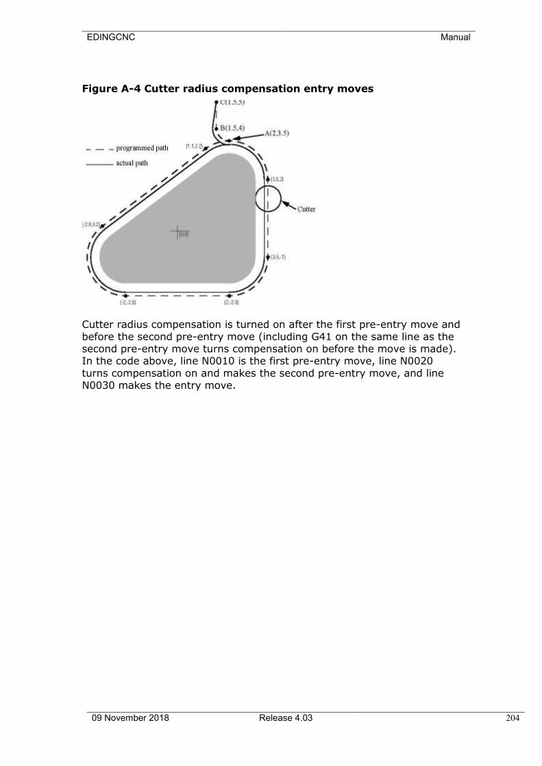
EDINGCNC Manual
09 November 2018 Release 4.03 204
Figure A-4 Cutter radius compensation entry moves
Cutter radius compensation is turned on after the first pre-entry move and
before the second pre-entry move (including G41 on the same line as the second pre-entry move turns compensation on before the move is made). In the code above, line N0010 is the first pre-entry move, line N0020
turns compensation on and makes the second pre-entry move, and line N0030 makes the entry move.
EDINGCNC Manual
09 November 2018 Release 4.03 205
5.4 PROGRAMMING ERRORS AND LIMITATIONS
The Interpreter will issue the following error messages involving cutter
radius compensation. In addition to these, there are several bug messages related to cutter compensation, but they should never occur.
1. Cannot change axis offsets with cutter radius comp 2. Cannot change units with cutter radius comp
3. Cannot probe with cutter radius comp on 4. Cannot turn cutter radius comp on out of xy-plane 5. Cannot turn cutter radius comp on when on
6. Cannot use g28 or g30 with cutter radius comp 7. Cannot use g53 with cutter radius comp
8. Cannot use xz-plane with cutter radius comp 9. Cannot use yz-plane with cutter radius comp 10.Concave corner with cutter radius comp
11.Cutter gouging with cutter radius comp 12.D word with no g41 or g42
13.Multiple d words on one line 14.Negative d word tool radius index used 15.Tool radius index too big
16.Tool radius not less than arc radius with comp 17.Two g codes used from same modal group.
Most of these are self-explanatory. For those that require explanation, an explanation is given below.
Changing a tool while cutter radius compensation is on is not treated as
an error, although it is unlikely this would be done intentionally. The radius used when cutter radius compensation was first turned on will
continue to be used until compensation is turned off, even though a new tool is actually being used.
A.1.2 Concave Corner and Tool Radius Too Big (10 and 16) When cutter radius compensation is on, it must be physically possible for
a circle whose radius is the half the diameter given in the tool table to be tangent to the contour at all points of the contour. In particular, the Interpreter treats concave corners and concave arcs into which the circle
will not fit as errors, since the circle cannot be kept tangent to the contour in these situations. See Figure A-5. This error detection does not limit the
shapes which can be cut, but it does require that the programmer specify the actual shape to be cut (or path to be followed), not an approximation. In this respect, the NIST
RS274/NGC Interpreter differs from interpreters used with many other controllers, which often allow these errors silently and either gouge the
part or round the corner. concave corner concave arc too small
-tool does not fit -tool does not fit

EDINGCNC Manual
09 November 2018 Release 4.03 206
Figure A-5, Two cutter radius compensation errors
In both examples, the line represents a contour, and the circle represents
the cross section of a tool following the contour using cutter radius compensation (tangent to one side of the path.)
A.1.3 Cannot Turn Cutter Radius Comp on When On (5) If cutter radius compensation has already been turned on, it cannot be
turned on again. It must be turned off first; then it can be turned on again. It is not necessary to move the
cutter between turning compensation off and back on, but the move after turning it back on will be treated as a first move, as described below. It is not possible to change from one cutter radius index to another while
compensation is on because of the combined effect of rules 5 and 12. It is also not possible to switch compensation from one side to another while
compensation is on. A.1.4 Cutter Gouging (11)
If the tool is already covering up the next XY destination point when cutter radius compensation is turned on, the gouging message is given when the
line of NC code which gives the point is reached. In this situation, the tool is already cutting into material it should not cut. More details are given in Section
A.6.
A.1.5 Tool Radius Index Too Big (15) If a D word is programmed that is larger than the number of tool carousel slots, this error message is given. In the SAI, the number of slots is 68.
A.1.6 Two G Codes Used from Same Modal Group (17)
This is a generic message used for many sets of G codes. As applied to cutter radius compensation, it means that more than one of G40, G41, and G42
appears on a line of NC code. This is not allowed.
A.2 First Move into Cutter Compensation The algorithm used for the first move after cutter radius compensation is
turned on, when the first move is a straight line, is to draw a straight line from the programmed destination point which is tangent to a circle whose center is at the current point and whose radius is the radius of the tool.
The destination point of the tool tip is then found as the center of a circle of the same radius tangent to the tangent line at the destination point. If
the programmed point is inside the initial cross section of the tool (the circle on the left), an error is signaled. The concept of the algorithm is shown in Figure A-6.
The function that locates the destination point actually takes a computational shortcut based on the fact that the line (not drawn on the
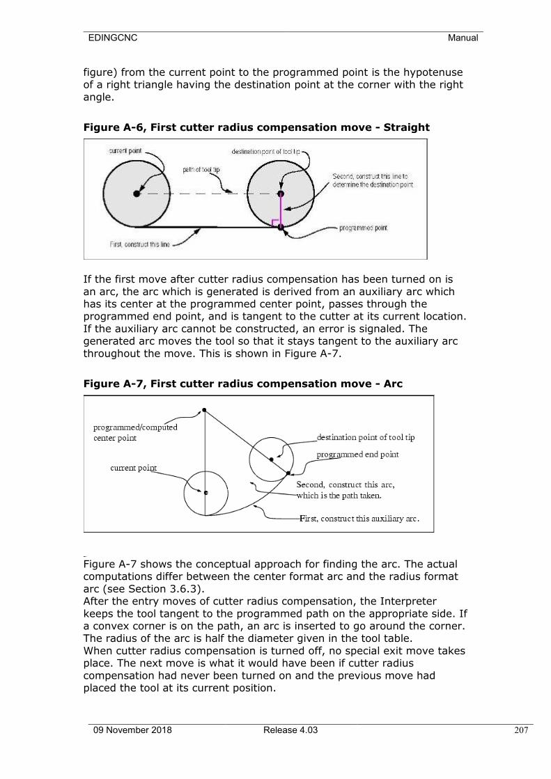
EDINGCNC Manual
09 November 2018 Release 4.03 207
figure) from the current point to the programmed point is the hypotenuse of a right triangle having the destination point at the corner with the right
angle.
Figure A-6, First cutter radius compensation move - Straight
If the first move after cutter radius compensation has been turned on is
an arc, the arc which is generated is derived from an auxiliary arc which has its center at the programmed center point, passes through the programmed end point, and is tangent to the cutter at its current location.
If the auxiliary arc cannot be constructed, an error is signaled. The generated arc moves the tool so that it stays tangent to the auxiliary arc
throughout the move. This is shown in Figure A-7.
Figure A-7, First cutter radius compensation move - Arc
Figure A-7 shows the conceptual approach for finding the arc. The actual computations differ between the center format arc and the radius format
arc (see Section 3.6.3). After the entry moves of cutter radius compensation, the Interpreter
keeps the tool tangent to the programmed path on the appropriate side. If a convex corner is on the path, an arc is inserted to go around the corner. The radius of the arc is half the diameter given in the tool table.
When cutter radius compensation is turned off, no special exit move takes place. The next move is what it would have been if cutter radius
compensation had never been turned on and the previous move had placed the tool at its current position.
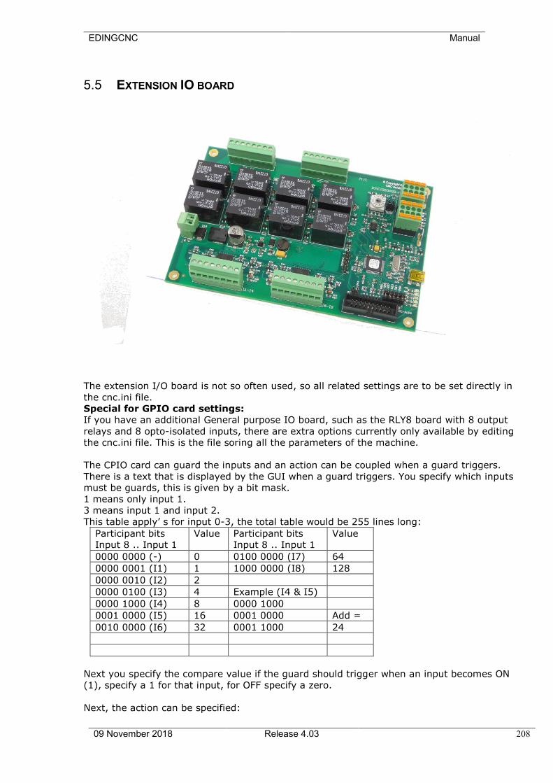
EDINGCNC Manual
09 November 2018 Release 4.03 208
5.5 EXTENSION IO BOARD
The extension I/O board is not so often used, so all related settings are to be set directly in
the cnc.ini file.
Special for GPIO card settings:
If you have an additional General purpose IO board, such as the RLY8 board with 8 output
relays and 8 opto-isolated inputs, there are extra options currently only available by editing
the cnc.ini file. This is the file soring all the parameters of the machine.
The CPIO card can guard the inputs and an action can be coupled when a guard triggers.
There is a text that is displayed by the GUI when a guard triggers. You specify which inputs
must be guards, this is given by a bit mask.
1 means only input 1.
3 means input 1 and input 2.
This table apply’ s for input 0-3, the total table would be 255 lines long:
Participant bits
Input 8 .. Input 1
Value Participant bits
Input 8 .. Input 1
Value
0000 0000 (-) 0 0100 0000 (I7) 64
0000 0001 (I1) 1 1000 0000 (I8) 128
0000 0010 (I2) 2
0000 0100 (I3) 4 Example (I4 & I5)
0000 1000 (I4) 8 0000 1000
0001 0000 (I5) 16 0001 0000 Add =
0010 0000 (I6) 32 0001 1000 24
Next you specify the compare value if the guard should trigger when an input becomes ON
(1), specify a 1 for that input, for OFF specify a zero.
Next, the action can be specified:
EDINGCNC Manual
09 November 2018 Release 4.03 209
0 = nothing.
1 = warning.
2 = smooth stop (with ramp down).
3 = quick stop (immediately, no ramp down, this may give position loss.
This is how it looks in the cnc.ini for 1 rule,
there are max 8 rules for the RLY8 card.
[GPIO_RULES]
;Give warning message when Oil pressure 1 or 2 is low
;Input 4 = 0000 1000, input 5 = 0001 0000 together 0001 1000
;So the value for participant bits is 8 + 16 = 24
;When one of the inputs becomes 1, we want a warning message
;So compare bits are also 24
;Action is 1, warning
card_1_rule_1_text = "---Warning Oil is pressure low---"
card_1_rule_1_inputParticipantBits = 24
card_1_rule_1_inputCompareBits = 24
card_1_rule_1_action = 1
;Give smooth stop when Vacuum is to low
;Input 1 = 0000 0001
;So the value for participant bits is 1
;When one of the inputs becomes 1, we want a smooth stop
;So compare bits are 1
;Action is 2, smooth stop
card_1_rule_2_text = "---Warning Vacuum is pressure low---"
card_1_rule_2_inputParticipantBits = 1
card_1_rule_2_inputCompareBits = 1
card_1_rule_2_action = 2
;Give ESTOP when the water pressure is low
;Input 2 = 0000 0010
;So the value for participant bits is 2
;When one of the inputs becomes 1, we want a smooth stop
;So compare bits are 1
;Action is 3, ESTOP
card_1_rule_3_text = "---Water pressure low---"
card_1_rule_3_inputParticipantBits = 2
card_1_rule_3_inputCompareBits = 2
card_1_rule_3_action = 3
What also can be specified is the name of the IO in or output for the GUI. It is also done
directly in the cnc.ini.
[GPIO_NAMES]
gp_output_101_name = "Oil pump on"
gp_output_102_name = "Water pump on"
gp_output_103_name = "Touch Probe down"
gp_output_104_name = "Touch Probe up"
gp_output_105_name = "Vacuum 1"
gp_output_106_name = "Vacuum 2"
gp_output_107_name = "Vacuum 3"
gp_output_108_name = "Vacuum 4"
gp_input_101_name = "Vacuum pressure low"
gp_input_102_name = "No water pressure"
gp_input_103_name = ""
gp_input_104_name = "Oil pressure 1 low"

EDINGCNC Manual
09 November 2018 Release 4.03 210
gp_input_105_name = "Oil pressure 2 low"
gp_input_106_name = ""
gp_input_107_name = ""
gp_input_108_name = ""
These are the IO’s for card 1, the IO’s for card 2 have numbers 201 etc. instead of 101,
card 3 has numbers 301.. etc.
If a name is not filled in, the GUI will show the number.
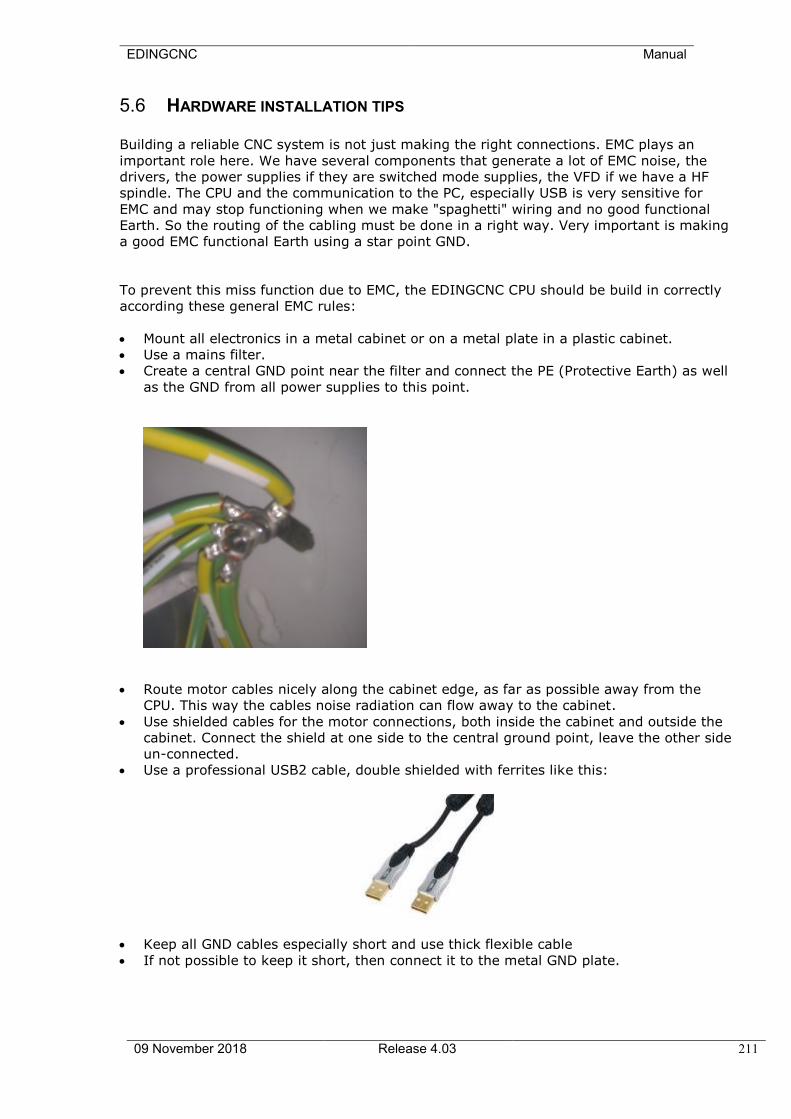
EDINGCNC Manual
09 November 2018 Release 4.03 211
5.6 HARDWARE INSTALLATION TIPS
Building a reliable CNC system is not just making the right connections. EMC plays an
important role here. We have several components that generate a lot of EMC noise, the
drivers, the power supplies if they are switched mode supplies, the VFD if we have a HF
spindle. The CPU and the communication to the PC, especially USB is very sensitive for
EMC and may stop functioning when we make "spaghetti" wiring and no good functional
Earth. So the routing of the cabling must be done in a right way. Very important is making
a good EMC functional Earth using a star point GND.
To prevent this miss function due to EMC, the EDINGCNC CPU should be build in correctly
according these general EMC rules:
• Mount all electronics in a metal cabinet or on a metal plate in a plastic cabinet.
• Use a mains filter.
• Create a central GND point near the filter and connect the PE (Protective Earth) as well
as the GND from all power supplies to this point.
• Route motor cables nicely along the cabinet edge, as far as possible away from the
CPU. This way the cables noise radiation can flow away to the cabinet.
• Use shielded cables for the motor connections, both inside the cabinet and outside the
cabinet. Connect the shield at one side to the central ground point, leave the other side
un-connected.
• Use a professional USB2 cable, double shielded with ferrites like this:
• Keep all GND cables especially short and use thick flexible cable
• If not possible to keep it short, then connect it to the metal GND plate.

EDINGCNC Manual
09 November 2018 Release 4.03 212
Schematic drawing of a possible good layout in the cabinet.
Here a picture of my own system, it contains various EMC problem makers, like 2 Switched
mode power supplies and a frequency inverter for a HF spindle. Check the routing of the
Motor and drive supply wires.
Also there a 4 stepper-motor drives working at 75 Volt, motor currents 4,2 Amp.
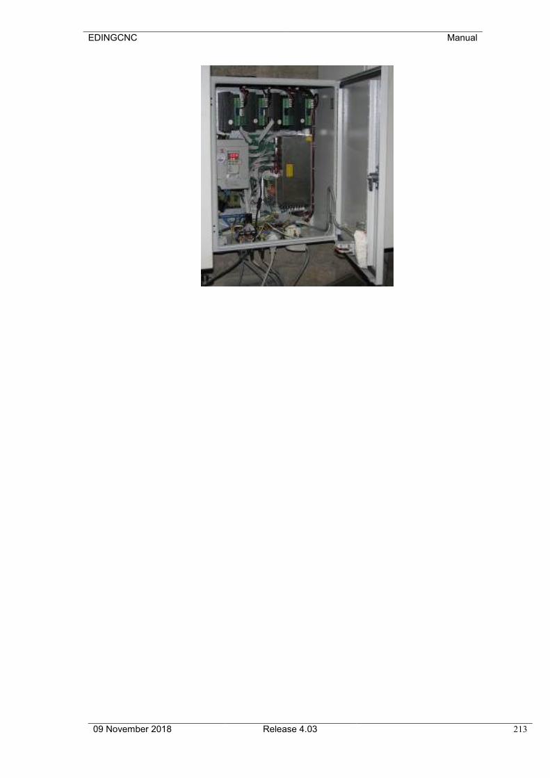
EDINGCNC Manual
09 November 2018 Release 4.03 213
EDINGCNC Manual
09 November 2018 Release 4.03 214
5.7 REFERENCES
[Albus] Albus, James S; et al; NIST Support to the Next Generation Controller Program:
1991 Final Technical Report; NISTIR 4888; National Institute of Standards and
Technology, Gaithersburg, MD; July 1992
[Allen-Bradley] Allen-Bradley; RS274/NGC for the Low End Controller; First Draft; Allen-Bradley;
August 1992
[EIA] Electronic Industries Association; EIA Standard EIA-274-D Interchangeable
Variable Block Data Format for Positioning, Contouring, and
Contouring/Positioning Numerically Controlled Machines; Electronic Industries
Association; Washington, DC; February 1979
[Fanuc] Fanuc Ltd.; Fanuc System 9-Model A Operators Manual; Pub B-52364E/03;
Fanuc Ltd; 1981
[Kramer1] Kramer, Thomas R.; Proctor, Frederick M.; Michaloski, John L.; The NIST
RS274/NGC Interpreter, Version 1; NISTIR 5416; National Institute of Standards
and Technology, Gaithersburg, MD; April 1994
[Kramer2] Kramer, Thomas R.; Proctor, Frederick M.; The NIST RS274KT Interpreter;
NISTIR 5738; National Institute of Standards and Technology, Gaithersburg, MD;
October 1995
[Kramer3] Kramer, Thomas R.; Proctor, Frederick M.; The NIST RS274/NGC Interpreter -
Version 2; NISTIR 5739; National Institute of Standards and Technology,
Gaithersburg, MD; October 1995
[Kramer4] Kramer, Thomas R.; Proctor, Frederick M.; The NIST RS274/VGER Interpreter;
NISTIR 5754; National Institute of Standards and Technology, Gaithersburg, MD;
November 1995
[K&T] Kearney and Trecker Co.; Part Programming and Operating Manual, KT/CNC
Control, Type C; Pub 687D; Kearney and Trecker Corp.; 1980
[NCMS] National Center for Manufacturing Sciences; The Next Generation Controller Part
Programming Functional Specification (RS-274/NGC); Draft; NCMS; August 1994
[Proctor] Proctor, Frederick M.; Kramer, Thomas R.; Michaloski, John L.; Canonical
Machining Commands; NISTIR 5970; National Institute of Standards and
Technology, Gaithersburg, MD; January 1997