edelbrock e-force supercharger2016-17 chevy camaro lt1 6.2l; manual transmission part #1559, 15590,...
TRANSCRIPT
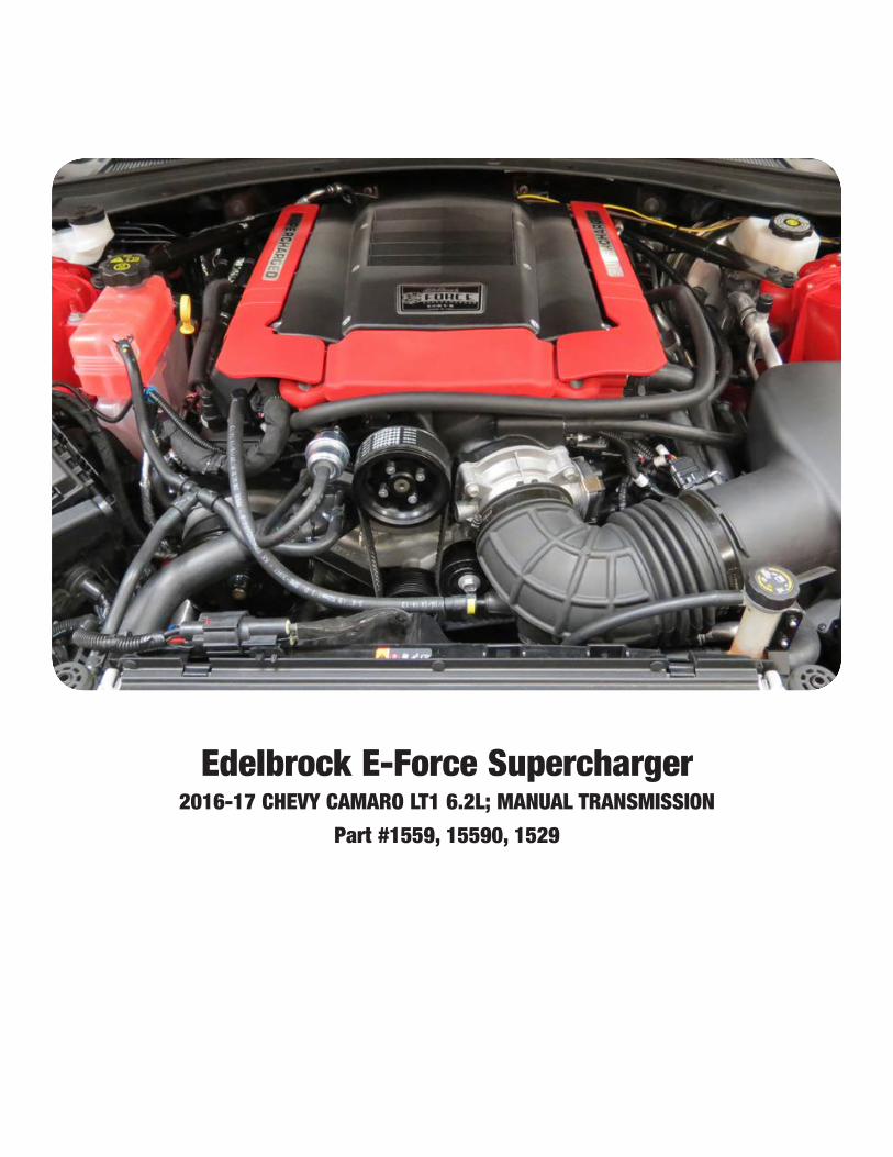
Edelbrock E-Force Supercharger2016-17 CHEVY CAMARO LT1 6.2L; MANUAL TRANSMISSION
Part #1559, 15590, 1529


WARNING!The supercharger bypass valve is factory installed and adjusted intended to be vacuum operated only. DO NOT move the solenoid actuator lever by hand or adjust the stop point. Moving the lever manually will damage the solenoid and the system will not function prop-erly. Damage to the bypass assembly from manual movement will not be covered under manufacture warranty.


IMPORTANT VEHICLE CALIBRATION DETAILS2017+ Vehicles ONLY
USA CUSTOMERS ONLY:In order to properly calibrate your vehicle for this supercharger kit, the ECM must be removed from the vehicle, packaged and shipped to Edelbrock. Your vehicles computer will be modified and or flashed for supercharger kit compatibility. Part numbers 1529, 15291, 15292, 15294, 15295, 15296 15297, 1519 and 15192 contain a box for shipping the ECM to Edelbrock (USA Custom-ers ONLY). (See ECM removal procedure on the following page.)
NOTE: Please email your Name, Address, phone number and email address to [email protected] and a prepaid return label will be sent. Affix the label to the package and drop it off at any UPS Store in your area.
This process will take up to five (5) business days from the time your vehicle’s computer is re-ceived. To avoid unplanned vehicle down time, we recommend that the computer be shipped out BEFORE beginning the supercharger installation.
INTERNATIONAL (NON-USA) CUSTOMERS PLEASE CALL EDELBROCK TECHNICAL SUP-PORT AT (800)-416-8628.

2017+ GM ECM Removal
The ECM on 2017 GM vehicles requires modification to support flash capability. Follow these instructions carefully to remove, package and ship the ECM to Edelbrock.
1. Disconnect the negative battery terminal and isolate the negative cable so it does not come in contact with the battery terminal or body of the vehicle.
2. Locate the ECM and remove the main harness connections. 3. Remove any hardware securing the ECM to its mounting location. 4. Fill out the provided ECM identification label with customer and vehicle
information and apply directly to the ECM. 5. Place the ECM in the provided box with packing material so the ECM cannot
move around in the box. Ship ECM to Edelbrock using the provided return shipping label.
IMPORTANT: The ECM is returned calibrated and ready for reinstallation. DO NOT attempt to load any other calibrations into the computer without consulting the Edelbrock calibration department.
After supercharger installation is complete, install the provided OBDII cap on the vehicle’s OBDII port to avoid accidental tampering by dealerships and other service centers.
Edelbrock E-Force Supercharger System 2016-17 Chevy Camaro LT1 6.2L
Installation Instructions


Edelbrock E-Force Supercharger System 2016-17 Chevy Camaro LT1 6.2L
Installation Instructions
Page 8©2017 Edelbrock LLCBrochure #63-1559
Rev. 11/2/17 - NP
E-MAIL EDELBROCK YOUR STOCK VEHICLE CALIBRATION AND VEHICLE INFORMATION
2016 VEHICLES ONLY: PLEASE COMPLETE THIS PROCEDURE PRIOR to starting the installation of your E-Force supercharger system. This will allow our calibration team to complete your calibration file while the installation of your supercharger system is being completed. Manufacturers regularly update the factory calibration, as a result, there is the possibility for delays due to not having access to your current calibration file. This can normally be resolved in 1 business day.
FAILURE TO PROVIDE ALL OF THE INFORMATION BELOW WILL DELAY THE COMPLETION OF THE CALIBRATION FILE FOR YOUR VEHICLE. TO LIMIT VEHICLE DOWN TIME, PLEASE SEND US THE REQUESTED INFORMATION BEFORE STARTING THE SUPERCHARGER INSTALL.
Please e-mail the requested information below to [email protected] with the E-mail Subject as “Calibration Update”. We will complete your calibration and e-mail it back to you as soon as possible. MOST calibration updates will be sent back the same business day. In rare cases, it could take up to 1-2 business days to complete. Please contact our Tech Hot Line at (800)416-8628 if you have any questions or if you need assistance with this procedure.
• Begin by downloading the SCT device updater software to your computer; it can be downloaded from: http://www.sctflash.com/software/SCTDeviceUpdater.exe.
• Put the vehicle into ACC mode but do not start the engine.
• Connect the supplied PCM cable from the programmer to the OBD-II connector.
• Select PROGRAM VEHICLE, use the arrow keys to highlight UPLOAD STOCK and press SELECT. Follow the prompts on the screen. NOTE: Use E92 for Engine Type and T43 or T43a (2014 Automatic Only) for Transmission Type.
• If the upload fails, you will be asked to AUTO DETECT. Press SELECT and follow the prompts on the screen. If the auto detect fails, please contact Edelbrock Tech Support @ 800-416-8628.
• Once the stock calibration has loaded to the handheld programmer, disconnect the programmer from the OBD-II connector and connect it to your PC using the supplied USB cable.
• Open the SCT software and select the button on the lower left hand side that reads GET STOCK FILE FROM DEVICE. Follow the instructions on the screen. NOTE: The stock calibration file will automatically be labeled using your VIN number followed by “.sul “ (XXXXXXXXXXXXX.sul)
• Once the download is complete, you can E-mail your stock vehicle calibration along with the vehicle information below to [email protected] or call 800-416-8628 and our Tech Support staff will assist you with E-mailing the file. NOTE: The subject line of your E-mail should read “Calibration Update”.
• Once we have the stock calibration file, along with the requested information below, we can update the calibration to work with your application. We will E-mail you the custom calibration which may be used until the release version of the calibration is available.
INFORMATION NEEDED:E-Mail Address:Vehicle Year:Vehicle Make:Vehicle Model (Specify if Z06, Z51, etc..):Engine Size:
Transmission:Fuel Octane (91 or 93 ONLY):Supercharger System Part Number:Supercharger Serial Number:Programmer Serial Number:

Edelbrock E-Force Supercharger System 2016-17 Chevy Camaro LT1 6.2L
Installation Instructions
Page 9©2017 Edelbrock LLCBrochure #63-1559
Rev. 11/2/17 - NP
Thank you for purchasing the Edelbrock Supercharger System for the Chevy Camaro LT1. The Edelbrock E-Force Supercharger System for the Chevy Camaro utilizes the same Eaton Gen VI TVS Supercharger rotors but housed inside a redesigned, low profile, supercharger manifold. The manifold is Edelbrock’s lowest profile supercharger manifold to date. Paired with short, bolt-on runners, this new package will fit under the factory hood with no modifications to the stock body or hood. The supercharger retains the inverted design which expels air upward. Air pressure then builds in the plenum, before being drawn down through the twin intercooler cores.
This system features a cast water crossover, a design that simplifies the intercooler hose routing. The water crossover is secured to the manifold, allowing the cooled 50/50 coolant mixture from the LTR (Low Temp Radiator) to cool down the twin intercoolers housed inside the manifold.
The supercharger is 50-State emissions legal (pending), and includes a 3-year 36,000 mile warranty so that there are no worries when installing it on a brand new car.
Installation time: Approximately 11 hours.
INTRODUCTION
TOOLS AND SUPPLIES REQUIRED
z Jack and Jack Stands OR Service Lift z Claw-Type Harmonic Balancer Puller z Harmonic Balancer Installation Tool z Ratchet and Socket Set including but not limited to: 7mm, 8mm, 10mm (standard, deep and swivel), 11mm, 12mm, 13mm, 15mm, 18mm, 21mm, 24mm
z Wrench Set including but not limited to: 8mm, 10mm, 15mm, 11/16”
z Breaker Bar: 1/2” z Compressed Air z Power Drill z Drill Bit: 1.75” Hole Saw z Torx Drives: T15, T30 z Panel Puller z Razor Blade
z Flat Blade & Phillips Screwdrivers z Coolant Drain Bucket z 50/50 Coolant Mixture z Side Cutters z 3/8” Fuel Line Removal Tools z Torque Wrench z Angle Meter z GM Flywheel Holding Tool z Pliers OR Hose Clamp Removal Tool z Blue, Green and Red Thread Retaining Compound z O-ring Lube z Masking Tape z Shop Rags z Non-Black Sharpie or equivalent z Wire Ties

Edelbrock E-Force Supercharger System 2016-17 Chevy Camaro LT1 6.2L
Installation Instructions
Page 10©2017 Edelbrock LLCBrochure #63-1559
Rev. 11/2/17 - NP
Due to the complexity of the Edelbrock E-Force Supercharging system, it is recommended that this system only be installed by a qualified professional with access to a service lift, pneumatic tools, and a strong familiarity with automotive service procedures. To qualify for the drivetrain warranty, it is necessary to have this system installed by a Certified ASE Technician at a licensed business, GM Dealership, or an Authorized Edelbrock Installer. Failure to do so will void and/or disqualify any and all optional supplemental warranties offered with this system. Please contact the Edelbrock Technical Support department if you have any questions regarding this system and/or how your installer of choice will affect any warranty coverage for which your vehicle may qualify.
Proper installation is the responsibility of the installer. Improper installation will void all manufacture’s standard warranties and may result in poor performance and engine or vehicle
damage.Inspect all components for damage that may have occurred in transit before beginning
installation. If any parts are missing or damaged, contact Edelbrock Technical Support, not your parts distributor.
Any equipment that directly modifies the fuel mixture or ignition timing of the engine can cause severe engine damage if used in conjunction with the Edelbrock E-Force Supercharger System. This includes, but is not limited to: OBDII programmers, MAF sensors, adapters and any other device that modifies signals to and/or from the ECU. Aftermarket bolt-on equipment such as underdrive pulleys or air intake kits will also conflict with the operation of the supercharger and must be removed prior to installation. Use of any of these products with the E-Force Supercharger could result in severe engine damage.
Any previously installed aftermarket tuning equipment must be removed and the vehicle returned to an as-stock condition before installing the supercharger.
Before beginning the installation, use the enclosed checklist to verify that all components are present in the box. Then inspect each component for damage that may have occurred in transit. If any parts are missing or damaged, contact Edelbrock Technical Support (800-416-8628), not your parts distributor.
WARNING: Installation of this supercharger will result in a significant change to the performance characteristics of your vehicle. It is highly recommended that you take some time to familiarize yourself with the added power and how it’s delivered. This must be done in a controlled environment. Take extra care on wet and slippery roads as the rear tires will be more likely to lose traction with the added power. It is never recommended to turn off your vehicles traction control system.
IMPORTANT WARNINGS

Edelbrock E-Force Supercharger System 2016-17 Chevy Camaro LT1 6.2L
Installation Instructions
Page 11©2017 Edelbrock LLCBrochure #63-1559
Rev. 11/2/17 - NP
It is recommended that you check the Edelbrock Tech Center Website for any updates to this installation manual. Please refer to the lower right hand corner to verify that you have the latest revision of this installation manual before beginning the installation.
Tech Center: http://www.edelbrock.com/automotive_new/misc/tech_center/install/index.php
91 octane or higher gasoline is required at all times. If your vehicle has been filled with anything less, it must be run until almost dry and refilled with 91 or higher octane gasoline twice prior to installation.
Any failures associated with not using premium 91 octane gasoline or higher, will be ineligible for warranty repairs.
IMPORTANT WARNINGS CONT’D
Edelbrock Authorized Installer DisclaimerAuthorized installers of Edelbrock products are independent companies over which Edelbrock has no right of control. Edelbrock LLC makes no claims regarding the abilities, expertise or competency of individual employees of any authorized installer. Each authorized installer is an independent company and makes its own independent judgments. Edelbrock LLC specifically disclaims any responsibility to any party including third parties for the actions, or the failure to act, of individuals, agents or a company authorized in the installation of Edelbrock LLC products.

Edelbrock E-Force Supercharger System 2016-17 Chevy Camaro LT1 6.2L
Installation Instructions
Page 12©2017 Edelbrock LLCBrochure #63-1559
Rev. 11/2/17 - NP
INSTALLATION HARDWARE IDENTIFICATION GUIDE (Parts Are Not To Scale)
BAG #2 - INTERCOOLER HARDWARE
Item P/N QTY. Description Torque Spec
1 36-1534 1 Bolt, Hex Flange, M6 X 25mm N/A
2 36-1507 2 Bolt, Hex Flange, M6 X 16mm N/A
3 36-1552 2 Bolt, Hex Flange, M6 X 10mm N/A
4 82-8720 2 Washer, 5/16 ID N/A
5 36-1541 2 M6 Lock Nut N/A
6 76-0150 1 Spacer, Plastic N/A
7 12-1590 1 Push Pin Tree N/A
8 46-2155 8 3/4” Hose Clamp N/A
BAG #3 - MANIFOLD / RUNNER HARDWARE
Item P/N QTY. Description Torque Spec
1 36-1573 14 Bolt, SHCS, M6 x 80mm 8 ft-lbs
2 36-4025 10 Bolt, Hex Flange, M6 x 55mm 8 ft-lbs
3 36-1575 2 Bolt, Hex Flange, M6 x 25mm 8 ft-lbs
BAG #1 - FEAD HARDWARE
Item P/N QTY. Description Torque Spec
1 36-1570 2 Bolt, Hex Flange, M10 x 100mm 32 ft-lbs
2 36-0159 2 Bolt, Hex Flange, M8 x 55mm 22 ft-lbs
3 36-1519 3 Bolt, Hex Flange, M8 x 40mm 22 ft-lbs

Edelbrock E-Force Supercharger System 2016-17 Chevy Camaro LT1 6.2L
Installation Instructions
Page 13©2017 Edelbrock LLCBrochure #63-1559
Rev. 11/2/17 - NP
BRACKET AND FEAD IDENTIFICATION GUIDE(Parts Are Not To Scale)
Item P/N QTY. Description
1 38-1608 1 Tensioner Bracket
2 38-1609 1 Tensioner, CTS-V
51-4233 1 Balancer / Damper (Not Pictured)
3 51-3992 1 Idler Pulley
4 51-3994 1 Idler Pulley
5 51-3993 1 Idler Pulley
6 38-0187 1 Horn Relocation Bracket
7 38-0129 1 Water Pump Bracket
8 51-4216 1 Bolt, Damper
9 38-0181 1 Surge Tank Bracket
⑧ ⑨

Edelbrock E-Force Supercharger System 2016-17 Chevy Camaro LT1 6.2L
Installation Instructions
Page 14©2017 Edelbrock LLCBrochure #63-1559
Rev. 11/2/17 - NP
HOSE IDENTIFICATION GUIDE(Parts Are Not To Scale)
Item P/N QTY. Description
1 22-15599 1 Air Intake Inlet PCV
2 56-1000 1 Hose Brake Booster
3 51-4255 1 Hose, Surge Tank to S/C
4 22-15598 1 Hose, Valley to Inlet
5 54-4256 1 Hose, S/C to LTR
6 51-4257 1 Hose, LTR to WP
7 51-4254 1 Hose, Surge Tank to WP

Edelbrock E-Force Supercharger System 2016-17 Chevy Camaro LT1 6.2L
Installation Instructions
Page 15©2017 Edelbrock LLCBrochure #63-1559
Rev. 11/2/17 - NP
HOSE ROUTING DIAGRAM
Heat Exchanger (LTR)
Water Pump
Surge Tank
Supercharger

Edelbrock E-Force Supercharger System 2016-17 Chevy Camaro LT1 6.2L
Installation Instructions
Page 16©2017 Edelbrock LLCBrochure #63-1559
Rev. 11/2/17 - NP
WIRE HARNESS GUIDE(Parts Are Not To Scale)
Constant +12v Power Wire
EVAP Engine Harness
TMAP Sensor
FuseRelay
Ground Strap
Intercooler Water Pump
MAF Sensor Engine Harness
MAP Sensor Engine Harness
EVAP Solenoid
MAF Sensor
TMAP HARNESS
WATER PUMP HARNESS

©2017 Edelbrock LLCBrochure #63-1559
Rev. 11/2/17 - NP
Edelbrock E-Force Supercharger System 2016-17 Chevy Camaro LT1 6.2L
Installation Instructions
Page 17
SUPERCHARGER INSTALLATIONSteps 1-13 are for 2016 vehicles only. 2017+ vehicles only need to reinstall the ECM upon being returned from Edelbrock. The computer has already been recalibrated for this supercharger system. After the computer is reinstalled, secure the provided OBDII “DO NOT FLASH” cover onto the OBDII port.
WARNING: Battery must be sufficiently charged before starting the PCM flashing procedure.
Only begin the PCM flashing procedure when you have downloaded the calibration file from the Edelbrock Calibration Team to the handheld programmer. Do not flash the PCM until you are ready to install the supercharger. Once the PCM is flashed, DO NOT START the engine until the installation of the E-Force supercharger is complete.
1. Put the car into ACC mode, but don’t start the vehicle.
2. Connect the supplied PCM cable on the handheld programmer to the OBD-II connector located below the steering wheel, and to the left of your knee.
3. Use the directional pad to highlight the Program Vehicle option and press the Select button.
4. Use the directional pad to highlight the Pre-programmed Tune option and press the Select button.
5. Read the disclaimer then press Select to continue.
6. Verify that the ignition is in the ‘Key On’ position and that the engine is not running, then press Select.
7. Use the directional pad to highlight your vehicle and transmission combination then press Select.
8. Use the directional pad to highlight the Begin Program
option then press Select.
9. Depending on your specific drivetrain configuration, several separate operations may take place during this step. Completion of each operation will cause the progress bar to reset to zero.
10. DO NOT unplug the programmer until prompted.
11. Turn the vehicle off when prompted to do so by the handheld programmer.
12. Read the parting message from programmer then press Select to continue.
13. Unplug the programmer cable from the OBD-II port. This concludes the PCM flashing procedure. DO NOT start the engine until the supercharger installation is complete.
14. Open the trunk and access the battery via the door on the passenger side trunk liner. Using a 10mm socket, disconnect the negative battery terminal.

©2017 Edelbrock LLCBrochure #63-1559
Rev. 11/2/17 - NP
Edelbrock E-Force Supercharger System 2016-17 Chevy Camaro LT1 6.2L
Installation Instructions
Page 18
15. Using a T-15 Torx driver, remove ten (10) screws securing the top of the fascia. Using a 10mm socket, remove four bolts securing the radiator shroud. NOTE: there’s two small plastic spacers that can fall out when the bolts are removed. It should be carefully removed and set aside to be re-installed later.
16. Using a 7mm socket, remove the bolts securing the bottom of the fascia.
NOTE: Although not required, removal of the front wheels will simplify the following procedures.
17. Use a T-15 Torx drive to remove six (6) screws securing the sides of the fascia; three (3) per side.
18. Use a 7mm socket to remove six (6) screws securing the corner of the fascia to the fender; three (3) per side.
19. Pull back the wheel liner and remove eight (8) additional screws securing the fascia to the fender; four (4) per side. NOTE: Fourth bolt not shown, location is above top bolt.

©2017 Edelbrock LLCBrochure #63-1559
Rev. 11/2/17 - NP
Edelbrock E-Force Supercharger System 2016-17 Chevy Camaro LT1 6.2L
Installation Instructions
Page 19
20. Disconnect any necessary lamp and sensor harnesses and carefully remove the fascia.
21. Drain the coolant by removing the petcock on the lower driver side of the radiator.
22. Carefully remove the factory manifold side covers.
23. Remove the fresh air PCV hose attached to the inlet elbow.
24. Using a hose clamp tool, remove the noise generator hose from the inlet elbow. Loosen the warm clamps securing the inlet elbow and remove the elbow.
25. Remove the driver side PCV hose.
26. Using a 10mm socket, remove the nut securing the noise generator to the firewall.
27. Remove the noise generator assembly as it will not be reused.
28. Disconnect the electronic throttle body connector from the throttle body.

©2017 Edelbrock LLCBrochure #63-1559
Rev. 11/2/17 - NP
Edelbrock E-Force Supercharger System 2016-17 Chevy Camaro LT1 6.2L
Installation Instructions
Page 20
29. Unclip the fuel line from the top of the manifold.
30. Using a deep 10mm socket, remove four (4) bolts securing the manifold cover.
31. Remove the valley to manifold PCV hose.
32. Remove the EVAP line from the hardline located on the firewall and from the EVAP solenoid.
33. Disconnect the brake booster line assembly from the junction on the driver side strut tower.
34. Unplug the MAP connector from the MAP sensor.
35. Using a 10mm socket, remove ten (10) bolts securing the intake manifold to the cylinder heads. Carefully remove the intake manifold assembly.

©2017 Edelbrock LLCBrochure #63-1559
Rev. 11/2/17 - NP
Edelbrock E-Force Supercharger System 2016-17 Chevy Camaro LT1 6.2L
Installation Instructions
Page 21
36. Clean the intake port surfaces with a shop rag. Cover the ports with protective tape to keep out debris. Remove the black foam insulator from the valley and set aside.
37. Install the supplied grommet onto the firewall where the noise generator was removed.
38. Remove the retaining clip on the fuel feed line. Using a 3/8” fuel line tool, disconnect the fuel line from the fuel line extension and from the factory hardline. CAUTION: Place a shop rag around the fuel line to prevent fuel from spraying.
39. Using a 10mm socket, remove the bolt securing the fuel line extension to the valve cover. Remove the retaining clip on the fuel line extension. Then remove the fuel line extension from the fuel pump using a 3/8” fuel line tool.
40. Install the supplied fuel line extension onto the fuel pump barb.
41. Loosely secure the fuel line extension to the valve cover using the factory bolt. Apply Blue thread locker to the threads of the fuel line extension lock nut. Using a 11/16” wrench, secure the fuel line extension to the fuel pump using the lock nut. Tighten the lock nut, DO NOT OVER TIGHTEN. Securely fasten the fuel line extension support bracket to the valve cover using the factory bolt.
42. Using a razor blade or equivalent, cut out the fuel line relief on the foam valley insulator.

©2017 Edelbrock LLCBrochure #63-1559
Rev. 11/2/17 - NP
Edelbrock E-Force Supercharger System 2016-17 Chevy Camaro LT1 6.2L
Installation Instructions
Page 22
43. Reinstall the foam valley insulator onto the valley making sure it is seated properly.
44. Remove the rubber side cover grommets from the factory side covers. Using a little lube, install the rubber grommets onto the supplied side cover brackets.
45. Using a Torx T30, remove the driver side coil cover. Using a 10mm socket, remove the 2nd and 3rd bolt from the driver side valve cover.
46. Re-install the bolts removed from the previous step with the side cover brackets as shown.
47. Using a Torx T30, loosen the passenger side coil cover and remove the 2nd and 4th valve cover bolts with a 10mm socket. Secure the side cover brackets to the valve cover with the stock valve cover bolts.
48. Using wire ties, secure both left and right engine harness bundles to the ignition coil bolt bosses. This will prevent the side covers from coming loose once installed.
49. Using a stretchy belt removal/installer tool, remove the belt from the A/C compressor and the damper.
NOTE: Steps 50-56 will highlight the procedure to remove the electric cooling fan as required to install the supplied damper.
50. Use a 10mm socket to remove the three (3) bolts securing the bottom of the fan shroud.

©2017 Edelbrock LLCBrochure #63-1559
Rev. 11/2/17 - NP
Edelbrock E-Force Supercharger System 2016-17 Chevy Camaro LT1 6.2L
Installation Instructions
Page 23
51. Disconnect the electric fan connector. Use a panel puller to detach the harness tree-clip from the fan shroud.
52. Using a hose clamp removal tool, remove the upper radiator hose and the overflow hose from the radiator.
53. Using a hose clamp removal tool, detach the lower passenger side radiator hose. NOTE: The clamp may not come off because of adhesive. Simply compress the clamp and pull the hose simultaneously.
54. Remove the retaining clip securing the transmission cooler line to the radiator and remove the transmission cooler line. NOTE: Be extremely cautious not to drop or lose this clip. Keep the clip in a safe place to be re-installed later.
55. Using a panel puller, remove the coolant lines from the fan shroud.
56. Remove four (4) bolts securing the electric fan to the radiator using a 10mm socket. Carefully remove the electric fan assembly.
NOTE: Steps 57-65 will highlight the steps required to remove the starter to install the GM flywheel holding tool.
57. Using a hose clamp tool, disconnect the overflow hose and the feed hose from the coolant reservoir.

©2017 Edelbrock LLCBrochure #63-1559
Rev. 11/2/17 - NP
Edelbrock E-Force Supercharger System 2016-17 Chevy Camaro LT1 6.2L
Installation Instructions
Page 24
58. Using a deep 10mm socket, remove three (3) nuts securing the coolant reservoir tank. Remove reservoir and set aside.
59. Using a panel puller, remove the engine harness from the support bracket located on the passenger side valve cover.
60. Using a 10mm socket, remove the engine harness support bracket.
61. Disconnect the passenger side spark plug wires from the coil packs.
62. Remove the two nuts securing the passenger exhaust manifold to the lower exhaust pipe.
63. Remove the bolt securing the oil dip stick using a 10mm socket.
64. Remove five (5) bolts securing the passenger side exhaust manifold to the cylinder head. Carefully remove the exhaust manifold along with the dipstick. Discard the exhaust manifold gasket.
65. Remove the starter and heat shield to install a GM flywheel holding tool.
66. Using a 24mm socket and a breaker bar, remove the factory harmonic balancer bolt. Do not discard the bolt at this time as it will be temporarily used during the installation procedure.
67. Remove the factory harmonic balancer using a Claw-Type Damper Puller.

©2017 Edelbrock LLCBrochure #63-1559
Rev. 11/2/17 - NP
Edelbrock E-Force Supercharger System 2016-17 Chevy Camaro LT1 6.2L
Installation Instructions
Page 25
68. Apply white grease to the snout of the crank and to the inside of the balancer hub. Apply clean engine oil to the outside of the balancer hub.
69. Line up the key on the crank with the key way on the harmonic balancer. Install the supplied harmonic balancer using an appropriate harmonic balancer installation tool. NOTE: The balancer should be positioned onto the end of the crankshaft as straight as possible prior to tool installation.
70. Using a 24mm socket and a torque wrench, install the used factory balancer bolt and torque it to 240 ft-lbs. Then remove the factory balancer bolt and discard.
NOTE: The nose of the crankshaft should be recessed 8mm (.31”in) into the balancer bore. Measure for a correctly installed balancer. If the balancer is not installed to the proper dimensions, repeat the installation procedure until the proper dimensions are achieved.
71. Using a 24mm socket and a torque wrench, install the new supplied balancer bolt and torque it to 110 ft-lbs. Loosen the bolt 360° and re-torque the bolt to 59 ft-lbs. + an additional 125° of rotation.
72. Remove the flywheel holding tool and reinstall the starter, heat shield and plastic transmission cover.
73. Reinstall the exhaust manifold and dipstick using the supplied exhaust manifold gasket.
74. Reinstall the exhaust, spark plug wires, and engine harness bracket.
75. Reinstall the coolant reservoir tank, the electric fan assembly and the radiator hoses.
76. Using a stretchy belt removal/installation tool, install the factory stretchy belt onto the new damper and the A/C compressor. NOTE: Be careful not to damage the belt. Inspect the belt for any damage after the installation.
77. Install the factory accessory drive belt using the routing diagram below.
78. Using a 3/4” hose clamp from hardware Bag #2, secure the WP to Surge Tank hose to the water pump noting the orientation of the hose.

©2017 Edelbrock LLCBrochure #63-1559
Rev. 11/2/17 - NP
Edelbrock E-Force Supercharger System 2016-17 Chevy Camaro LT1 6.2L
Installation Instructions
Page 26
79. Install the supplied water pump isolator onto the water pump noting the orientation.
80. Remove the two (2) chassis bolts adjacent to the radiator assembly. TIP: A secondary wrench may be required to hold the nut located inside the chassis frame.
81. Using the washers from hardware Bag #2 and the factory chassis bolts, mount the supplied water pump bracket to the frame in the location where the chassis bolts were removed. Install the water pump assembly onto the water pump bracket. TIP: A secondary wrench may be required to hold the nut located inside the chassis frame.
82. Using a 10mm socket, remove the ground strap from the engine block. Location is directly above the A/C compressor.

©2017 Edelbrock LLCBrochure #63-1559
Rev. 11/2/17 - NP
Edelbrock E-Force Supercharger System 2016-17 Chevy Camaro LT1 6.2L
Installation Instructions
Page 27
83. Disconnect the engine harness located on the front of the driver side cylinder head. Using a 10mm socket remove the bolt securing the harness to the head.
84. Position the ground strap behind the engine harness bracket and secure the engine harness to the cylinder head. Reconnect the engine harness.
85. Install the supplied tensioner bracket to the provisions on the cylinder head and engine block using two (2) M10 x 100mm bolts and two (2) M8 x 55mm bolts supplied in hardware Bag #1. Torque M10 bolts to 32 ft-lbs and M8 bolts 22 ft-lbs.
86. Install the supplied tensioner onto the FEAD bracket using three (3) M8 x 40mm bolts from hardware bag #1. Torque bolts to 22 ft-lbs.
87. Install the larger grooved idler pulley to the FEAD bracket. Torque bolt to 22 ft-lbs.
88. Install the smooth idler pulley to the upper water pump provision and the smaller grooved idler to the lower water pump provision. Torque both bolts to 22 ft-lbs.

©2017 Edelbrock LLCBrochure #63-1559
Rev. 11/2/17 - NP
Edelbrock E-Force Supercharger System 2016-17 Chevy Camaro LT1 6.2L
Installation Instructions
Page 28
89. Position the EVAP hardline in front of the fuel hardline. Split the supplied foam tube down the middle with a razor and secure it to the EVAP hardline with wire ties.
EVAP
90. Connect the supplied fuel feed line to the hardline on the firewall and route it over towards the fuel adapter line. Secure the fuel line to the brake line with wire ties.
91. Using a razor, remove the 45° quick connect fitting from the factory valley to manifold PCV hose. Install the quick connect fitting to the supplied Valley to Inlet hose assembly.
92. Install the 45° end of the Valley to Inlet hose assembly onto the valley provision.
93. Remove the factory O-ring gaskets from the intake manifold.
94. Clean and inspect the O-ring gaskets. Replace torn or damage O-rings as needed. Using a razor blade remove the tips off all eight (8) factory O-ring gaskets.
95. Install four (4) modified O-ring gaskets onto the passenger side E-Force runner. NOTE: Driver side runner will have a slot for the fuel line, the passenger side runner will not.

©2017 Edelbrock LLCBrochure #63-1559
Rev. 11/2/17 - NP
Edelbrock E-Force Supercharger System 2016-17 Chevy Camaro LT1 6.2L
Installation Instructions
Page 29
96. Remove the protective tape from the cylinder head ports. Install the passenger side runner onto the cylinder head using the dowel pins for alignment. Apply Blue thread locker to the threads of five (5) M6 x 55mm Hex bolts from Bag #3. Using a 10mm socket, install the bolts using the torque sequence below. Torque bolts to 4 ft-lbs. and then to 8 ft-lbs.
� � � ��
97. Repeat for the driver side runner. NOTE: Verify that the previously installed fuel line extension clears the runner. Reposition the fuel line bracket as needed.
98. Connect the supplied 1/4” hose to the actuator barb on the driver side runner. Route the hose over towards the passenger side runner and towards the front of the vehicle. TIP: Make sure to tuck the hose along the bottom of the passenger side runner as to clear the supercharger manifold.
99. Connect the TMAP harness to the TMAP sensor located on the inside of the passenger side runner. Route the harness towards the front of the vehicle, along the valley side of the driver side runner.
100. The MAP connector will route behind the driver side runner and connect to the factory MAP connector. NOTE: Some factory MAP connectors will have a inner left tab which will have to be trimmed. The two MAF connectors on the TMAP harness will connect to the MAF sensor and the factory MAF connect later.
101. Install the supplied Manifold to Runner gaskets onto the runners. Note that the passenger side gasket will be longer than the driver side gasket. TIP: You can use a dab of The Right Stuff gasket maker to help hold the gasket in place while installing the manifold.
102. With help from an assistant, carefully lower the supercharger manifold onto the runners. CAUTION: Verify that the runner gaskets are properly aligned before proceeding.

©2017 Edelbrock LLCBrochure #63-1559
Rev. 11/2/17 - NP
Edelbrock E-Force Supercharger System 2016-17 Chevy Camaro LT1 6.2L
Installation Instructions
Page 30
103. Apply Blue thread locker to the fourteen (14) M6 x 80mm SHCS bolts and two (2) M6 x 25mm Hex bolts from Bag #3. Place the bolts into their provisions noting that location 13 and 16 will use the M6 x25mm bolts. Using a 5mm Hex drive and a 10mm socket, secure the manifold to the engine using the torque sequence below. Torque bolts to 4 ft-lbs. and then to 8 ft-lbs.
1
23
4
5
6
7
8
9
1011
12
13
14
15
16
FRONTM6 x 25mm
104. Connect the Valley to Inlet hose to the manifold inlet.
105. Using a breaker bar, rotate the tensioner counterclockwise and install the supercharger belt using the routing diagram below.
106. Using a 10mm socket, remove four (4) bolts securing the throttle body to the factory manifold.
107. Using the factory O-ring gasket and the factory bolts, secure the throttle body to the supercharger inlet. Reconnect the electronic throttle body connector to the throttle body.
108. Using a 10mm socket, remove th e EVAP solenoid from the stock manifold. Inspect the o-ring gasket and replace if needed.

©2017 Edelbrock LLCBrochure #63-1559
Rev. 11/2/17 - NP
Edelbrock E-Force Supercharger System 2016-17 Chevy Camaro LT1 6.2L
Installation Instructions
Page 31
109. Apply o-ring lube to the o-ring on the EVAP solenoid and install onto the supercharger manifold using the factory EVAP solenoid bolt.
110. Attach the previously installed actuator hose to the actuator.
111. Using a 10mm socket, remove the hood latch assembly and the crash beam support braces.
112. Disconnect and remove the horn assembly from the crash beam using a 10mm socket. Using a panel puller, remove the push pins securing the wire harness to the crash beam as well as the radiator shrouds.
HORN
113. Using a 10mm wrench and a 13mm socket, remove ten (10) bolts, five (5) per side, securing the crash beam to the chassis.
10mm
114. Using a panel puller, remove two (2) push pins securing the driver side radiator shroud to the radiator and one securing the rubber shroud. Remove both shrouds.

©2017 Edelbrock LLCBrochure #63-1559
Rev. 11/2/17 - NP
Edelbrock E-Force Supercharger System 2016-17 Chevy Camaro LT1 6.2L
Installation Instructions
Page 32
115. Using a 1.75” hole saw, drill a hole into the center of the upper portion of the shroud. Using a cutting tool, remove some material from the center of the shroud opening as shown.
116. Reposition the shroud, and secure using the factory upper and vertical push pins.
117. Using a panel puller, remove the lower push pin from the passenger side radiator shroud.
118. Using a panel puller, remove both inner push pins securing the right and left air ducts.
119. Cut the supplied foam tape in half and line the rear side tanks of the supplied LTR as shown. TIP: Inlet barbs will point towards the front of the vehicle.
120. Position the LTR in front of the radiator assembly with the inlet barbs positioned on the driver side of the vehicle. Using the supplied push pins from hardware Bag# 2, secure the LTR to the radiator shrouds.
121. Secure the lower portion of the LTR to the air ducts using two (2) M6 x 16mm bolts and two (2) M6 locknuts from hardware Bag #2.

©2017 Edelbrock LLCBrochure #63-1559
Rev. 11/2/17 - NP
Edelbrock E-Force Supercharger System 2016-17 Chevy Camaro LT1 6.2L
Installation Instructions
Page 33
122. Remove the upper driver side radiator fan bolt. Using the M6 x 25mm bolt and spacer from hardware Bag #2, secure the surge tank bracket to the upper driver side radiator fan mount. Secure the surge tank to the surge tank bracket with two (2) M6 x 10mm bolts.
Spacer
123. Using a 3/4” hose clamp from Bag #2, secure the LTR to Water Pump hose to the bottom LTR barb. Route the hose through the center opening of the radiator shroud.
124. Using a 3/4” hose clamp from Bag #2, secure the LTR to Water Pump hose to the outlet barb of the water pump.
125. Route the LTR to Manifold hose through the hole in the radiator shroud and back towards the manifold. Using a 3/4” hose clamp from Bag #2, secure the hose to the upper barb of the LTR.
126. Using a 3/4” hose clamp from Bag #2, secure the hose to the lower water crossover barb.
127. Using two (2) 3/4” hose clamps from hardware Bag #2, secure the Surge Tank to Manifold hose to the surge tank and upper water cross over barb.

©2017 Edelbrock LLCBrochure #63-1559
Rev. 11/2/17 - NP
Edelbrock E-Force Supercharger System 2016-17 Chevy Camaro LT1 6.2L
Installation Instructions
Page 34
128. Using a 3/4” hose clamp from hardware bag #2, secure the Water Pump to Surge Tank hose to the surge tank.
129. Reinstall the crash beam, support beams and the hood latch assembly.
130. Using a M6 x 16mm bolt from hardware Bag #2, secure the horn assembly to the supplied horn relocator bracket.
131. Install the horn assembly in the factory location using the factory bolt. Reconnect the horn connectors.
132. Reattach the harness to the crash beam and reinstall the front fascia reversing the disassembly procedure.
133. Using a razor, remove the longer hose from the check valve on the brake booster to manifold hose. Install the supplied 3/8” brake booster hose onto the check valve.
Factory
Supplied 3/8” Hose
134. Connect the quick connector on the brake booster hose assembly to the junction on the driver side strut tower. Connect the other end of the hose onto the barb on the supercharger inlet.
135. Connect the supplied EVAP hose to the hardline on the firewall. Route the hose over towards the driver side strut tower and connect it to the EVAP solenoid.
©2017 Edelbrock LLCBrochure #63-1559
Rev. 11/2/17 - NP
Edelbrock E-Force Supercharger System 2016-17 Chevy Camaro LT1 6.2L
Installation Instructions
Page 35
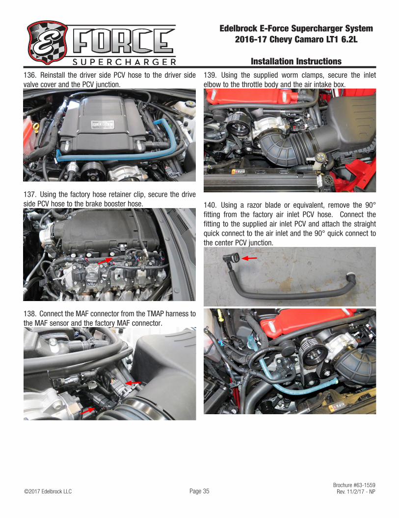
136. Reinstall the driver side PCV hose to the driver side valve cover and the PCV junction.
137. Using the factory hose retainer clip, secure the drive side PCV hose to the brake booster hose.
138. Connect the MAF connector from the TMAP harness to the MAF sensor and the factory MAF connector.
139. Using the supplied worm clamps, secure the inlet elbow to the throttle body and the air intake box.
140. Using a razor blade or equivalent, remove the 90° fitting from the factory air inlet PCV hose. Connect the fitting to the supplied air inlet PCV and attach the straight quick connect to the air inlet and the 90° quick connect to the center PCV junction.

©2017 Edelbrock LLCBrochure #63-1559
Rev. 11/2/17 - NP
Edelbrock E-Force Supercharger System 2016-17 Chevy Camaro LT1 6.2L
Installation Instructions
Page 36
141. Connect the POWER terminal on the water pump harness to the power junction on the fuse box.
142. Remove the factory GROUND terminal nut attached to the chassis. Attached the GROUND connector on the water pump harness to the chassis ground and secure with the factory terminal nut. Remove the nuts securing the fuse box to the chassis. Gently remove the fuse box from the mounting studs and secure the relay to the mounting stud. Reinstall fuse box nuts.
143. Route the EVAP connects over towards the EVAP solenoid. Connect the factory EVAP connector to the EVAP connector on the water pump harness. Connect the EVAP connector on the water pump harness to the EVAP solenoid. TIP: Note connector orientation.
144. Route the water pump connector over and down towards water pump and connect to the water pump.
145. Secure water pump harness to existing harnesses.
146. Fill the radiator reservoir tank with GM recommended 50/50 coolant blend.
147. Fill the supercharger surge tank with a 50/50 coolant and water mixture. NOTE: Please see “How to Prime the Edelbrock E-Force Intercooler Systems” at the end of these instructions for detailed instructions.
148. Reconnect the battery and switch ignition to the ON position, DO NOT START. With the ignition switch on, check for any coolant or fuel leaks. Repair all leaks before proceeding.
149. Install the supplied support barbs through the supplied support brackets and screw the support barbs onto the two (2) side covers with an 11mm socket.

©2017 Edelbrock LLCBrochure #63-1559
Rev. 11/2/17 - NP
Edelbrock E-Force Supercharger System 2016-17 Chevy Camaro LT1 6.2L
Installation Instructions
Page 37
150. Using a pair of scissors, cut the supplied strip of foam tape into 4 different lengths. Cut two (2) pieces 1 1/2” long, cut one (1) piece 14 1/4” long, and cut one (1) piece 12” long.
151. Adhere the 14 1/4” strip of foam tape to the top edge of the passenger side valve cover, adhere the 12” strip of foam tape to the top edge of the driver side valve cover, and adhere the two (2) 1 1/2” strips of foam tape on the Left and Right edge of the water crossover where the side covers make contact.
152. Install the side covers onto the side cover brackets.
Congratulations on the successful installation of your new Edelbrock E-Force Supercharger System. If you have any questions, please call our Technical Support hotline at 800-416-8628 and one of our technicians will be happy to assist you.

How to Prime the Edelbrock E-Force Intercooler Systems.
The electric water pump used on this Edelbrock E-Force Supercharger System has a built-in micro-processor that will vary pump cycle speed when air bubbles are present in the system. If a significant amount of air is trapped in the system, the pump may cycle at a slower speed and pulsations are likely to occur resulting in poor cooling performance.
For the best result, it is highly recommended to use a Radiator Cooling System Vacuum Purge and Refill Kit to properly evacuate the air from the intercooler system before filling with a 50/50 mixture of coolant and distilled water. If one is not available, the following procedure will be adequate.
1. Using the Lisle 24680 Spill-Free Funnel, or equivalent, secure the appropriate filler neck adapter to the surge tank.
2. Attach the funnel and fill with a 50/50 mixture of coolant and distilled water until the funnel is half full.
3. Turn the ignition to the ON position and listen for the pump’s electric motor to cycle. Air bubbles will begin to purge from the system as the coolant level drops. Add coolant to the funnel as necessary. NOTE: Do NOT let the coolant level in the funnel run empty as this may introduce air into the system.
4. To build more pressure in the intercooler system, try squeezing the intercooler hoses while the pump is cycling. Building pressure in the system will help purge the trapped air from the intercooler system.
5. Cycle the ignition OFF and wait a few seconds for the pump to come to a stop.
6. Cycle the ignition ON again and repeat until the sound of the electric pump is continuous without any pulsation. NOTE: During water pump start-up, it is normal for a slight pulsation to occur. Once the pump has reached its maximum cycle speed, no pulsations should be present.
7. Periodically inspect the water pump flow after a few drive cycles and re-fill the intercooler system as necessary.
8. Several drive cycles may be required to completely purge the air from the intercooler system. During a drive cycle, the intercooler system will build up pressure as the supercharger temperature increases. Any residual air trapped in the system will gradually bleed out of the surge tank as the system reaches a pressure above 5psi.
WARNING: Always avoid removing the surge tank cap when the engine is hot. The hot coolant is under pressure and may spray out causing burns.