ecss--e--10--05a - mil-std-188everyspec.com/esa/download.php?spec=ecss-e-10-05a.014990.pdf · ecss...
TRANSCRIPT

FOR SPACE STANDARDIZATION
EUROPEAN COOPERATION
ECSS
Space engineering
Functional analysis
ECSS SecretariatESA--ESTEC
Requirements & Standards DivisionNoordwijk, The Netherlands
ECSS--E--10--05A
13 April 1999
Downloaded from http://www.everyspec.com

ECSS13 April 1999ECSS--E--10--05A
2
Published by: ESA Publications DivisionESTEC, P.O. Box 299,2200 AG Noordwijk,The Netherlands
ISSN: 1028--396X
Price: DFl 35
Printed in The Netherlands
Copyright 1999 E by the European Space Agency for the members of ECSS
Downloaded from http://www.everyspec.com

ECSS 13 April 1999
ECSS--E--10--05A
3
Foreword
This Standard is one of the series of ECSS Standards intended to be applied to-gether for themanagement, engineering and product assurance in space projectsand applications. ECSS is a cooperative effort of the European Space Agency,National Space Agencies and European industry associations for the purpose ofdeveloping and maintaining common standards.
Requirements in thisStandardaredefined in termsofwhatshallbeaccomplished,rather than in terms of how to organize and perform the necessary work. This al-lows existing organizational structures andmethods to be appliedwhere they areeffective, and for the structures and methods to evolve as necessary without re-writing the standards.
The formulation of this Standard takes into account the existing ISO 9000 familyof documents.
ThisStandardhasbeen preparedby theECSSWorkingGroupE--10--05, reviewedby the ECSS Technical Panel and approved by the ECSS Steering Board.
Downloaded from http://www.everyspec.com

ECSS13 April 1999ECSS--E--10--05A
4
(This page is intentionally left blank)
Downloaded from http://www.everyspec.com
ECSS 13 April 1999
ECSS--E--10--05A
5
Contents list
Foreword 3. . . . . . . . . . . . . . . . . . . . . . . . . . . . . . . . . . . . . . . . . . . . . . . . . . . . . . . . .
1 Scope 7. . . . . . . . . . . . . . . . . . . . . . . . . . . . . . . . . . . . . . . . . . . . . . . . . . . . . . . .
2 Normative references 9. . . . . . . . . . . . . . . . . . . . . . . . . . . . . . . . . . . . . . . . .
3 Terms, definitions and abbreviated terms 11. . . . . . . . . . . . . . . . . . . . . . .
3.1 Terms and definitions 11. . . . . . . . . . . . . . . . . . . . . . . . . . . . . . . . . . . . . . . . . . . . . . .
3.2 Abbreviated terms 12. . . . . . . . . . . . . . . . . . . . . . . . . . . . . . . . . . . . . . . . . . . . . . . . .
4 Principles and methods of functional analysis 13. . . . . . . . . . . . . . . . . .
4.1 Principles 13. . . . . . . . . . . . . . . . . . . . . . . . . . . . . . . . . . . . . . . . . . . . . . . . . . . . . . . . .
4.2 Methods 13. . . . . . . . . . . . . . . . . . . . . . . . . . . . . . . . . . . . . . . . . . . . . . . . . . . . . . . . . .
4.3 Objectives 14. . . . . . . . . . . . . . . . . . . . . . . . . . . . . . . . . . . . . . . . . . . . . . . . . . . . . . . .
4.4 Logic and implementation overview 14. . . . . . . . . . . . . . . . . . . . . . . . . . . . . . . . .
4.5 Process 16. . . . . . . . . . . . . . . . . . . . . . . . . . . . . . . . . . . . . . . . . . . . . . . . . . . . . . . . . . .
4.6 Representation of the system 17. . . . . . . . . . . . . . . . . . . . . . . . . . . . . . . . . . . . . . . .
4.7 Functional analysis and engineering disciplines 24. . . . . . . . . . . . . . . . . . . . . . . .
4.8 Functional analysis and other disciplines 26. . . . . . . . . . . . . . . . . . . . . . . . . . . . . .
Downloaded from http://www.everyspec.com

ECSS13 April 1999ECSS--E--10--05A
6
5 Functional analysis and project phases 29. . . . . . . . . . . . . . . . . . . . . . . .
5.1 Objectives 29. . . . . . . . . . . . . . . . . . . . . . . . . . . . . . . . . . . . . . . . . . . . . . . . . . . . . . . .
5.2 Project phases 29. . . . . . . . . . . . . . . . . . . . . . . . . . . . . . . . . . . . . . . . . . . . . . . . . . . .
Bibliography 33. . . . . . . . . . . . . . . . . . . . . . . . . . . . . . . . . . . . . . . . . . . . . . . . . . . . .
Figures
Figure 1: Functional analysis implementation overview 15. . . . . . . . . . . . . . . . . . . . . . . . . . . . .
Figure 2: Function tree 18. . . . . . . . . . . . . . . . . . . . . . . . . . . . . . . . . . . . . . . . . . . . . . . . . . . . . . . . .
Figure 3: Function tree 19. . . . . . . . . . . . . . . . . . . . . . . . . . . . . . . . . . . . . . . . . . . . . . . . . . . . . . . . .
Figure 4: Functional matrix 21. . . . . . . . . . . . . . . . . . . . . . . . . . . . . . . . . . . . . . . . . . . . . . . . . . . . . .
Figure 5: Functional block diagram 23. . . . . . . . . . . . . . . . . . . . . . . . . . . . . . . . . . . . . . . . . . . . . .
Downloaded from http://www.everyspec.com

ECSS 13 April 1999
ECSS--E--10--05A
7
1
Scope
ThisStandarddefines the requirements to performfunctional analysisand the in-formationoutputsof thatanalysis. Itapplies to all types andcombinations of spacesystems, projects and products. It also applies to project phases 0, A, B and C andat all levels.
Downloaded from http://www.everyspec.com

ECSS13 April 1999ECSS--E--10--05A
8
(This page is intentionally left blank)
Downloaded from http://www.everyspec.com
ECSS 13 April 1999
ECSS--E--10--05A
9
2
Normative references
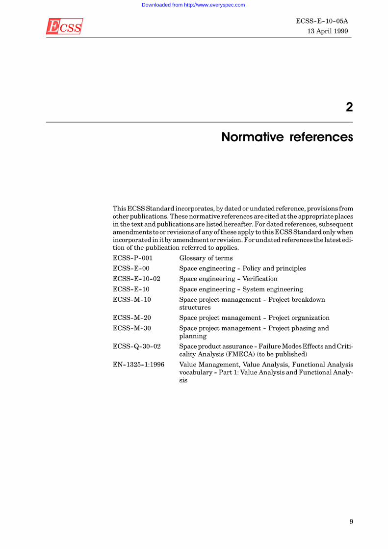
ThisECSSStandard incorporates, by dated or undatedreference, provisions fromother publications. These normative references are cited at the appropriateplacesin the text and publicationsare listedhereafter. For dated references, subsequentamendments toor revisionsof anyof theseapply to thisECSSStandard onlywhenincorporated in itbyamendmentorrevision.Forundatedreferencesthe latestedi-tion of the publication referred to applies.
ECSS--P--001 Glossary of terms
ECSS--E--00 Space engineering -- Policy and principles
ECSS--E--10--02 Space engineering -- Verification
ECSS--E--10 Space engineering -- System engineering
ECSS--M--10 Space project management -- Project breakdownstructures
ECSS--M--20 Space project management -- Project organization
ECSS--M--30 Space project management -- Project phasing andplanning
ECSS--Q--30--02 Space productassurance -- FailureModesEffects andCriti-cality Analysis (FMECA) (to be published)
EN--1325--1:1996 Value Management, Value Analysis, Functional Analysisvocabulary -- Part 1: Value Analysis and Functional Analy-sis
Downloaded from http://www.everyspec.com

ECSS13 April 1999ECSS--E--10--05A
10
(This page is intentionally left blank)
Downloaded from http://www.everyspec.com

ECSS 13 April 1999
ECSS--E--10--05A
11
3
Terms, definitions and abbreviated terms
3.1 Terms and definitionsThe following terms and definitions are specific to this standard in the sense thatthey are complementary or additional with respect to those contained inECSS--P--001.
3.1.1 ConstraintA characteristic, result or design feature which is made compulsory or has beenprohibited for any reason (EN 1325--1).
NOTE 1 Constraints are generally restrictions on the choice of solutionsin a system.
NOTE 2 Twokinds of constraints are considered, thosewhich concern sol-utions, and those which concern the use of the system.
NOTE 3 For example constraints can come fromenvironmental andoper-ational conditions, law, standards,market demand, investmentsand means availability, organization’s policy.
3.1.2 FunctionIntended effect of a system, subsystem, product or part (EN 1325--1).
NOTE Functionsshouldhaveasingledefinitepurpose.Functionnamesshould have a declarative structure (e.g. “Validate Telecom-mands”), and say “what” is to be done rather than “how”. Goodnamingallowsdesign componentswith strong cohesion tobeeas-ily derived.
3.1.3 Functional analysisThe technique of identifying anddescribing all functions of a system (EN1325--1).
3.1.4 Operational modeThemanner or way of operating. The mode is realized by a group of related func-tions or tasks required to accomplish a specific operation.
3.1.5 Operational scenarioA summary of sequences of events and the environment for a specific operation.
Downloaded from http://www.everyspec.com

ECSS13 April 1999ECSS--E--10--05A
12
3.2 Abbreviated termsThe following abbreviations are defined and used within this standard.
Abbreviation Meaning
FMECA Failure Modes Effects and Criticality Analysis
ROD Review of Design
RAMS Reliability Availability Maintainability and Safety
Downloaded from http://www.everyspec.com

ECSS 13 April 1999
ECSS--E--10--05A
13
4
Principles and methods of functional analysis
4.1 PrinciplesIn order to design, develop and prove any space engineering system, the missionand consequent functions, that the system shall perform, shall be clearly estab-lished. This functionality shall be distributed throughout the different design le-vels (e.g. systems, subsystems, units). This allocation of the system functions ina systematic way is an important step in establishing adesign whichmeets all thedesign objectives.
4.2 MethodsFunctionalanalysis is the techniqueof identifyinganddescribingall the functionsofasystem.Thepurposeof theanalysis is to identify andpartitionall the functionsof any system required to perform the intended mission.
The analysis shall be performed to establish the system functions and to controlthe distribution and maintenance of these functions in a systematic and usefulmanner. Three techniques, function tree, functional matrix and functional blockdiagram shall be described, although it is recognized that other representationscan also prove suitable.
At the top system level, the required functions shall be derived from the missionstatement andare the basis of the system functional specifications. All these func-tions may be considered ”external” functions.
The solution to meet these functions may require new lower level functions to beidentified which are a result of the chosen solution. These new functions mayeither be serviced at the system level where they were derived, in which case thefunction is satisfied, ormay be passed to a lower level. A function, which is passedto a lower level, is a higher level function for the recipient level.
As the detail of the design progresses, each tier of the design shall add additionalfunctions necessary to support the higher level functions. Both types of functionsmaybeeither solvedinternallywithinthesystemor refinedinto requirementsandfunctions to be met at some lower level engineering unit. Thus, some functionshave different levels of importance associated with them depending on how andwhere they originated. Some functions are readily achievable, while others arecomplex and expensive to meet. Often at the lower levels, solutions are availablewhich readily meet most of the functions or during development it shall be estab-lished that aparticular function is onlymetunder specific conditions. To establish
Downloaded from http://www.everyspec.com

ECSS13 April 1999ECSS--E--10--05A
14
the consequences and impact of not meeting a requirement or to allow a functionto be renegotiated, it shall be possible to establish the origins of any function.
Changes to requirements can arise at top system level, in which case the ”sub”--derived functions,whichare affectedat the lower tier level, shallbe readily identi-fiable. A realistic example of top system level changes occurs when the launch ve-hicle is changed and as a consequence, the vibration spectrum or human factorscan alter.
Functional analysis shall include different activities. The complexity of theanaly-ses shall develop considering the designmaturity, the evolution of the design andthe complexity of the mission. Of course the ultimate aim shall be to achieve thesimplest final design whichmeets all the system requirements and offers the bestvalue. This requires that all the functions are met and also partitioned in a logicmanner.
Functional analysis shall be approached in a systematic manner. Functionsshould not be passed from one system to another system of the same level, butshould be received from a higher level system and either serviced or further dis-tributed (and divided if necessary) to lower level systems.
Functional analysis shall exclude the assessment of the criticality of the functionsin terms of reliability and safety, but shall serve as the basis of the functional fail-ure analysis. FMECA requirements are described in ECSS Q--30--02.
Functional analysis shall also excludes any consideration of the engineering sol-ution required to service an identified function, until ”internal” functions areidentified as part of the required solution. By considering a system in terms offunctions (being the problem to solve) and not in terms of technology (a possiblesolution), alternative technologies shall not be excluded, duplication can beavoided and components standardization can be improved.
4.3 ObjectivesThe objectives of functional analysis shall be to:
a. identify or update the functional requirements;
b. ensure the functions are partitioned in an appropriate manner;
c. allow the traceability of the functions;
d. identify the interfaces between functions.
This allows a complex engineering system to be understood and realized.
4.4 Logic and implementation overview
4.4.1 PerformanceFunctional analysis shall be performed as part of the overall design developmentprocess.
4.4.2 ImplementationThe following functional analysis steps shall be implemented:
a. define the system and boundaries of the system under analysis by using therelevant requirements documents;
b. define the level of detail (depth of analysis);
c. identify the system functions/operational modes/operational scenarios;
d. represent the system by preparing the function tree(s), or functional ma-trix(ces), or functional block diagram(s).
The sequence of steps outlined above shall be valid for alluses, but the stepswhichare applied shall be determined on a case by case basis. The most common repre-
Downloaded from http://www.everyspec.com

ECSS 13 April 1999
ECSS--E--10--05A
15
sentation of the system is the function tree. The whole process is illustrated inFigure 1.
Functional requirementsPerformance requirementsSupport requirementsExternal interfacerequirements
Operational constraintsEnvironmental constraintsSafety and reliabilityconstraints
Define the systemUnderstand the capabilitiesand constraints of thesystem for all activitiesrequired to be performedand the external interfaces.
Definition of the systemand its external interfaces.
INPUT ACTIVITY OUTPUT
Contractual requirementsDesign maturity
Define the level ofdetail
Define the level of detail towhich the functionalrepresentation can usefullybe defined given the projectdefinition, complexity andresources available.
Externalsystem 3
Externalsystem 2
Externalsystem 1
System
Specification of level ofdetail of the functionalmodel.
Identify the functionsIdentify and decompose thefunctions of the system.
Definition of:D missionD mission phasesD operational sequences
Prepare tree modelArrange functions in anhierarchical tree structure.Define top level functionsfirst and decompose tolower level functions.
Prepare functionalmatrix
Arrange functions in matrixform to show functionalinterrelationships.
Functional requirementupdates and tree model
Functional matrix
Prepare functionalblock diagram
Arrange functions to showinput/output flow betweenfunctional entities.
Functional block diagram
Figure 1: Functional analysis implementation overview
Downloaded from http://www.everyspec.com

ECSS13 April 1999ECSS--E--10--05A
16
4.4.3 Functional statusFunctional analysis shall reflect the functional status of the system design. Eachiterationof functionalanalysisshallprovidemoredetailat lower levelsof thefunc-tional system hierarchy.
4.5 Process
4.5.1 System definitionA system shall be designed to meet a given objective, i.e. satisfy the requirementof theusersbyperformingaspecifiedsetof functions. It canbeaffectedby theenvi-ronment, actedupon by external systems or act itself upon the environment or ex-ternal system. The users and the environment are outside the system.
a. The boundaries of a system or a product shall be defined by its relationshipwith the different external elements.
External elements shall be users, the environment and the external systems.The system engineering process shall begin with the identification of therequirement, which is linked to a given user in a given situation and isconditioned by place, time and environment (e.g. humidity, ice). The givensituation, the place, the environment and interfaces with external systemsgenerate constraints.
b. Therequirementsandtheconstraintsshallbedescribed intermsof functions,not in terms of solutions.
During its life cycleasystemor aproductmaybe placed in differentsituationsand environments, which in turn generate constraints. Situations andenvironmentsmay be characterized as nominal, worst case or contingency asrelevant.
c. The different constraints generated by the different encountered conditionsof a system shall be taken into account.
d. The functionsand theconstraints shallbe completedby performancecriteria.
4.5.2 Definition of the level of detailThe level of detail in performing functional analysisshall bedeterminedbydesignmaturity and it normally increases during the project life cycle.
Therefore, to avoid a non-productive level of detail, the analyst shall have a clearunderstandingof theanalysisobjectivesapplicable to the specific project phase forwhich the design is considered current.
a. The level of detail of functional analysis shall be described and documented.
b. The level of detail shall be in accordance with the contractual requirementsand with the design maturity.
4.5.3 Identification of functionsA functionmay be decomposed into lower level functions.This divisionof the func-tionsofasystem,which shall start fromthe functional specification, isanessentialpart of functional analysis, and results in a hierarchical structure of functions.
Functional analysis shall:
a. provide the identification of the functions of the system;
b. identify the functions required to be performed in the different operationalscenarios of the analysed mission;
c. identify the functions required by the different operational modes of the sys-tem.
Operational modes shall include contingency modes induced by failures,faults or operator errors);
Downloaded from http://www.everyspec.com
ECSS 13 April 1999
ECSS--E--10--05A
17
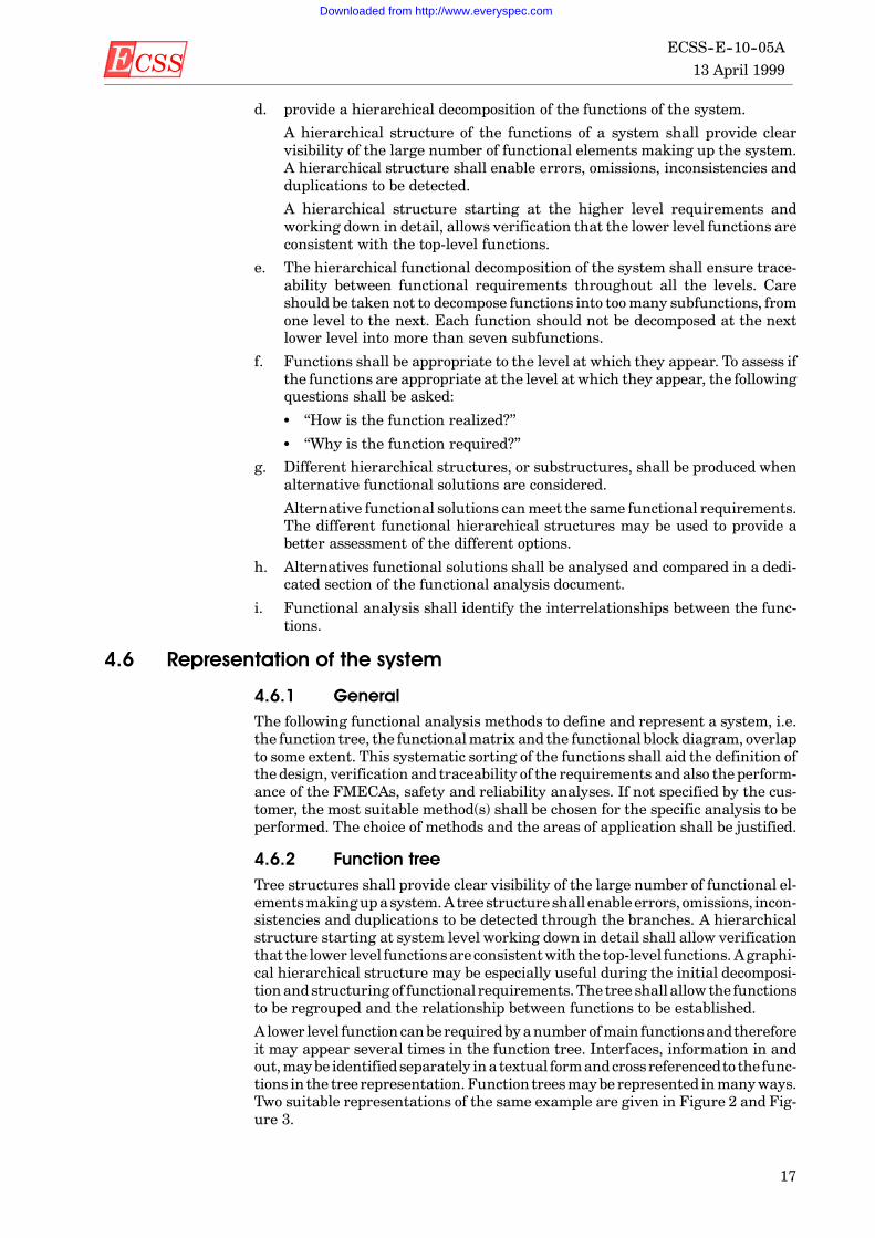
d. provide a hierarchical decomposition of the functions of the system.
A hierarchical structure of the functions of a system shall provide clearvisibility of the large number of functional elements making up the system.A hierarchical structure shall enable errors, omissions, inconsistencies andduplications to be detected.
A hierarchical structure starting at the higher level requirements andworking down in detail, allows verification that the lower level functions areconsistent with the top-level functions.
e. The hierarchical functional decomposition of the system shall ensure trace-ability between functional requirements throughout all the levels. Careshould be taken not to decompose functions into toomany subfunctions, fromone level to the next. Each function should not be decomposed at the nextlower level into more than seven subfunctions.
f. Functions shall be appropriate to the level at which they appear. To assess ifthe functions are appropriate at the level at which they appear, the followingquestions shall be asked:
S “How is the function realized?”
S “Why is the function required?”
g. Different hierarchical structures, or substructures, shall be produced whenalternative functional solutions are considered.
Alternative functional solutions canmeet the same functional requirements.The different functional hierarchical structures may be used to provide abetter assessment of the different options.
h. Alternatives functional solutions shall be analysed and compared in a dedi-cated section of the functional analysis document.
i. Functional analysis shall identify the interrelationships between the func-tions.
4.6 Representation of the system
4.6.1 GeneralThe following functional analysis methods to define and represent a system, i.e.the function tree, the functionalmatrix and the functional block diagram, overlapto some extent. This systematic sorting of the functions shall aid the definition ofthe design, verification and traceability of the requirements andalso the perform-ance of the FMECAs, safety and reliability analyses. If not specified by the cus-tomer, the most suitable method(s) shall be chosen for the specific analysis to beperformed. The choice of methods and the areas of application shall be justified.
4.6.2 Function treeTree structures shall provide clear visibility of the large number of functional el-ementsmakingupasystem.Atreestructureshall enableerrors, omissions, incon-sistencies and duplications to be detected through the branches. A hierarchicalstructure starting at system level working down in detail shall allow verificationthat the lower level functionsare consistentwith the top-level functions. Agraphi-cal hierarchical structure may be especially useful during the initial decomposi-tionandstructuring of functional requirements.The tree shallallow the functionsto be regrouped and the relationship between functions to be established.
A lower level function canberequiredbyanumber ofmain functionsandthereforeit may appear several times in the function tree. Interfaces, information in andout,maybe identifiedseparately inatextual formandcrossreferencedto thefunc-tions in the tree representation. Function treesmaybe represented inmanyways.Two suitable representations of the same example are given in Figure 2 and Fig-ure 3.
Downloaded from http://www.everyspec.com

ECSS13 April 1999ECSS--E--10--05A
18
a. Afunction tree shallbebasedon thesystemrequirements, functionalrequire-ments, and already defined functions.
b. A function tree shall specify the level in the functional hierarchy used for itspreparation.
c. Each functional requirement in the reference set of requirements shall be ar-ranged in a hierarchical manner.
d. Functions shall be decomposed into lower level functions. At the top level, thetree shall beagraphical representation of the systemrequirements, withpar-allelhierarchies for eachofthedifferentmajor functions.Each levelof thetreeshall represent the system functions at that specific level of abstraction. Itshall provide similar levels of detail for each of the functions represented atthat level. Functions at level “n” shall be decomposed into functions of level“n+1”.
e. Functions different from those traceable to the reference set of requirementsshall not be introduced.
f. All functions shall be numbered in a manner allowing the higher level func-tions to be readily identified.
g. All functionsshall benumbered inamannerallowing anyexisting lower levelfunctions to be readily identified.
h. Functional levels shall not be omitted.
i. No functions shall be inserted between levels of the function tree.
j. Alternative functional solutions to insure the required functions shall be in-vestigated and represented by different function trees.
k. Allapparentinconsistencies inthenomenclature, functionality andstructureof the function tree shall be identified and documented. Identified inconsis-tencies should be removed or rational for retention should be provided.
l. Functionsrequired to satisfy acustomer’s requirementshall bedistinguishedfrom those required to satisfy a requirement generated by the selected func-tional solutions.
Function 1
Function 1.1 Function 1.2 Function 1.3
Function1.1.1
Function1.2.1
Function1.2.2
Function 2.1 Function 2.2
Function2.1.2
Function2.2.1
Function2.2.2
Function1.1.2
Function2.1.1
System functions
Function 2
more level 1 functions
more level 2 functionsmore level 2 functions
lower level functions lower level functions
Figure 2: Function tree
Downloaded from http://www.everyspec.com

ECSS 13 April 1999
ECSS--E--10--05A
19
System functions
more level 1 functions
Function 1
Function 1.1
Function 1.2
Function 1.3
Function1.1.1
Function1.2.1
Function1.1.2
more level 2 functions
Function1.2.2
Function 2
Function 2.1
Function 2.2
Function 2.3
Function2.1.1
Function2.2.1
Function2.1.2
more level 2 functions
Function2.2.2
Figure 3: Function tree
Downloaded from http://www.everyspec.com

ECSS13 April 1999ECSS--E--10--05A
20
4.6.3 Functional matrixFunctionalmatrices should be used to complement the function tree, to representthe relationship between lower and higher functions, and between functions andoperationalmodes/operational scenarios. They may cover the complete system orsome specific areas. A number of matrices at different levels may be used.
a. A functional matrix shall be based on system requirements, functional re-quirements, already defined functions and system functional hierarchy.
b. A functionalmatrix shall specify the level in the functionalhierarchy used forits preparation.
c. Different functional matrices shall be prepared to investigate and representselected alternative functional (design) solutions.
d. The scope of each functional matrix, i.e. the set of functions to be consideredand the type of relationship to be represented, shall be determined.
e. Each function of the functional matrix shall be identified by consistent andlogical function number.
Functionalmatrices,maybeusedtorepresentrelationshipsbetween, forexample:
D functions at different levelsD functions and operational modesD functions and operational scenariosD functions generated from the user requirementsD functionsgeneratedfromtheselectedfunctional solutions/technologicalprin-
ciplesAn example of a functional matrix is shown in Figure 4.
Downloaded from http://www.everyspec.com

ECSS 13 April 1999
ECSS--E--10--05A
21
Functional Matrix level 1 to level 2
Level 1Level 2 functions
Level 1functions Function
1.1Function
1.2Function
1.3... Function
2.1Function
2.2...
Function 1 × × ×
Function 2 × ×
...
Functional Matrix level 2 to level 3
Level 2Level 3 functions
Level 2functions Function
1.1.1Function1.1.2
Function1.2.1
Function1.2.2
Function2.1.1
Function2.1.2
Function2.2.1
Function2.2.2
...
Function1.1 × ×
Function1.2 × ×
Function1.3
...
Function2.1 × × ×
Function2.2 ×
...
Figure 4: Functional matrix
Downloaded from http://www.everyspec.com

ECSS13 April 1999ECSS--E--10--05A
22
4.6.4 Functional block diagramA functional blockdiagramshallbe asystemrepresentationwhich emphasizes in-terfaces and interrelationships between functional entities (input/output flows).
The diagram shall make use of a limited set of symbols (boxes, lines, arrows andtextual information) which analysts and designers use to represent a system ofany required size. Each block forms a part of thewhole and represents a function.Blocks shall be connected togetherby linesandarrowswhich giveorder anddirec-tion to the diagram. The lines shall not represent physical connections associatedto the blocks but their functional dependencies. (See Figure 5: Functional blockdiagram).
A functional blockdiagramrepresentationmay alsobe organized in aseries ofdia-grams, each with concise supporting text. In this case a high level overview dia-gram shall be used to represent thewhole subject. Each lower level diagram shallbe used to show a limited amount of detail about a well defined topic.
a. A functionalblockdiagramshallbebased onsystemrequirements, functionalrequirements, already defined functions and system functional hierarchy.
b. A functional block diagram shall specify the level in the functional hierarchyused for its preparation.
c. If a hierarchy of diagrams is used, each diagram shall be consistent with thediagrams prepared for adjacent levels.
d. Different functional block diagramsshall be prepared for the variousmissionphases and operational modes to display possible different impacts on theoverall mission.
e. Different functional block diagrams shall be prepared to investigate andrepresent selected alternative functional (design) solutions.
f. The functionalblockdiagramshallbeprepared forsingle levelsof thefunctiontree.
g. The functional block diagram shall describe the redundancy configuration.
h. Each block shall be identified by the consistent and logical function numbers.The function number shall be consistentwith any other functional represen-tation.
Downloaded from http://www.everyspec.com

ECSS 13 April 1999
ECSS--E--10--05A
23
Function 1.1
Function 1.2
Function 1.3
Function1.1.1
Function1.2.1
Function1.1.2
Function 2.1
Function 2.2
Function2.1.2
Function2.2.2
Level 2
Level 3
Function1.3.1
Function1.3.2
Function1.1.1
Function1.1.2
Function1.2.2
Figure 5: Functional block diagram
Downloaded from http://www.everyspec.com

ECSS13 April 1999ECSS--E--10--05A
24
4.7 Functional analysis and engineering disciplinesThe scope of this subclause describes the relationshipbetween functionalanalysistechniques and main aspects performed by engineering disciplines. It is an in-formative subclause but few requirements may be proposed when they are re-quired.
4.7.1 Functional analysis and requirementsA comprehensible and unambiguous functional specification shall be the basis toproperly manage a project, because:
D the cost of the future product or system depends on its functions andconstraints;
D the functional specification is the reference in terms of quality of the futureproduct;
D the responsibilities between customer and supplier shall be clearly defined.
For these reasons, the requirements of the functional specification shall be ex-pressed in termsof functionswith their performance criteria and level of perform-ance criteria and constraints, whatever method is used for identifying them.
To attain this objective, functional analysis may be used to identify the functionsthat the future product should perform and its constraints.
The most frequently used methods to capture the requirements are:
D the natural or intuitive search (more easily appliedwhen there is an existingproduct);
D the method of interaction with the external environment.Functional analysis shall then be used to represent the identified systemrequire-ments in a structured way to help establish the system functional specification.
4.7.2 Functional specificationThe preliminary functional system specification shall be one of the major outputsof the phase 0/phase A mission analysis activity by which user requirements areturned into preliminary functional requirements. The functional analysis ap-proach should be used to identify requirements in terms of functions and con-straints.Requirements for lower levelcontractorsshallbe formally imposedbythespecifications. Functional analysis shall then be used to support the requirementallocation process.
4.7.3 Off-the-shelf item assessmentAn “off-the-shelf” itemshall be introducedassoon aspossible in the designprocesssince itmay significantlymodify the function tree, functionalmatrix or block dia-gram. It may represent an alternative functional solution to the system.
If recurrent items from previous space projects are used, the functional analysisshall take into account the use of “off-the-shelf items” in the following way:
a. The functions, that the item “off-the-shelf” can perform, shall be clearlyidentified by the functional analysis of the item, or through its technical de-scription.
b. These functions shall be compared to the required functions that the itemhasto fulfil in the new system in order to ensure that all required functions areperformed by the item.
c. If the item performs additional functions compared to the required ones, thefunctional analysis shall determine if those functions are not contradictorywith the overall functions of the system.
Downloaded from http://www.everyspec.com

ECSS 13 April 1999
ECSS--E--10--05A
25
4.7.4 SoftwareSoftware design and development shall be part of the “system engineering” func-tion to define the overall requirements to be built. These derived functions shallbe expressed in a system technical specification. From this document, a decom-position of the system into subsystemsandapartitioningof thesystem/subsysteminto hardware and software shall be performed.
Thusthesystemrequirementsshallbeestablishedandthesoftwarerequirementsmay be separated from the hardware requirements. The optimum partition shallbe performed using a series of trade-off studies. Part of this comparative trade-offshall be a functional analysiswhich allows the complexity of the system to be con-sidered. Any of the conventional analysismethods describedmay beused to parti-tion the hardware and software.
a. The functional analysis shall be updated after the hardware and softwarepartitioning performed during the physical “architecture” design.
b. The functional analysis shall be used to identify the control and data flow be-tween functions.
As the software is detailed, the functional model shall be transformed into the“architectural” design by allocating the identified functions to software compo-nents and defining the control and data flow between them. This process shall beaided by the use of functional analysis trees.
However, where a function tree defines the data flow and control, care shall betaken to keep the software conventions of good programming which relate to therelative levels of the requirements being specified, the allowed“fan out”of the treeand the data flow. Where the arrows between functional boxes are being used todesign the data flow and control datahandling and the functional boxes representsubroutines, the function tree shall be adapted for software design ensuring thatthe variables enter and leave the subroutine via a common interface. Thus the ar-rows represent the pathway of the data both into and out of a subroutine. Return-ing to a main program directly via another subroutine shall not be permitted.
4.7.5 OperationsFunctionalanalysisshall consider theoperational constraintsandmaydetermineoperational requirements at spacecraft and ground segment level.
a. Functionalanalysisof operationsshall beperformedbefore the systemdesignis frozen and shall take place early in the design process because it couldmod-ify the function tree of the system by establishing new constraints.
Functional analysis shall influence the operational considerations in two direc-tions :
b. Functional analysis shall consider as performance criteria the impact of thedesign on the future operations of the system.
c. The operations shall be subject to a detailed functional analysis.
4.7.6 TraceabilityThe traceability of functions shall be an essential feature of a design. It shall allowthe design to be verified as complete and enables the significance of design non-compliances to be identified.
a. All functions shall be traceable.
b. All functions shall be backwards traceable. Backwards traceability shallallow the source of each requirement to be traced back to the function fromwhich it was derived and shall allow subfunctions to be traced back to theirhigher level “mother” functions.
c. All functions shall be forward traceable. Forward traceability shall establishthat each high level function has been implemented at the appropriate phase
Downloaded from http://www.everyspec.com

ECSS13 April 1999ECSS--E--10--05A
26
of thedesignandthatall functionshave been implemented (thedesign iscom-plete).
NOTE If the traceability requirements have been implemented in a rig-orous and proper manner, any backward untraceable functionsare unnecessary. Any functions which are not forward traceablehave been either omitted by the design or are implemented attheir current level.
4.7.7 VerificationVerification is the confirmationbyexaminationandprovisionof objectiveevidencethat thespecifiedrequirementshavebeen fulfilled (ISO8402:1994, adopted by theECSS--P--001).
It shallbe theactof reviewing, inspecting, testing, checking,auditing orotherwiseestablishingwhether items, processes, servicesordocumentsconformto thespeci-fied functions.
Verification may be separated into two classes of product, new designs and recur-rent builds.
D New designs shall be qualified demonstrating appropriate margins to provethe design is robust and meets all the design functions.
D Recurrent builds may require a lower level of acceptance verification todetermine the build and workmanship is as intended and the unit functionscorrectly.
a. All functions identified by the functional analysis shall be verified. There arefour practices by which the functions may be verified:
1. Testing
2. Analysis
3. Review of Design (ROD)
4. Similarity.
The applicable practice shall depend on the level of the review. Verification bytesting should be the preferred option but is not always possible.
b. All functions shall be identified in the design and verification plan andverifi-cation matrix.
c. A verification method for each function shall be identified.
d. Completeness of functional analysis shall be verified by analysis and ROD(The verification requirements are detailed in ECSS--10--02).
4.8 Functional analysis and other disciplines
4.8.1 Dependability and Safetya. Dependability and safety engineering should be an essential contribution to
functional analysis development to:
1. provide support in trade-off assessment between possible functional de-sign solutions;
2. provide inputs about the failure tolerance implementation approach atfunctional level;
3. identify thoseadditional functions required to respondto failuredetectionisolation and recovery requirements.
b. Functionalanalysis results shouldenable dependability and safety engineersto:
1. acquire the knowledge of the systembaseline and options in termsof oper-ational modes and functional design configuration ;
Downloaded from http://www.everyspec.com

ECSS 13 April 1999
ECSS--E--10--05A
27
2. support the RAMS requirements allocation at lower contractual levels;
3. support the criticality assessmentof functions in termsof response to faulttolerance and other RAMS requirements;
4. support the FMECA and safety analysis development at different levels;
5. build-up the reliability/availability modelling for a probability asses-sment.
4.8.2 Functional analysis and managementFunctional analysis should be a supporting tool (method/technique) for someacti-vities of themanagement process in order to contribute to the success of a project.
Management activities supported by functional analysis should be:
D identification of requirements;D definition of mission scenario;D definition of the baseline functional requirements for the system specifica-
tion;D definition of system functional architecture (system functions translated into
functionalarchitecture), elaborationof function tree (basis for constructionofproduct tree necessary for the creation of the project breakdown structures);
D comparison between alternative solutions;D handling of potential critical functions/conditions for the mission;D make or buy decision process.
Downloaded from http://www.everyspec.com

ECSS13 April 1999ECSS--E--10--05A
28
(This page is intentionally left blank)
Downloaded from http://www.everyspec.com

ECSS 13 April 1999
ECSS--E--10--05A
29
5
Functional analysis and project phases
5.1 ObjectivesFunctional analysis objectives shall differ with respect to the project phase. Thedepth and detail of the analysis shall be determined in view of the actual designmaturity reached.
Functional analysis shall mainly be conducted at top system level during phases0 and A, while it may be carried-out to different levels during B and C.
To be in linewith the objectives established byECSS--M--30 for each design phase,functional analysis requirements are addressed by the following subclauses.
5.2 Project phases
5.2.1 Phase 0During this phase functional analysis shall support the identification of require-ments and the definition of the overallmission scenario. Therefore the effort shallbe spent to provide:
a. representationof the identifiedpotential user requirements andexpectationsin terms of functions. It shall also include those functions identified by otherpossible product applications within the market or due to commonality withsimilar projects;
b. definition of the reference mission scenario, acceptable degraded modes andidentification of potential operational options to be further investigated;
c. assessment of all external constraints, in particular those imposed by the en-countered combination of operational environments;
d. assessment of the constraints related to each specific requirement or imposedby the interfaces with other products to be used in conjunction with.
5.2.2 Phase Aa. During the feasibilityphase functionalanalysisshallbeperformedtoprovide:
1. support to the feasibility assessment on the basis of the requirements ex-pressed or identified in the previous phase;
2. definition of a systemoperational concept able tomeet the perceivedprod-uct application and user expectations;
Downloaded from http://www.everyspec.com

ECSS13 April 1999ECSS--E--10--05A
30
3. assessmentof thevariouspossible functional conceptsby comparing theseconcepts against the requirements.
b. The outputs of this phase of functional analysis shall support negotiation anddefinition of the baseline functional requirements to be included in aprelimi-nary system specification. Therefore all system functions shall be specified,including interfacesandconstraints, foreachoperationalmodeof theproduct.
5.2.3 Phase Ba. Functional analysis carried out in this phase shall support the system func-
tional architecture definition. It shall mainly be carried out at system level,but the lower level contractors shallalso contribute to reflectall necessaryde-tails.
b. All primary system functions shall be translated into a functional architec-ture, but detail design shall not be finalized.
c. A detailed function tree shall be established to define hierarchical depen-dencies between functions at different levels, and to allow traceability frombeginning to end conditions.
d. Trade studies shall also be conducted within this phase to allocate require-ments to lower level functions, and to identify and resolve conflicts amongfunctional requirements.
e. The system functional architectural model shall be evaluated:
1. to verify links between functions, lower level functions and operationalmodes of the mission scenario during each mission phase;
2. to allow selection of an optimized solution between alternative functionalarchitectures;
3. to support the identification of potential critical functions as part ofFMECA (see ECSS--Q--30--02)
f. At the end of this phase functional analysis shall be able:
1. to establish and validate a definitive system architecture and freeze thefunctional system specification;
2. to establish a set of lower level functional requirements to support lowerlevel specifications definition;
3. to provide support for make-or-buy decisions.
5.2.4 Phase Ca. Functional analysis carried out in this phase shall support definition of the
system detailed design.
b. In this phase functional analysis shall be carried out by:
1. lower level contractors, to implement the applicable functional require-ments in their design;
2. primecontractor, toassessconformanceof lower leveldetaileddesignwiththe overall system functional architecture.
c. Functional analysis shall continue to support definition of new design items.The allocation of subfunctions betweenhardware, software and human oper-ations shall be supported by this analysis.
d. At the end of this phase functional analysis shall support:
1. finalization of the procurement specifications for all lower level compo-nents;
2. finalization of the interface control documents;
3. validation of the overall functional architecture;
Downloaded from http://www.everyspec.com

ECSS 13 April 1999
ECSS--E--10--05A
31
4. definition of the user manual, operational handbook and associated pro-cedures (e.g. in-orbit operations, ground operations, telemetry and tele-command lists, human tasks’ definition).
Downloaded from http://www.everyspec.com

ECSS13 April 1999ECSS--E--10--05A
32
(This page is intentionally left blank)
Downloaded from http://www.everyspec.com

ECSS 13 April 1999
ECSS--E--10--05A
33
Bibliography
CD--NA--16--096--EN--C:1995 II Value Management HandbookEuropean Commission publication
Downloaded from http://www.everyspec.com

ECSS13 April 1999ECSS--E--10--05A
34
(This page is intentionally left blank)
Downloaded from http://www.everyspec.com

ECSS 13 April 1999
ECSS--E--10--05A
35
ECSS Document Improvement Proposal1. Document I.D.ECSS--E--10--05A
2. Document Date13 April 1999
3. Document TitleFunctional analysis
4. Recommended Improvement (identify clauses, subclauses and include modified textand/or graphic, attach pages as necessary)
5. Reason for Recommendation
6. Originator of recommendation
Name: Organization:
Address: Phone:Fax:E--Mail:
7. Date of Submission:
8. Send to ECSS Secretariat
Name:W. KriedteESA--TOS/QR
Address:ESTEC, Postbus 2992200 AG NoordwijkThe Netherlands
Phone: +31--71--565--3952Fax: +31--71--565--6839E--Mail: [email protected]
Note: The originator of the submission should complete items 4, 5, 6 and 7.This form is available as a Word and Wordperfect--Template on internet under
http://www.estec.esa.nl/ecss/improve/
Downloaded from http://www.everyspec.com

ECSS13 April 1999ECSS--E--10--05A
36
(This page is intentionally left blank)
Downloaded from http://www.everyspec.com