ecss--e--20a - space.aau.dk · for space standardization european cooperation ecss space...
TRANSCRIPT
FOR SPACE STANDARDIZATION
EUROPEAN COOPERATION
ECSS
Space engineering
Electrical and electronic
ECSS SecretariatESA--ESTEC
Requirements & Standards DivisionNoordwijk, The Netherlands
ECSS--E--20A
4 October 1999

ECSS4 October 1999ECSS--E--20A
2
Published by: ESA Publications DivisionESTEC, P.O. Box 299,2200 AG Noordwijk,The Netherlands
ISSN: 1028-396X
Price: EUR 20
Printed in The Netherlands
Copyright 1999 E by the European Space Agency for the members of ECSS

ECSS 4 October 1999
ECSS--E--20A
3
Foreword
This Standard is one of the series of ECSS Standards intended to be applied to-gether for the management, engineering and product assurance in space projectsand applications. ECSS is a cooperative effort of the European Space Agency,National Space Agencies and European industry associations for the purpose ofdeveloping and maintaining common standards.
Requirements in this Standard are defined in terms of what shall be accom-plished, rather than in terms of how to organize and perform the necessary work.This allows existing organizational structures and methods to be applied wherethey are effective, and for the structures andmethods to evolve as necessary with-out rewriting the standards.
The formulation of this Standard takes into account the existing ISO 9000 familyof documents.
This Standard has been prepared by the ECSS Electrical and electronic Stan-dards Working Group, reviewed by the ECSS Technical Panel and approved bythe ECSS Steering Board.

ECSS4 October 1999ECSS--E--20A
4
(This page is intentionally left blank)

ECSS 4 October 1999
ECSS--E--20A
5
Contents list
Foreword 3. . . . . . . . . . . . . . . . . . . . . . . . . . . . . . . . . . . . . . . . . . . . . . . . . . . . . . . . .
1 Scope 9. . . . . . . . . . . . . . . . . . . . . . . . . . . . . . . . . . . . . . . . . . . . . . . . . . . . . . . .
2 Normative references 11. . . . . . . . . . . . . . . . . . . . . . . . . . . . . . . . . . . . . . . . .
3 Terms, definitions and abbreviated terms 13. . . . . . . . . . . . . . . . . . . . . . .
3.1 Terms and definitions 13. . . . . . . . . . . . . . . . . . . . . . . . . . . . . . . . . . . . . . . . . . . . . . .
3.2 Abbreviated terms 14. . . . . . . . . . . . . . . . . . . . . . . . . . . . . . . . . . . . . . . . . . . . . . . . .
4 General requirements 15. . . . . . . . . . . . . . . . . . . . . . . . . . . . . . . . . . . . . . . . .
4.1 Interface requirements 15. . . . . . . . . . . . . . . . . . . . . . . . . . . . . . . . . . . . . . . . . . . . .
4.2 Design requirements 16. . . . . . . . . . . . . . . . . . . . . . . . . . . . . . . . . . . . . . . . . . . . . . .
4.3 Safety 19. . . . . . . . . . . . . . . . . . . . . . . . . . . . . . . . . . . . . . . . . . . . . . . . . . . . . . . . . . . .
4.4 Preparation for delivery 19. . . . . . . . . . . . . . . . . . . . . . . . . . . . . . . . . . . . . . . . . . . . .
4.5 Parts, materials and processes 19. . . . . . . . . . . . . . . . . . . . . . . . . . . . . . . . . . . . . . .
4.6 Specific requirements on pyrotechnics 19. . . . . . . . . . . . . . . . . . . . . . . . . . . . . . .
4.7 Verification 19. . . . . . . . . . . . . . . . . . . . . . . . . . . . . . . . . . . . . . . . . . . . . . . . . . . . . . . .
5 Electrical power 21. . . . . . . . . . . . . . . . . . . . . . . . . . . . . . . . . . . . . . . . . . . . . . .
5.1 Functional description 21. . . . . . . . . . . . . . . . . . . . . . . . . . . . . . . . . . . . . . . . . . . . . .

ECSS4 October 1999ECSS--E--20A
6
5.2 Power requirements and budgets 21. . . . . . . . . . . . . . . . . . . . . . . . . . . . . . . . . . . .
5.3 Failure containment and redundancy 22. . . . . . . . . . . . . . . . . . . . . . . . . . . . . . . .
5.4 Energy generation 22. . . . . . . . . . . . . . . . . . . . . . . . . . . . . . . . . . . . . . . . . . . . . . . . .
5.5 Energy storage 23. . . . . . . . . . . . . . . . . . . . . . . . . . . . . . . . . . . . . . . . . . . . . . . . . . . .
5.6 Power conditioning and control 27. . . . . . . . . . . . . . . . . . . . . . . . . . . . . . . . . . . . . .
5.7 Power distribution and protection 29. . . . . . . . . . . . . . . . . . . . . . . . . . . . . . . . . . . .
5.8 Safety 30. . . . . . . . . . . . . . . . . . . . . . . . . . . . . . . . . . . . . . . . . . . . . . . . . . . . . . . . . . . .
5.9 High voltage engineering 30. . . . . . . . . . . . . . . . . . . . . . . . . . . . . . . . . . . . . . . . . . .
5.10 Verification 30. . . . . . . . . . . . . . . . . . . . . . . . . . . . . . . . . . . . . . . . . . . . . . . . . . . . . . . .
6 Electromagnetic Compatibility (EMC) 33. . . . . . . . . . . . . . . . . . . . . . . . . . .
6.1 Policy 33. . . . . . . . . . . . . . . . . . . . . . . . . . . . . . . . . . . . . . . . . . . . . . . . . . . . . . . . . . . .
6.2 General 34. . . . . . . . . . . . . . . . . . . . . . . . . . . . . . . . . . . . . . . . . . . . . . . . . . . . . . . . . .
6.3 Spacecraft charging protection programme 35. . . . . . . . . . . . . . . . . . . . . . . . . .
6.4 Verification 36. . . . . . . . . . . . . . . . . . . . . . . . . . . . . . . . . . . . . . . . . . . . . . . . . . . . . . . .
7 Radio frequency systems 39. . . . . . . . . . . . . . . . . . . . . . . . . . . . . . . . . . . . . .
7.1 Functional description 39. . . . . . . . . . . . . . . . . . . . . . . . . . . . . . . . . . . . . . . . . . . . . .
7.2 General 39. . . . . . . . . . . . . . . . . . . . . . . . . . . . . . . . . . . . . . . . . . . . . . . . . . . . . . . . . .
7.3 Antenna 40. . . . . . . . . . . . . . . . . . . . . . . . . . . . . . . . . . . . . . . . . . . . . . . . . . . . . . . . . .
7.4 Multipaction and gas discharge 40. . . . . . . . . . . . . . . . . . . . . . . . . . . . . . . . . . . . .
7.5 Passive intermodulation 40. . . . . . . . . . . . . . . . . . . . . . . . . . . . . . . . . . . . . . . . . . . . .
7.6 Safety 41. . . . . . . . . . . . . . . . . . . . . . . . . . . . . . . . . . . . . . . . . . . . . . . . . . . . . . . . . . . .
7.7 Verification 41. . . . . . . . . . . . . . . . . . . . . . . . . . . . . . . . . . . . . . . . . . . . . . . . . . . . . . . .
8 Optical systems 43. . . . . . . . . . . . . . . . . . . . . . . . . . . . . . . . . . . . . . . . . . . . . . .
8.1 Functional description 43. . . . . . . . . . . . . . . . . . . . . . . . . . . . . . . . . . . . . . . . . . . . . .
8.2 General requirements 43. . . . . . . . . . . . . . . . . . . . . . . . . . . . . . . . . . . . . . . . . . . . . .
8.3 Safety 46. . . . . . . . . . . . . . . . . . . . . . . . . . . . . . . . . . . . . . . . . . . . . . . . . . . . . . . . . . . .
8.4 Verification 46. . . . . . . . . . . . . . . . . . . . . . . . . . . . . . . . . . . . . . . . . . . . . . . . . . . . . . . .
Annex A (normative) EMC control plan - Document Requirements
Definition (DRD) 47. . . . . . . . . . . . . . . . . . . . . . . . . . . . . . .
A.1 Introduction 47. . . . . . . . . . . . . . . . . . . . . . . . . . . . . . . . . . . . . . . . . . . . . . . . . . . . . . .
A.2 Scope and applicability 47. . . . . . . . . . . . . . . . . . . . . . . . . . . . . . . . . . . . . . . . . . . .
A.3 References 47. . . . . . . . . . . . . . . . . . . . . . . . . . . . . . . . . . . . . . . . . . . . . . . . . . . . . . .
A.4 Terms, definitions and abbreviated terms 48. . . . . . . . . . . . . . . . . . . . . . . . . . . . .
A.5 Description and purpose 48. . . . . . . . . . . . . . . . . . . . . . . . . . . . . . . . . . . . . . . . . . .
ECSS 4 October 1999
ECSS--E--20A
7
A.6 Application and interrelationship 48. . . . . . . . . . . . . . . . . . . . . . . . . . . . . . . . . . . . .
A.7 EMC control plan preliminary elements 48. . . . . . . . . . . . . . . . . . . . . . . . . . . . . . .
A.8 Content 49. . . . . . . . . . . . . . . . . . . . . . . . . . . . . . . . . . . . . . . . . . . . . . . . . . . . . . . . . .
Annex B (normative) Electromagnetic effects verification plan -
Document Requirements Definition (DRD) 53. . . . . . . .
B.1 Introduction 53. . . . . . . . . . . . . . . . . . . . . . . . . . . . . . . . . . . . . . . . . . . . . . . . . . . . . . .
B.2 Scope and Applicability 53. . . . . . . . . . . . . . . . . . . . . . . . . . . . . . . . . . . . . . . . . . . .
B.3 References 53. . . . . . . . . . . . . . . . . . . . . . . . . . . . . . . . . . . . . . . . . . . . . . . . . . . . . . .
B.4 Terms, definitions and abbreviated terms 53. . . . . . . . . . . . . . . . . . . . . . . . . . . . .
B.5 Description and purpose 54. . . . . . . . . . . . . . . . . . . . . . . . . . . . . . . . . . . . . . . . . . .
B.6 Application and interrelationship 54. . . . . . . . . . . . . . . . . . . . . . . . . . . . . . . . . . . . .
B.7 EMEVP preliminary elements 54. . . . . . . . . . . . . . . . . . . . . . . . . . . . . . . . . . . . . . . .
B.8 Content 55. . . . . . . . . . . . . . . . . . . . . . . . . . . . . . . . . . . . . . . . . . . . . . . . . . . . . . . . . .
Annex C (normative) Electromagnetic effects verification report -
Document Requirements Definition (DRD) 57. . . . . . . .
C.1 Introduction 57. . . . . . . . . . . . . . . . . . . . . . . . . . . . . . . . . . . . . . . . . . . . . . . . . . . . . . .
C.2 Scope and Applicability 57. . . . . . . . . . . . . . . . . . . . . . . . . . . . . . . . . . . . . . . . . . . .
C.3 References 57. . . . . . . . . . . . . . . . . . . . . . . . . . . . . . . . . . . . . . . . . . . . . . . . . . . . . . .
C.4 Terms, definitions and abbreviated terms 57. . . . . . . . . . . . . . . . . . . . . . . . . . . . .
C.5 Description and purpose 58. . . . . . . . . . . . . . . . . . . . . . . . . . . . . . . . . . . . . . . . . . .
C.6 Application and interrelationship 58. . . . . . . . . . . . . . . . . . . . . . . . . . . . . . . . . . . . .
C.7 EMEVR preliminary elements 58. . . . . . . . . . . . . . . . . . . . . . . . . . . . . . . . . . . . . . . .
C.8 Content 59. . . . . . . . . . . . . . . . . . . . . . . . . . . . . . . . . . . . . . . . . . . . . . . . . . . . . . . . . .
Bibliography 61. . . . . . . . . . . . . . . . . . . . . . . . . . . . . . . . . . . . . . . . . . . . . . . . . . . . .
Figures
Figure 1: Output impedance mask (Ohm) 28. . . . . . . . . . . . . . . . . . . . . . . . . . . . . . . . . . . . . . . .
Tables
Table 1: Environmental factors in the design of optical instruments 45. . . . . . . . . . . . . . . . . . .

ECSS4 October 1999ECSS--E--20A
8
(This page is intentionally left blank)
ECSS 4 October 1999
ECSS--E--20A
9
1
Scope
This Standard establishes the basic rules and general principles applicable to theelectrical, electronic, electromagnetic, microwave and optical engineering pro-cesses. It specifies the tasks of these engineering processes and the basic perform-ance and design requirements in each discipline.
It defines the terminology for the activities within these areas.
It defines the specific requirements for electrical subsystems and payloads, deriv-ing from the system engineering requirements laid out in the Space System En-gineering Standard ECSS--E--10.

ECSS4 October 1999ECSS--E--20A
10
(This page is intentionally left blank)

ECSS 4 October 1999
ECSS--E--20A
11
2
Normative references
The following normative documents contain provisions which, through referencein this text, constitute provisions of this ECSS Standard. For dated references,subsequent amendments to, or revisions of, any of these publications do not apply.However, parties to agreements based on this ECSS Standard are encouraged toinvestigate the possibility of applying the most recent editions of the normativedocuments indicated below. For undated references, the latest edition of the nor-mative document referred to applies.
ECSS--P--001 Glossary of terms
ECSS--E--00 Space engineering -- Policy and principles
ECSS--E--10 Space engineering -- System engineering
ECSS--E--30 Space engineering -- Mechanical (to be published)
ECSS--E--50 Space engineering -- Communication (to be published)
ECSS--M--40 Space project management -- Configuration management
ECSS--Q--20 Space product assurance -- Quality assurance
ECSS--Q--30 Space product assurance -- Dependability
ECSS--Q--40 Space product assurance -- Safety
ECSS--Q--60 Space product assurance -- Electrical, electronic and elec-tromechanical (EEE) components
ECSS--Q--60--11 Space product assurance -- Derating and application rules(to be published)
ECSS--Q--70 Space product assurance -- Materials, mechanical partsand processes
ECSS--Q--70--28 Space product assurance -- The repair and modification ofprinted circuit board assemblies for space use (to be pub-lished)
IEC--60825 Safety of laser products
IEC--60479 Effects of current on human beings and livestock
IEEE 145--1993 Standard Definitions of Terms for Antennas
IEEE C95.1--1991 Safety Levels with Respect to Human Exposure to RadioFrequency Electromagnetic Fields, 3 kHz to 300 GHz
IEEE 149--1979 Test Procedures for Antennas(R 1990)

ECSS4 October 1999ECSS--E--20A
12
(This page is intentionally left blank)
ECSS 4 October 1999
ECSS--E--20A
13
3
Terms, definitions and abbreviated terms
3.1 Terms and definitionsThe following terms and definitions are specific to this Standard in the sense thatthey are complementary or additional with respect to those contained inECSS--P--001.
3.1.1 Centroid Error Function (CEF)Difference between the position of the barycentre of the point spread function(PSF), calculated by means of a suitable algorithm, and the theoretical positionof the PSF centre, given by the intersection of the corresponding chief ray withthe image plane. The centroid algorithm evaluates the position of the PSF energybarycentre and it is based on the energy measurement on a predeterminednumber of pixels in the image plane.
3.1.2 Encircled Energy Function (EEF)The fraction of the PSF energy which lies within a circle, evaluated as a functionof the circle radius.
3.1.3 Field Of View (FOV)Angular extent of the object space which can be detected by an optical system orinstrument. (The FOV may not be always symmetrical about the optical axis).
3.1.4 Instantaneous Field Of View (IFOV)Angular extent of the object space which can be detected by an optical system orinstrument, during a negligible time interval. (The IFOVmay not be always sym-metrical about the optical axis).
3.1.5 Line Spread Function (LSF)One-dimensional transverse energy distribution in the image of a narrow slit ob-ject.
3.1.6 Modulation Transfer Function (MTF)The modulation transfer function is the modulus of the optical transfer function.Considering a sine wave pattern object, the MTF is found to be the ratio of themodulation in the image to that in the object as a function of the spatial frequencyof the sine wave pattern.
ECSS4 October 1999ECSS--E--20A
14
3.1.7 Noise Equivalent Power (NEP)The Noise Equivalent Power is the value of the detector input power which pro-duces a detector output equal to the r.m.s. noise output within a stated bandwidthat a stated frequency.
3.1.8 Optical Transfer Function (OTF)It is the normalized Fourier transform of the point spread function
3.1.9 Point Spread Function (PSF)Two dimensional energy distribution in the image of an object point.
3.1.10 Wavefront error (WFE)Distribution of the distance between the wavefront exiting froman optical systemand a reference wavefront or surface, measured on the normal to the referencewavefront and expressed in wavelength units.
3.2 Abbreviated termsThe following abbreviated terms are defined and used within this Standard.
Abbreviation Meaning
AC Alternative Current
BOL Beginning-of-Life
CEF Centroid Error Function
CVCM Collected Volatile Condensable Material
DC Direct Current
DOD Depth of Discharge
DRD Document Requirements Definition
EED Electroexplosive Device
EEF Encircled Energy Function
EMEVP Electromagnetic Effects Verification Plan
EMEVR Electromagnetic Effects Verification Report
EMI Electromagnetic Interference
EOL End-of-Life
ESD Electrostatic Discharge
FOV Field of View
IFOV Instantaneous Field of View
I-V Current-Voltage
LSF Line Spread Function
MLI Multi-Layer Insulation
MTF Modulation Transfer Function
NEP Noise Equivalent Power
OTF Optical Transfer Function
PCB Printed Circuit Board
PSF Point Spread Function
RF Radio Frequency
r.m.s. root-mean-square
TML Total Mass Loss
WFE Wavefront error
VSWR Voltage Standing Wave Ratio
ECSS 4 October 1999
ECSS--E--20A
15
4
General requirements
4.1 Interface requirementsECSS--E--10A requires that interfaces external or internal to a system are ad-equately specified (4.2.5) and verified (4.6). The following requirements addressthis issue and shall be processed in phase B, C and D of a project as requested in5.5 of ECSS--E--10A.
4.1.1 Signals interfacesa. Interface engineering shall ensure that the characteristics on both sides of
each interface are compatible, including the effects of the interconnectingharness.
b. In order to minimize the number of interface types, standard interface cir-cuitry shall be defined to be applied throughout a project according to ECSS--E--50.
c. Circuits receiving high level telecommands for direct execution of amajor re-configuration function or other critical function shall include noise discri-mination filtering such that spurious commands of nominal peak-to-peakamplitude and of less than 10 %of the nominal command duration at arepeti-tion period of 20 % of the nominal command duration are ignored. This re-quirement does not apply to direct commands on relay coils.
d. The application of signals to an unpowered unit shall not cause damage tothat unit. An undefined status at the inputs of a powered unit shall not causedamage to this unit.
e. Signal interfaces shall withstand positive or negative voltages that are ac-cessible on the same connector. Signal interfaces shall withstand maximumpositive and negative fault voltages accessible on the same connector.
f. Provision shall be included to override any critical on-board autonomousfunction and to monitor its status, except where hazardous to the mission.
g. Any circuit intended to receive a signal shall include noise discriminationfiltering compatible with the information content of the signal received.
4.1.2 Commandsa. Every command that is required by the spacecraft shall be evaluated for criti-
cality. The criticality of a command is measured as its impact on the mission
ECSS4 October 1999ECSS--E--20A
16
in case of inadvertent function (erroneous transmission), incorrect function(aborted transmission) or loss of function.
S Category 1 criticality: Loss of mission.
S Category 2 criticality: Temporary interruption of spacecraft perform-ance, recoverable by ground command.
S Category 3 criticality: Causes no or minor degradation, recoverableby ground command.
The command criticality shall be assessed at equipment level and confirmedat subsystem/system level.
b. All executable commands shall be acknowledged by telemetry. The acknowl-edgment shall be explicit.
c. The function of an executable command shall not change throughout amission and shall not depend on the history of previous commands.
d. Commands for which the criticality is category 1 shall require at least twoseparate commands for execution: an arm/safe or enable/disable followed byan execute command.
e. It shall be possible to repeat all executable commands numerous times with-out degradation of the function, or causing a change of status.
f. On-board processor commands:
S Processor and simple logic circuits shall not be able to issue category 1critical commands without a ground commanded arm/safe or enable/disable command.
S Any on-board processing which issues commands to reconfiguresubsystems or payloads shall be overridable and potentially inhibited byground command.
S Configuration of a subsystem or equipment shall be possible from groundwithout intervention of the on-board processor.
4.1.3 Telemetrya. Telemetry data shall permit unambiguous monitoring, throughout the
mission of the spacecraft subsystems and payloads configuration up to all re-configurable elements.
b. The precision, range and time resolution of any telemetry channel shall beconsistent with requirements on tolerances on the parameter to be moni-tored.
c. All mainbus load currents shall be monitored by telemetry, to allow togetherwith the bus voltage telemetry a complete monitoring of a mainbus powerload.
4.2 Design requirements
4.2.1 Failure containment and redundancya. A single failure shall not propagate outside a single reconfigurable element.
b. Redundant functions shall be routed separately, preferably via redundantharness and physically separated connectors.
c. Redundant functions shall be physically separated and thermally decoupled,as a minimum, in a different package (e.g. PCB, Hybrid and Integrated Cir-cuit), to avoid failure propagation.
d. For multi cavity hybrids, redundant/protection functions shall be located ina different cavity.

ECSS 4 October 1999
ECSS--E--20A
17
e. Any equipment dissipating more than 20 W in nominal or failure conditionshall include a temperature monitoring capability.
f. In case of signal cross-strapping, no failure of either interface circuit shallpropagate to the other one.
g. Essential functions are those functions without which:
S the satellite operator cannot recover the spacecraft, following anyconceivable on-board or ground-based failure;
S the spacecraft cannot be commanded;
S the satellite permanently loses attitude and orbit control;
S the satellite consumables (e.g. fuel and energy) are depleted to such anextent that more than 10 % of the satellite’s lifetime is affected;
S the safety of crew is threatened.
Equipment providing essential functions shall not rely on other functions(e.g. synchronization and auxiliary supply) which are centrally generated:any such equipment shall be capable of operating independently of anyexternal synchronization and auxiliary power supply.
h. All units that need to be powered during launch shall be designed for criticalpressure and this shall be verified by test.
4.2.2 Data processingAll operational and scientific data require processing for acquisition, algorithmapplication, transmission and storage. Data processing includes the man ma-chine interface, if any.
The data processing system shall include all hardware and software elementsused for that purpose (e.g. microprocessor and its instruction set, interfacemeans, data busses and remote terminals).
a. The architectural design shall be chosen in accordance with the recommen-dations of ECSS--E--50.
b. All elements shall conform to proven standards as defined in ECSS--E--50.
c. All processors shall have a minimum 50 % margin in memory size and loadfactor at PDR (Preliminary Design Review), taking into account the pro-jected peak demand. This margin requirement does not apply to dedicatedstate machines where the bounds are precisely known.
The margin shall be periodically reviewed during project development.
d. System data busses and individual interfaces shall meet the peak demandswith a margin of 50 %. This peak demand and the margin shall be period-ically reviewed during the project development.
e. Reset or data corruption of functional chain at equipment level shall be keptto a rate of occurrence less or equal to 10--4 per day for worst case conditionsof environment.
4.2.3 Electrical connectorsa. All connectors carrying source power shall be female type.
b. All test connectors on a unit shall be female type.
c. The use of a connector saver for ground testing shall in no way alter the per-formance of the equipment.
d. Connectors or routing of harness shall be designed to avoid inadvertent con-nection of wrong equipment. This should be done by using keyed connectorsand adequate positioning of connectors. Where design considerations requireconnectors of similar configuration in close proximity, proper keying ormark-ing shall prevent erroneous mating.

ECSS4 October 1999ECSS--E--20A
18
e. If the equipment has several connectors, visibility and clearance around eachof them shall be such as to allow mating or demating without disturbingothers already in place or necessitate special custom-made tooling. Possibleinsertion of a breakout box for trouble shooting should be considered.
f. Single wire and connector, externally or internally to a unit shall not be usedto exchange mission-critical signals. Mission-critical assemblies shall usephysically separated connectors and boards.
g. For pyrotechnics supplies and signals, specific requirements as per sub-clause 4.6 of this standard shall be applied. Otherwise, as a rule, differentconnectors shall be used for power and signals. When this is not feasible, asa minimum, power, and signals and telemetry shall be separated in the con-nector by a set of unused pins in order to avoid failure propagation.
h. Spare contacts or sockets shall be available on each connector and should beeasily accessible.
i. At least one contact per connector shall be connected to the unit structure toconnect shields via conducting backshells of connectors.
j. Each signal and its corresponding return shall, wherever feasible, be locatedon adjacent contacts.
4.2.4 Testinga. Test/stimulus points shall be accessible without the need to modify the elec-
trical configuration of an item of equipment and shall be suitably protectedfor flight operation.
b. Dedicated test connectors shall be used.
c. It shall be possible to test the redundant function of a closed unit.
d. Test points on equipment shall be protected against damage up to the maxi-mum system voltage and unintentional connections of these points to groundshould not influence the nominal operation of the equipment.
e. Unused stimulus points on equipment and payload shall not provoke un-wanted operation.
f. Each protection circuit and each hot redundant function shall be testable onground at system level.
4.2.5 Mechanical requirementsThe mechanical design of electrical or optical equipment shall conform toECSS--E--30.
4.2.6 Thermal requirementsThe thermal design of electrical or optical equipment shall conform toECSS--E--30.
4.2.7 Dependability requirementsa. Dependability analyses shall be performed according to ECSS--Q--30.
b. Electrical parts shall be derated according to ECSS--Q--60--11.
c. Each item shall be directly interchangeable in form, fit, and function withother equipment of the same part number and of the same qualificationstatus. The performance characteristics and dimensions of the units shall besufficiently uniform to permit equipment interchange without unforeseenadjustments and recalibration.
d. When components operating in a single event (e.g. fuses) are used, 4 timesthe needed quantity for flight units shall be procured as one lot: 25 % for thelot acceptance test, 25 % for flight use, 25 % for spares and the remaining25 % for a confirmation test near to the launch date. For large quantities, the
ECSS 4 October 1999
ECSS--E--20A
19
number of extra necessary components implied by this requirement may bereduced.
4.3 SafetyEquipment shall be designed to eliminate potential hazards to the maximum ex-tent. Practical hazards which cannot be eliminated by design shall be controlledin accordance with the provisions in ECSS--Q--40.
4.4 Preparation for deliveryPackaging, marking and labelling shall conform to ECSS--Q--20.
4.5 Parts, materials and processesa. The requirements of ECSS--Q--60 shall apply for EEE parts.
b. Printed circuit boards shall be repaired or modified according to ECSS--Q--70--28.
c. The requirements of ECSS--Q--70 shall apply for materials, mechanical partsand processes.
d. Radiation sensitivity of components shall be dealt with as defined in ECSS--Q--60.
e. Each equipment shall be marked or labelled according to requirement ofECSS--M--40.
4.6 Specific requirements on pyrotechnicsSpecific electrical engineering requirements applying for pyrotechnics shall con-form to ECSS--E--30 Part 2--6 “Pyrotechnics”.
4.7 VerificationThe general requirements shall be verified and the verification method selectedas per 4.6 of ECSS--E--10A. The corresponding verification tasks are specified in5.6 of ECSS--E--10A.
a. Requirements of 4.1.1, 4.1.2 and 4.1.3 shall be verified by analysis and test.
b. Requirements of 4.2.1 shall be verified by analysis and also by test for 4.2.1 h.
c. Requirements of 4.2.2 shall be verified by analysis and test for c. and d.
d. Requirements of 4.2.3 and 4.2.4 shall be verified by analysis and by test for4.2.4 c., d., e. and f.
e. Requirements of 4.2.5, 4.2.6, 4.2.7, 4.3, 4.4 and 4.5 shall be verified by analy-sis, or inspected as appropriate.
f. Requirements of 4.6 shall be verified by analysis and test.

ECSS4 October 1999ECSS--E--20A
20
(This page is intentionally left blank)
ECSS 4 October 1999
ECSS--E--20A
21
5
Electrical power
5.1 Functional descriptionElectrical power is used by all active spacecraft systems and equipment for theiroperation. Electrical power engineering includes power generation, energy stor-age, conditioning, line protectionanddistributionaswell ashighvoltageengineer-ing.
5.2 Power requirements and budgetsIn conformity with ECSS--E--10A 4.2.8 and 4.5.1.3, budgets and margins shall beestablished and are requested by the following requirements.
Budgets shall be established as a task of phase B as requested in 5.5 ofECSS--E--10A and reviewed in all subsequent phases of the project.
a. The power subsystem of a spacecraft comprising the hardware and softwareused to generate, store, condition and distribute electrical power, as requiredby the satellite loads and quantified in the budgets, shall perform this func-tion throughout allmission phases in the presence of all environments actual-ly encountered.
b. The first engineering process required is an analysis of the power profile inthe systems and the payload for all phases of the mission.
The next engineering process required is an analysis of the energy demand inall phases of the missions, taking into account inrush and peak-powerdemands, eclipses, solar aspect angle or depointing.
Resulting from the engineering processes described above, a power budgetbased on the peak power values and an energy budget based on the averagepower values shall be established, maintained and periodically reviewedduring all project phases.
These budgets shall take into account
S spacecraft-sun distance,
S sun and eclipse durations,
S solar aspect angle,
S pointing accuracy,
S environmental temperature and degradation effects, and
S reliability and safety aspects.
ECSS4 October 1999ECSS--E--20A
22
c. A systemmargin of no less than 5 % at launch on available power and energyshall be included in the budgets. As aminimum, these margins shall be avail-able with one solar array string failed and one battery cell failed at the endof the designed life of the power system.
5.3 Failure containment and redundancya. Any protection feature supporting essential functions in converters or regula-
tors shall not be implemented in the samehybrid package or integrated circuitnor utilize common references or auxiliary supply.
b. With theexception ofprotection featuressuchasovervoltage, overcurrentandundefined start-up conditions which are usually backed-up by functional re-dundancy at equipment level, provision shall bemade to override all other au-tomatic protection featureswhich could compromise themissionwhen failing.
c. Recovery of primary power shall be possible in any condition, even in case ofloss of secondary power.
5.4 Energy generationIn the following, thenotions ofBeginning-of-Life (BOL) andEnd- of-Life (EOL) areused to define some requirements.
5.4.1 Solar cell requirementsa. The solar cell type shall be qualified according to an agreed specification. The
specification test plan shall verify the solar cell performance requirementswhen submitted to the following environmental tests and measurements:
S visual inspection;
S dimensions and weight;
S electrical performance;
S temperature coefficients;
S spectral response;
S thermo-optical data;
S thermal cycling;
S humidity and temperature;
S anti-reflection coating and contacts adherence;
S interconnectors adherence;
S contact uniformity;
S electron or proton irradiation (EOL performance);
S photon irradiation;
S coverglass surface conductivity (if applicable);
S reverse I--V characteristics;
S active Germanium interface (if applicable).
5.4.2 Solar arraya. The solar array shall satisfy each average power demand (including battery
recharge power) during operational life in sunlight with one string failed. Incase of an unregulated bus, adequate provision shall be made for recoveryfrom lock-up.
b. The solar array shall be divided into sections. Each solar array section shallbe controlled by its own solar array regulator circuit.
c. Provision shall bemade against possible failure propagation in case of failureof a solar array section and its connection to the power system.

ECSS 4 October 1999
ECSS--E--20A
23
d. The qualified derated current capability of slip ring contacts shall be greaterthan the best case BOL solar array section current in short circuit and takeinto account transient currents caused by the discharge of the solar array sec-tion capacitance.
e. The solar array design shall take into account charging phenomena andmini-mize or eliminate the energy storage due to differential charging. Chargingphenomena shall not affect the performance or damage the solar array.
f. As a rule, solar array conductive structure shall not be bonded. Means shallbe implemented to prevent electrostatic charging. If bleeding resistors areused to effect this, a value of no less than 10 k! shall be used.
5.4.3 Solar array powerThe solar array power output evaluation shall take into account
D I-V characteristics at the beginning and the EOL;
D operating versus maximum power point;
D blocking diodes forward voltage at operating current and lowest temperature;
D BOL (i.e. calibration, seasonal effect, standard cell) and EOL (including lifeand radiation) loss factor;
D distribution resistance (including e.g. wiring, connectors and slip rings);
D shadowing and hot spot phenomena;
D no loss of power in case of a short between a string and the frame; and
D no loss of more than the equivalent power of two strings in case of two shortson the same panel.
5.5 Energy storageThe depth of discharge (DOD) of a battery is defined as the ampere-hour removedfrom an initially fully charged battery expressed as a percentage of the nameplatecapacity.
The recharge ratio or k factor (k) is defined as the ampere-hours charged dividedby the ampere-hours previously discharged.
For the purpose of this subclause, a battery is defined as a number of cells in a com-mon mechanical and thermal housing. Such a battery may be connected to otherones in parallel to increase ampere-hour capability or in series to increase batteryvoltage.
Subclauses 5.5.1 to 5.5.4 shall apply principally to rechargeable batteries but alsoto primary batteries where reference is not made to charge. Subclause 5.5.5 de-fines additional safety requirements for lithium primary batteries.
The requirements below are derived from the most demanding application of bat-teries (i.e. the main spacecraft power bus batteries) and may be tailored withproper justification for batteries supplying specific payload equipments.
5.5.1 Battery requirementsa. Batteries shall be designed to support the spacecraft through the launch se-
quence, including all anticipated contingencies and through all foreseenlosses of solar energy during the mission, including those resulting from fail-ures (e.g. depointing due to loss of pointing sensors, attitude control).
b. Where systemrequirementsdictate that a battery shall tolerate a single fault,that battery shall be designed to operate with one cell either failed shorted oropen circuit.With the exception ofNi-Cd batteries forwhich a cell open circuitfailure may be considered non-credible, each cell shall be equipped withmeans to bypass it in case of failure. The probability of the bypass circuit un-timely operation should be lower than the probability of an open circuit failure
ECSS4 October 1999ECSS--E--20A
24
of the cell. If the bypass operation is not instantaneous, the power system de-sign shall take into account the transient situation.
c. Cells making-up a battery shall be selected (matched) in accordance with themanufacturer’s recommendations. When multiple batteries are connected inseries or in parallel, matching requirements shall extend to these multiplebatteries. Sufficient extra matched spare cells shall be procured to allow forreplacement of any cells damaged during integration of batteries.
d. If batteries are connected or discharged in parallel, the current sharing shallbe taken into account in the sizing of the batteries.
e. Battery inter-cell power connections shall be designed to minimize the seriesinductance and the magnetic moment.
f. Battery cells in a battery package having a metallic case shall be electricallyisolated from each other and the battery structure by more than 1 M!(measured at 500 V DC). In such cases double isolation shall be applied be-tween battery cells and battery structure.
g. The battery design shall include the following provisions for interfacing withthe ground support equipment during pre-launch operations:
S signal lines for monitoring battery voltage, battery temperature andindividual cell or cell group voltages;
S capability to charge or discharge the battery;
S capability to place a resistor or a shorting plug across each cell.
h. A logbook shall be maintained for each flight battery starting with the firstactivation after battery assembly up to launch. It shall detail chronologicallyall test sequences, summary of observations, identification of related com-puter-based records, malfunctions, names of responsible test personnel andreferences to test procedures.
The logbook shall be used for the following purposes:
S to ensure compliancewith storage, handlingandoperational requirementsbefore launch (e.g maximum time allowed at upper temperature limits,correct scheduling of maintenance activities);
S to allow verification of flight worthiness.
i. Battery thermal design shall take into account the following (including anysingle cell failure if single fault tolerance is required):
S maximum and minimum temperature of cell operation under intendedcycling conditions;
S maximum allowed temperature gradients between different parts of thesame cell and between two cells in a battery;
S instantaneous heat generated in cells and protection devices during allphases of the mission;
S recommendations from the manufacturer for the temperature andtemperature gradients values to be applied shall be followed.
j. If batteries are connected in parallel or in series, the maximum temperaturedifference betweenall corresponding locations in the batteries shall be limitedaccording to manufacturers recommendations. From experience, 3 _C hasbeen used for NI-Cd batteries in parallel and 5 _C should be used for Ni-H2batteries in series.
k. In addition to the equipment level mechanical requirements imposed by thelaunch and other mission phases, the battery mechanical design shall takeinto account the following:
S maximum and minimum pressure values that may occur within cellsunder worst case conditions during ground operations and mission;
ECSS 4 October 1999
ECSS--E--20A
25
S manufacturer’s recommendations for cell stress limits;
S possible fatigue due to stress cycles accompanying electrical cycling.
5.5.2 Battery charge and discharge managementa. The charging technique shall be designed to ensure that the batteries are ad-
equately recharged without excessive overcharge under all mission phases.Effects of ageing on cell characteristics shall be accommodated (as well as thecase of the single cell failure, if applicable).
When taper charging is employed, the voltage limit above which tapercharging begins should be automatically adjusted to take into account celltemperature. In order to avoid excessive overcharge, either an additionalrecharge ratio limit shall be implemented or selectable multipletemperature-compensated voltage limits shall be available.
b. The charging technique shall be such as to ensure that the recharge ratio ap-plied is appropriate for the particular cell technology, temperature of oper-ation and cycle life requirements.
c. The charging technique shall ensure that the maximum allowed charge cur-rent recommended by the cell manufacturer is never exceeded and that anysafety or lifetime related maximum cell voltage limit is respected.
d. The end of charge control shall be one fault tolerant.
e. Protection shall be provided at cell, battery or subsystem level to ensure thatno cell violates any safety or lifetime related minimum voltage or maximumdischarge current.
5.5.3 Battery cell requirementsa. The considerations leading to the choice of a battery technology to be used and
the DOD to be applied shall include the following:
S cycle life requirement;
S availability of flight/test data;
S reliability requirements;
S battery mass constraints;
S launch and operational environment;
S possible magnetic cleanliness requirements;
S specific technology dependant characteristics such as the memory effectfor Ni-Cd.
b. The ability of a cell to meet mission lifetime requirements, where not coveredby qualification life testing or previous in flight experience, shall be justifiedby reference to relevant ground test data or bydedicated testsunder represen-tative conditions.
c. Any intended cell operationunder acceleration greater than1 G for prolongedperiods (e.g. battery aboard a spin stabilized spacecraft) shall take into ac-count possible effects upon both short term (e.g. capacity) performance andlifetime.
d. Safety requirements related to pressure vessels shall conform to ECSS--E--30taking into account the appropriate safety requirements of ECSS--Q--40.
5.5.4 Battery use and storagea. The design of the spacecraft shall allow for removal and replacement of bat-
teries at any time prior to launch without affecting the acceptance status ofthe rest of the spacecraft.
ECSS4 October 1999ECSS--E--20A
26
b. After prolonged storage, cells and batteries shall be brought slowly to theambient temperature. Low rate conditioning cycles according to manufac-turer’s specifications shall be performed to obtain nominal performance.
c. For the procurement of cells and batteries the procurer shall agree on precisestorage and reactivation requirements as a minimum on:
S maximum ground storage life (where applicable before and afteractivation);
S maximum period of non-use without special “wake-up” cycling;
S maximum battery temperatures and durations during pre-launch andoperational phases;
S battery maintenance during integration and pre-launch phases includingcase of launch delay;
S storage procedure, storage temperature, cells discharge requirements,
S humidity and packaging for storage;
S reactivation procedure after storage;
S storage procedure, storage temperature, state of charge, whether or notcells shall be individually shorted, details of any trickle charge or periodicmaintenance.
An agreement describing all these requirements shall be signed by bothprocurer and manufacturer.
d. Whenever possible, flight batteries shall not be used for ground operations topreventanypossibledamageandsubsequentdegradationof life performance.
5.5.5 Battery safety requirementsAlmost all battery technologies used aboard spacecraft can be hazardous if notproperly managed. Most are capable of delivering very high currents whenshorted.Whenabused, cells can develop excessive internal pressure and eventual-ly vent their contents, in extreme cases explosively. The electrolyte, cell reactants,or reaction products expelled can be corrosive (e.g. alkaline cells, lithium--SO2,Lithium SOCl2), flammable (e.g. lithium cell organic electrolytes) or toxic en-dangering any nearby personnel as well as neighbouring equipment. The princi-pal cell failure modes which can lead to these effects are listed below:
D overtemperature (from battery thermal dissipation or environmental heat-ing);
D excessive currents (discharge or charge) including short-circuit (external orinternal to the battery);
D overcharging (in the case of primary cells, attempting to charge);D overdischarge (including cell reversal);D cell leakage (gases or electrolyte).Detailed descriptions of the hazards associated with different battery chemistryare given in reference document: NASA Aerospace Battery Safety Handbook,G. Halpert, S. Subbarao & J. Rowlette, JPL Publication 86--14.
The design rules in earlier sectionswhich aim atmaximizing battery performanceand cycle life also reduce the possibility that cells and batteries will exhibit failuremodes such as those listed above. However, in applying the safety rules of ECSS--Q--40, some battery failure modes can be found to be critical or catastrophic andfurther design or management provisions shall be implemented to achieve the re-quired level of fault tolerance.
To avoid late discovery of battery safety issues the following shall be addressed atthe battery selection and design phases:
a. All potential failure modes including those listed above and their possibleconsequences to personnel and equipment shall be specifically addressed.
ECSS 4 October 1999
ECSS--E--20A
27
b. The design of the battery and associated monitoring and control electronicsshall, as far as is feasible, preclude the occurrence of any of the above. Wherethis is not feasible, the design shall mitigate the damaging effects of any suchfailure mode (e.g. containment of cell leakage at battery level).
c. The possibility of the failure of one ormore cellswithin a battery due to imbal-ance in the state of charge, temperature or other parameter between cellsshall be taken into account.
5.6 Power conditioning and controlThe requirements in 5.6.1 and 5.6.2 apply to power subsystems and those in 5.6.3and 5.6.4 apply both to power subsystems and payloads.
5.6.1 Spacecraft busa. No single point failure shall result in the loss of the power system capability
to the extent that the minimum mission requirements, in any of its phases,cannot be fulfilled.
b. Formannedmissions, the above requirement is extended to two failures toler-ance.
c. No single point failure in the spacecraft, including for instance failure of wir-ing and connectors, shall open or short a main electrical power bus or causeany overvoltage.
d. Thedesign shall ensure thatunder all conditions during the required lifetime,including operation in eclipse with one battery cell open or shorted and onesolar array string failed, that the main bus voltage shall remain within nom-inal tolerances.
In order to maximize the reuse of equipment, bus voltage types should bestandardized.
For fully regulated buses, i.e. providing power day and night with a constantbus voltage, the following standard should be applied:
S 28 V for power up to 1,5 kW;S 50 V for power up to 8 kW;S 100 V and 120 V for higher power.
e. A fully regulated bus shall keep its nominal value in steady state of the mainregulation point within± 0,5 %. For load transients of up to 50 % of the nom-inal load, bus transients shall not exceed 1 %and the bus voltage shall remainwithin 5 % of its nominal value during all source transients and load transi-ents in nominal operation. In case of fuse blowing, the recovery from the fuseclearance shall not produce an overshoot of more than 5 % above the nominalbus value.
f. A fully regulated bus shall have a nominal ripple voltage below 0,5 %peak-to-peak of the nominal bus voltage.
g. A fully regulated bus shall have commutation voltage spikes in the time do-main of less than 2 % peak-to-peak of the nominal bus voltage. (Measuredwith an analog oscilloscope of 50 MHz minimum bandwidth or a digital os-cilloscope offering equal or better performance).
h. At the point of regulation, the impedance mask of a fully regulated bus, oper-ating with one source (e.g. battery, solar array) shall be below the impedancemask shown in Figure 1.

ECSS4 October 1999ECSS--E--20A
28
U = Nominal regulated output voltage (Volt)P = Power capability (Watt)
0,1
0,10,01
0,001
0,01
1 10 100 kHz
Frequency
U2/PZout
Impedance
Figure 1: Output impedance mask (Ohm)
i. For unregulated buses, the bus designer shall specify to the user the followingparameters:
S maximum and minimum bus voltage guaranteed at payload level in allsteady state and transients conditions;
S maximum ripple in time domain;
S maximum spikes in time domain around bus voltage current value (*);
S impedance mask.
(*) measured with an analog oscilloscope of 50 MHz minimum bandwidth ora digital oscilloscope offering equal or better performance)
5.6.2 Bus under/overvoltagea. All non-essential loads shall be switched off automatically in the case of a bus
or battery undervoltage of more than 10 % below minimal range value for aduration of more than 50 ms.
b. The spacecraft design shall be such that in the event of anundervoltage condi-tion on the bus, no failure is induced in the power system or the loads duringand when recovering from this undervoltage. After recovery, all essentialloads shall be supplied nominally and all non-essential loads shall be in aknown and safe configuration.
5.6.3 Power converters/regulatorsa. The phase margin of converters and regulators shall be at least 50_ and their
gain margin 10 dB for worst case end-of-life conditions. This shall be verifiedby a stability analysis and test. For converters of the power system (solararray regulators, battery chargers and dischargers) the phase margin shouldbe at least 60_.
b. Theelectrical zero-volt reference of isolated converters/regulators shall be iso-lated from the unit case bymore than 1 k!. For satellites with stringentmag-netic field requirements, this resistance shall be increased to 20 k!.
ECSS 4 October 1999
ECSS--E--20A
29
c. The capacitancebetween the zero-volt reference of isolated converters/regula-tors and the unit case shall be less than 50 nF.
d. If a switching converter is externally synchronized, it shall remain in nominaloperation for any increase or decrease of synchronizing frequency, intermedi-ate amplitude of synchronizing signal or phase jumps of this signal.
e. Under the occurrence of any single failure, the conducted emission shall notoverpass the specified limit by more than 6 dB.
5.6.4 Payload interactiona. All load requirements shall be verified by test.
b. No load shall generate a spurious response that can damage other equipmentor otherwise be detrimental to the satellite operation during bus voltage vari-ation, either up or down, at any ramp rate, and over the full range from zeroto maximum bus voltage.
5.7 Power distribution and protection
5.7.1 Generala. The primary power source shall be grounded to the spacecraft structure at the
star reference pointwith a low impedance able to sustainwithoutdegradationthe worst case fault current.
b. All otherwise non-protected sections of a main bus distribution system shallbe protected as aminimumby double isolation up to the first protection device(fuse, current breaker or current limiter). The double isolation assessmentshall include harness, connector, wiring and PCB as relevant.
c. All load paths shall include protection circuitry as near as possible to source.
d. If fuses are used to protect main bus distribution lines, their rating shall be4 times the maximum current in the load path, including transient (e.g. in-rush) and it shall be verified by analysis that the power source can supply atleast 4 times more current than the maximum fuse value.
e. If fuses are used to protectmain busdistribution lines, they shall be accessibleand replaceable up to and including the final integration of the spacecraft.
f. Power distribution froma regulated bus voltage shall ensure aminimumvolt-age at load level of nominal bus voltage minus 2 %, or 1 V, whichever isgreater.
g. For a fully regulated bus, the integrated inrush surge currentwhen switchinga load shall be such that the bus voltage remains within± 2 % of its nominalvalue.
h. If fuses are used to protectmain busdistribution lines, the design shall ensurethat the power generation system can fuse them in case of load short circuitwithin less than 50 ms.
i. Relays shall be protected such that the peak voltage across the contacts atswitch-off does not exceed 1,1 × bus voltage.
j. Equipment connected to independent, redundant power buses shall ensurethat no single failure causes the loss of more than one power bus. Formannedmissions a minimum of two fault tolerance designs shall be used.
k. All current limiting devices and automatic switch off circuits shall be moni-tored by telemetry. The failure of the monitoring function shall not cause theprotection elements to fail.
l. All protection elements shall be designed such that they can be tested atequipment and subsystem level.
ECSS4 October 1999ECSS--E--20A
30
5.7.2 Harnessa. No piece of harness shall be used as a mechanical support.
b. For transmission of power, each line shall be twisted with its return to mini-mize current loop area and harness inductance. In case a return throughstructure is used, power cables shall be routed near ground plane tominimizecurrent loop and loop inductance.
c. The power distribution shall be protected in such a way that no overcurrentin a distribution wire can provoke failure propagation to another wire.
d. The harness inductance for a fully regulated bus, from the distribution nodeof the regulated bus to the load, shall be such that the break frequency is atleast 5 000 Hz, i.e.:
L < R/2" f
where:L harness inductance in HR harness resistance in !f break frequency in Hz
5.8 SafetyThe design of electrical systems and payloads shall take into account safety as-pects as documented in IEC 60479:1994 “Effects of current on human beings andlivestock”.
5.9 High voltage engineeringA high voltage is defined as a voltage at which partial discharges or corona effectscan occur.
In practice, this concerns voltages of the order of 200 V and above.
a. High voltage equipments shall be designed andmanufactured taking into ac-count the potential discharge phenomena according to Paschen curves in theenvironment encountered in flight.
b. The design of high voltage equipment shall be such that worst case DC andAC field strengths are less than half of the values for which breakdown canoccur.
c. The field enhancement factors shall be controlled by the design. This appliesin particular to the routing of high voltage cables.
d. For high voltage equipment design and testing, vacuum shall be understoodas 10 Pa and below.
e. For potted circuits, the glass transition point of the potting material shall beoutside the temperature range of qualification.
f. The minimum bend radius for high voltage cables shall respect the manufac-turer’s recommendation.
5.10 VerificationThe requirements on electrical power shall be verified and the verificationmethodshall be selected as per 4.6 of ECSS--E--10A. The corresponding verification tasksare specified in 5.6 of ECSS--E--10A.
a. Requirement 5.2 c. shall be reviewed and verified by analysis at each stage ofthe project and by test in phase D.
ECSS 4 October 1999
ECSS--E--20A
31
b. Requirements of 5.3 shall be verified by analysis and test.
c. Requirements of 5.4 shall be verified by analysis, and for 5.4.1 a. according torequired test plan.
d. Requirements of 5.5 shall be verified by analysis, and tests for 5.5.1 c., f., andlogbook verification for 5.5.1 h.
e. Requirements of 5.5.2 shall be verified by analysis, and test for 5.5.2 c. and d.
f. Requirements of 5.5.3 shall be verified by analysis.
g. Requirements of 5.5.4 shall be verified by analysis, and verification of 5.5.4 c.procurer/supplier agreement.
h. Requirements of 5.5.5 shall be verified by analysis.
i. Requirements of 5.6 shall be verified by analysis or test, as appropriate.
j. Requirements of 5.7 shall be verified by analysis and test.
k. Requirement 5.8 shall be verified by analysis.
l. Requirements of 5.9 shall be verified by analysis.

ECSS4 October 1999ECSS--E--20A
32
(This page is intentionally left blank)
ECSS 4 October 1999
ECSS--E--20A
33
6
Electromagnetic Compatibility (EMC)
6.1 PolicyThe spacecraft shall be designed to achieve electromagnetic compatibility (EMC)between all equipment and subsystems within the spacecraft and in the presenceof its self-induced and external electromagnetic environment.
6.1.1 System level EMC ProgrammeThe customer and supplier shall establish an overall EMC Programme. The pur-pose of the EMC Programme is to provide for spacecraft-level compatibility withminimum impact to programme cost, schedule and operational capabilities. Therole of the customer in the EMC Programme shall be that of top-level oversight.
The EMC Programme shall accomplish the following goals:
a. Ensure that requirements of this standard are met.
b. Plan and verify that proper technical criteria, necessary design andmanage-ment controls are in place to achieve EMC in an efficient manner. This shallbe performed within the context of the EMC Control Plan (see DRD inannex A).
c. Plan and accomplish verification of spacecraft-level EMC. This shall be do-cumented in the EMC Test and Verification Plan and Reports (see DRDs inannex B and C).
The EMC Programme shall be based on requirements of this standard, the state-ment of work, spacecraft specification, and other applicable contractual docu-ments.
6.1.2 EMC Control PlanThe EMCProgramme shall be documented in the EMCControl Plan. The ControlPlan initial release documents procedures of the EMC Programme includingbasic design guidelines, while subsequent routine updates document programmeprogress. Contents of the EMC Control Plan shall be as defined in its DRD.
ECSS4 October 1999ECSS--E--20A
34
6.1.3 Electromagnetic Interference Safety Margin (EMISM)Electromagnetic interference safety margins shall bemandatory and shall be de-termined for critical signals, pyrotechnics, and power circuits under all operatingconditions. The minimum acceptable safety margins shall be 6 dB for power andsignal circuits and 20 dB for pyrotechnic circuits. The susceptibility thresholdshall be determined at the subsystem, equipment, or component level. A list ofknown and defined critical test points shall be submitted in the appropriate testplan.
6.2 General
6.2.1 Electromagnetic Interference (EMI) controlEMI characteristics (emission and susceptibility) shall be controlled to the extentnecessary to ensure intra-system EMC, and compatibility with the predicted ex-ternal electromagnetic environment.
6.2.2 Antenna-to-antenna (RF) compatibilitySpacecraft shall exhibit RF compatibility among all antenna-connected equip-ments/subsystems, subject to mission requirements. This requirement shall alsobe applicable on an inter-system basis, when an inter-system interface is re-quired. The RF compatibility analysis, if used in lieu of test, shall include the ef-fects of intermodulation products.
6.2.3 Electrical bondinga. Electrical bonding measures shall be implemented for management of elec-
trical current paths and control of voltage potentials to ensure requiredspacecraft performance and to protect both personnel and platform. Bondingprovisions shall be compatible with other requirements imposed on thespacecraft for corrosion control.
b. Antenna structures relying on a counterpoise connected to (or implementedon) the spacecraft skin shall have an RF bond to the structure of the space-craft such that RF currents flowing in the skin have a low impedance pathto and through the counterpoise.
c. All electronic and electrical items whose performance can be degraded orwhich can degrade the operation of the other electronic or electrical itemsdueto the effects of electromagnetic energy shall be bonded to the ground subsys-tem with an overall bond DC resistance of 10 m! or less for metallic inter-faces. Individual bond straps or connections shall have aDC resistance of lessthan 2,5 m!. For composite materials, bonding shall be accomplished atimpedance levels consistent with the materials in use.
d. Isolated conducting items subject to energetic electrons and plasma or fric-tional charging shall be bonded to the spacecraft ground subsystem to pre-vent a differential build-up of charge that can result in an electrostatic dis-charge, unless it is shown that no hazard exists.
6.2.4 Grounding and wiring designA controlled ground reference concept shall be defined for the spacecraft prior toinitial release of the EMC control plan. Power, signal returns and references shallbe considered. Impedance magnitudes over the affected signal spectrum shall betaken into account when determining which kinds of power and signals sharecommon paths (wire or structure).
ECSS 4 October 1999
ECSS--E--20A
35
6.3 Spacecraft charging protection programme
6.3.1 GeneralThe supplier’s spacecraft charging protection programme shall include:
D the preparation and maintenance of an analysis plan, and
D the preparation and maintenance of a test plan.
The object of the programme shall ensure that the space vehicle is capable of oper-ating in the specified space plasma charging environment and its energetic elec-tron content without degradation of the specified space vehicle capability and re-liability and without changes in operational modes, location, or orientation. Theperformance shall be accomplished without the benefit of external control suchas commands from a ground station. The spacecraft charging protection pro-gramme, the analysis plan, and the test plan shall be subject to approval by thecustomer.
The spacecraft charging protection programme shall, in addition to surface elec-trostatic charging, explicitly treat the threat from internal electrostatic chargingof dielectric materials and isolated conducting items due to the penetration of en-ergetic electrons as defined in the environmental specification.
6.3.2 PerformanceSpace vehicle electrical subsystem and system outage shall be permissible duringan arc discharge if operation and performance returns to specified levels withina telemetry main frame period after onset of the discharge or within some otherperiod as defined by the customer. A command to the space vehicle from an exter-nal source such as a ground station shall not required to be executed if an arc dis-charge occurs during transmission of the command, provided that an unintendedaction does not result and that the space vehicle is capable of receiving and ex-ecuting subsequent commands and meeting specified performance within thetime period as defined by the customer. Space plasma-induced electrical transi-ents shall not affect on-board digital data beyond the specified design limits.
6.3.3 DesignThe following design requirements shall be implemented to protect against space-craft charging hazards:
a. All conducting spacecraft vehicle elements shall be tied to an electricalgrounding system such that the DC resistance between any two points is lessthan 0,1 !.
b. All thin (<10 µm) conducting surfaces on dielectric materials shall be electri-cally grounded to the common space vehicle structural ground such that theDC resistance between the surface and the structure is less than 10 !. DC.The resistance levels of ground and bonds shall be verified by standard ohmmeter and bondmeter measurements. The term “thin conducting surfaces”shall include all metallized surfaces of multi-layer insulation (MLI) thermalblankets, metallized dielectric materials in form of sheets, strips, tapes, ortiles, conductive coatings, conductive paints, conductive adhesives, and me-tallic grids or meshes.
c. All electronic cables shall be provided with EMI shielding to attenuate ra-diated fields from discharges (100 kHz to 1 GHz) by at least 40 dB. Attenu-ation levels of radiated fields shall be verified by standard measurementtechniques or by analysis for representative locations internal to shieldingenclosures. The method of verification shall be subject to approval by the cus-tomer. The shielding may be provided by the basic space vehicle structure de-signed as a “Faraday cage” with a minimum of openings or penetrations, byenclosures of electronics boxes, by separate cable shielding, or by combina-tions of the preceding shields. Electronics units and cables external to the
ECSS4 October 1999ECSS--E--20A
36
basic space vehicle structure shall have individual shields providing 40 dBattenuation to EMI.
d. Materials used in the space vehicle design shall be selected tominimize abso-lute and differential surface and internal charging and their subsequent dis-charge effects in the specified environment while maintaining the specifiedperformance capabilities. Materials used externally or internally should betested or analysed to determine their charging and discharging characteris-tics in the specified environment. The method of test or analysis shall be sub-ject to the approval of the customer.
6.4 Verification
6.4.1 Generala. The supplier shall be responsible for verifying that all requirements of this
standard have been met. Verification methods shall be subject to customer’sapproval.
b. To complement the EMC control plan, the supplier shall prepare a system-level electromagnetic effects verification plan (EMEVP) which specifies indetail the methodology to be employed for verifying each electromagnetic ef-fects requirement as well as success criteria for each subsystem and equip-ment. A demonstration of spacecraft level EMC shall be planned in this docu-ment. Customer approval of the EMEVP shall precede the start ofqualification testing. The content of the EMEVP shall be as defined in itsDRD in annex B.
c. The supplier shall prepare an electromagnetic effects verification report(EMEVR) as a complement to the EMC control plan. The EMEVR shall pro-vide documentation demonstrating that each requirement of this standardhas been met. The content of the EMEVR shall be as defined in its DRD inannex C.
6.4.2 Intra-system electromagnetic compatibilityA verification matrix shall be established within the EMEVP. This matrix shallshow all combinations of individual equipment/subsystems which shall be testedin order to verify overall intra-system compatibility. Step-by-step test proceduresfor operation of all matrix equipment shall be included in the EMEVP to supporttest execution. Special support equipment shall be available to exercise culpritsand victims, and detailed support equipment instructions shall be included. Eachitem of equipment and subsystem shall meet the requirements of its functionalacceptance test procedure as installed on the platform, prior to system level EMCtest.
6.4.3 Safety margin demonstration for critical or EED circuitSafety margins shall be demonstrated at system-level. If done by test, thespacecraft suite of equipment and subsystems shall be operated in a mannersimulating actual operations.
Monitored circuits shall either be instrumented for direct measurement of in-duced noise, or activating signal to noise ratio shall be reduced by the safety mar-gin factor, whichever is technically correct and practical to implement.
Safety margin demonstration for a time domain circuit (includes EEDs and allnon-tunable electronics) shall use time domain methods to verify safety margins
6.4.4 Electromagnetic Interference (EMI) controlThe system level requirements, imposed in 6.2.1, shall be supported by priorverification of equipment and subsystem performance accordingly.
ECSS 4 October 1999
ECSS--E--20A
37
6.4.5 External electromagnetic environmentThe spacecraft shall be exposed, in the best representative way, to those externalelectromagnetic environments identified in the system specification.
6.4.6 Antenna-to-antenna RF compatibilityAn analysis shall be prepared as part of the EMC plan which shall identify riskfrequencies. These shall be checked to demonstrate compatible operation. In gen-eral, each culprit and victim pair shall be operated in such a manner as to maxi-mize likelihood of interference; subject, however, to the restriction that operatingmodes are simulations of mission operations. Demonstration that a victim re-ceiver is compatible with the culprit shall consist of the ability to receive an in-tended signal at its low signal condition. Lack of intermodulation interferenceshall be verified by a combination of analysis and test.
6.4.7 Electrical bondingConformance to electrical bonding requirements shall be verified by test, analysisor inspection as appropriate for the particular bonding provision. Compatibilitywith corrosion control techniques shall be verified by demonstration that manu-facturing processes which address corrosion control had been implemented.
6.4.8 Antenna counterpoiseBonding of an antenna counterpoise to structure shall be verified through test,analysis, and inspection as appropriate for the particular application.
6.4.9 RF potentialsVerification of milliohm level bonds imposed for RF interference control purposesshall be by special low AC voltage output milliohmmeters. An AC meter shall beused in order to average out galvanic voltages, or if only a DCmeter is available,then two measurements shall be made, with the second measurement havingohmmeter probes reversed from the first measurement, and both measurementsaveraged to determine true bond resistance. If the same bond path is used as afault return path, itmay be tested for that requirement using ahigh voltage, highcurrent ohmmeter, but only after low voltage, low current measurements havebeen completed.
6.4.10 Static dischargea. Bonding of discharge elements, thermal blankets, or metallic items removed
from structure and requiring a bond for static potential equalisation shall beverified by test.
b. Immunity to electrostatic discharge shall be verified. Since ESD testing cancause catastrophic failure of the test article (and evenmore insidiously, latentfailures) verification is only possible on engineering or prototype models, noton the flight article.
6.4.11 Spacecraft chargingAdequate control of static charging, plasma/payload induced differential charg-ing/discharges and internal charging effects shall be verified by test, analysis orinspection as appropriate.

ECSS4 October 1999ECSS--E--20A
38
(This page is intentionally left blank)

ECSS 4 October 1999
ECSS--E--20A
39
7
Radio frequency systems
7.1 Functional descriptionRadio frequency (RF) systems include transmitters, receivers, antennas andtheir associated transmission lines (waveguides) including connectors, operatingtypically in the range from 30 MHz to 300 GHz. The transmitted or received sig-nals can be narrowband or wideband, often with complex modulation and some-times with multiple carriers. Transmitters and receivers require high mutualisolation and antennas can interact strongly with the spacecraft.
7.2 Generala. To achieve the RF performance requirements, the engineering processes
shall consider the following parameters:
S antenna field of view and polarization;
S link or radiometric budget;
S spatial and spectral resolution;
S signal to noise ratio;
S frequency plan.
b. To achieve the performances requirement, the RF design and developmentshall consider the following parameters:
S transmitter power;
S receiver sensitivity;
S active and passive intermodulation products;
S multipaction;
S VSWR;
S frequency stability;
S spectral purity;
S reflection and diffraction effects on antenna performance;
S mutual coupling between antennas;
S isolation between transmitter and receiver.
ECSS4 October 1999ECSS--E--20A
40
7.3 Antennaa. Definition of the following antenna terms shall conform to IEEE Standard
145--1993:
S antenna;
S directivity;
S electrical boresight;
S gain;
S impedance mismatch factor;
S radiation pattern;
S radiation pattern cut;
S sense of polarization;
S side lobe;
S axial ratio;
S noise temperature.
b. Standard coordinate for antenna measurement is a right hand coordinatesystem in accordance with IEEE Standard 149--179.
7.4 Multipaction and gas dischargea. RF systems shall operate without the presence of multipaction or gas dis-
charge breakdown during all mission phases and ground integration. Equip-ment switched on during launch phase shallmeet this requirement under re-duced critical pressure environment.
b. RF systems shall be designed to provide amargin of at least 6 dB between theworst case operational power level and the power level at which multipactionor gas discharge breakdown is initiated.
c. A representative model shall be subjected to a design verification test duringwhich a breakdown margin of at least 3 dB shall be established.
Electron seeding shall be used during the verification test.
If the breakdown margin exceeds 6 dB, the equipment shall be consideredqualified in this respect and tests on production equipment shall not berequired.
If the breakdown margin is between 3 dB and 6 dB, the design shall beconsidered satisfactory, but each production article shall be tested to ensurethat a margin of at least 3 dB exists.
d. The design and test requirements stated in c. shall apply:
S with waveforms representative of operational use applied to or generatedwithin the equipment;
S taking into account the venting characteristics of hollow structures whereRF fields are present.
7.5 Passive intermodulationa. Passive intermodulation products generated within the system shall con-
form to the mission specific requirements for acceptable interfering signal le-vels during all mission phases.
b. Analysis shall be carried out to:
S establish the predicted frequencies and levels of all passiveintermodulation products; and
S identify all potential contributors to the system passive intermodulationand apportion requirements to them.

ECSS 4 October 1999
ECSS--E--20A
41
The analysis shall demonstrate a design margin of at least 30 dB betweenpredicted system levels and the acceptable system interference levels.
c. Each production item of the system shall be subjected to a passive intermo-dulation test, during which a total stimulating power, 3 dB greater than themaximum operating power, shall be applied to the test article:
S The temperature of the test article should be varied over its qualificationtemperature range at a representative rate during this test, and amarginof 10 dB shall be demonstrated between the maximum measured passiveintermodulation level and the system requirement.
S If the test can only be performed at a constant temperature, then amarginof at least 20 dB shall be demonstrated.
S The passive intermodulation level(s) shall be continuously recordedduring the test; the maximum passive intermodulation level shall includeall short duration transients.
S At least 10 temperature cycles should be carried out. Continuousmonitoring of the first two cycles and of the last cycle should be made.
d. Sufficient inspections and tests shall be carried out on each production itemof each contributor to the total system passive intermodulation, to ensurethat a high level of confidence in satisfactory system level performance is ob-tained.
e. The design and test requirements in d. apply
S in the presence of all specified RF signals, including those generatedwithin and external to the system, and
S with representative signal waveforms (number of carriers, modulationtype).
If tests are carried out with waveforms different to those specified foroperation (e.g. a smaller number of carriers), an analysis, supported by testdata, shall be prepared to establish the requirement andmargin relationshipbetween the test and the operational conditions.
7.6 SafetySafety levels of electromagnetic radiation with respect to personnel are definedin IEEE C95.1--1991.
7.7 VerificationThe requirements on radio frequency and microwave shall be verified and theverification method selected as per 4.6 of ECSS--E--10A. The corresponding verifi-cation tasks are specified in 5.6 of ECSS--E--10A.
a. Requirements 7.2 and 7.3 shall be verified by analysis.
b. Requirements 7.4 and 7.5 shall be verified by test.
c. Requirement 7.6 shall be verified by analysis.

ECSS4 October 1999ECSS--E--20A
42
(This page is intentionally left blank)
ECSS 4 October 1999
ECSS--E--20A
43
8
Optical systems
8.1 Functional descriptionOptical systems are traditionally defined as corresponding to the domain of theelectromagnetic spectrum visible to the human eye. However, with regard to theobservation possibilities offered by the regions of the spectrum on either side ofthe visible region when operating outside the earth atmosphere, the domain ofoptics shall be enlarged to a frequency ranging from around 0,3 × 10¹² Hz (invacuo wavelength of about 1 mm) to 3 × 10¹⁸ Hz (in vacuo wavelength of about1 ångström.)
In the area of optical instrumentation, one can distinguish passive and active sys-tems: passive systems are detection-oriented only whereas active systems includealso radiation sources and operate as emitting and usually also receiving systems.
Emitting systems deliver a radiation flux, which can be directional, often with alimited spectrum, either to sound or irradiate a target (lidar) or to transmit amodulated signal (telecommunication).
Sensor instruments are either imaging systems or radiometers analysing the fluxfeatures (energy, spectrum, polarization). Sensor instruments can also include ascanning system to enlarge their field of view (FOV) beyond the instantaneousfield of view (IFOV). The flux running through the instrument can be modifiedeither by spatial filtering or spectral filtering, modulation or polarization.
Optical devices can also be used for communication (optic fiber) or energy trans-port.
Optical engineering includes optomechanical technology, electro-optical technol-ogy and lasers or a combination of these.
8.2 General requirements
8.2.1 Performance requirementsa. In assessing the imaging and projecting performances of an optical instru-
ment the following parameters shall be taken into account:

ECSS4 October 1999ECSS--E--20A
44
S conformance of the paraxial parameters;
S image quality with regard to spatial resolution (expressed through forinstance WFE, PSF, MTF, encircled energy)
S aperture imaging quality related to the radiant flux collection and fieldresponse;
S distortion, field curvature, depth of focus;
S chromatism;
S straylight;
S pointing and tracking performance;
S radiation damage and radiation induced transients.
b. In assessing the measuring and emitting performances of an optical instru-ment, the following parameters shall be taken into account:
S overall sensitivity;
S dynamic range and linearity;
S spectral response and out of band rejection;
S radiometric resolution (expressed through detectivity, NEP);
S spectral resolution (expressed through equivalent bandwidth);
S time resolution (e.g. acquisition time frame);
S polarization measurement accuracy and instrumental polarization;
S straylight rejection;
S preflight and inflight calibration;
S radiation damage and radiation induced transients.
8.2.2 Design requirementsa. The design shall take into account the environmental constraints with their
potential effects as described in Table 1.
b. In addition to Table 1, the effect of environment on electro-optical compo-nents shall be taken into account (e.g. high energy particles on crystal impe-dance and humidity on high impedance transistors).
c. The design shall take into account the following parameters:
S power consumption;
S thermal regulation;
S use of approved and well characterized materials;
S electrostatic charging;
S structural stability;
S clearance (maximum amplitude of movement or shift of optics).
d. The criticality of the various components of the optical instrument with re-gard to contamination and cleanliness required shall be reviewed and the fol-lowing parameters defined:
S CVCM;
S TML;
S need of space conditioning;
S class of clean room to be used.
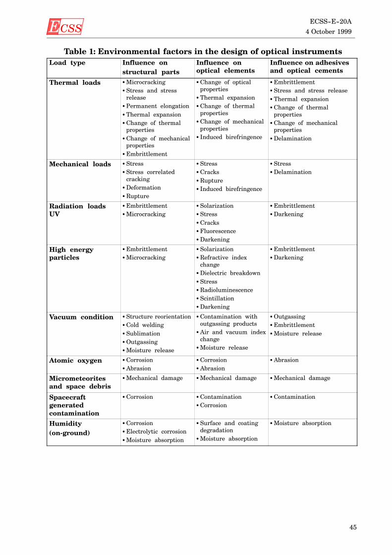
ECSS 4 October 1999
ECSS--E--20A
45
Table 1: Environmental factors in the design of optical instrumentsLoad type Influence on
structural partsInfluence onoptical elements
Influence on adhesivesand optical cements
Thermal loads SMicrocrackingS Stress and stressreleaseS Permanent elongationS Thermal expansionS Change of thermalpropertiesS Change of mechanicalpropertiesS Embrittlement
S Change of opticalpropertiesS Thermal expansionS Change of thermalpropertiesS Change of mechanicalpropertiesS Induced birefringence
S EmbrittlementS Stress and stress releaseS Thermal expansionS Change of thermalpropertiesS Change of mechanicalpropertiesSDelamination
Mechanical loads S StressS Stress correlatedcrackingSDeformationS Rupture
S StressS CracksS RuptureS Induced birefringence
S StressSDelamination
Radiation loadsUV
S EmbrittlementSMicrocracking
S SolarizationS StressS CracksS FluorescenceSDarkening
S EmbrittlementSDarkening
High energyparticles
S EmbrittlementSMicrocracking
S SolarizationS Refractive indexchangeSDielectric breakdownS StressS RadioluminescenceS ScintillationSDarkening
S EmbrittlementSDarkening
Vacuum condition S Structure reorientationS Cold weldingS SublimationSOutgassingSMoisture release
S Contamination withoutgassing productsS Air and vacuum indexchangeSMoisture release
SOutgassingS EmbrittlementSMoisture release
Atomic oxygen S CorrosionS Abrasion
S CorrosionS Abrasion
S Abrasion
Micrometeoritesand space debris
SMechanical damage SMechanical damage SMechanical damage
Spacecraftgeneratedcontamination
S Corrosion S ContaminationS Corrosion
S Contamination
Humidity(on-ground)
S CorrosionS Electrolytic corrosionSMoisture absorption
S Surface and coatingdegradationSMoisture absorption
SMoisture absorption
ECSS4 October 1999ECSS--E--20A
46
8.3 SafetySafety of personnel using optical instruments shall be according to IEC 60825.
8.4 VerificationThe requirements on optical systems shall be verified and the verification methodselected as per 4.6 of ECSS--E--10A. The corresponding verification tasks arespecified in 5.6 of ECSS--E--10A.
a. The performance requirements of 8.2.1 shall be verified by analysis and test.
b. The design requirements of 8.2.2 shall be verified by analysis.
c. The safety requirement of 8.3 shall be verified by analysis.
ECSS 4 October 1999
ECSS--E--20A
47
Annex A (normative)
EMC control plan - Document Requirements
Definition (DRD)
A.1 IntroductionThis document defines the approach, methods, procedures, resources and organ-ization to design, produce and verify a product to operate within its specified elec-tromagnetic environment and performance characteristics.
A.2 Scope and applicability
A.2.1 ScopeThis document requirements definition (DRD) establishes the data content re-quirements for the EMC control plan.
This DRD does not define format, presentation or delivery requirements for theEMC control plan.
A.2.2 ApplicabilityThis DRD is applicable to all projects using the ECSS Standards.
A.3 References
A.3.1 Glossary and dictionaryThis DRD uses terminology and definitions controlled by:
ECSS--P--001 Glossary of terms
ECSS--E--20 Space engineering -- Electrical and electronic
A.3.2 Source documentThis DRD defines the data requirements of an EMC control plan as controlled byECSS--E--20.
ECSS4 October 1999ECSS--E--20A
48
A.4 Terms, definitions and abbreviated terms
A.4.1 Terms and definitionsFor the purposes of this DRD the terms and definitions given in ECSS--P--001 andin ECSS--E--20 apply.
A.4.2 Abbreviated termsThe following abbreviations are used within this DRD.
Abbreviation Meaning
EMC Electromagnetic Compatibility
EMI Electromagnetic Interference
EED Electro-Explosive Device
SRD System Requirement Document
A.5 Description and purposeThe EMC control plan provides the instruction for conducting all activities re-lated to the management, the design requirements and the verification of theelectromagnetic compatibility of all items of equipment and subsystems of a pro-ject.
A.6 Application and interrelationshipThe document shall be prepared for each project, based on the system require-ment definition and the applicable electromagnetic specification.
It shall then apply to every item of equipment and subsystem in the project.
A.7 EMC control plan preliminary elements
A.7.1 TitleThis document shall be titled “[insert a descriptive modifier, e.g. name of the pro-ject] EMC control plan”.
A.7.2 Title pageThe title page for this document shall identify the project document identificationnumber, title of the document, date of release and release authority.
A.7.3 Contents listThe contents list shall identify the title and location of every clause and majorsubclause, figure, table and annex contained in the document.
A.7.4 ForewordA foreword shall be included in the document which describes as many of the fol-lowing items as are appropriate:
D identification of which organizational entity prepared the document;
D information regarding the approval of the document;
D identification of other organizations that contributed to the preparation ofthe document;
D a statement of effectivity identifying which other documents are cancelledand replaced in whole or in part;
D a statement of significant technical differences between this document andany previous document;
D the relationship of the document to other standards or documents.
ECSS 4 October 1999
ECSS--E--20A
49
A.7.5 IntroductionAn introduction may be included to provide specific information or commentaryabout the technical content.
A.8 Content
A.8.1 Scope and applicabilityThis clause shall be numbered 1 and shall describe the scope, applicability andpurpose of the EMC control plan
A.8.1.1 ScopeThis subclause shall be numbered 1.1 and shall contain the following statements:
“This EMC control plan defines the instructions for the [insert projectidentifier] project.
This EMC control plan is based on the requirements of the [insert projectSRD identifier].”
A.8.1.2 PurposeThis subclause shall be numbered 1.2 and shall contain the following statement:
“This EMC control plan defines the EMC programme management, thesystem level performance and design requirements, the subsystem andequipment EMI performance requirements and verification requirementsfor electro-explosive devices design and verification, EMC analysis andspacecraft level verification.”
A.8.2 ReferencesThis clause shall be numbered 2 and shall contain the following subclauses.
A.8.2.1 Normative referencesThis subclause shall be numbered 2.1 and shall contain the following statements:
“This document incorporates, by dated or undated reference, provisions fromother publications. These normative references are cited at appropriateplaces in the text and publications are listed hereafter. For dated references,subsequent amendments to or revisions of any of these apply to thisdocument only when incorporated in it by amendment or revision. Forundated references, the latest edition of the publication referred to applies.
[insert document identifier] [insert document title].”(Typically the SRD and some EMC standards may be quoted here.)
A.8.2.2 Informative referencesThis subclause shall be numbered 2.2 and shall contain the following statement:
“The following documents, although not a part of this EMC control plan,amplify or clarify its contents:
[insert document identifier] [insert document title]”
A.8.3 Terms, definitions and abbreviated termsThis clause shall be numbered 3 and shall contain the following subclauses.
A.8.3.1 Terms and definitionsThis subclause shall be numbered 3.1 and shall list any applicable project diction-ary or glossary, and all unusual terms or terms with a meaning specific to theEMC control plan, with the definition of each term.
If a project dictionary or glossary is applicable, insert the following sentence:

ECSS4 October 1999ECSS--E--20A
50
“The definitions of [insert title and identifier of applicable dictionaries orglossaries] apply to this document.”
Insert the following sentence:
“The following terms and definitions are specific to this document:
[insert term] [insert definition].”
A.8.3.2 Abbreviated termsThis subclause shall be numbered 3.2 and shall list all abbreviations used in theEMC control plan with the full spelled--out meaning or phrase for each abbrevi-ation.
A.8.4 Requirements to be verifiedThis clause shall be numbered 4 and shall list the requirements to be verified inthe EMC control plan.
The following list includes areas forwhich requirements shall be generated in theEMC control plan. This list is not exhaustive.
a. EMC program management:
S responsibilities of customer and supplier at all levels, lines and protocolsof communication, control of design changes;
S planning of the EMC control program: facilities and personnel requiredfor successful implementation of the EMC control program; methods andprocedures of accomplishing EMC design reviews and coordination;
S program schedules: Integration of EMC program schedule and mile-stones within the program development master schedule.
b. System level performance and design requirements:
S definition of electromagnetic and related environments;S definition of critical circuits;S allocation of design responses at system and subsystem and equipment
levels;S antenna-to-antenna interference reduction analysis and technique;S establishment of a controlled grounding scheme;S wiring (including shielding and shield termination and categorization)
practises;S electrical bonding;S material properties, effects of corrosion prevention and similar concerns
on bonding and general EMC issues;S design criteria for alleviating effects of spacecraft charging and other
electrification issues.c. Subsystem and equipment EMI performance requirements and verification:
S allocated EMI performance at the equipment level, including tailoredequipment level requirements. The control plan shall be the vehicle fortailoring limits and test methods;
S test results from subsystem and equipment level EMI tests shall be sum-marized. Any specification non-compliances judged to be acceptable shallbe described in detail and the justifying rationale presented.
d. Electro-Explosive Devices (EED):
S appropriate requirements (ISO 14304 -- in preparation);S design techniques;S verification.
ECSS 4 October 1999
ECSS--E--20A
51
e. EMC analysis:
S predictions of intra-system EMI and EMC based on expected or actualequipment and subsystem EMI characteristics;
S design of solutions for predicted or actual interference situations;f. Spacecraft level EMC verification:
Outline of system-level EMC test plan, including rationale for selection ofcritical circuits for safety margin demonstration and instrumentationtechniques for both critical and EED circuit sensitization.

ECSS4 October 1999ECSS--E--20A
52
(This page is intentionally left blank)
ECSS 4 October 1999
ECSS--E--20A
53
Annex B (normative)
Electromagnetic effects verification plan -
Document Requirements Definition (DRD)
B.1 IntroductionThis document defines the approach, methods, procedures to verify electromag-netic effects.
B.2 Scope and Applicability
B.2.1 ScopeThis document requirements definition (DRD) establishes the data content re-quirements for the electromagnetic effects verification plan (EMEVP).
This DRD does not define format, presentation or delivery requirements for theelectromagnetic effects verification plan.
B.2.2 ApplicabilityThis DRD is applicable to all projects using the ECSS Standards.
B.3 References
B.3.1 Glossary and dictionaryThis DRD uses terminology and definitions controlled by:
ECSS--P--001 Glossary of terms
ECSS--E--20 Space engineering -- Electrical and electronic
B.3.2 Source documentThis DRD defines the data requirements of an electromagnetic effects verificationplan as controlled by ECSS--E--20.
B.4 Terms, definitions and abbreviated terms
B.4.1 Terms and definitionsFor the purposes of this DRD the terms and definitions given in ECSS--P--001 andin ECSS--E--20 apply.
ECSS4 October 1999ECSS--E--20A
54
B.4.2 Abbreviated termsThe following abbreviations are used within this DRD.
Abbreviation Meaning
EMEVP Electromagnetic Effects Verification Plan
EMC Electromagnetic Compatibility
EMI Electromagnetic Interference
EED Electro-Explosive Device
B.5 Description and purposeThe electromagnetic effects verification plan provides the instruction for conduct-ing all activities required to verify that the effects of the electromagnetic environ-ment are compatible with the requirement of the project.
B.6 Application and interrelationshipThe document is prepared for each project, based on the system requirement de-finition and the applicable electromagnetic specification.
It then applies to every item of equipment and subsystem in the project.
B.7 EMEVP preliminary elements
B.7.1 TitleThis document shall be titled “[insert a descriptive modifier, e.g. name of the pro-ject] electromagnetic effects verification plan”.
B.7.2 Title pageThe title page for this document shall identify the project document identificationnumber, title of the document, date of release and release authority.
B.7.3 Contents listThe contents list shall identify the title and location of every clause and majorsubclause, figure, table and annex contained in the document.
B.7.4 ForewordA foreword shall be included in the document which describes as many of the fol-lowing items as are appropriate:
D identification of which organizational entity prepared the document;
D information regarding the approval of the document;
D identification of other organizations that contributed to the preparation ofthe document;
D a statement of effectivity identifying which other documents are cancelledand replaced in whole or in part;
D a statement of significant technical differences between this document andany previous document;
D the relationship of the document to other standards or documents.
B.7.5 IntroductionAn introduction may be included to provide specific information or commentaryabout the technical content.
ECSS 4 October 1999
ECSS--E--20A
55
B.8 Content
B.8.1 Scope and applicabilityThis clause shall be numbered 1 and shall describe the scope, applicability andpurpose of the electromagnetic effects verification plan.
B.8.1.1 ScopeThis subclause shall be numbered 1.1 and shall contain the following statements:
“This electromagnetic effects verification plan defines the instructions forthe [insert project identifier] project.
This electromagnetic effects verification plan is based on the requirementsof the [insert project EMC control plan identifier].”
B.8.1.2 PurposeThis subclause shall be numbered 1.2 and shall contain the following statement:
“This electromagnetic effects verification plan defines the plans to follow toselect EMC criteria and limits, all tests conditions including test facilities,personnel, tests set-up, instruments range.”
B.8.2 ReferencesThis clause shall be numbered 2 and shall contain the following subclauses.
B.8.2.1 Normative referencesThis subclause shall be numbered 2.1 and shall contain the following statements:
“This document incorporates, by dated or undated reference, provisions fromother publications. These normative references are cited at appropriateplaces in the text and publications are listed hereafter. For dated references,subsequent amendments to or revisions of any of these apply to thisdocument only when incorporated in it by amendment or revision. Forundated references, the latest edition of the publication referred to applies.
[insert document identifier] [insert document title].”(Typically the EMC control plan and some EMC standards may be quotedhere.)
B.8.2.2 Informative referencesThis subclause shall be numbered 2.2 and shall contain the following statement:
“The following documents, although not a part of this electromagnetic effectsverification plan, amplify or clarify its contents:
[insert document identifier] [insert document title]
B.8.3 Terms, definitions and abbreviated termsThis clause shall be numbered 3 and shall contain the following subclauses.
B.8.3.1 Terms and definitionsThis subclause shall be numbered 3.1 and shall list any applicable project diction-ary or glossary, and all unusual terms or terms with a meaning specific to theEMEVP, with the definition of each term.
If a project dictionary or glossary is applicable, insert the following sentence:
“The definitions of [insert title and identifier of applicable dictionaries orglossaries] apply to this document.”
ECSS4 October 1999ECSS--E--20A
56
Insert the following sentence:
“The following terms and definitions are specific to this document:
[insert term] [insert definition].”
B.8.3.2 Abbreviated termsThis subclause shall be numbered 3.2 and shall list all abbreviations used in theelectromagnetic effects verification plan with the full spelled--out meaning orphrase for each abbreviation.
B.8.4 Elements of the planThis clause shall be numbered 4 and shall list the requirements of the plan. Thefollowing list is not exhaustive:
a. methods to be used to select critical circuits, used to monitor conformance todegradation criteria and safety margins, shall have the method of selectiondefined;
b. procedures used for developing failure criteria and limits;
c. test conditions and procedures for all electronic and electrical equipment in-stalled in or associated with spacecraft and sequence for operations duringtests, including switching. An intra-system compatibility culprit/victim testmatrix shall be part of the test procedure;
d. implementation and application of test procedures which shall includemodesof operation and monitoring points for each subsystem or equipment;
e. use of approved results from laboratory interference tests on subsystems andequipment;
f. methods and procedures for data readout and analysis;
g. means of verifying design adequacy of spacecraft electrification;
h. means of simulating and testing electro-explosive subsystems and devices(EEDs);
i. verifying electrical power quality, andmethods formonitoring DCand AC (asapplicable) power busses;
j. test locations and descriptions of arrangements for simulating operationalperformance in cases where actual operation is impractical;
k. configuration of equipment and subsystemsmodes of operation to ensure vic-tim equipment and subsystems are tested inmost sensitive modes, while cul-prit equipment and subsystems are tested in noisiest mode(s);
l. details concerning frequency ranges, channels, and combinations to be spe-cifically tested such as image frequencies, intermediate frequencies, local os-cillator, transmitter fundamental and harmonically related frequencies.Subsystem susceptibility frequencies identified during laboratory testingshall be included;
m. personnel required, including customer and supplier personnel at all levels,quality representatives;
n. list of all required test equipment, including a description of unique EMC in-strumentation for stimulating and measuring electrical, electronic, andmechanical outputs of equipment and subsystems to bemonitored during thetest program.

ECSS 4 October 1999
ECSS--E--20A
57
Annex C (normative)
Electromagnetic effects verification report -
Document Requirements Definition (DRD)
C.1 IntroductionThis document defines the approach, methods, procedures to verify electromag-netic effects.
C.2 Scope and Applicability
C.2.1 ScopeThis document requirements definition (DRD) establishes the data content re-quirements for the electromagnetic effects verification report (EMEVR).
This DRD does not define format, presentation or delivery requirements for theelectromagnetic effects verification report.
C.2.2 ApplicabilityThis DRD is applicable to all projects using the ECSS Standards.
C.3 References
C.3.1 Glossary and dictionaryThis DRD uses terminology and definitions controlled by:
ECSS--P--001 Glossary of terms
ECSS--E--20 Space engineering -- Electrical and electronic
C.3.2 Source documentThis DRD defines the data requirements of an electromagnetic effects verificationreport as controlled by ECSS--E--20.
C.4 Terms, definitions and abbreviated terms
C.4.1 Terms and definitionsFor the purposes of this DRD the terms and definitions given in ECSS--P--001 andin ECSS--E--20 apply.
ECSS4 October 1999ECSS--E--20A
58
C.4.2 Abbreviated termsThe following abbreviations are used within this DRD.
Abbreviation Meaning
EMEVP Electromagnetic Effects Verification Plan
EMEVR Electromagnetic Effects Verification Report
EMC Electromagnetic Compatibility
EMI Electromagnetic Interference
EED Electro-Explosive Device
C.5 Description and purposeThe electromagnetic effects verification report provides the instruction for repor-ting all activities in relation with the verification of the effects of the electromag-netic environment.
C.6 Application and interrelationshipThe document is prepared for each project, based on the electromagnetic effectsverification plan.
It then applies to every item of equipment and subsystem in the project.
C.7 EMEVR preliminary elements
C.7.1 TitleThis document shall be titled “[insert a descriptive modifier, e.g. name of the pro-ject] electromagnetic effects verification report”.
C.7.2 Title pageThe title page for this document shall identify the project document identificationnumber, title of the document, date of release and release authority.
C.7.3 Contents listThe contents list shall identify the title and location of every clause and majorsubclause, figure, table and annex contained in the document.
C.7.4 ForewordA foreword shall be included in the document which describes as many of the fol-lowing items as are appropriate:
D identification of which organizational entity prepared the document;
D information regarding the approval of the document;
D identification of other organizations that contributed to the preparation ofthe document;
D a statement of effectivity identifying which other documents are cancelledand replaced in whole or in part;
D a statement of significant technical differences between this document andany previous document;
D the relationship of the document to other standards or documents.
C.7.5 IntroductionAn introduction may be included to provide specific information or commentaryabout the technical content.
ECSS 4 October 1999
ECSS--E--20A
59
C.8 Content
C.8.1 Scope and applicabilityThis clause shall be numbered 1 and shall describe the scope, applicability andpurpose of the electromagnetic effects verification report.
C.8.1.1 ScopeThis subclause shall be numbered 1.1 and shall contain the following statements:
“This electromagnetic effects verification report defines the instructions forthe [insert project identifier] project.
This electromagnetic effects verification report is based on the requirementsof the [insert project EMC control plan identifier and EMEVP].”
C.8.1.2 PurposeThis subclause shall be numbered 1.2 and shall contain the following statement:
“This electromagnetic effects verification report reports on the results of theapplication of the electromagnetic effects verification procedure, as requiredby the EMC control plan.”
C.8.2 ReferencesThis clause shall be numbered 2 and shall contain the following subclauses.
C.8.2.1 Normative referencesThis subclause shall be numbered 2.1 and shall contain the following statements:
“This document incorporates, by dated or undated reference, provisions fromother publications. These normative references are cited at appropriateplaces in the text and publications are listed hereafter. For dated references,subsequent amendments to or revisions of any of these apply to thisdocument only when incorporated in it by amendment or revision. Forundated references, the latest edition of the publication referred to applies.
[insert document identifier] [insert document title].”(Typically the EMC control plan, the EMEVP and some EMC standards maybe quoted here.)
C.8.2.2 Informative referencesThis subclause shall be numbered 2.2 and shall contain the following statement:
“The following documents, although not a part of this electromagnetic effectsverification report, amplify or clarify its contents:
[insert document identifier] [ insert document title]
C.8.3 Terms, definitions and abbreviated termsThis clause shall be numbered 3 and shall contain the following subclauses.
C.8.3.1 Terms and definitionsThis subclause shall be numbered 3.1 and shall list any applicable project diction-ary or glossary, and all unusual terms or terms with a meaning specific to theEMEVR, with the definition of each term.
If a project dictionary or glossary is applicable, insert the following sentence:
“The definitions of [insert title and identifier of applicable dictionaries orglossaries] apply to this document.”
ECSS4 October 1999ECSS--E--20A
60
Insert the following sentence:
“The following terms and definitions are specific to this document:
[insert term] [insert definition].”
C.8.3.2 Abbreviated termsThis subclause shall be numbered 3.2 and shall list all abbreviations used in theelectromagnetic effects verification report with the full spelled-out meaning orphrase for each abbreviation.
C.8.4 Elements of the reportThis clause shall be numbered 4 and shall include as a minimum:
a. identification of specific objectives, including applicable requirements andEMEVP references;
b. description of test article, including configuration and drawings and photo-graphs as appropriate;
c. description of any fixes or configuration changes to article resulting fromverification failures;
d. summary of results including an executive summary stating degree of con-formance to requirements;
e. description of any deviations from test facilities, analysis techniques or tools,and inspection aids in EMEVP;
f. description of any deviations from step-by-step procedures in EMEVP;
g. test set-up diagrams/photographs as appropriate;
h. list of test equipment, including calibration information, as appropriate;
i. recorded data or logs, including instrument readings, correction factors, andreduced results; methods of data reduction shall be described. If value of datahas been compromised due to test conditions, the reason and impact on re-sults shall be stated;
j. identification of ambient and other test conditions.
ECSS 4 October 1999
ECSS--E--20A
61
Bibliography
ISO 14302 Electromagnetic Compatibility Requirements, SpaceSystems (in preparation)
ISO 14304 Criteria for explosive systems and devices used on spacevehicle (in preparation)
MIL--STD--1541A Electromagnetic compatibility requirements for spacesystems
MIL--STD--1512 Electroexplosive subsystems, electrically initiated, de-sign requirements and test methods
JPL Publication 86--14 NASA Aerospace Battery Safety Handbook, G.Halpert,S.Subbarao & J.Rowlette
SPIE Vol. 2210 Optical design and technologies for space instrumenta-tion, R.H Csichy

ECSS4 October 1999ECSS--E--20A
62
(This page is intentionally left blank)
ECSS 4 October 1999
ECSS--E--20A
63
ECSS Document Improvement Proposal1. Document I.D.ECSS--E--20A
2. Document date4 October 1999
3. Document titleElectrical and electronic
4. Recommended improvement (identify clauses, subclauses and include modified text orgraphic, attach pages as necessary)
5. Reason for recommendation
6. Originator of recommendation
Name: Organization:
Address: Phone:Fax:E--mail:
7. Date of submission:
8. Send to ECSS Secretariat
Name:W. KriedteESA--TOS/QR
Address:P.O. Box 2992200 AG NoordwijkThe Netherlands
Phone: +31--71--565--3952Fax: +31--71--565--6839E--mail: [email protected]
Note: The originator of the submission should complete items 4, 5, 6 and 7.This form is available as a Word and Wordperfect--Template on internet under
http://www.estec.esa.nl/ecss/improve/

ECSS4 October 1999ECSS--E--20A
64
(This page is intentionally left blank)