eco catalog.indd
TRANSCRIPT

AC500-eCo and CP600-eCoPLCs, Control Panels, Engineering Suite
Product catalog

2 AC500-eCo and CP600-eCo Catalog

AC500-eCo and CP600-eCo Catalog 3
Table of Contents
Automation Builder ...........................................................................................................4
AC500-eCo PLC Overview .......................................................................................................................6
Ordering Data ................................................................................................................8
Technical Data ...............................................................................................................11
System Data ..................................................................................................................18
CP600-eCo HMI
Overview ........................................................................................................................20
Ordering Data ................................................................................................................21
Technical Data ...............................................................................................................21
Website ............................................................................................................................22
4 AC500-eCo and CP600-eCo Catalog
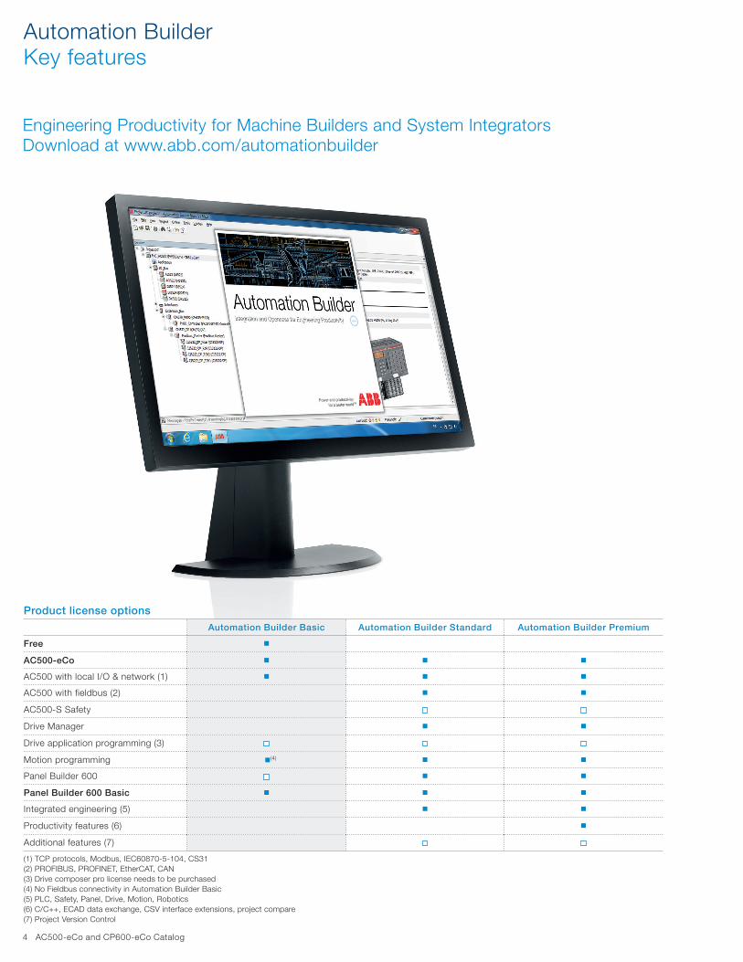
Automation BuilderKey features
Engineering Productivity for Machine Builders and System Integrators Download at www.abb.com/automationbuilder
Product license options
Automation Builder Basic Automation Builder Standard Automation Builder Premium
Free n
AC500-eCo n n n
AC500 with local I/O & network (1) n n n
AC500 with fieldbus (2) n n
AC500-S Safety
Drive Manager n n
Drive application programming (3)
Motion programming n(4) n n
Panel Builder 600 n n
Panel Builder 600 Basic n n n
Integrated engineering (5) n n
Productivity features (6) n
Additional features (7)
(1) TCP protocols, Modbus, IEC60870-5-104, CS31(2) PROFIBUS, PROFINET, EtherCAT, CAN(3) Drive composer pro license needs to be purchased(4) No Fieldbus connectivity in Automation Builder Basic(5) PLC, Safety, Panel, Drive, Motion, Robotics(6) C/C++, ECAD data exchange, CSV interface extensions, project compare(7) Project Version Control

AC500-eCo and CP600-eCo Catalog 5
Discover engineering productivity when engineering your discrete automation solutions.Automation Builder is ABB's integrated programming, main-tenance and simulation environment for PLCs, safety, robots, motion, drives and control panels.
Automation Builder combines the proven ABB tools RobotStudio, Drive Manager, Mint WorkBench, Panel Builder and succeeds Control Builder Plus.
The Automation Builder minimizes your efforts for project code and data administration. Improve your productivity with seamless engineering, common data storage, a single project archive, time-saving library blocks for device integration, and one common software installer.
Reduce engineering efforts and maintenance costs using easy-to-use libraries for wind, water, solar, drives, motion, robotics and safety applications.
Benefit from the simplicity of IEC 61131-3, PLCopen, C/ C++, RAPID and MINT programming languages.
Speed up your project with the powerful ECAD and MS EXCEL® interfaces of Automation Builder.
Simplified diagnostics and maintenance reduce downtime.Automation Builder is the perfect software suite for the configuration and programming of various ABB controller families in one single project.
Safe and restore your applications with a consistent joint backup.
Download Automation Builder from www.abb.com/automationbuilder.Familiarize with Automation Builder Premium using a 30 days test license.
After having tried and tested with your individual applications, you can use the free Automation Builder Basic or purchase the Automation Builder Standard or Premium.
Streamline and simplify your engineering process: Reduce risk and save time.
RiskCommissioningRiskControlRiskElectricalMechanical
Electrical
Control
Commissioning
Mechanical
Saved time
Reduced risk
Automation BuilderKey features

6 AC500-eCo and CP600-eCo Catalog
AC500-eCoKey features
– Up to 10 I/O modules connected to the CPU
– Digital I/O module with configurableI/Oavailable
High performance variant with large memory available
Comprehensive communication options:– Ethernet for communication andwebserverforuserdefinedvisualization
– Up to two serial ports available forI ⁄Oandcommunication
– Three different types of terminal blocks available
– IntegratedonboardI ⁄O– AC versions with integrated
power supply

AC500-eCo and CP600-eCo Catalog 7
SD-card adapter
COM1 USB
COM2 USBprogramming cable
SD-card
Terminal blocks
3 4
810
11
AC500-eCoKey features
AC500-eCo CPUs are expandable with up to 10 I/O modules. AC500-eCo CPUs with different performance levels are available.
6
5
74
3
9
2
11
8
10
1
Wall mounting
RS485 isolator for COM1
2
Adapter with COM27
9
Adapter with realtime clock
AC500-eCo CPUs are locally expandable with up to 10 I/O modules
1
Adapter with COM2 & realtime clock
5
6

8 AC500-eCo and CP600-eCo Catalog
AC500-eCo CPUs – 1 RS485 serial interface (2nd is optional) – Centrally expandable with up to 10 I/O modules – Optional SD card adapter for data storage and program backup – Variants with integrated Ethernet (Ethernet includes web server) – Minimum cycle time per instruction: Bit 0.08 µs, Word 0.1 µs, Float-point 1.2 µs.
Programmemory
Onboard I/Os
Relay /Transistor outputs
Integrated communication
Power supply
Terminal block required
Type Order code Weight(1 pce)
kB DI/DO/AI/AO 9 poles 11 poles kg
PM554: digital I/Os128 8 / 6 / – / – Transistor – 24 V DC 1 1 PM554-TP 1SAP120600R0001 0.300128 8 / 6 / – / – Relay – 24 V DC 1 1 PM554-RP 1SAP120700R0001 0.400128 8 / 6 / – / – Relay – 100-240 V AC 1 1 PM554-RP-AC 1SAP120800R0001 0.400128 8 / 6 / – / – Transistor Ethernet 24 V DC 1 1 PM554-TP-ETH 1SAP120600R0071 0.400
PM556: digital I/Os, 512 kB program memory512 8 / 6 / – / – Transistor Ethernet 24 V DC 1 1 PM556-TP-ETH 1SAP121200R0071 0.400
PM564: digital and analog I/Os (1)128 6 / 6 / 2 / 1 Transistor – 24 V DC 1 1 PM564-TP 1SAP120900R0001 0.300128 6 / 6 / 2 / 1 Relay – 24 V DC 1 1 PM564-RP 1SAP121000R0001 0.400128 6 / 6 / 2 / 1 Relay – 100-240 V AC 1 1 PM564-RP-AC 1SAP121100R0001 0.400128 6 / 6 / 2 / 1 Transistor Ethernet 24 V DC 1 1 PM564-TP-ETH 1SAP120900R0071 0.300128 6 / 6 / 2 / 1 Relay Ethernet 24 V DC 1 1 PM564-RP-ETH 1SAP121000R0071 0.400128 6 / 6 / 2 / 1 Relay Ethernet 100-240 V AC 1 1 PM564-RP-ETH-AC 1SAP121100R0071 0.400
PM566: digital and analog I/Os, 512 kB program memory (1)512 6 / 6 / 2 / 1 Transistor Ethernet 24 V DC 1 1 PM566-TP-ETH 1SAP121500R0071 0.400
Terminal blocks (9 and 11 poles) are necessary for each AC500-eCo. The terminal blocks must be ordered separately (see page 10).(1)AllanaloginputsonPM564andPM566canbeconfiguredasdigitalinputs.
AC500-eCoOrdering data
PM554
PM556
PM564
PM566

AC500-eCo and CP600-eCo Catalog 9
S500-eCo I/O modules – For central expansion of the AC500-eCo CPUs
AC500-eCoOrdering data
DI561
AI562
AX561
Digital I/O – DC:Channelscanbeconfiguredindividuallyasinputsoroutputs.
Number of Input signal Output type
Output signal Terminal block required
Type Order code Weight(1 pce)
DI/DO/DC 9 poles 11 poles kg8 / – / – 24 V DC – – 1 – DI561 1TNE968902R2101 0.1216 / – / – 24 V DC – – 1 1 DI562 1TNE968902R2102 0.128 / – / – 100-240 V AC – – 1 1 DI571 1TNE968902R2103 0.1516 / – / – 100-240 V AC – – 1 1 DI572 1SAP230500R0000 0.19– / 8 / – – Transistor 24 V DC, 0.5 A – 1 DO561 1TNE968902R2201 0.12– / 16 / – – Transistor 24 V DC, 0.5 A 1 1 DO562 1SAP230900R0000 0.16– / 8 / – – Relay 24 V DC, 120 /
240 V AC, 2 A– 1 DO571 1TNE968902R2202 0.15
– / 8 / – – Triac 100-240 V AC, 0.3 A 1 1 DO572 1TNE968902R2203 0.12– / 16 / – – Relay 24 V DC, 120 /
240 V AC, 2 A1 1 DO573 1SAP231300R0000 0.19
8 / 8/ – 24 V DC Transistor 24 V DC, 0.5 A 1 1 DX561 1TNE968902R2301 0.12
8 / 8/ – 24 V DC Relay 24 V DC, 120 / 240 V AC, 2 A
1 1 DX571 1TNE968902R2302 0.15
– / – / 16 24 V DC Transistor 24 V DC, 0.5 A 1 1 DC562 1SAP231900R0000 0.15
Terminal blocks (9 or 11 poles) are necessary for each S500-eCo I/O. The terminal blocks must be ordered separately (see page 10).
Analog I/O – Eachchannelcanbeconfiguredindividually – Resolution:
- AI561, AO561, AX561: 12 bits/11 bits + sign - AI562, AI563: 15 bits + sign.
Number of Input signal Output signal Terminal block required
Type Order code Weight(1 pce)
AI/AO 9 poles 11 poles kg4 / 0 ±2.5 V, ±5 V, 0...5 V,
0...10 V,0...20mA,4...20 mA
– 1 1 AI561 1TNE968902R1101 0.12
2 / 0 PT100, PT1000, Ni100, Ni1000, Resistance: 150 Ω,300Ω
– – 1 AI562 1TNE968902R1102 0.12
4 / 0 S, T, R, E, N, K, J, Voltage range: ±80 mV
– 1 1 AI563 1TNE968902R1103 0.12
0 / 2 – -10...+10V,0...20 mA,4...20 mA
– 1 AO561 1TNE968902R1201 0.12
4 / 2 ±2.5 V, ±5 V, 0...5 V, 0...10 V,0...20mA,4...20 mA
-10...+10V,0...20 mA,4...20 mA
1 1 AX561 1TNE968902R1301 0.13
Terminal blocks (9 or 11 poles) are necessary for each S500-eCo I/O. The terminal blocks must be ordered separately (see page 10).

10 AC500-eCo and CP600-eCo Catalog
AC500-eCoOrdering data
Positioning module – For central expansion of the AC500-eCo CPUs – TheFM562moduleprovidesPulseTrainOutputsfor2axes.Profilegeneratorintegrated.
Numberof axis
Input signal Output signal Terminal block required
Type Order code Weight(1 pce)
9 poles 11 poles kg2 4 digital inputs 24 V
(2 per axis)4 pulse outputsRS422 (2 per axis)
1 1 FM562 1SAP233100R0001 0.15
Terminal blocks (9 or 11 poles) are necessary for each S500-eCo I/O. The terminal blocks must be ordered separately (see page 10). Library PS552-MC-E is required for programming this module.
AccessoriesDescription Type Order code Weight
(1 pce)kg
SD Memory Card 2 GB needs the MC503 option MC502 1SAP180100R0001 0.020SD Memory Card adapter MC503 1TNE968901R0100 0.010Programming cable USB => RS485 Sub-D, 3 m TK503 1TNE968901R1100 0.400Programming cable USB => RS485 Terminal block, 3 m TK504 1TNE968901R2100 0.400RS485 isolator, Sub-D 9 poles / Terminal 5 poles for COM1 TK506 1SAP186100R0001 0.080Real time clock option board TA561-RTC (1) 1SAP181400R0001 0.007RS485 serial adapter COM2, pluggable screw terminal block included TA562-RS 1TNE968901R4300 0.007Combined Real Time Clock option with RS485 serial adapter COM2, pluggable screw terminal block, included
TA562-RS-RTC (1) 1SAP181500R0001 0.012
Wall Mounting Accessory for AC500-eCo CPU and S500-eCo I/O modules (100 pieces per case)
TA566 1TNE968901R3107 0.450
Set of accessories: 6 x plastic cover for option slot, 6 x 5 pole terminal block, 6 x 5 pole screw terminal blockfor COM2 serial interface.
TA570 1TNE968901R3203 0.090
Digital input simulator for onboard I/O of CPU, 6 x switch, 24 V DC TA571-SIM 1TNE968903R0203 0.040
(1) Standard battery CR 2032 has to be purchased separately.
TA562-RS-RTC
TA562-RS
TA561-RTC
TA570
FM562
TA565-9
TA564-11
TK506
TA563-9
Terminal blocks for S500-eCo I/O modules and AC500-eCo CPUsNumber of poles
Connection type Cable entry Type Order code Weight(1 pce)kg
9 Screw Side TA563-9 1TNE968901R3101 0.01711 Screw Side TA563-11 1TNE968901R3102 0.0209 Screw Front TA564-9 1TNE968901R3103 0.02611 Screw Front TA564-11 1TNE968901R3104 0.0359 Spring Front TA565-9 1TNE968901R3105 0.01611 Spring Front TA565-11 1TNE968901R3106 0.020
Only ABB terminal blocks must be used with AC500-eCo.
LibrariesFor Description Type Order code Weight
(1 pce)kg
all AC500 CPUs Motion Control library, Extended (1) PS552-MC-E 1SAP192100R0102 0.300
(1) Delivery includes single user license, software can be downloaded.
TA571-SIM

AC500-eCo and CP600-eCo Catalog 11
AC500-eCoTechnical data
AC500-eCo CPUsType PM554-TP PM554-RP PM554-RP-AC PM554-TP-ETH PM556-TP-ETHSupply voltage 24 V DC 100-240 V AC 24 V DCCurrent consumption on 24 V DC 100 V AC 240 V AC 24 V DC
Min. typ. (module alone) 0.06 A 0.08 A 0.02 A 0.012 A 0.07 A 0.07 AMax. typ. (I/Os) 0.18 A 0.22 A 0.2 A 0.11 A 0.19 A 0.19 A
Program memory 128 kB 512 kBIntegrated data memory 14 kB thereof 2 kB saved 130 kB thereof 2 kB saved
Web server's data for user RAM disk – 512 kB 1024 kBData buffering (of saved data) flash memoryReal-time clock (option with battery back-up) (1)
Program executionCyclical
Time controlled
Multi tasking no, 1 task + 1 interrupt task max.Interruption
User program protection by password
Cycle time for 1 instruction (minimum)Binary 0.08 µsWord 0.1 µsFloating 1.2 µsOnboard digital inputsChannels 8 (including 2 counter inputs)Signal voltage 24 V DCOnboard digital outputsChannels 6 (including 2 PWM outputs)Relay / Transistor Transistor Relay Relay Relay Transistor TransistorRated voltage 24 V DC 240 V AC 240 V AC 240 V AC 24 V DC 24 V DCNominal current per channel 0.5 A 2 A resistive 2 A resistive 2 A resistive 0.5 A 0.5 AOnboard analog outputsChannels -signal ranges -Onboard analog inputs
Channels -signal ranges -Max. number of centralized inputs/outputsMax. number of extension modules on I/O bus
up to max. 10
Digital inputs 320 + 8outputs 320 + 6
Analog inputs 160outputs 160
Internal interfacesCOM1
RS485
Sub-D connection
Programming, Modbus, ASCII
COM2 (option) (2)RS485
Terminal block
Programming, Modbus, ASCII
EthernetRJ45 –
Ethernet functions: Programming, Modbus TCP/IP, UDP/IP, integrated Web server, DHCP, FTP server, SNTP client
–
SMTP –
RUN/STOP switch
LED display for power, status and error
Approvals cULus, Class 1 Div 2, CE, EAC, RCM, KCC(3), ABS, BV, DNV, GL, LR, RINA, RMRS, ROHS
(1) Real-time clock requires optional TA561-RTC or TA562-RS-RTC and CR2032 battery (sold separately)(2) COM2 requires TA562-RS-RTC or TA562-RS.(3) Submitted

12 AC500-eCo and CP600-eCo Catalog
AC500-eCoTechnical data
AC500-eCo CPUsType PM564-TP PM564-RP PM564-RP-AC PM564-TP-ETH PM566-TP-ETH PM564-RP-ETH PM564-RP-ETH-ACSupply voltage 24 V DC 100-240 V AC 24 V DC 100-240 V ACCurrent consumption on 24 V DC 100 V AC 240 V AC 24 V DC 100 V AC 240 V AC
Min. typ. (module alone) 0.095 A 0.11 A 0.02 A 0.011 A 0.10 A 0.10 A 0.12 A 0.023 A 0.014 AMax. typ. (I/Os) 0.21 A 0.24 A 0.21 A 0.125 A 0.22 A 0.22 A 0.25 A 0.22 A 0.13 A
Program memory 128 kB 512 kB 128 kBIntegrated data memory 14 kB thereof 2 kB saved 130 kB thereof
2 kB saved14 kB thereof 2 kB saved
Web server's data for user RAM disk 512 kB 1024 kB 512 kBData buffering (of saved data) flash memoryReal-time clock (option with battery back-up) (1)
Program executionCyclical
Time controlled
Multi tasking no, 1 task + 1 interrupt task max.Interruption
User program protection by password
Cycle time for 1 instruction (minimum)Binary 0.08 µsWord 0.1 µsFloating 1.2 µsOnboard digital inputsChannels 6 (including 2 counter inputs)Signal voltage 24 V DCOnboard digital outputsChannels 6 (including 2 PWM outputs)Relay / Transistor Transistor Relay Relay Transistor Transistor Relay RelayRated voltage 24 V DC 240 V AC 240 V AC 24 V DC 24 V DC 240 V AC 240 V ACNominal current per channel 0.5 A 2 A resistive 2 A resistive 0.5 A 0.5 A 2 A resistive 2 A resistiveOnboard analog inputsChannels 2signal ranges 0...10 V / can be configured as digital input 24 V DCOnboard analog outputsChannels 1signal ranges 0...10 V / 0...20 mA / 4...20 mAMax. number of centralized inputs/outputsMax. number of extension modules on I/O bus
up to max. 10
Digital inputs 320 + 8outputs 320 + 6
Analog inputs 160 + 2outputs 160 + 1
Internal interfacesCOM1
RS485
Sub-D connection
Programming, Modbus, ASCII
COM2 (option) (2)RS485
Terminal block
Programming, Modbus, ASCII
EthernetRJ45 –
Ethernet functions: Programming, Modbus TCP/IP, UDP/IP, integrated Web server, DHCP, FTP server, SNTP client
–
SMTP
RUN/STOP switch
LED display for power, status and error
Approvals cULus, Class 1 Div 2, CE, EAC, RCM, KCC(3), ABS, BV, DNV, GL, LR, RINA, RMRS, ROHS
(1) Real-time clock requires optional TA561-RTC or TA562-RS-RTC and CR2032 battery (sold separately)(2) COM2 requires TA562-RS-RTC or TA562-RS.(3) Submitted

AC500-eCo and CP600-eCo Catalog 13
AC500-eCoTechnical data
Digital S500-eCo I/O modulesType DI561 DI562 DI571 DI572 DO561 DO562Supply voltage – – – – 24 V DC 24 V DCCurrent consumption on UP
Max. typ. (without load current) – – – – 0.005 A 0.005 A
Number of channels per moduleDigital inputs 8 16 8 (AC) 16 (AC) – –
outputs – – – – 8 16Configurable as Input or Output DC – – – – – –Relay / Transistor – – – – Transistor Transistor
Additional configuration of channels as:Fast Counter no not applicable
Digital inputsInput signal voltage 24 V DC 100-240 V AC – –Input time delay typically 4...8 ms typically 15 ms / 30 ms – –
Input current per channelAt Input voltage 24 V DC typically 5 mA – – – –
5 V DC typically 1 mA – – – –15 V DC > 2.5 mA – – – –30 V DC < 8 mA – – – –40 V AC – – < 3 mA – –164 V AC – – > 6 mA – –
Output currentNominal current per channel – – – – 0.5 A at UP = 24 V Maximum (total current of all channels) – – – – 4 A 8 AResidual current at signal state 0 – – – – < 0.5 mADemagnetization when switching off inductive loads
– – – – must be provided externally
Switching frequencyFor resistive load – – – – limited by CPU cycle timeFor inductive load – – – – max. 0.5 HzFor lamp load – – – – max. 11 Hz at max. 5 WShort circuit / overload proofness – – – – noOverload indication (I > 0.7 A) – – – – noOutput current limiting – – – – noProofness against reverse feeding of 24 V signals – – – – no
Contact ratingFor resistive load, max. – – – – – –For inductive load, max. – – – – – –For lamp load – – – – – –
Lifetime (switching cycles)Mechanical lifetime – – – – – –Lifetime under load – – – – – –
Maximum cable length for connected process signalsCable shielded 500 m
unshielded 300 m 150 m
Potential isolationPer module
Between the channels input – per group of 8 per group of 8 – –output – – – – – –
Voltage supply for the module's logic internal via I/O bus

14 AC500-eCo and CP600-eCo Catalog
AC500-eCoTechnical data
Digital S500-eCo I/O modulesType DO571 DO572 DO573Supply voltage 24 V DCCurrent consumption on UP
Max. typ. (without load current) 0.050 A – 0.050 A
Number of channels per moduleDigital inputs – – –
outputs 8 8 16Configurable as Input or Output DC – – –Relay / Transistor Relay triac (AC) Relay
Process voltageDC 24 V – –
Digital inputsInput signal voltage – – –Input time delay – – –
Input current per channelAt Input voltage 24 V DC – – –
5 V DC – – –15 V DC – – –30 V DC – – –
Output currentNominal current per channel 2 A (24 V DC / 120 V AC /
240 V AC, resistive load)0.3 A at 100...240 V AC
2 A (24 V DC / 120 V AC / 240 V AC, resistive load)
Maximum (total current of all channels) 2 x 8 A 2.4 A / 8 x 0.3 A max 10 A per group (20 A per module)
Residual current at signal state 0 – 1.1mArmsat132 V ACand 1.8 mA rms at 264 V AC
–
Demagnetization when switching off inductive loads
must be performed externally
Switching frequencyFor resistive load 1 Hz max. 10 Hz max. 1 Hz max.For inductive load – – –For lamp load 1 Hz max. 10 Hz max. 1 Hz max.Short circuit / overload proofness noOverload indication (I > 0.7 A) noOutput current limiting noProofness against reverse feeding of 24 V signals yes – yes
Contact ratingFor resistive load, max. 2 A 0.3 A 2 AFor inductive load, max. – – –For lamp load 200 W at 230 V AC
30 W at 24 V DC– 200 W at 230 V AC
30 W at 24 V DC
Lifetime (switching cycles)Mechanical lifetime 100 000 – 100 000Lifetime under load 100 000 at rated load – 100 000 at rated load
Maximum cable length for connected process signalsCable shielded 500 m
unshielded 150 m
Potential isolationPer module between outputs and logic between outputs and logicBetween the channels input – – –
output per group of 4 per group of 8Voltage supply for the module's logic internal via I/O bus
AC500-eCo and CP600-eCo Catalog 15
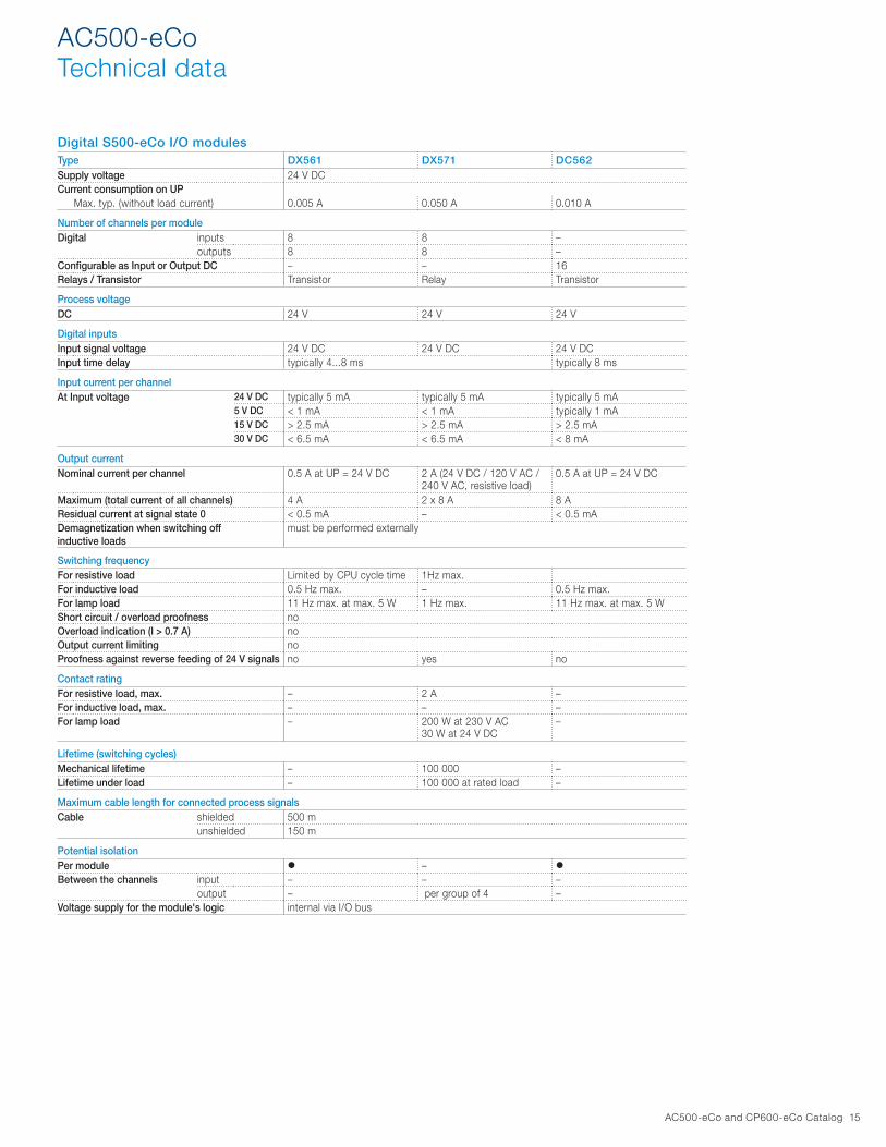
AC500-eCoTechnical data
Digital S500-eCo I/O modulesType DX561 DX571 DC562Supply voltage 24 V DCCurrent consumption on UP
Max. typ. (without load current) 0.005 A 0.050 A 0.010 A
Number of channels per moduleDigital inputs 8 8 –
outputs 8 8 –Configurable as Input or Output DC – – 16Relays / Transistor Transistor Relay Transistor
Process voltageDC 24 V 24 V 24 V
Digital inputsInput signal voltage 24 V DC 24 V DC 24 V DCInput time delay typically 4...8 ms typically 8 ms
Input current per channelAt Input voltage 24 V DC typically 5 mA typically 5 mA typically 5 mA
5 V DC < 1 mA < 1 mA typically 1 mA15 V DC > 2.5 mA > 2.5 mA > 2.5 mA30 V DC < 6.5 mA < 6.5 mA < 8 mA
Output currentNominal current per channel 0.5 A at UP = 24 V DC 2 A (24 V DC / 120 V AC /
240 V AC, resistive load)0.5 A at UP = 24 V DC
Maximum (total current of all channels) 4 A 2 x 8 A 8 AResidual current at signal state 0 < 0.5 mA – < 0.5 mADemagnetization when switching off inductive loads
must be performed externally
Switching frequencyFor resistive load Limited by CPU cycle time 1Hz max.For inductive load 0.5 Hz max. – 0.5 Hz max.For lamp load 11 Hz max. at max. 5 W 1 Hz max. 11 Hz max. at max. 5 WShort circuit / overload proofness noOverload indication (I > 0.7 A) noOutput current limiting noProofness against reverse feeding of 24 V signals no yes no
Contact ratingFor resistive load, max. – 2 A –For inductive load, max. – – –For lamp load – 200 W at 230 V AC
30 W at 24 V DC–
Lifetime (switching cycles)Mechanical lifetime – 100 000 –Lifetime under load – 100 000 at rated load –
Maximum cable length for connected process signalsCable shielded 500 m
unshielded 150 m
Potential isolationPer module –
Between the channels input – – –output – per group of 4 –
Voltage supply for the module's logic internal via I/O bus

16 AC500-eCo and CP600-eCo Catalog
AC500-eCoTechnical data
Analog S500-eCo I/O modulesType AI561 AO561 AX561 AI562 AI563Supply voltage 24 V DCCurrent consumption on UP
Max. typ. (without load current) 0.100 A 0.100 A 0.140 A 0.040 A 0.100 A
Number of channels per moduleAnalog inputs 4 – 4 2 4
outputs – 2 2 – –
Inputs, individually configurable-2.5…+2.5 V 11 bits + sign – – –-5…+5 V 11 bits + sign – – –-10…+10 V 11 bits + sign – – – – –0…5 V 12 bits – – –0…10 V 12 bits – – –0…20 mA, 4…20 mA 12 bits – – –RTD – – – 2 –
Pt100-50…+400 °C (2/3- wire) – – – –
Pt1000-50…+400 °C (2/3-wire) – – – –
Ni100 / Ni1000-50…+150 °C (2/3-wire) – – – –
Resistor 0…150 Ω/0...300 Ω – – – –Thermocouple Types J, K, T, N, S, E, R – – – –
Voltage -80...+80 mV – – – –
Outputs, individually configurable-10...+10 V – – –0…20 mA – – –4…20 mA – – –
Potential isolationPer module – – –

AC500-eCo and CP600-eCo Catalog 17
AC500-eCoTechnical data
FM562 positioning moduleTheFM562modulecontainsPulseTrainOutputsfor2axes.Profilegeneratorforsimplemotioncontroltasksareintegrated.TheRS422outputsallow a direct connection to Stepper- or Servo drives. Function blocks in PLCopen® motion control style allow the integration of the module in an application. These function blocks are contained in the library PS552-MC-E.
Type FM562
FunctionalityNumber of axis 2Digital inputs 2 digital inputs per axis
Function: for axis enable or limit switchPulse outputs Modes cw/ccw or pulse/direction
Built in profile generators
Data of the digital inputsSignal voltage 24 V DCInput current at 24 V DC typically 5 mAPotential isolation by groups of 2
Data of pulse outputsSignal RS422 (differential)Frequency range 0...250 kHzPotential isolation RS422 outputs of both axis in one group isolated against the inputs, the process voltage and the PLC CPU logic
Maximum cable length for digital inputsCable shielded 500 m
unshielded 300 m
Maximum cable length for pulse outputsCable shielded 300 m
unshielded 30 m
Process voltage UPNominal voltage 24 V DCCurrent consumption on UP typically 0.04 AReverse polarity protection
Potential isolationPer module
Voltage supply for the internal logic From UP / ZP with isolation

18 AC500-eCo and CP600-eCo Catalog
AC500-eCoSystem data
Environmental conditions
Process and supply voltages 24 V DC Process and supply voltage 24 V DC (-15 %, +20 % without ripple)
Absolute limits 19.2...30 V inclusive rippleRipple < 5 %Protection against reverse polarity 10 s
120 V AC Line voltage 120 V AC (-15 %, +10 %)Frequency 47...62.4 Hz / 50...60 Hz (-6 %, +4 %)
230 V AC Line voltage 230 V AC (-15 %, +10 %)Frequency 47...62.4 Hz / 50...60 Hz (-6 %, +4 %)
120–240 V AC Wide-range supplyLine voltage 102...264 V / 120..240 V (-15 %, +10 %)Frequency 47...62.4 Hz / 50...60 Hz (-6 %, +4 %)
Allowed interruptions of power supplyDC supply Interruption < 10 ms, time between 2 interruptions > 1 s, PS2AC supply Interruption < 0.5 periods, time between 2 interruptions > 1 s
Important: Exceeding the maximum power supply voltage (>30 V DC) for process or supply voltages could lead to unrecoverable damage of the system. The system could be destroyed. The creepage distances and clearances meet the requirements of the overvoltage category II, pollution degree 2. Forthesupplyofthemodules,powersupplyunitsaccordingtoPELVspecificationsmustbeused.
Climatic conditionsTemperature Operation 0...60 °C (horizontal mounting of modules)
0...40 °C (vertical mounting of modules and output load reduced to 50 % per group)Storage -40...+70 °CTransport -40...+70 °C
Humidity Without condensation Max. 95 %Air pressure Operation > 800 hPa / < 2000 m
Storage > 660 hPa / < 3500 m
Electromagnetic CompatibilityRadiated emission (radio disturbances) Acc. to IEC61000-6-4Conducted emission (radio disturbances) Acc. to IEC61000-6-4Electrostatic discharge (ESD) Acc. to EN 61000-4-2, zone B, criterion BFast transient interference voltages (burst) Acc. to EN 61000-4-4, zone B, criterion BHigh energy transient interference voltages (surge) Acc. to EN 61000-4-5, zone B, criterion BInfluence of radiated disturbances Acc. to IEC 61000-4-3, zone B, criterion AInfluence of line-conducted interferences Acc. to IEC 61000-4-6, zone B, criterion A
In order to prevent operating malfunctions, it is recommended, that the operating personnel discharge themselves prior to touching communication connectors or perform other suitable measures to reduce effects of electrostatic discharges. The connector of the I/O-Bus must not be touched during operation.
Mechanical dataWiring method Available types of terminal Spring terminals, screw terminalsDegree of protection IP 20 (if all terminal screws are tightened)Vibration resistance Acc. to IEC 61131-2Shock resistance Acc. to IEC 60068-2-27Assembly position Horizontal no derating
Vertical max. ambient temp. 40°C and output load reduced to 50% per groupAssembly on DIN rail Acc. to IEC 60715
DIN rail type 35 mm, depth 7.5 mm or 15 mmAssembly with screws Screw diameter 4 mm
Fastening torque 1.2 Nm
Main dimensions mm, inches
135 5.31”
75 2.96”
82 3.23”
135 5.31”
75 2.96”
34 1.34”

AC500-eCo and CP600-eCo Catalog 19
AC500-eCoSystem data
Environmental tests
Climatic and mechanical testsStorage Cold withstand test IEC 60068-2-1 Test Ab: cold withstand test -40 °C / 16 h
Dry heat withstand test IEC 60068-2-2 Test Bb: dry heat withstand test +70 °C / 16 hHumidity Damp heat test IEC 60068-2-30 Test Db: Cyclic (12 h / 12 h)
Damp-Heat Test 55 °C, 93 % r. H. / 25 °C, 95 % r. H., 2 cyclesInsulation Test Acc. to IEC 61131-2Vibration resistance DIN rail mounting all three axes
5...11.9 Hz, continuous 3.5 mm 11.9…150 Hz, continuous 1 g
With SD Memory Card inserted 15…150 Hz, continuous 1 gShock resistance DIN rail mounting IEC 60068-2-27: all 3 axes 15 g, 11 ms, half-sinusoidal
EMC immunity testsElectrostatic discharge (ESD) Electrostatic voltage in case of
air discharge8 kV
Electrostatic voltage in case of contact discharge
6 kV
Fast transient interference voltages (burst)
Supply voltage units (AC, DC) 2 kVDigital inputs/outputs (24 V DC) 2 kVDigital inputs/outputs (120/230 V AC) 2 kVAnalog inputs/outputs 1 kVCS31 system bus 2 kVSerial RS-485 interfaces (COM) 2 kVEthernet 1 kVI/O supply, DC-out 1 kV
High energy transient interference voltages (surge)
Power supply AC 2 kV CM (1) / 1 kV DM (2)Power supply DC 1 kV CM (1) / 0.5 kV DM (2)DC I/O supply, add. DC-supply-out 0.5 kV CM (1) / 0.5 kV DM (2)Buses, shielded 1 kV CM (1)AC-I/O unshielded 2 kV CM (1) / 1 kV DM (2)I/O analog, I/O DC unshielded 1 kV CM (1) / 0.5 kV DM (2)
Influence of radiated disturbances Test field strength 10 V/mInfluence of line-conducted interferences
Test voltage 3V zone B, 10 V is also met.
(1) CM = Common Mode.(2) DM = Differential Mode.

20 AC500-eCo and CP600-eCo Catalog
– Plastic Housing – Front protection IP66– Engineering software Panel
Builder 600 Basic integrated in Automation Builder Basic
–Improvedflexibilityandintegration–ConfigurationwithPanelBuilder600Basicfor
clear tailor made visualization.
– Brilliant colored display – Free reusable 3D graphic elements
(Widgets) – Import tags from PLC, drives, motion
controller and robots configuration within Automation Builder Basic
CP600-eCoKey features
– Slim design for easy installation even in compact spaces

AC500-eCo and CP600-eCo Catalog 21
CP607
CP600-eCo control panelsDisplay size
Resolution Type Order code Weight (1 pce)
pixels kg4.3" 480 x 272 for PB610-B Panel Builder 600 BASIC applications CP604 1SAP504100R0001 0.4007.0" 800 x 480 for PB610-B Panel Builder 600 BASIC applications CP607 1SAP507100R0001 0.60010.1" 1024 x 600 for PB610-B Panel Builder 600 BASIC applications CP610 1SAP510100R0001 1.000
Communication cables (connection control panel <–> PLC)Description Type Order code Weight (1
pce)kg
Communication cable RS485: CP600(-eCo) - AC500-eCo TK682 1SAP500982R0001 0.130
CP600-eCo Ordering data
Type CP604 CP607 CP610Application control panels for PB610-B Panel Builder 600 Basic applicationsDisplayExact display size diameter 4.3" widescreen 7" widescreen 10.1" widescreenResolution 480 x 272 pixels 800 x 480 pixels 1024 x 600 pixelsDisplay type, colors TFT-LCD, 65536 colorsTouch screen material glass covered by plastic filmTouch screen type analog restitive, 4 wiresBacklight type, life LED, 20 000 h typ at 25 °CBrightness 150 cd/m² 200 cd/m²HousingProtection class front, rear IP66, IP20Front side material PlasticReverse side material PlasticSystem resourcesProcessor type ARM 3352Operating system, version Linux V3Application memory for HMI projects of 30 MB in total plus 30 MB for fontsInterfacesEthernet ports, number, type 1 - 10/100 MbitUSB Host ports number, type 1 - ver. 2.0Serial ports number, type 1 - RS-232/-485/-422 software configurableAdditional ports number, type noneCard slot number, type nonePower supply voltage nominal, tolerance
24 V DC, 18…32 V DC
Current consumption at nominal voltage
0.1 A 0.15 A 0.25 A
Battery type Supercapacitor, 72 h at 25 °CWeight 0.4 kg 0.6 kg 1.0 kgFaceplate dimensions (L x H) 147 mm x 107 mm 187 mm x 147 mm 282 mm x 197 mmFaceplate depth 5 mm 6 mmHousing depth 29 mmCutout dimensions (L x H) 135 mm x 96 mm 176 mm x 136 mm 271 mm x 186 mmEnvironmental conditionsOperating temperature range 0…50 °COperating humidity range 5…85 % relative humidity, non-condesingStorage temperature range -20…+70 °CStorage humidity range 5…85 % relative humidity, non-condesingApprovals cULus, CE, EAC(1), RCM, KCC(1), ROHS(1) Planned
Technical data

22 AC500-eCo and CP600-eCo Catalog
PLC Automation product familyPLC Automation website – online tools
The www.abb.com/plc website is a mine of information on our products and documentation.

AC500-eCo and CP600-eCo Catalog 23
US district sales offices
ARIZONA PHOENIX 4211 S. 43RD PLACE PHOENIX, AZ 85040 PHONE: 602-470-0407 FAX: 602-470-0464
ARKANSAS CLARKSVILLE 706 WEST MAIN STREET CLARKSVILLE, AR 72830 PHONE: 479-754-9108 FAX: 479-754-9205
CALIFORNIA LOS ANGELES 6480 FLOTILLA STREET COMMERCE, CA 90040 PHONE: 323-724-6771 FAX: 323-721-5859
HAYWARD 21056 FORBES STREET HAyWARD, CA 94545 PHONE: 510-785-9900 FAX: 510-785-9910
COLORADO DENVER 3855 FOREST STREET DENVER, CO 80207 PHONE: 303-623-0127 FAX: 303-595-3772
CONNECTICUT WALLINGFORD 65 SOUTH TURNPIKE ROAD WALLINGFORD, CT 06492 PHONE: 203-269-1354 FAX: 203-269-5465
FLORIDA TAMPA / PUERTO RICO / VIRGIN ISLANDS 3906 EAST 11TH AVENUE TAMPA, FL 33605 PHONE: 813-248-5078 FAX: 813-241-9514
GEORGIA ATLANTA 62 TECHNOLOGy DRIVE ALPHARETTA, GA 30005 PHONE: 770-772-7000 FAX: 770-772-7200
ILLINOIS CHICAGO 340 REMINGTON BOULEVARD BOLINGBROOK, IL 60440 PHONE: 630-296-1400 FAX: 630-226-9420
INDIANA INDIANAPOLIS 5835 DECATUR BLVD INDIANAPOLIS, IN 46241 PHONE: 317-857-6019 FAX: 317-830-8131
IOWA DES MOINES 6243 NE INDUSTRy DRIVE DES MOINES, IA 50313 PHONE: 515-263-6929 FAX: 515-263-6515
KANSAS KANSAS CITY 9810 INDUSTRIAL BLVD. LENEXA, KS 66215 PHONE: 816-587-0272 FAX: 816-587-3735 MARYLAND BALTIMORE 7071A DORSEy RUN ROAD ELKRIDGE, MD 21075 PHONE: 410-579-2135 FAX: 410-579-2677
MASSACHUSETTS BOSTON 6 PULLMAN STREET WORCESTER, MA 01606 PHONE: 508-854-0708 FAX: 508-854-0291
MICHIGAN DETROIT 5993 PROGRESS DRIVE STERLING HEIGHTS, MI 48312 PHONE: 586-978-9800 FAX: 586-978-9969
MINNESOTA MINNEAPOLIS 13098 GEORGE WEBER DR SUITE #400 ROGERS, MN 55374 PHONE: 763-428-3633 FAX: 763-428-4551
MISSOURI ST. LOUIS 4761 EARTH CITy EXPRESSWAy BRIDGETON MO 63044 PHONE: 314-373-3032 FAX: 314-373-3038
NEW YORK AUBURN ONE ELLIS DRIVE AUBURN, Ny 13021 PHONE: 315-255-3403 FAX: 315-253-9923
NORTH CAROLINA GREENSBORO 1220 ROTHERWOOD ROAD GREENSBORO, NC 27406 PHONE: 336-272-6104 FAX: 336-273-6628
OHIO CINCINNATI 2929 CRESCENTVILLE ROAD WEST CHESTER, OH 45069 PHONE: 513-771-2600 FAX: 513-772-2219
OHIO CLEVELAND 8929 FREEWAy DRIVE MACEDONIA, OH 44056 PHONE: 330-468-4777 FAX: 330-468-4778
OKLAHOMA TULSA 9925 EAST ADMIRAL PLACE TULSA, OK 74116 PHONE: 918-366-9320 FAX: 918-366-9338
OREGON PORTLAND 16201 SE 98TH AVENUE CLACKAMAS, OR 97015 PHONE: 503-691-9010 FAX: 503-691-9012
PENNSYLVANIA PHILADELPHIA 103 CENTRAL AVENUE, SUITE 400B MT. LAUREL, NJ 08054 PHONE: 856-840-8011 FAX: 856-840-0811
PITTSBURGH 159 PROMINENCE DRIVE NEW KENSINGTON, PA 15068 PHONE: 724-889-0092 FAX: 724-889-0094
TENNESSEE MEMPHIS 4000 WINCHESTER ROAD, SUITE 1 MEMPHIS, TN 38118 PHONE: 901-365-2020 FAX: 901-365-3914
TEXAS DALLAS 2920 114TH STREET SUITE 100 GRAND PRAIRIE, TX 75050 PHONE: 214-634-7271 FAX: 214-634-8874
HOUSTON 10355 W. LITTLE yORK ROAD SUITE 300 HOUSTON, TX 77041 PHONE: 281-977-6500 FAX: 281-977-6510 UTAH SALT LAKE CITY 2230 SOUTH MAIN STREET SALT LAKE CITy, UT 84115 PHONE: 801-832-0127 FAX: 801-832-8911
WISCONSIN MILWAUKEE 1960 SOUTH CALHOUN ROAD NEW BERLIN, Wl 53151 PHONE: 262-784-5940 FAX: 262-784-1215

Contact us
MO
TIO
N-P
HP
B03
U-E
N
RE
VA E
ffec
tive
07/
19/2
016
ABB Inc. Discrete Automation & MotionDrives and Controls16250 W. Glendale Drive New Berlin, WI 53151 USA Phone: (800) 752-0696
www.abb.com/plc
NoteWe reserve the right to make technical changes or modify the contents of this document without prior notice.
ABB does not accept any responsibility whatsoever for potential errors or possible lack of information in this document.
We reserve all rights in this document and in the subject matter and illustrations contained therein. Any reproduction, disclosure to third parties or utilization of its contents – in whole or in parts – is forbidden without prior written consent of ABB.
Copyright © 2016 ABBAll rights reserved
www.abb.com/automationbuilder
www.abb.com/drives