ecn 4: new standard for high temporal dbi extinction imaging westlye.pdf · ecn 4: new standard for...
TRANSCRIPT

ECN 4: New standard for high temporal DBI extinction imaging
*Fredrik Ree Westlye(1) , Keith Penney (2), Scott Skeen (2), Julien Manin (2), Lyle Pickett (2) and Anders Ivarsson (1)
Abstract: An optical setup has been developed for diffused back-illumination imaging of liquid and soot extinction with high temporal capabilities. It has been specifically designed to isolate attenuation by absorption/scattering from light displacement by refractive gradients through a heated and pressurized environment. The design criteria have been determined from a conceptual description of beam-steering effect on quantification using simple ray tracing. These criteria are used to optimize for collection efficiency for high temporal capabilities. The improvements observed show that beam-steering effects on quantification is suppressed down to within the noise of the camera, thereby higher sensitivity and accuracy of soot extinction and liquid penetration measurements is achieved.
1 Department of Mechanical Engineering, Technical University of Denmark, Nils Koppels Alle Bld. 403, 2800 Kgs. Lyngby 2 Sandia National Laboratories, P.O. Box 969, Livermore, CA 94550, USA

ECN 2/11 September 2015
Previous DBI extinction imaging setup
• Quantitative soot volume fraction and qualitative liquid penetration measurements at high temporal resolution
• Soot extinction spray A std conditions. 630nm LED old DBI setup
• Liquid penetration spray A std conditions w/ 0% O2. 450nm LED old DBI setup

ECN 3/11 September 2015
Eliminating beam-steering
• Laser extinction requires wide collection angle to account for beam steering
• Image extinction requires wide angular distribution of the light to suppress beam steering
12⁰ full angle

ECN 4/11 September 2015
Refracting media can have a mix of many interactions with the incident light
4. Lensing effect (modifying focus/expansion)
1. Snell effect (modifying effective focal length)
2. Oblique Snell effect (Translation of the collection cone)
1. And 2. Spatial homogeneity of illumination across the
source
How to make undesired refraction effects
invisible:
Eliminating beam-steering
3. Even angular distribution wider than the collection angle
4. Cannot be corrected with diffused lighting
3. Slanted Snell effect (shifting the optical axis)

ECN 5/11 September 2015
Dimensioning DBI setup • Collection efficiency is important to promote high temporal
resolution capabilities
• Spreading angle of large engineered diffuser should be 1.5 time the collection angle
• Large collimated beam needed for diffuser to work optimally

ECN 6/11 September 2015
Measuring angular distribution
• 1D measurement
• 2D measurement
Collection efficiency as a function of angular
distribution
• Ray tracing
• Old setup • New setup

ECN 7/11 September 2015
Camera issues
• Fixed pattern noise is affected by the camera readout
• Correction brings dark up to
• Noise level restored after one dark frame
• Correction brings down to
KL↓
KL↑
− ln𝐼∗
𝐼0< −ln
𝐼
𝐼0
− ln𝐼∗
𝐼0> −ln
𝐼
𝐼0

ECN 8/11 September 2015
New DBI setup performance • Quantification is affected when beam-steering effects
introduce erroneous extinction
• Beam-steering effects smear out the sharp contrasts of the dense liquid vapor boundary
Pre
vio
us
New
P
revi
ou
s N
ew

ECN 9/11 September 2015
Checklist
• Report optical arrangement with distances, components and sizes
• Measure lighting characteristics with either 1D or 2D arrangement
Recommendations: 1. Angular distribution should be chosen to be 1.5 times
the collection angle and be homogenous across the image plane.
2. Spatial intensity should not fall more than 20% from the center to the periphery of the image plane.
• Report camera corrections made in post-processing and camera software corrections used

ECN 10/11 September 2015
Summary • The need for a new standard DBI setup is realized • The effect of beam-steering when spatially resolving extinction
measurements is systematically identified • From these effects, the lighting criteria for a new DBI setup are
established • A DBI setup dimensioned wrt ideal lighting and high temporal
resolution capabilities, is proposed • Issues with the high speed camera when performing high temporal
extinction imaging are addressed • The performance of the setup reveals significant improvement in
suppressing beam-steering while maintaining high temporal capabilities
• Sensitivity of extinction imaging measurements is increased and errors associated with beam-steering are suppressed within the noise of the measurement

ECN 4: Spray C and D liquid and vapor penetration
*Fredrik Ree Westlye(1) , Scott Skeen (2), Julien Manin (2), Lyle Pickett (2) and Anders Ivarsson (1) 1 Department of Mechanical Engineering, Technical University of Denmark, Nils Koppels Alle Bld. 403, 2800 Kgs. Lyngby 2 Sandia National Laboratories, P.O. Box 969, Livermore, CA 94550, USA
Abstract: Liquid and vapor penetration measurements are performed on a cavitating and non-cavitating automotive fuel injector (Spray C and D). The measurements are performed simultaneously using DBI and Mie scattering to image liquid phase and focused shadowgraph to image vapor phase in a dual line of sight accessible constant volume combustion vessel. The aim is visualize qualitatively the effect of cavitation on fuel spray characteristics. The experiments were performed under non-reacting and reacting Spray A std conditions. Results show that vapor phase penetrates faster and liquid phase longer for non-cavitating nozzle. The main reason being that the spray angle is wider for cavitating nozzle. There are some uncertainties as to what causes a wider spray angle and if it is cavitation related, as there are several other factors that may be responsible for this phenomena. CFD modelling can help answer questions about the origin of the wider spray angle.

ECN 12/11 September 2015
Break-up of liquid sprays
• Primary break-up: Stripping of ligaments and droplets from the in tact liquid core
• Secondary break-up: formation of spherical droplets.
• These break-up processes are confined close to the nozzle exit.
• Studies have shown that instabilities caused by cavitation within the nozzle, greatly promotes this break-up process.
Vapor

ECN 13/11 September 2015
Spray C and D Nozzles Spray C 210037
Spray D 209134
Mass 50.75mg/inj
Duration 2.5ms
Mass 43.2mg/inj
Duration 2.5ms
Minimum
diameter the same
d =0.186mm min
K-factor 0
d=0.2mm
K-factor 1.5
d=0.18

ECN 14/11 September 2015
Experimental methods
• High speed jet penetration measurements with focused shadowgraph technique
• High speed liquid penetration measurements with new standard DBI technique
• Liquid penetration measurements with Mie scatter technique at 90 degree solid angle
• All measurements were made simultaneously for every injection event
• Results are based on 10 injections with each nozzle at the standard reacting and non-reacting Spray A condition

ECN 15/11 September 2015
Experimental setup
Experimental setup

ECN 16/11 September 2015
D
C
C
D D
C
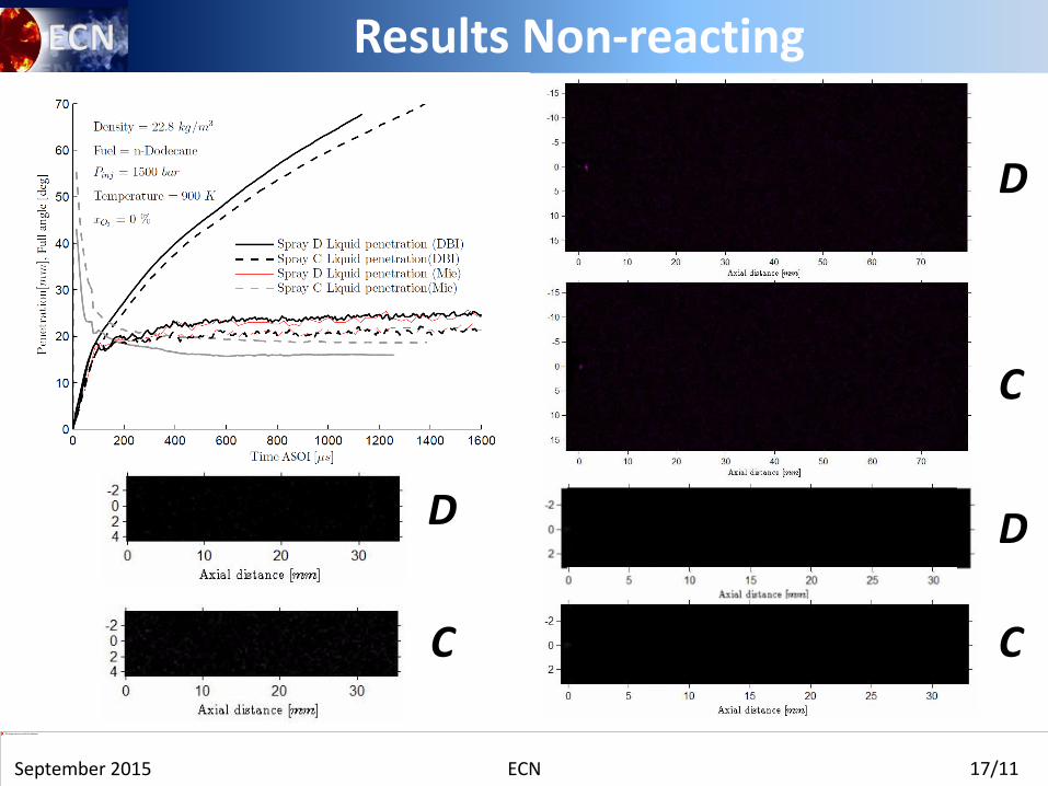
Results Non-reacting
ECN 17/11 September 2015
Results Non-reacting
D
C
C
D D
C

ECN 18/11 September 2015
Width of liquid spray
• Liquid/vapor boundary is wider and more deformed closer to the nozzle for Spray C
• Oscillations of the boundary are stochastic and show no distinct frequency
• Width of spray correlates with magnitude of oscillations at the boundary
• Onset of boundary instability closer to the nozzle for Spray C
• Spray C looks to have a virtual origin further from the nozzle

ECN 19/11 September 2015
Effect of cavitation
• Mixing based liquid length model accurately predicts the difference in liquid length
• Spray angle and contraction area source of difference in liquid penetration
• Is the difference cavitation related?
• CFD modelling of internal flow and liquid penetration can help answer these questions
• Spray C geometry is slightly diverging • Lower effective diameter also
promotes divergent flow • Difference may be due to
mismatched mass flow

ECN 20/11 September 2015
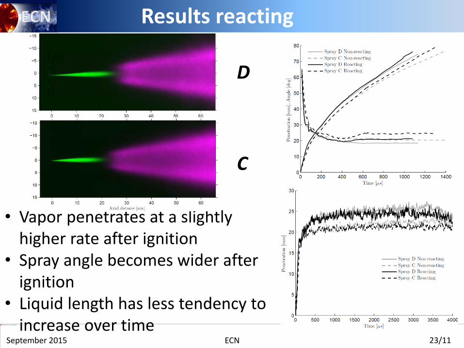
Results reacting
• Vapor penetrates at a slightly higher rate after ignition
• Spray angle becomes wider after ignition
• Liquid length has less tendency to increase over time
D
C

ECN 21/11 September 2015
Sandia & CMT data
• Large deviation between liquid penetration for both C and D nozzles
• Liquid length increases more with time for CMT measurements
• Vapor penetration measurements are similar

ECN 22/11 September 2015
Summary
• Liquid and vapor penetration measurements have been performed simultaneously with Spray C and D.
• Good agreement between DBI and Mie liquid penetration measurements.
• Differences between Spray C and D are mostly caused by difference in spray angle, and it is uncertain as to why Spray C is wider.
• Reacting measurements show that thermal expansion slightly accelerates vapor penetration and liquid penetration does not increase over time due to hotter entrained gases
• More work needed in the comparison between institutions as large deviations seem to stem from differences in nozzles
ECN 23/11 September 2015
Results reacting
• Vapor penetrates at a slightly higher rate after ignition
• Spray angle becomes wider after ignition
• Liquid length has less tendency to increase over time
D
C

ECN 24/11 September 2015
Components and function • High speed camera • State of the art LED driver
technology
• Optics promoting high collection efficiency
Photron SA-X2
Sandia 614 LED driver
Engineered diffuser
Band-pass filter
TIR LED collimator
Neutral density
filter
• Filtering

ECN 25/11 September 2015
Camera characterization
• High speed camera sensors are sensitive to ambient conditions and operation characteristics
• Pixel response curve needs to be corrected for
𝐾𝐿 = −ln𝐼
𝐼0

ECN 26/11 September 2015
Dimensioning DBI setup • Collection efficiency is important to promote high temporal
resolution capabilities
• Spreading angle of final diffuser should be as narrow as possible
• Diffusing angle should be chosen so as to not overfill the Fresnel lens