ecmc skilled nursing facility - penn state college of ... report... · ecmc skilled nursing...
TRANSCRIPT

Brian Brunnet | Architectural Engineering | Structural Option
Class:
Subject:
Faculty Consultant:
Submitted:
AE 481W
Technical Report 2
Dr. Ali Memari
October 19th
, 2011
ECMC Skilled Nursing Facility
Architectural Engineering Senior Thesis 2011

Page 2 of 45
Brian Brunnet | Architectural Engineering | Structural Option
Table of Contents Executive Summary ................................................................................................................... 3
Introduction ................................................................................................................................ 4
Architectural Overview ............................................................................................................... 5
Structural Systems Overview ..................................................................................................... 6
Foundation System................................................................................................................. 6
Floor System .......................................................................................................................... 7
Lateral System ....................................................................................................................... 8
Design Codes and Standards .................................................................................................... 9
Material Properties ....................................................................................................................10
Design Loads ............................................................................................................................11
Floor Systems ...........................................................................................................................12
Composite Beam & Girder System (Existing) ........................................................................12
Non-Composite Steel Framing System ..................................................................................14
Hollow Core Planks on Steel Framing ...................................................................................16
One-Way Post-Tensioned Flat Plate System .........................................................................18
Impact on Lateral System .........................................................................................................19
Post Tensioned and Hollow Core Plank Systems ..................................................................19
Composite and Non-Composite Systems ..............................................................................19
Foundations ..........................................................................................................................19
Systems Comparison ................................................................................................................20
Final Summary ..........................................................................................................................22
Appendices ...............................................................................................................................23
Appendix A: Framing Plan & Elevations ................................................................................23
Appendix B: Composite Steel Analysis (existing structure) ...................................................26
Appendix C: Non-Composite Steel Design ...........................................................................31
Appendix D: Post-Tensioned Design ....................................................................................36
Appendix E: Hollow Core Plank Design ................................................................................42

Page 3 of 45
Brian Brunnet | Architectural Engineering | Structural Option
Executive Summary
The purpose of Technical Report 2 is to explore the strength, serviceability, weight,
cost, and aesthetic features between the existing floor system at ECMC Skilled Nursing
Facility and three other different types of floor systems. Using hand calculations and
current industry standards such as ASCE 7, the AISC Steel Construction Manual, and
the ACI Building Code Requirements, each system will be evaluated and tested for
viability as a floor system alternative. The existing floor system consists of a 5¼” thick
LWC composite slab with composite steel beams and girders. The three systems
designed in this report include:
Non-Composite Steel Framing with Non-Composite Steel Deck
One-way Post Tensioned Concrete Flat Plate
Precast Hollow core Plank on Steel Girders
The design of the non-composite steel system results in 4” concrete topping on 2”
Vulcraft 2C22 non-composite deck. The framing is W18x35 infill beams spanning 29’-2”
with W21x48 girders spanning 26’-0”. This is a simple system to design and nearly
similar in deck weight, however because of the lack of composite action, the beams and
girders must be larger in section to support the full stresses involved. This system does
have the ability to be cored without receiving any significant structural strength issues.
This system lacks in adequate fireproofing and would need either a spray-on fire
protection or fire resistive drop ceiling. This system is relatively uneconomical and with
an existing system using composite action, it was deemed as an unacceptable choice.
An 8” thick LWC slab using tendons composed of (12) 0.196” diameter prestressing
wires resulted from the post tensioned floor system design. This post tensioned slab
system weighed more than the composite system due to an increased slab thickness;
however, it had the least system depth due to the absence of infill beams or girders.
The cost of the system was also the lowest of the four. The only issues found with the
PT system are that the slab cannot be easily cored for any future changes, and it
increases the difficulty to construct the post tensioned slab system due to additional
details. The benefits mainly outweigh the flaws, making this system a viable alternative.
Using design data sheets from Nitterhouse Concrete Products, a hollow core plank
system was designed consisting of a 6”x4’-0” hollow core plank with 2” of concrete
topping. These planks utilized (6) ½” diameter low-relaxation steel strands to create an
uplifting camber. Steel girders varying in size were used to support the hollow core
planks. The column layout required an extra set of columns to reduce the largest span
by about 10 feet, which decreased the floor plan layout availability. Large lead times
and a high cost are a few drawbacks of hollow core plank systems; however the
constructability of this system is very easy and makes it a feasible alternative.

Page 4 of 45
Brian Brunnet | Architectural Engineering | Structural Option
Figure 1: Aerial view of ECMC Skilled Nursing
Facility site shown in white. Photo courtesy of
Bing Maps.
Introduction The new ECMC Skilled Nursing Facility serves as a long term medical care center for
citizens found throughout the region. The building is located on the ECMC campus
found at 462 Grider Street in Buffalo, NY. This site was chosen to bring residents closer
to their families living in the heart of
Buffalo. As you can see here in Figure
1, the site sits right off the Kensington
Expressway, providing ease of access to
commuters visiting the ECMC Skilled
Nursing Facility. Since the Erie County
Medical Center is found within close
proximity of the new building, residents
can receive fast and effective care in an
event of emergency.
The new facility is the largest of four
new structures being built on the ECMC
campus located in central Buffalo, NY. The new campus will also contain a new Renal
Dialysis Center, Bone Center, and parking garage. Each of the three new facilities will
be connected to the main medical center via an axial corridor, which provides enclosed
access to emergency rooms, operation rooms, and other facilities found within the Erie
County Medical Center.

Page 5 of 45
Brian Brunnet | Architectural Engineering | Structural Option
Figure 2: Exterior view of stacked garden terraces, green wall,
and the building’s vertical and horizontal shading panels.
Rendering courtesy of Cannon Design.
Architectural Overview The new Erie County Medical Center Skilled Nursing Facility is a five-story 296,489
square-foot building offering long-term medical care for citizens in the region. The
facility consists of an eight-wing design with a central core. The main entrance to the
building is located to the east and is sheltered from the elements by a large porte-
cochere. There is a penthouse
level that contains the facility’s
mechanical and HVAC units.
Each floor features one garden
terrace, providing an outdoor
space accessible to both
residents and staff. The
exterior of the building is clad
in brick, stone veneers,
composite metal panels, and
spandrel glass curtain wall
system.
The facility also incorporates
green building into many of its
elegant features. The
composite metal panels that
run vertically and horizontally across each wing of the building, visible in Figure 2,
provide solar shading along with architectural accent. A green wall is featured on each
outdoor garden terrace, providing residence with a sense of nature and greenery. The
ECMC Skilled Nursing Facility provides an eclectic, modern atmosphere and quality care
for long-term care patients found within the Buffalo area.

Page 6 of 45
Brian Brunnet | Architectural Engineering | Structural Option
Structural Systems Overview The ECMC Skilled Nursing Facility consists of 8 wings and a central core, with an overall
building footprint of about 50,000 square feet. The building sits at a maximum height
of 90’ above grade with a common floor to floor height of 13’-4”. The ECMC Skilled
Nursing Facility mainly consists of steel framing with a 5” concrete slab on grade on the
ground floor. The Penthouse level contains 6.5” thick normal weight concrete slab on
metal deck. All other floors have a 5.25” thick lightweight concrete on metal deck floor
system. All concrete is cast-in-place.
Foundation System The geotechnical report was
conducted by Empire Geo
Services, Inc. The study
classified the soils using the
Unified Soil Classification
System, and found that the
indigenous soils consisted
mainly of reddish brown and
brown sandy silt, sandy clayey
silt, and silty sand. The ECMC
Skilled Nursing Facility
foundations sit primarily on
limestone bedrock, although in
some areas the foundation does
sit on structural fill. Depths of
limestone bedrock range from 2ft to 12ft. The building foundations of the ECMC Skilled
Nursing Facility are comprised of spread footings and concrete piers with a maximum
bearing capacity of 5,000 psf for footings on structural fill and 16,000 psf for footings
on limestone bedrock. Concrete piers range in size from 22” to 40” square.
Figure 3: Footing bearing conditions. On bedrock (left
detail), and on Structural Fill (right detail). Detail courtesy of
Cannon Design.

Page 7 of 45
Brian Brunnet | Architectural Engineering | Structural Option
Floor System The floor system on all floors except at the penthouse level consists of a 5.25” thick
lightweight concrete floor slab on 2” - 20 gage metal decking, creating a one-way
composite floor slab system. The concrete topping contains 24 pounds per cubic yard
of blended fiber reinforcement. Steel decking is placed continuous over three or more
spans except where framing does not permit. Shear studs are welded to the steel
framing system in accordance to required specification. Refer to Figures 4 and 5 for
composite system details.
Framing System
The structural framing system is
primarily composed of W10
columns and W12 and W16
beams; however the girders
vary in sizes ranging from W14
to W24, mainly depending on
the size of the span and applied
loads on the girder. Typical
beam spacing varies from 6’-
8”o.c. to 8’-8”o.c. Figure 6
shows a typical grid layout for a
building wing. Columns are
spliced at 4’ above the 2nd and
4th floor levels, and typically span between 26’-8” and 33’-4”.
Figure 4: Composite deck system (parallel edge
condition). Detail courtesy of Cannon Design.
Figure 5: Composite deck system (perpendicular
edge condition). Detail courtesy of Cannon Design.
Figure 6: Typical bay layout for building wing. Detail courtesy
of Cannon Design.

Page 8 of 45
Brian Brunnet | Architectural Engineering | Structural Option
Lateral System The lateral resisting system consists of a concentrically brace frame system composed
of shear connections with HSS cross bracing. Lateral HSS bracing is predominantly
located at the end of each wing, and also found surrounding the central building core.
Because of the radial shape of the building and symmetrical layout of the structure, the
brace framing can oppose seismic and wind forces from any angle. The HSS bracing
size is mainly HSS 6x6x3/8, but can increase in size up to HSS 7x7x1/2 in some ground
floor areas for additional lateral strength. Figure 7 contains multiple details and an
elevation of a typical brace frame for the ECMC Skilled Nursing Facility.
Figure 7: Typical lateral HSS brace frame (left). Typical HSS steel brace connection at
intersection (upper right). Typical HSS steel brace connection at column (lower right). Details
courtesy of Cannon Design.

Page 9 of 45
Brian Brunnet | Architectural Engineering | Structural Option
Design Codes and Standards
Original Codes:
Design Codes: ACI 318-02, Building Code Requirements for Structural Concrete
ACI 530-02, Building Code Requirements for Masonry Structures
AISC LRFD - 3rd Edition, Manual of Steel Construction: Load and Resistance Factor
Design
AWS D1.1 - 00, Structural Welding Code - Steel
Model Code:
NYS Building Code - 07, Building Code of New York State 2007
Structural Standard:
ASCE 7-02, Minimum Design Loads for Buildings and Other Structures
Thesis Codes:
Design Codes: ACI 318-08, Building Code Requirements for Structural Concrete
AISC Steel Construction Manual - 13th Edition (LRFD), Load and Resistance Factor
Design Specification for Structural Steel Buildings
Model Code:
IBC - 06, 2006 International Building Code
Structural Standard:
ASCE 7-10, Minimum Design Loads for Buildings and Other Structures

Page 10 of 45
Brian Brunnet | Architectural Engineering | Structural Option
Material Properties
Table 1: This table describes material properties found throughout the building.

Page 11 of 45
Brian Brunnet | Architectural Engineering | Structural Option
Design Loads
Dead and Live Loads The original structure of the ECMC Skilled Nursing Facility was designed using ASCE 7-
02 and the 2007 NYC Building Code. These load cases are compared to the newer
ASCE 7-10 standard. Their differences can be seen in Table 2 below. Loads used for
thesis analysis are from the ASCE 7-10 standards unless unspecified in the code. Refer
to Appendix B for Dead Load Calculations/Assumptions.
Table 2: The table above shows a list of dead and live loads used in the various calculations found
in this report, along with a comparison of loads between the NYC BC-2007 versus ASCE 7-10.

Page 12 of 45
Brian Brunnet | Architectural Engineering | Structural Option
Floor Systems
Composite Beam & Girder System (Existing) The existing system for the ECMC Skilled Nursing Facility consisted of composite
beams and girders using ¾” diameter headed shear studs to help transfer compressive
stresses to the concrete in the slab. This method greatly increases the strength
capabilities of beams and girders, allowing the use of smaller shapes and longer spans.
Because of the building’s unusual shape, it does not have a simple rectangular bay
layout throughout. However, a bay of 29’-2”x26’ was selected for analysis and design,
since this bay was one of the largest bays on the residential floors. A 2VLI20 composite
floor deck with a total slab depth of 5-1/4” was chosen in order to match the typical floor
deck, concrete type, and slab thickness as specified in the drawings. Within this bay
were 2 intermediate W16x31 wide flange beams, which both required 20 shear studs to
transfer compressive loads to the slab. Both beams along with another set of W14x22
beams connected to a W18x35 transfer girder that required 22 shear studs for strength.
Upon checking the existing system, it was found that the 2VLI20 slab contained
adequate strength to meet the load requirements. The designer possibly chose this
deck for an ease of constructability as well as it has a 2 hour fire rating. The W16x31
beams and the W18x35 transfer girder adequately carried the loads when considering
shear and moment strength, and upon comparison to other systems they were both
relatively overdesigned for the loads calculated. The reason for this may be due to
specific loads considered in the design, but primarily it is ultimately believed that
deflection limitations controlled the design.
Advantages
Composite beam and girder systems provide many advantages to a framing system.
This system allows beams to span longer distances due to the transferred compressive
strength acquired from the floor slab. By causing the slab to undergo compressive
stress, the system as a whole gains more moment and shear capacity. Another
advantage for this system is that you can save considerably on project cost since you
will use smaller steel shapes. Since the concrete takes some of the stresses off the
steel, the steel shape can be downsized to make the system more economical. A great
advantage of using composite decking is that you can erect the decking without use of
shoring, which greatly cuts down on labor costs and installation times.

Page 13 of 45
Brian Brunnet | Architectural Engineering | Structural Option
Disadvantages
The main disadvantage to using a composite beam and girder system is the issue with
ceiling heights. An economical composite system usually creates a relatively deep floor
system due to deeper beams usually ranging from 1 or more feet in depth. To
compensate for this, the architect usually increases the floor to floor height, which can
increase construction costs. Increasing floor to floor height may also cause zoning
issues depending on the area that the building is being built, where it may have height
restrictions. Architecturally, the exposed steel beneath is generally unappealing and is
typically hidden using a suspended ceiling, which may also lead to a considerable
increase in building cost.
Figure 8: Composite Girders used in a steel bridge (left). Typical composite construction. (right).

Page 14 of 45
Brian Brunnet | Architectural Engineering | Structural Option
Non-Composite Steel Framing System Non-composite steel framing systems are generally very easy to design and construct.
Known as a common system in the early 20th century, this system allowed buildings at
the time the opportunity reach new heights such as in the form of skyscrapers.
However advancements in building technology such as composite decking and spray on
fireproofing have made this structural system outdated and more costly than typical
systems today.
In this report, the general bay size of 29’-2”x26’ was used to compare this system with
the existing system, as well as followed the same framing layout. This allows the reader
to see the structural advantages that come with composite decking and composite
framing systems. The report also evaluates non-composite decking when compared to
the existing composite floor decking, which also shows the differences in slab thickness
and clear span strengths.
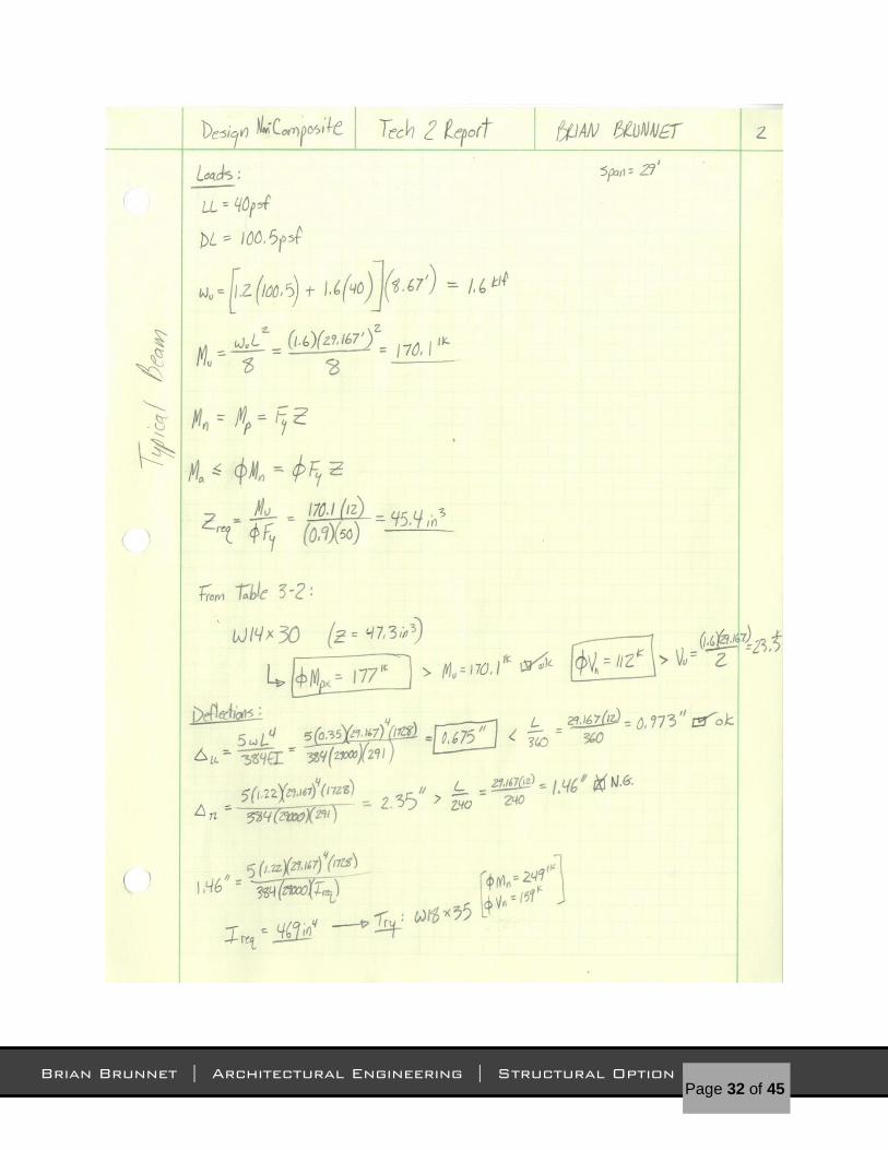
Upon evaluation of the non-composite system, it is found that a 2C22 non-composite
deck with 6” of total slab thickness was chosen to match fire protection requirements of
the original, and calculations conclude that the deck is adequate for the loads. This slab
was slightly thicker than the original; however it provided less capacity at the specific
clear span of 8’-8”. Furthermore, as for the intermediate beams within the bay, a
W18x35 beam would be sufficient in carrying the loads. When compared to the existing
structure, the W18x35 beams are deeper and heavier than the W16x31 beams and also
provided less strength in both shear and moment along with larger deflections. The
girder calculation produced a similar situation as was found with the beams. A W21x48
transfer girder would be effective at meeting the design criterion; however it is also
deeper and heavier than the existing W18x35 transfer girder.
Since this system doesn’t allow the concrete slab to carry any stresses, the steel must
carry the full effect from the applied loads. This would cause larger beam sizes when
compared to a composite system using the same bay size and framing plan.
Advantages
The advantage to using this system is that it has been used for many years in the past,
and the majority of building designers and structural engineers easily understand how to
design this system economically and efficiently. Many construction companies and
steel erectors are also familiar with constructing this system, which can save time and
money when erecting a building using this system.
Disadvantages

Page 15 of 45
Brian Brunnet | Architectural Engineering | Structural Option
The main disadvantage to using this system is the fact that the structural framework
receives greater stresses under loading since it carries the full set of loads. In
composite construction, the concrete slab contains the compressive stresses involved,
allowing the structural steel framework to be smaller in size at the same spans. Another
disadvantage to this system is that since the steel is under higher stresses, it leads to
considerably deeper and heavier steel shapes, with wide flanges ranging in depth from
2 to 3 feet. This leads to issues with ceiling heights and floor to floor heights, similar to
that mentioned with composite construction earlier in the report.
Figure 9: Typical non-composite steel system.
Page 16 of 45
Brian Brunnet | Architectural Engineering | Structural Option
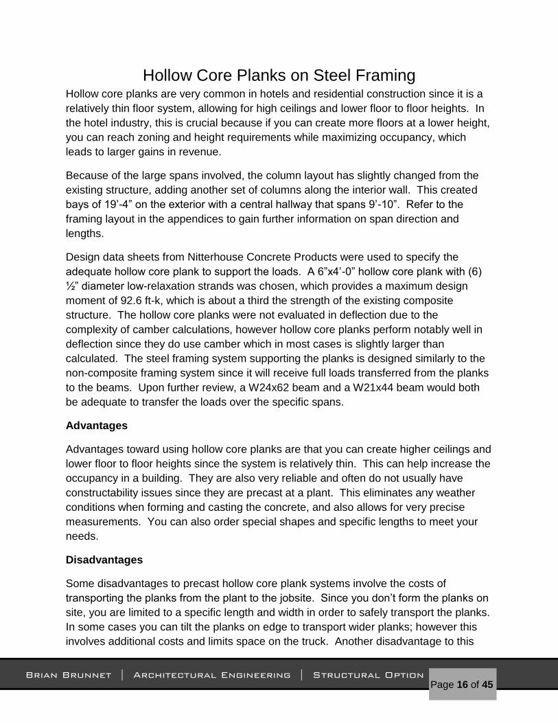
Hollow Core Planks on Steel Framing Hollow core planks are very common in hotels and residential construction since it is a
relatively thin floor system, allowing for high ceilings and lower floor to floor heights. In
the hotel industry, this is crucial because if you can create more floors at a lower height,
you can reach zoning and height requirements while maximizing occupancy, which
leads to larger gains in revenue.
Because of the large spans involved, the column layout has slightly changed from the
existing structure, adding another set of columns along the interior wall. This created
bays of 19’-4” on the exterior with a central hallway that spans 9’-10”. Refer to the
framing layout in the appendices to gain further information on span direction and
lengths.
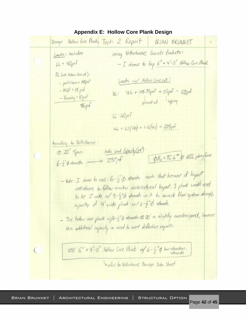
Design data sheets from Nitterhouse Concrete Products were used to specify the
adequate hollow core plank to support the loads. A 6”x4’-0” hollow core plank with (6)
½” diameter low-relaxation strands was chosen, which provides a maximum design
moment of 92.6 ft-k, which is about a third the strength of the existing composite
structure. The hollow core planks were not evaluated in deflection due to the
complexity of camber calculations, however hollow core planks perform notably well in
deflection since they do use camber which in most cases is slightly larger than
calculated. The steel framing system supporting the planks is designed similarly to the
non-composite framing system since it will receive full loads transferred from the planks
to the beams. Upon further review, a W24x62 beam and a W21x44 beam would both
be adequate to transfer the loads over the specific spans.
Advantages
Advantages toward using hollow core planks are that you can create higher ceilings and
lower floor to floor heights since the system is relatively thin. This can help increase the
occupancy in a building. They are also very reliable and often do not usually have
constructability issues since they are precast at a plant. This eliminates any weather
conditions when forming and casting the concrete, and also allows for very precise
measurements. You can also order special shapes and specific lengths to meet your
needs.
Disadvantages
Some disadvantages to precast hollow core plank systems involve the costs of
transporting the planks from the plant to the jobsite. Since you don’t form the planks on
site, you are limited to a specific length and width in order to safely transport the planks.
In some cases you can tilt the planks on edge to transport wider planks; however this
involves additional costs and limits space on the truck. Another disadvantage to this

Page 17 of 45
Brian Brunnet | Architectural Engineering | Structural Option
specific system is that it limits floor plan layouts due to the steel framework. Although
the planks are thin, the beams will be deep to carry the loads, so usually they will be
hidden within walls and partitions. This restricts room layouts and sizes that can cause
aesthetic issues.
Figure 10: Typical precast hollow core plank w/ embedded reinforcement.

Page 18 of 45
Brian Brunnet | Architectural Engineering | Structural Option
One-Way Post-Tensioned Flat Plate System When designing this system, the similar column layout from the existing plans was used
to help keep floor plan opportunities open, so I had the tendons span over the 19’-4”
and 29’-2” bays. Upon review, it was found that using an 8” slab with 3000psi concrete,
the design calls for a tendon consisting of (12) 0.196” diameter strands to carry the
loads. The eccentricity at mid-span on the larger span would be at 2”, which was at the
maximum due to cover requirements. The eccentricity on the shorter span was at
0.318”, which allows the tendon to create a general balanced upward force over the
entire slab to resist dead loads. Spacing between each tendon was calculated to be 18”
on center. The max moment found was 13.1 ft-k / ft width, or 113.6 ft-k when
comparing it to the tributary width of the existing structure, which is significantly weaker
than the existing composite system. Calculated shear produced similar results.
Design criteria such as deflection or vibration were not checked in this report due to the
inherent complexity of PT systems. However, post-tensioned systems perform notably
well against deflection issues, since the balanced moment supplied by the stressed
tendons creates a camber effect on the slab, reducing deflections significantly. This is a
main reason why it can be used for larger spans.
Advantages
Post-tensioned systems can offer a solution toward long span conditions. Since PT
systems apply an upward force from the tendon, they create a camber effect on the slab
which when loads are applied to the slab, the slab balances these gravity forces. This
allows the concrete to span large bays without negative effects from large deflections.
PT flat plate systems also offer adequate fireproofing due to the thick 8” of concrete
between each level.
Disadvantages
The main disadvantage of post tensioned systems comes from constructability issues.
Placing the tendons is a very time consuming job, since each tendon must have the
correct amount of drape in order to function as intended. Safety is also an issue when
jacking the tendons. Forces in the hundreds of thousands are being applied to these
tendons, creating a very destructive outcome if one was to rupture. If any types of
repairs are necessary in an older building using post tensioned slabs, cutting through a
post tensioned slab is highly dangerous since you would be releasing some of these
internal forces.

Page 19 of 45
Brian Brunnet | Architectural Engineering | Structural Option
Impact on Lateral System Post Tensioned and Hollow Core Plank Systems
Floor systems mainly utilizing concrete such as the post tensioned and hollow core
systems provide a slightly more massive system, depending on the thickness of the
slab. This increase in mass would create larger story shear forces in an earthquake.
However, a building made of a concrete structural and lateral system tends to be quite
rigid, meaning that the structure will have a low period of vibration. Although the site is
located in Buffalo, NY, earthquake forces are prevalent and must be compensated for in
design. A low period of vibration in this area would be suitable since many of the
earthquakes seen here are infrequent and usually quite low in magnitude. Both post
tensioned systems and hollow core plank systems usually work well with a concrete
frame, which most often incorporates shear walls for their lateral system. If one of these
systems were used for this building, it would be wise to reconsider different lateral
systems that may be more compatible with concrete construction.
Composite and Non-Composite Systems
Composite and non-composite floor systems tend to mainly utilize steel for its structural
system. This use of steel makes it easy to tie the floor system into either a brace frame
or moment frame lateral system. Steel generally behaves well in a building and
generally flexes with each passing wave. Because of the general height and shape of
the building, a mainly steel structure should perform well in this location.
Foundations
The foundation is mainly sitting on limestone bedrock with some structural fill supporting
it as well. If you are using lightweight concrete in either post tensioned or hollow core
plank systems, you shouldn’t have much of a settlement issue or any types of punching
shear problems, similar with steel structural systems.

Page 20 of 45
Brian Brunnet | Architectural Engineering | Structural Option
Systems Comparison Each system is compared based on the following criteria: slab weight, slab depth,
system depth, vibration control, fire rating, additional fireproofing, constructability,
formwork, floor to floor height, lead time, system cost, and feasibility. Table 3 below
illustrates the system comparison by highlighting best choice in green and worst choice
in red.
Composite Non-
Composite Hollow Core Plank Post Tensioned
Slab Weight 42psf 48psf 49psf 80psf
Slab Depth 5.25" 6" 6" 8"
System Depth 17.7" 20.6" 23.7" 8"
Vibration Control Yes Yes No Yes
Fire Rating 2 hr. 2 hr. 2 hr. 2 hr.
Additional Fireproofing Yes Yes No No
Constructibility Easy Easy Easy Hard
Formwork No No No Yes
Floor to Floor Height Increased Increased Decreased Decreased
Lead Time Short Short Long Short
System Cost $24.20 $28.60 $34.20 $22.60
Feasibility Existing Outdated Possible Most Possible
Table 3: Comparison Data

Page 21 of 45
Brian Brunnet | Architectural Engineering | Structural Option
Here are some strength comparisons between each floor system via Table 4 below.
moment capacity
(ft-k) shear capacity (k) deflection live (in.) deflection dead (in.)
composite: - - - -
beam 394 344 0.2 0.83
girder 483.3 376.2 0.225 0.933
Non-composite: - - - -
beam 249 159 0.385 1.34
girder 398 217 0.297 1.23
hollow core 92.6 - - -
beam b1 574 306 0.33 1.33
beam b2 358 217 0.252 1.01
post tensioned 13.1 /ft width 5.243 /ft width - -
Table 4: Comparison Data for Strength & Deflection

Page 22 of 45
Brian Brunnet | Architectural Engineering | Structural Option
Final Summary Technical Report 2 is meant to explore the differences in strength, serviceability, cost,
weight, and structural depth between the existing structural floor system and three other
types of floor systems. These different systems were reviewed in order to discover
which system would be fitting for future design considerations.
The existing composite beam and girder system seems to be the best solution. They
use a minimal amount of steel, it is easy to construct, it is relatively cheap and relatively
low weight. However the post tensioned floor system provided some surprising results
such as system depth that help qualify it as another close possibility. It almost matched
every quality when looking at aesthetic topics such as floor to floor height, yet its main
drawback is the difficulty it creates to construct during construction. Otherwise, the
benefits of the post tensioned floor system mainly outweighed the flaws, making it my
second best choice and a viable alternative.
The hollow core plank floor system seemed to be relatively strong, reduced system
depth and floor to floor height, and lightweight, the cost of the floor system was
considerably larger than every other system. This system would also have some
architectural design issues because of floor plan restrictions as well as possible ceiling
finishes. Vibration would be more prevalent in this system as well. The system was
therefore rejected, and will no longer be considered as an alternative floor system.
The non-composite floor system design is a relatively older system, however is very well
understood in the industry. It is easy to design, construct, and attain materials to build a
steel non-composite floor system. It is very similar to the composite system, however
the steel framing below the concrete decking mainly carries the entire set of stresses
due to the loads above. In composite construction, the slab helps the steel carry these
stresses which reduce the amount of structural steel needed to support the loads.
Since the existing system uses a composite floor system already, it is virtually and
economically unnecessary to use this floor system. Therefore this system was rejected
as well and will no longer be considered as an alternative.

Page 23 of 45
Brian Brunnet | Architectural Engineering | Structural Option
Appendices Appendix A: Framing Plan & Elevations
Figure 11: Column Grid Layout Plans (East End on bottom, West End on
top) Details courtesy of Cannon Design.

Page 24 of 45
Brian Brunnet | Architectural Engineering | Structural Option
Figure 12: Concentric
HSS Brace Frames and
Connection Details. Details
courtesy of Cannon Design.

Page 25 of 45
Brian Brunnet | Architectural Engineering | Structural Option
Figure 13: Typical Floor Plan of existing structure with bays used in calculations
highlighted. Drawings courtesy of Cannon Design.

Page 26 of 45
Brian Brunnet | Architectural Engineering | Structural Option
Appendix B: Composite Steel Analysis (existing structure)

Page 27 of 45
Brian Brunnet | Architectural Engineering | Structural Option

Page 28 of 45
Brian Brunnet | Architectural Engineering | Structural Option

Page 29 of 45
Brian Brunnet | Architectural Engineering | Structural Option

Page 30 of 45
Brian Brunnet | Architectural Engineering | Structural Option

Page 31 of 45
Brian Brunnet | Architectural Engineering | Structural Option
Appendix C: Non-Composite Steel Design
Page 32 of 45
Brian Brunnet | Architectural Engineering | Structural Option

Page 33 of 45
Brian Brunnet | Architectural Engineering | Structural Option

Page 34 of 45
Brian Brunnet | Architectural Engineering | Structural Option

Page 35 of 45
Brian Brunnet | Architectural Engineering | Structural Option

Page 36 of 45
Brian Brunnet | Architectural Engineering | Structural Option
Appendix D: Post-Tensioned Design

Page 37 of 45
Brian Brunnet | Architectural Engineering | Structural Option

Page 38 of 45
Brian Brunnet | Architectural Engineering | Structural Option

Page 39 of 45
Brian Brunnet | Architectural Engineering | Structural Option

Page 40 of 45
Brian Brunnet | Architectural Engineering | Structural Option

Page 41 of 45
Brian Brunnet | Architectural Engineering | Structural Option
Page 42 of 45
Brian Brunnet | Architectural Engineering | Structural Option
Appendix E: Hollow Core Plank Design

Page 43 of 45
Brian Brunnet | Architectural Engineering | Structural Option

Page 44 of 45
Brian Brunnet | Architectural Engineering | Structural Option

Page 45 of 45
Brian Brunnet | Architectural Engineering | Structural Option