ece532 design project group report disparity map
TRANSCRIPT

ECE532 Design Project Group Report
Disparity Map Generation Using Stereoscopic Camera on the Atlys Board
Team 3
Alim-Karim Jiwan Muhammad Tariq
Yu Ting Chen

2
Table of Contents 1 Project Overview ........................................................................................................................................ 4
1.1 Motivation ........................................................................................................................................... 4
1.2 Goal ..................................................................................................................................................... 4
1.3 System Diagram .................................................................................................................................. 5
1.4 Description of IP Cores ........................................................................................................................ 5
2 Outcome .................................................................................................................................................... 6
2.1 Design Modification ............................................................................................................................ 6
2.2 Disparity Map Output ......................................................................................................................... 6
2.3 Performance Comparison ................................................................................................................... 8
3 Project Schedule ........................................................................................................................................ 9
4 Detailed Description of IP ........................................................................................................................ 10
4.1 Disparity Map Frontend – load_bram version 1.00.a ....................................................................... 10
4.2 Disparity Map Backend – disparity_out version 1.00.a .................................................................... 11
4.3 Disparity Map Calculation Block – Disp_Map_Calc .......................................................................... 11
4.4 MicroBlaze version 8.40.a ................................................................................................................. 13
4.5 Clock_generator version 4.03.a ........................................................................................................ 13
4.6 VmodCam version 1.01.a .................................................................................................................. 13
4.7 Proc_sys_reset version 3.00.a .......................................................................................................... 13
4.8 Pll_module version 2.00.a ................................................................................................................. 13
4.9 Lmb_v10 version 2.00.b .................................................................................................................... 13
4.10 Lmb_bram_if_cntlr version 3.10.a .................................................................................................. 13
4.11 Bram_block version 1.00.a .............................................................................................................. 13
4.12 HDMI_out version 1.00.a ................................................................................................................ 13
4.13 Mdm version 2.10.a ........................................................................................................................ 13
4.14 Axi_intc version 1.02.a .................................................................................................................... 13
4.15 Axi_interconnect version 1.06.a ..................................................................................................... 13
4.16 Axi_uartlite version 1.02.a .............................................................................................................. 13
4.17 Axi_gpio version 1.01.b ................................................................................................................... 13
4.18 Axi_s6_ddrx version 1.06.a ............................................................................................................. 13
5 Description of Design Tree ....................................................................................................................... 13
6 Tips and Tricks .......................................................................................................................................... 14

3
7 Reference ................................................................................................................................................. 15

4
1 Project Overview
1.1 Motivation
Depth detection is a technique used in many applications such as hazard avoidance in vehicles,
movement tracking in games, and tracking analysis in robotics. Detection of depth can be
accomplished by producing a disparity map for a set of input images which can then be used to
compute distance.
Disparity maps provide depth information for a given stereoscopic image pair. The disparity value
stored at a coordinate in the map is proportional to the distance of the object at that pixel
coordinate. In order to track depth in real-time, the computational resource and data requirement is
very high due to two input video streams. Thus, ideally the computation should be implemented in
hardware over software.
1.2 Goal
The goal of this project is to implement a disparity map generator hardware system on the Atlys
Board with input from the VmodCam stereoscopic camera. A disparity map presents the distance
information in an image. The disparity map generation process is computationally intensive and will
not meet the real-time requirement, thus the disparity map calculation was implemented as a
hardware accelerator on the Spartan 6 FPGA.
Video inputs are received from the VmodCam and stored into the DDR memory. The disparity map
generator hardware reads the video frames into BRAMs for processing and stores the final disparity
map image in DDR memory which can be displayed as a 640x480 image through the HDMI output.

5
1.3 System Diagram
Figure 1: Block Diagram of the Final System
1.4 Description of IP Cores
Table 1: Description of the IP cores within the system refer to Section 3 for a detailed description
IP Core Functionality Origin
disparity_map_frontend (i.e. load_bram)
Disparity map frontend fills the reference and search image frames into BRAM and the disparity map calculation is done in the Disp_Map_Calc module
Custom designed IP
disparity_map_backend (i.e. disparity_out)
Disparity map backend fills disparity map into DDR memory based on specified addressing to ignore borders where disparity is not calculated
Custom designed IP

6
MicroBlaze 32-bit RISC architecture FPGA-based soft processor
Xilinx IP
BRAM Block RAM Xilinx IP
dlmb_ctrl Data Local Memory Bus Controller Xilinx IP
ilmb_ctrl Instruction Local Memory Bus Controller
Xilinx IP
AXI 4 interconnect AXI Bus Xilinx IP
clock_generator Generates the various clocks needed in system
Xilinx IP
vmodcam_in Receives input from 2 video feeds of the VmodCam and stores the images to separate memory locations
Custom modified
hdmi_out Reads from DDR memory and outputs to monitor in various formats
Provided by previous group
Table 2: Description of the hardware components used in the design external to the Spartan 6 FPGA
Component Functionality
VmodCam Provides video input in various data formats from two 2-megapixel digital image sensors at maximum 1600x1200 resolution at 15 FPS
DDR2 SDRAM 128MB Double data rate, 16-bit wide SDRAM on board memory
DVI Display Controller On chip controller for video output
2 Outcome
2.1 Design Modification
Table 3: Provides a comparison of the proposed implementation and actual implementation
Proposed Hardware Feature Status Comments
Input image filter None A proposed optional feature which was not implemented
Adaptive window sizing None Unimplemented feature due to time constraints
Sum of Absolute Difference Computation
Complete
Disparity Map Generation Complete
Output Filter None A proposed optional feature which was not implemented
2.2 Disparity Map Output
Functional verification of the output disparity image was performed through visual inspection in
several stages. The original MATLAB model produced disparity map was viewed in comparison

7
to reference tests obtained from a research paper [1]. Figure 2 shows the MATLAB results for a
common stereoscopic image pair.
Figure 2: MATLAB generated disparity map for Tsukuba image pair
The disparity map image generated by the hardware system and the original input images are
shown in Figure 3.
In order to compute a reliable disparity map, the camera inputs are expected to be closely
matched with the only difference being a shift in the images upon which the disparity can be
computed. However the disparity map output contains errors due to the imperfection in the
camera images such as differences in brightness between the frames.

8
Figure 3: Reference input image (top left), Search input image (top right), Final disparity map image (bottom)
A future step to be taken for a higher fidelity disparity map output is to perform filtering on the
final output image.
2.3 Performance Comparison
Table 4 shows the runtime of disparity map calculations in MATLAB, disparity map C program,
and the hardware system.
Table 4: Performance Comparison across platforms
System Frame Size Time
MATLAB 100x200 ~5 mins ( >1hr 640x480)
MicroBlaze 640x480 ~20 mins
Hardware System 640x480 2 - 8.5 seconds
The aim was to calculate disparity map on video input streams in real-time, however this could
not be achieved. Depending on the window sizing the hardware system can compute a full
disparity map in 2 to 8.5 seconds.
9
A simple modification to help meet the real-time aspect of the hardware system would be to
reduce the resolution of the video input. This would not be a permanent solution, however it
aids in satisfying the real-time requirement. Another performance improvement which can be
implemented is to increase parallelism of processing. Currently, the hardware design processes
one pixel at a time. In order to improve processing time, the frame may be separated into
multiple segments for multiple disparity map calculations to occur concurrently. This includes
instantiation of multiple BRAMs so a limitation is the size of available BRAMs on the FPGA.
Another way to speed up the disparity map computation is by using adaptive window sizing to
determine the size of the windows needed for the sum of absolute differences pixel matching
stage. An area of more variation, meaning a more textured region of the image, will require a
smaller window size due to its distinct pattern. As such, a smaller window can be used, leading
to less addition operations needed for a sum of absolute difference calculation.
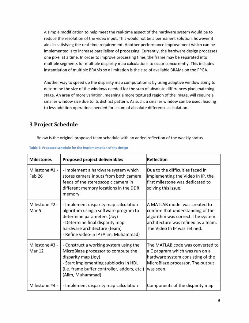
3 Project Schedule
Below is the original proposed team schedule with an added reflection of the weekly status.
Table 5: Proposed schedule for the implementation of the design
Milestones Proposed project deliverables Reflection
Milestone #1 - Feb 26
- Implement a hardware system which stores camera inputs from both camera feeds of the stereoscopic camera in different memory locations in the DDR memory
Due to the difficulties faced in implementing the Video In IP, the first milestone was dedicated to solving this issue.
Milestone #2 - Mar 5
- Implement disparity map calculation algorithm using a software program to determine parameters (Joy) - Determine final disparity map hardware architecture (team) - Refine video-in IP (Alim, Muhammad)
A MATLAB model was created to confirm that understanding of the algorithm was correct. The system architecture was refined as a team. The Video In IP was refined.
Milestone #3 - Mar 12
- Construct a working system using the MicroBlaze processor to compute the disparity map (Joy) - Start implementing subblocks in HDL (i.e. frame buffer controller, adders, etc.) (Alim, Muhammad)
The MATLAB code was converted to a C program which was run on a hardware system consisting of the MicroBlaze processor. The output was seen.
Milestone #4 - - Implement disparity map calculation Components of the disparity map

10
Mar 19 logic in HDL - Verification of individual subblocks in ModelSim (Alim, Muhammad)
hardware were implemented. Simulation and debugging of disparity_map_frontend. More debugging was needed for the C program so the disparity_map_backend design was delayed.
Milestone #5 - Mar 26
- Verify design in ModelSim - Debugging phase
Individual blocks simulated and ready for integration.
Milestone #6 - Apr 2
- Final integration of system - Verification of final integrated system
Full hardware system created and synthesized. Debugging phase for the full hardware system on FPGA concurrently with full system simulation. Ideally the system would be functional and outputs to display.
4 Detailed Description of IP
4.1 Disparity Map Frontend – load_bram version 1.00.a
This block interfaced with the AXI bus to grab the pixel data from DDR (which is loaded by the
VmodCAM). An FSM was created to handle AXI burst reads into a FIFO. The pixels coming from the
AXI read were RGB565 and there were 2 pixels per word. The load_bram block separated these
pixels from the FIFO and converted them individually into their greyscale value using a pixel
converter block. This greyscale pixel was then loaded into a BRAM. The load_bram block had two
BRAMS and two pixel converters for the reference and search image from the VmodCAM. The
BRAM’s contained 8 lines of the horizontal resolution, which allowed the disparity calculator to
calculate a maximum window size of 7. The extra line in the BRAM allowed the disparity calculator
to continue calculating disparities while the load_bram block could replace a finished row.
Specifically, a finished_row acknowledgement would be sent from the disparity calculator to the
load_bram block, whereby the oldest entry in the BRAM would be replaced by a new row of pixels.
A “go” signal was used to signal the disparity calculator when a BRAM was filled and ready to be
used. The load_bram tracked the number of finished_row acks from the disparity calculator to
determine the end of a frame and would de-assert the “go” signal during this time.
To test this block, I constructed a testbench with an AXI read FSM. It waited for the appropriate
axi_valid signals to go high and sent data into the block. It counted the number of data it was
sending and would de-assert the valid signals and send the rlast signal when it reached the
burst_length for the transaction. The data that was being sent in was just an incrementing bus

11
vector (rdata <= rdata + 1). Since the actual greyscale conversion was simple, the main testing
procedure focused on ensuring the data path was not disrupted and that the BRAM addressing was
correct.
4.2 Disparity Map Backend – disparity_out version 1.00.a
The disparity map backend handles the addressing logic for the disparity output. Due to the fact that
the disparity calculation cannot be performed on the borders of the images, there will be no output
grayscale pixel for certain columns of the image which needed to be accounted for when writing to
memory.
This block interfaces to the AXI bus as a burst master and performs master burst writes to the DDR2
SDRAM to store the disparity grayscale pixel to memory. The backend receives the disparity output
as 32-bit words containing two RGB565 pixel values in grayscale into a FIFO outputted from the
Disp_Map_Calc module within the disparity map frontend. Once the FIFO receives enough data for a
burst write, it will send a master write request to the AXI through the IP interface which handles the
AXI protocol.
The addressing logic is parameterized and is able to handle different frame sizes, starting addresses,
etc. These parameters may be set through modifying the .mhs file in the XPS project, by default the
core will handle a 640x480 frame size.
The IP core was simulated in ModelSim to verify that the addressing was correct and that the AXI
protocol was functioning correctly.
4.3 Disparity Map Calculation Block – Disp_Map_Calc
This block computes the disparity map from two frames using the sum of absolute differences
algorithm. This module used two BRAMs which are filled with the first eight lines from each frame
by the front-end module. It is able to handle window sizes of 1x1, 3x3, 5x5 and 7x7. Therefore, the
maximum number of rows required to compute the largest window is 7. Since the BRAMs are filled
with 8 rows of the frame, the disparity calculation can continue on to the next row while the new
row is being filled. This is accomplished by sending a finshed_row acknowledgement to the front-
end. After the calculation of each pixel disparity, it is converted into a greyscale pixel and a pair of
these pixels is pushed into a FIFO which is in the back-end module. The process of calculating the
disparity of each pixel is pipelined and thus requires a few assumptions from the front-end and the
back-end.
One of the assumptions is that a new row is filled in each BRAM before the calculation of the current
set of rows finishes such that the entire process does not need to stall. For example, if all operations

12
on rows 1 to 7 are completed, a finished_row signal is sent to the front-end. The disparity
calculation can continue to operate on rows 2 to 8. During this time the front-end module is
required to fill row 9 into the location of row 1 in each BRAM. This assumption holds as the lowest
number of cycles required to complete the disparity calculation on a set of rows is ~40,000. The
front-end uses a burst protocol which means that the total number of cycles to fill a row in each
BRAM is 640 if the burst request is fulfilled immediately. Even after considering the overhead of the
burst request, this assumption can be made due to the large number of cycles required to complete
the disparity calculation on a set of rows.
The other assumption is between the back-end and the disparity calculator. The back-end module is
expected to write the pixels within the FIFO to the DDR faster than the disparity calculator. This
assumption can also be made as it requires ~2048 cycles to complete the disparity calculation of 32
pixels and the AXI burst protocol should take approximately 16+ cycles to write 32 pixels.
The functionality of the disparity map calculation block was confirmed by simulating BRAMs with
random data and performing the calculation on small window frames. Once the simulation of small
window frames was functioning as expected, the target frame size of 640x480 was simulated along
with various window sizes. Since the block was parameterized, simulating different scenarios was
accomplished with ease.

13
4.4 MicroBlaze version 8.40.a
4.5 Clock_generator version 4.03.a
4.6 VmodCam version 1.01.a
4.7 Proc_sys_reset version 3.00.a
4.8 Pll_module version 2.00.a
4.9 Lmb_v10 version 2.00.b
4.10 Lmb_bram_if_cntlr version 3.10.a
4.11 Bram_block version 1.00.a
4.12 HDMI_out version 1.00.a
4.13 Mdm version 2.10.a
4.14 Axi_intc version 1.02.a
4.15 Axi_interconnect version 1.06.a
4.16 Axi_uartlite version 1.02.a
4.17 Axi_gpio version 1.01.b
4.18 Axi_s6_ddrx version 1.06.a
5 Description of Design Tree The following discusses only the key files in our project:
./Disparity_Map_Generator contains the XPS project with the whole system loaded
./Disparity_Map_Generator/workspace contains the SDK files, with disp_map_gen.c as the C program
to run for this project
./Disparity_Map_Generator/workspace/Push_buttons/src/disp_map_gen.c This code allows
pushbuttons to control the output to the HDMI. Refer to the README file for operation of this program
and to get your disparity map generated.
./Disparity_Map_Generator/pcores/load_bram_v1_00_a contains the RTL files for the
disparity_map_frontend project. This takes data from the DDR into FIFO’s, processes the pixels into

14
greyscale, and stores them into BRAMs. From the BRAMs, it calculates a disparity value and sends it to
the disparity_out block
./Disparity_Map_Generator/pcores/disparity_out_v1_00_a contains the RTL files for the
disparity_map_backend project. This takes the data from the frontend and writes it to the DDR for HDMI
output.
./Video contains a video of the working project
./Documentation Contains group report, presentation slides, and README for running the XPS
system and SDK program.
6 Tips and Tricks 1. A very important lesson learned by the team was the value of simulation. It is very difficult to
debug with the hardware design implemented on the FPGA. Simulations allow users to have the
transparency needed for debugging the hardware. Another advantage of simulation is that the
turnaround time for each compilation is significantly shorter than bitstream generation. Learn to
simulate early, and try to simulate the entire system including the AXI interface, MicroBlaze etc.
which will be useful later on in the project.
2. Incrementally test components methodically. It is not wise to implement a full system and
expect it to work, doing so also makes isolating the error difficult.
3. During testing, try to vary only one parameter at a time. Varying more than one factor is
confusing and cannot effectively isolate the problem.
4. Try to parameterize the pcore such that it can be easily changed through parameters in the
.mpd files in XPS instead of HDL code modification.

15
7 Reference
[1] Christos Georgoulas, Leonidas Kotoulas, Georgios Ch. Sirakoulis, Ioannis Andreadis, Antonios
Gasteratos, Real-time disparity map computation module, Microprocessors and Microsystems,
Volume 32, Issue 3, May 2008, Pages 159-170, ISSN 0141-9331,
http://dx.doi.org/10.1016/j.micpro.2007.10.002.
(http://www.sciencedirect.com/science/article/pii/S014193310700124X)