ece 451 advanced microwave measurements transmission linesemlab.uiuc.edu/ece451/notes/tl.pdf · ece...
TRANSCRIPT
ECE 451 – Jose Schutt‐Aine 1
ECE 451Advanced Microwave Measurements
Transmission Lines
Jose E. Schutt-AineElectrical & Computer Engineering
University of [email protected]
ECE 451 – Jose Schutt‐Aine 2
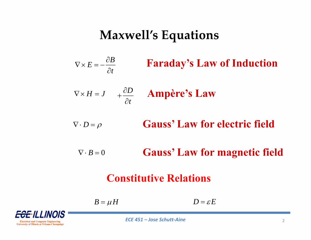
Faraday’s Law of Induction
Ampère’s Law
Gauss’ Law for electric field
Gauss’ Law for magnetic field
Constitutive Relations
BEt
H J Dt
D
0B
B H D E
Maxwell’s Equations
ECE 451 – Jose Schutt‐Aine 3
z
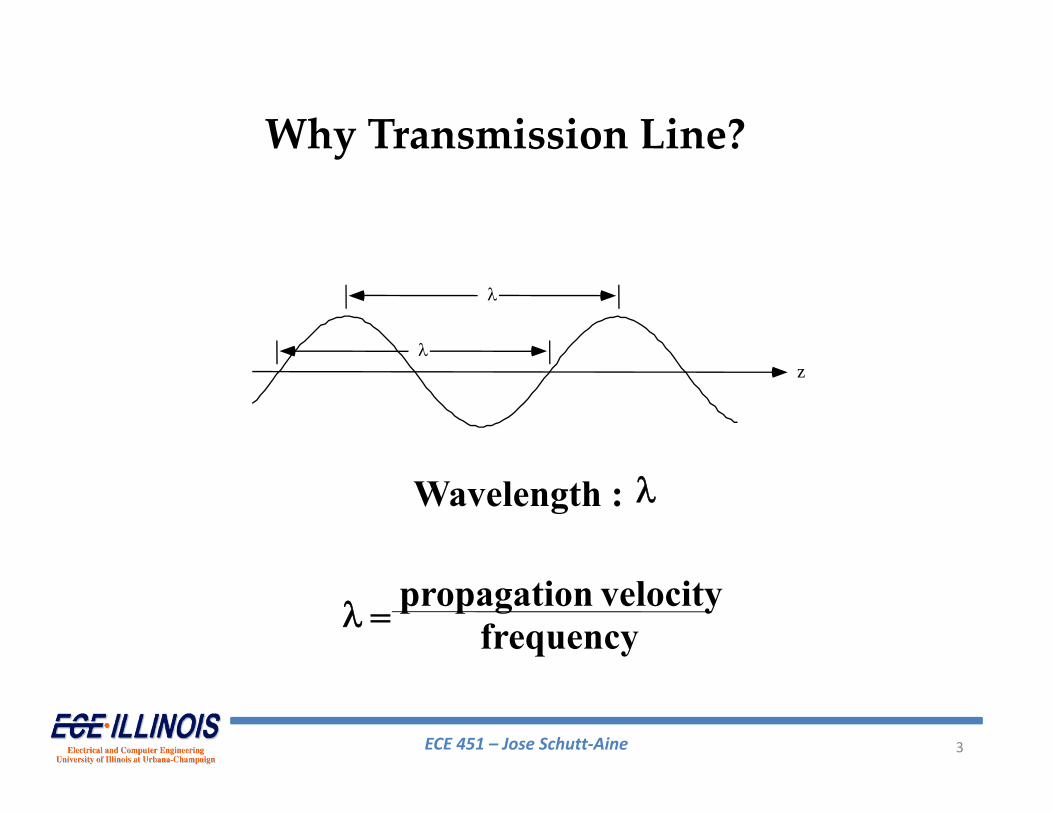
Wavelength :
= propagation velocity
frequency
Why Transmission Line?
ECE 451 – Jose Schutt‐Aine 4
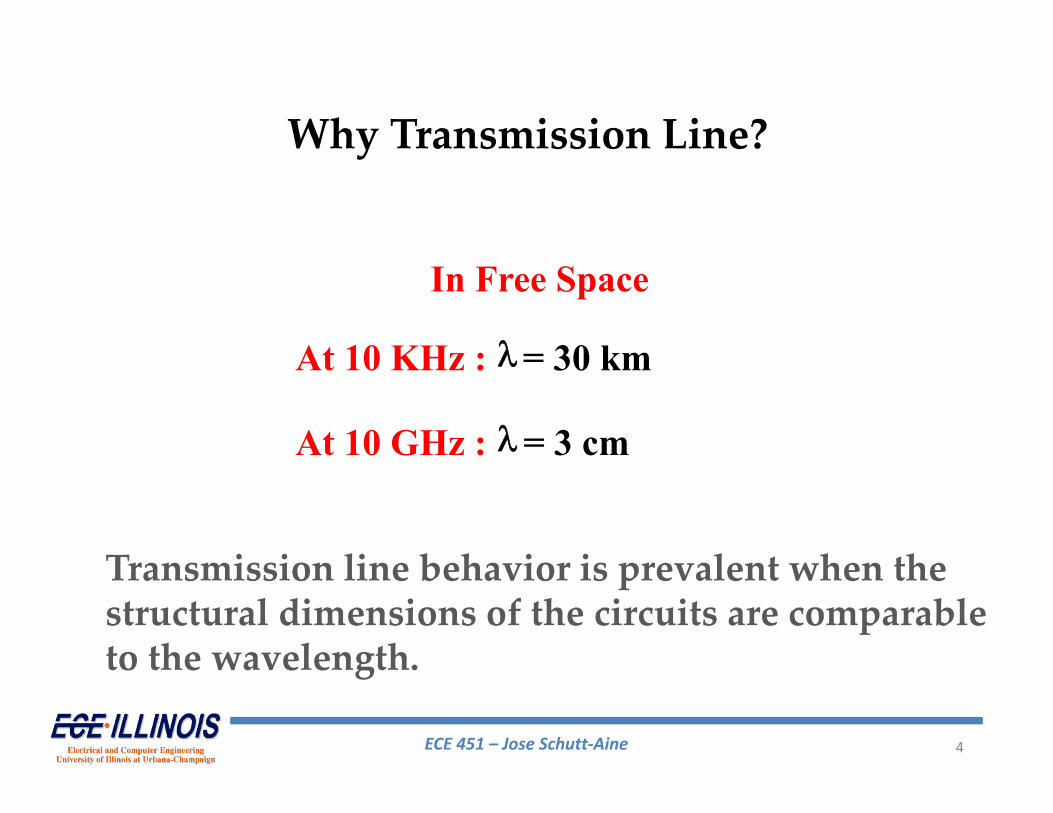
In Free Space
At 10 KHz : = 30 km
At 10 GHz : = 3 cm
Transmission line behavior is prevalent when the structural dimensions of the circuits are comparable to the wavelength.
Why Transmission Line?
ECE 451 – Jose Schutt‐Aine 5
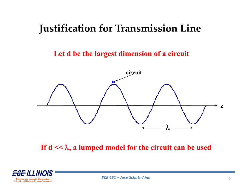
Let d be the largest dimension of a circuit
If d << , a lumped model for the circuit can be used
circuit
z
Justification for Transmission Line
ECE 451 – Jose Schutt‐Aine 6
circuit
z
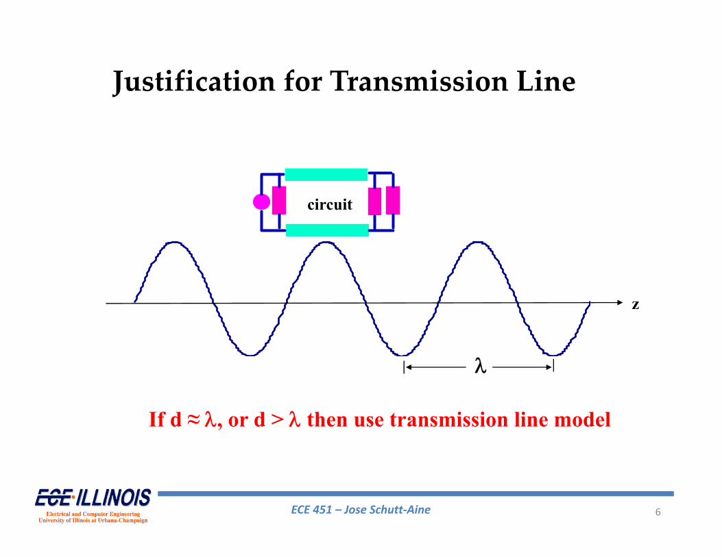
If d ≈ , or d > then use transmission line model
Justification for Transmission Line
ECE 451 – Jose Schutt‐Aine 7
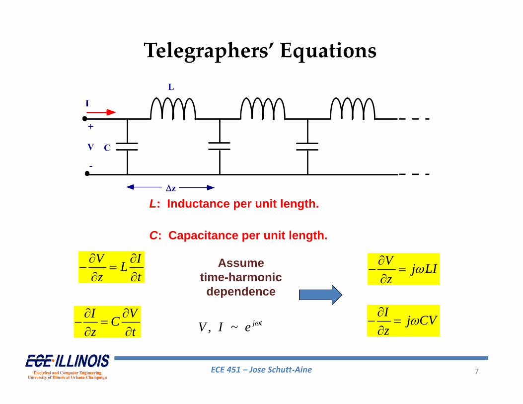
L: Inductance per unit length.
C: Capacitance per unit length.
L
z
C
I
V
+
-
V ILz t
I VCz t
V j LIz
I j CVz
Assumetime-harmonicdependence
, ~ j tV I e
Telegraphers’ Equations
ECE 451 – Jose Schutt‐Aine 8
L
z
C
I
V
+
-
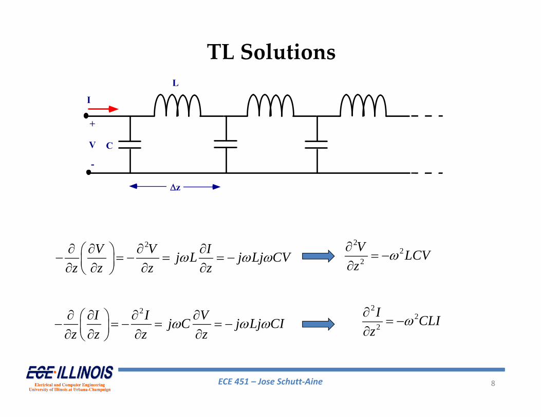
22
2
V LCVz
22
2
I CLIz
2V V Ij L j Lj CVz z z z
2 I I Vj C j Lj CI
z z z z
TL Solutions
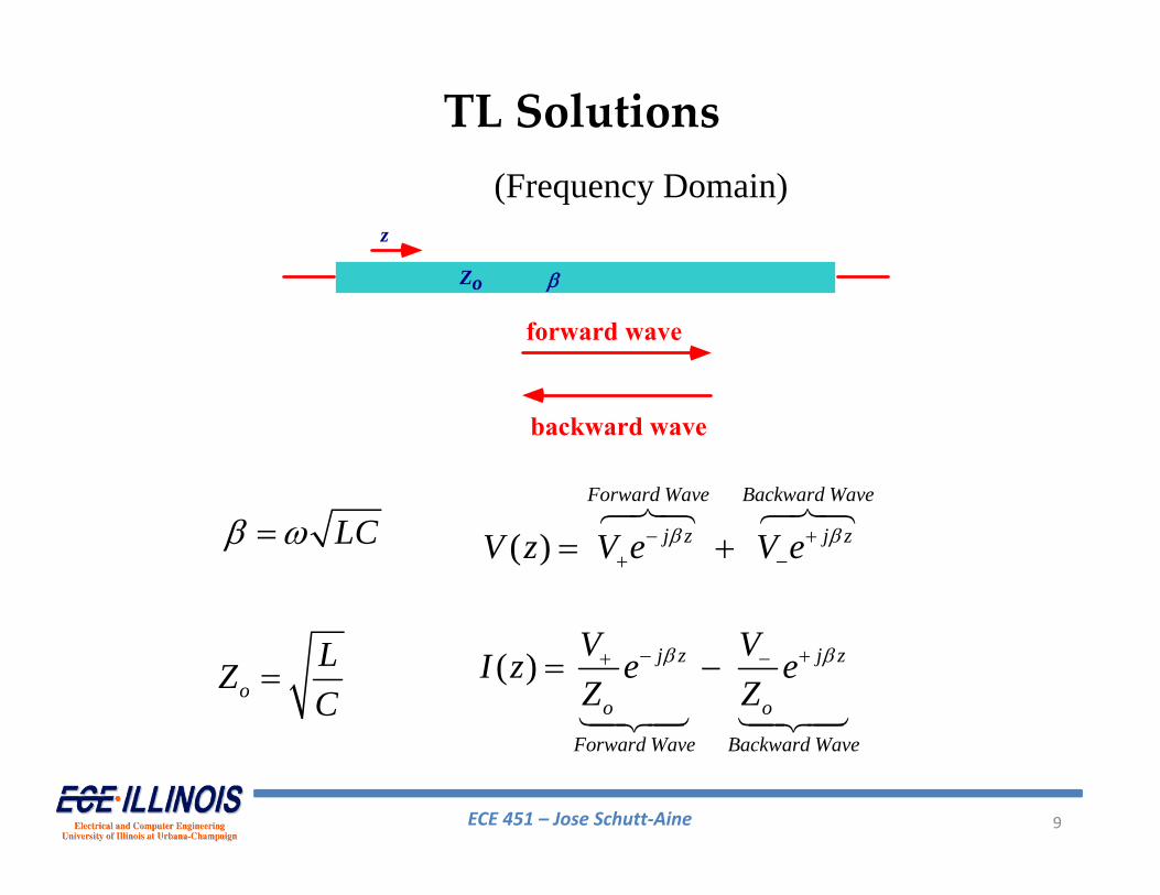
ECE 451 – Jose Schutt‐Aine 9
( )Forward Wave Backward Wave
j z j zV z V e V e
z
Zo
forward wave
backward wave
LC
oLZC
(Frequency Domain)
( ) j z j z
o o
Forward Wave Backward Wave
V VI z e eZ Z
TL Solutions
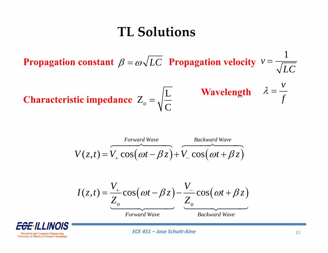
ECE 451 – Jose Schutt‐Aine 10
( , ) cos cosForward Wave Backward Wave
V z t V t z V t z
LC
oLZC
( , ) cos coso o
Forward Wave Backward Wave
V VI z t t z t zZ Z
1v
LC
vf
Propagation constant
Characteristic impedanceWavelength
Propagation velocity
TL Solutions
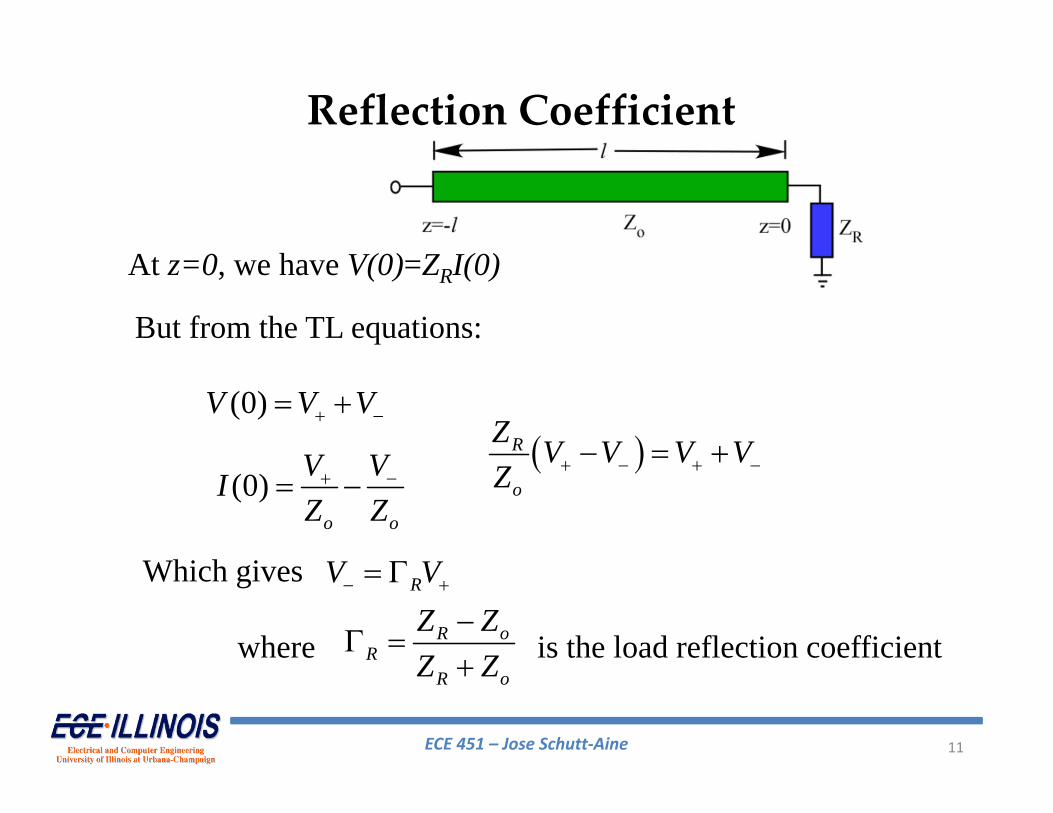
ECE 451 – Jose Schutt‐Aine 11
At z=0, we have V(0)=ZRI(0)
But from the TL equations:
(0)V V V
(0) o o
V VIZ Z
Which gives
R
o
Z V V V VZ
RV V
R oR
R o
Z ZZ Z
is the load reflection coefficientwhere
Reflection Coefficient
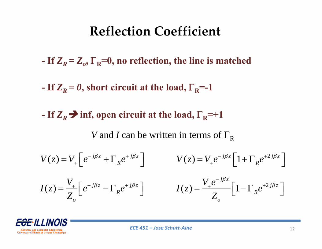
ECE 451 – Jose Schutt‐Aine 12
- If ZR = Zo, R=0, no reflection, the line is matched
- If ZR = 0, short circuit at the load, R=-1
- If ZR inf, open circuit at the load, R=+1
( ) j z j zRV z V e e
( ) j z j zR
o
VI z e eZ
2( ) 1j z j zRV z V e e
2( ) 1j z
j zR
o
V eI z eZ
Reflection Coefficient
V and I can be written in terms of R
ECE 451 – Jose Schutt‐Aine 13
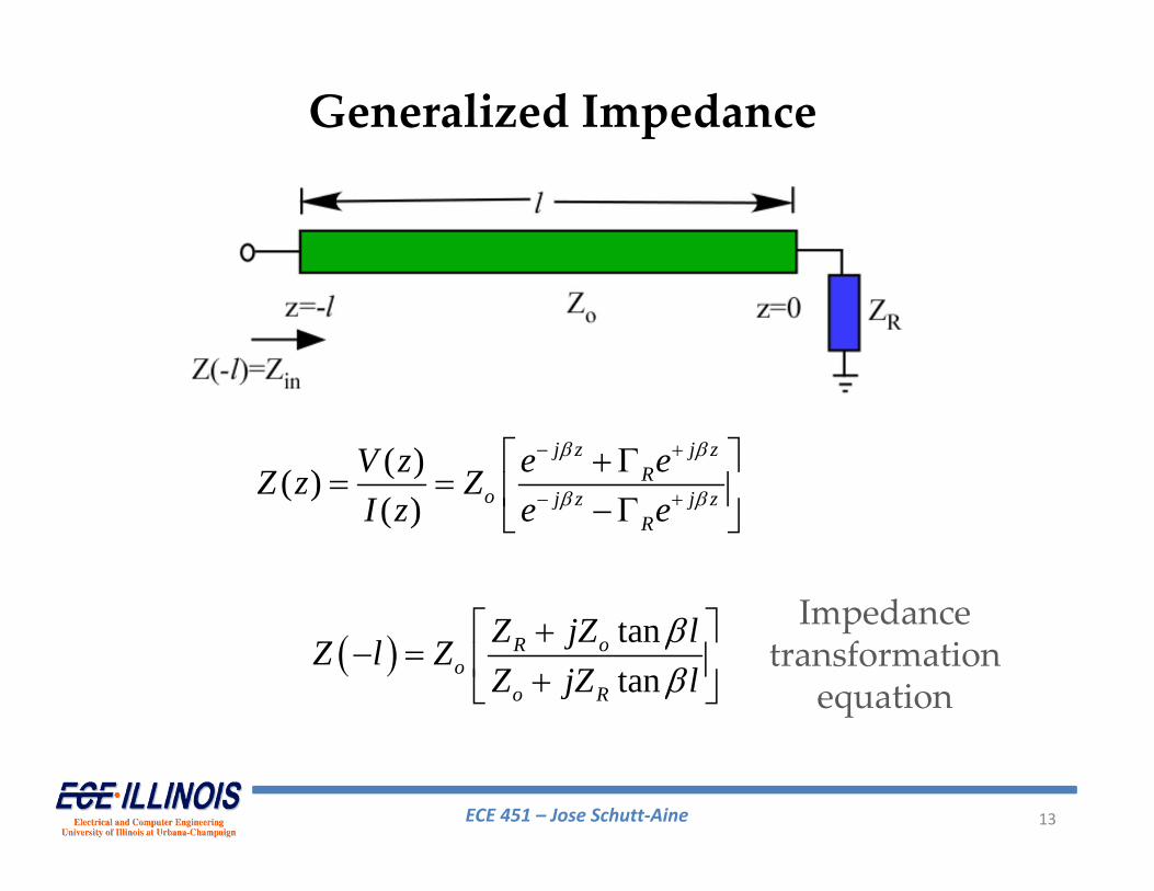
( )( )( )
j z j zR
o j z j zR
e eV zZ z ZI z e e
tantan
R oo
o R
Z jZ lZ l ZZ jZ l
Generalized Impedance
Impedance transformation
equation
ECE 451 – Jose Schutt‐Aine 14
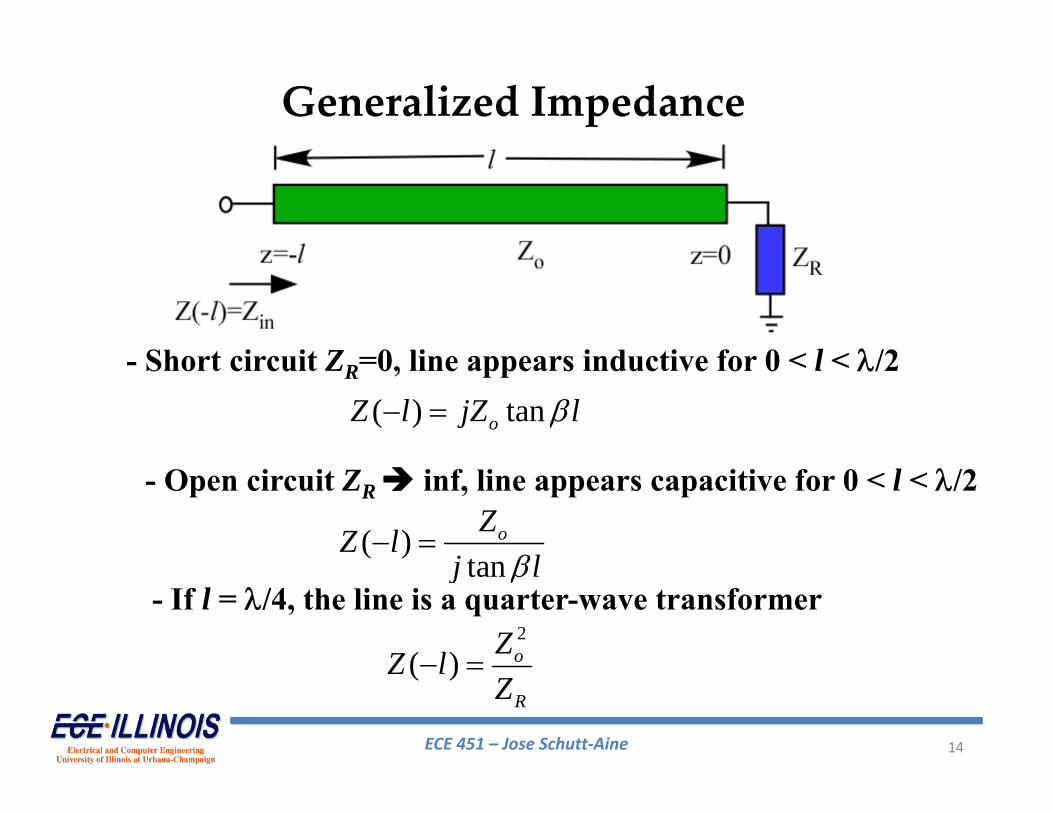
( ) tanoZ l jZ l
( )tan
oZZ lj l
- Short circuit ZR=0, line appears inductive for 0 < l < /2
- Open circuit ZR inf, line appears capacitive for 0 < l < /2
2
( ) o
R
ZZ lZ
- If l = /4, the line is a quarter-wave transformer
Generalized Impedance
ECE 451 – Jose Schutt‐Aine 15
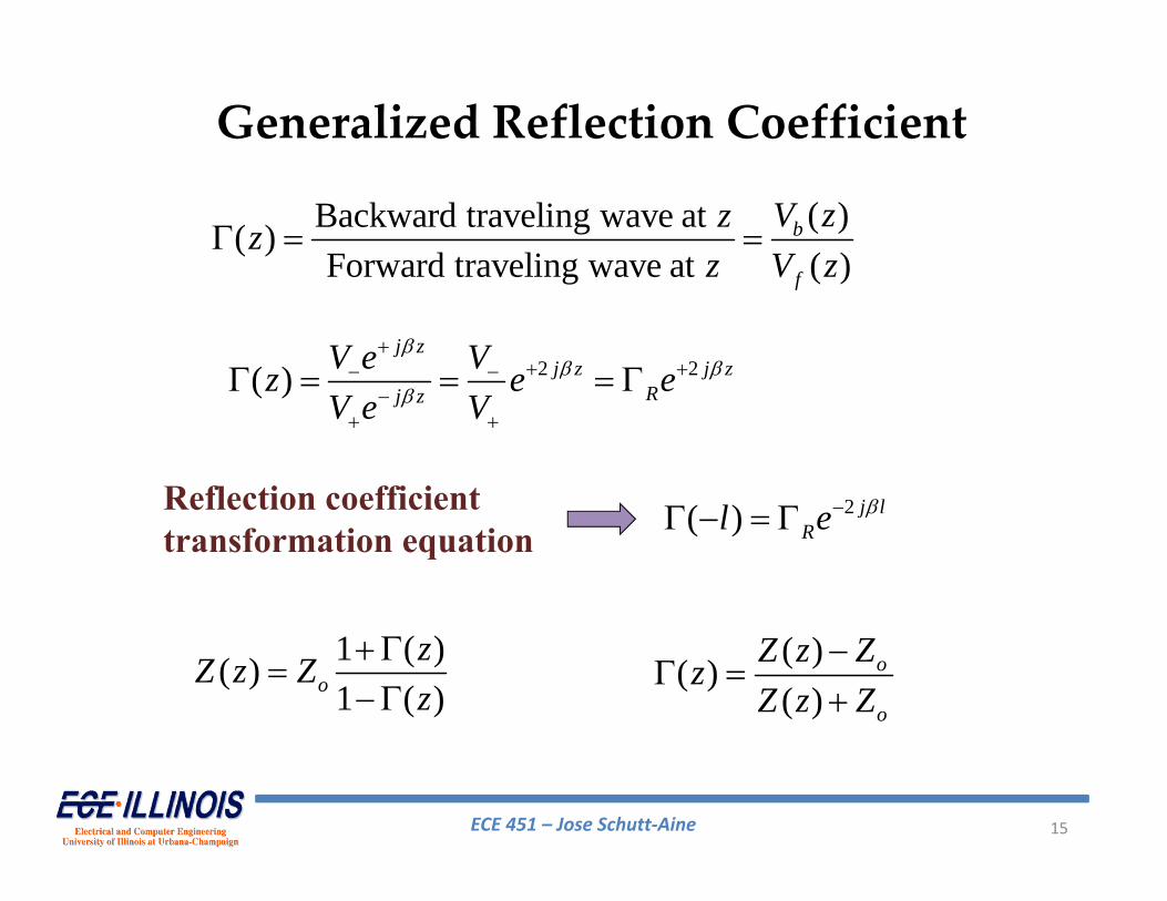
( )Backward traveling wave at( )Forward traveling wave at ( )
b
f
V zzzz V z
2 2( )
j z
j z j zRj z
V e Vz e eV e V
2( ) j lRl e Reflection coefficient
transformation equation
1 ( )( )1 ( )o
zZ z Zz
( )( )( )
o
o
Z z ZzZ z Z
Generalized Reflection Coefficient
ECE 451 – Jose Schutt‐Aine 16
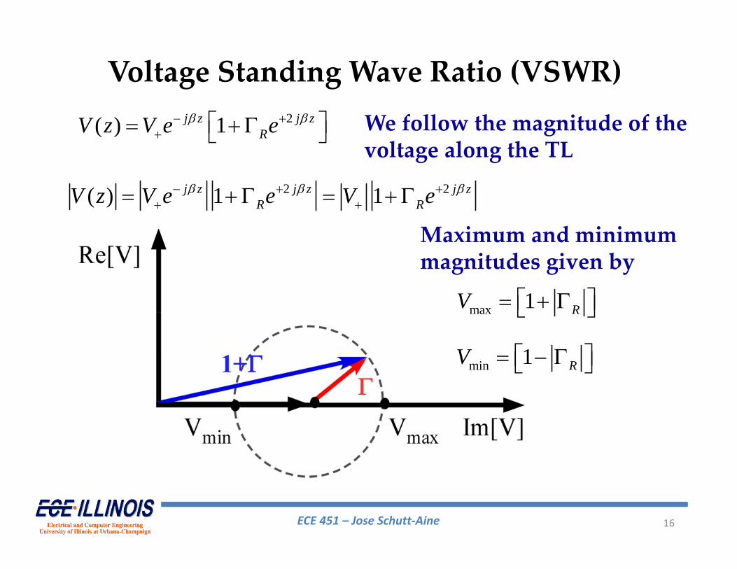
2( ) 1j z j zRV z V e e
2 2( ) 1 1 j z j z j z
R RV z V e e V e
max 1 RV
min 1 RV
Maximum and minimummagnitudes given by
Voltage Standing Wave Ratio (VSWR)We follow the magnitude of thevoltage along the TL
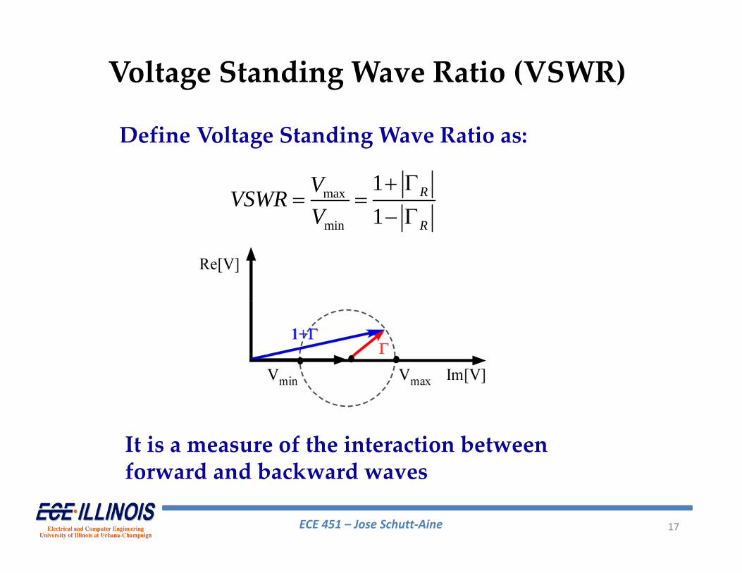
ECE 451 – Jose Schutt‐Aine 17
max
min
11
R
R
VVSWRV
Voltage Standing Wave Ratio (VSWR)
Define Voltage Standing Wave Ratio as:
It is a measure of the interaction between forward and backward waves
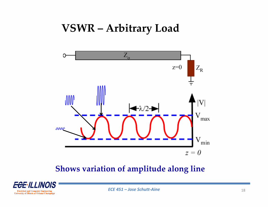
ECE 451 – Jose Schutt‐Aine 18
VSWR – Arbitrary Load
Shows variation of amplitude along line
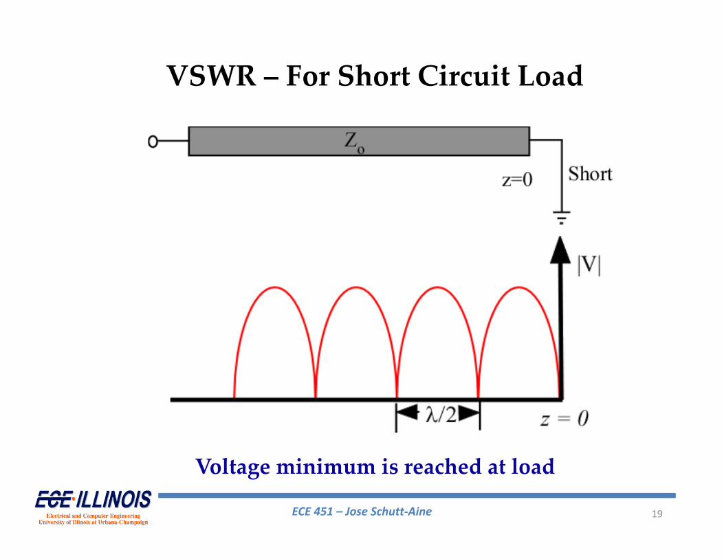
ECE 451 – Jose Schutt‐Aine 19
VSWR – For Short Circuit Load
Voltage minimum is reached at load
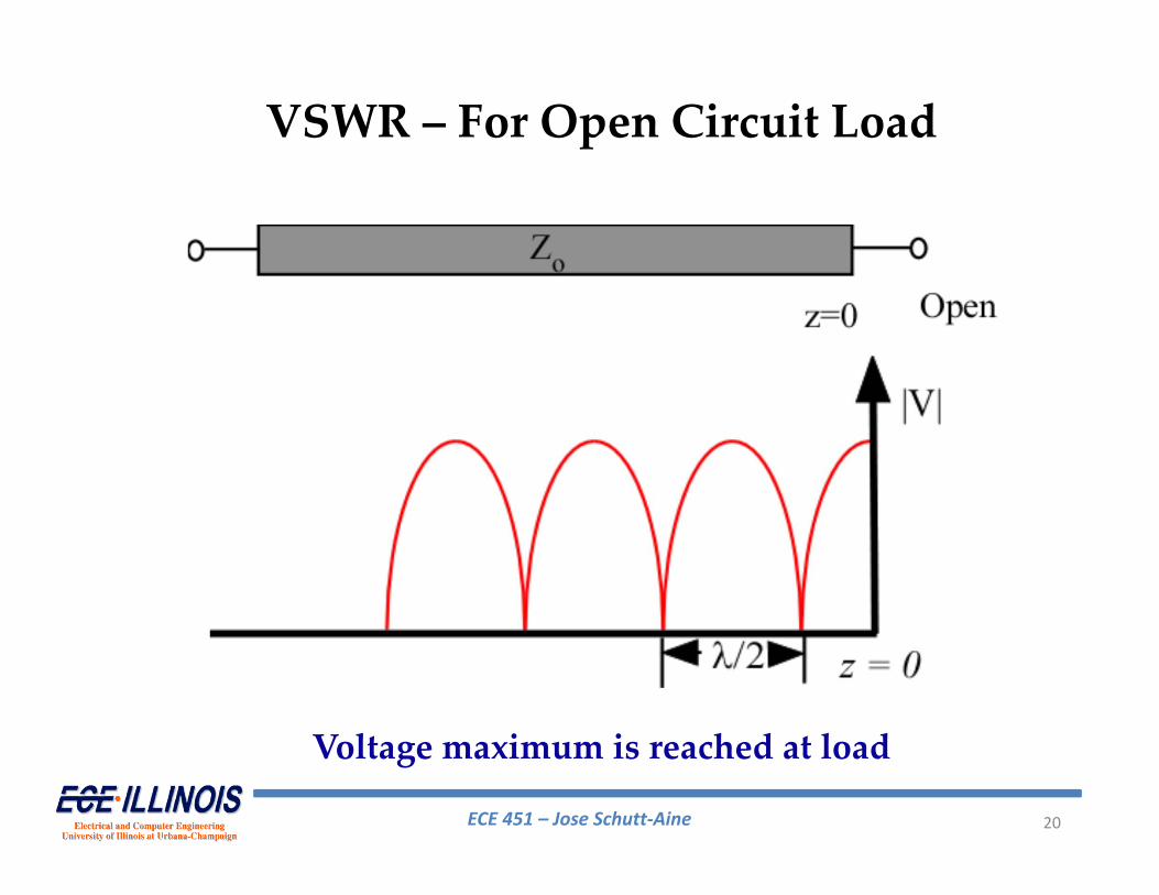
ECE 451 – Jose Schutt‐Aine 20
Voltage maximum is reached at load
VSWR – For Open Circuit Load
ECE 451 – Jose Schutt‐Aine 21
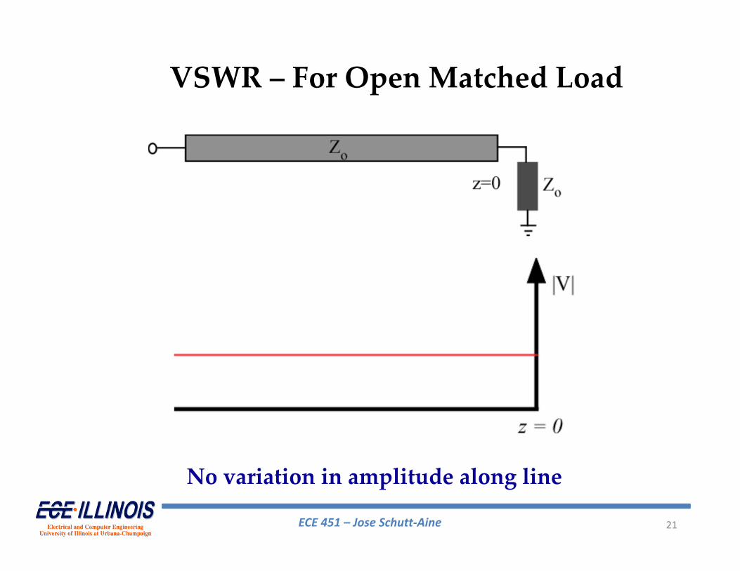
VSWR – For Open Matched Load
No variation in amplitude along line
ECE 451 – Jose Schutt‐Aine 22
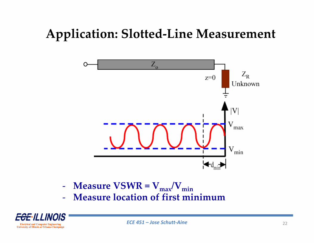
Application: Slotted‐Line Measurement
‐ Measure VSWR = Vmax/Vmin‐ Measure location of first minimum
ECE 451 – Jose Schutt‐Aine 23
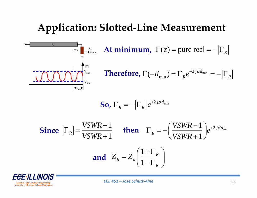
Application: Slotted‐Line Measurement
At minimum, ( ) pure real Rz
Therefore, min2min( ) j d
R Rd e
min2 j dR R e So,
11
RVSWRVSWR
Since min211
j dR
VSWR eVSWR
then
11
RR o
R
Z Zand
ECE 451 – Jose Schutt‐Aine 24
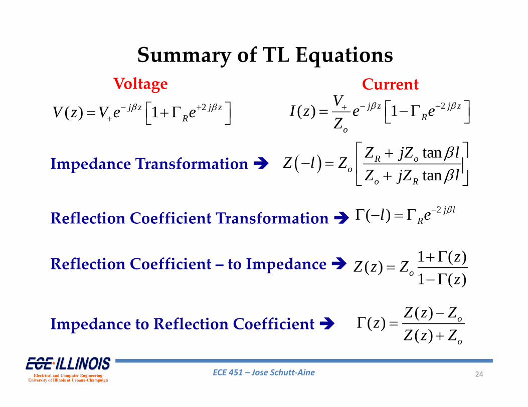
Summary of TL Equations
tantan
R oo
o R
Z jZ lZ l ZZ jZ l
2( ) j lRl e
1 ( )( )1 ( )o
zZ z Zz
( )( )( )
o
o
Z z ZzZ z Z
Impedance Transformation
Reflection Coefficient Transformation
Reflection Coefficient – to Impedance
Impedance to Reflection Coefficient
2( ) 1 j z j z
Ro
VI z e eZ
2( ) 1j z j zRV z V e e
Voltage Current
ECE 451 – Jose Schutt‐Aine 25
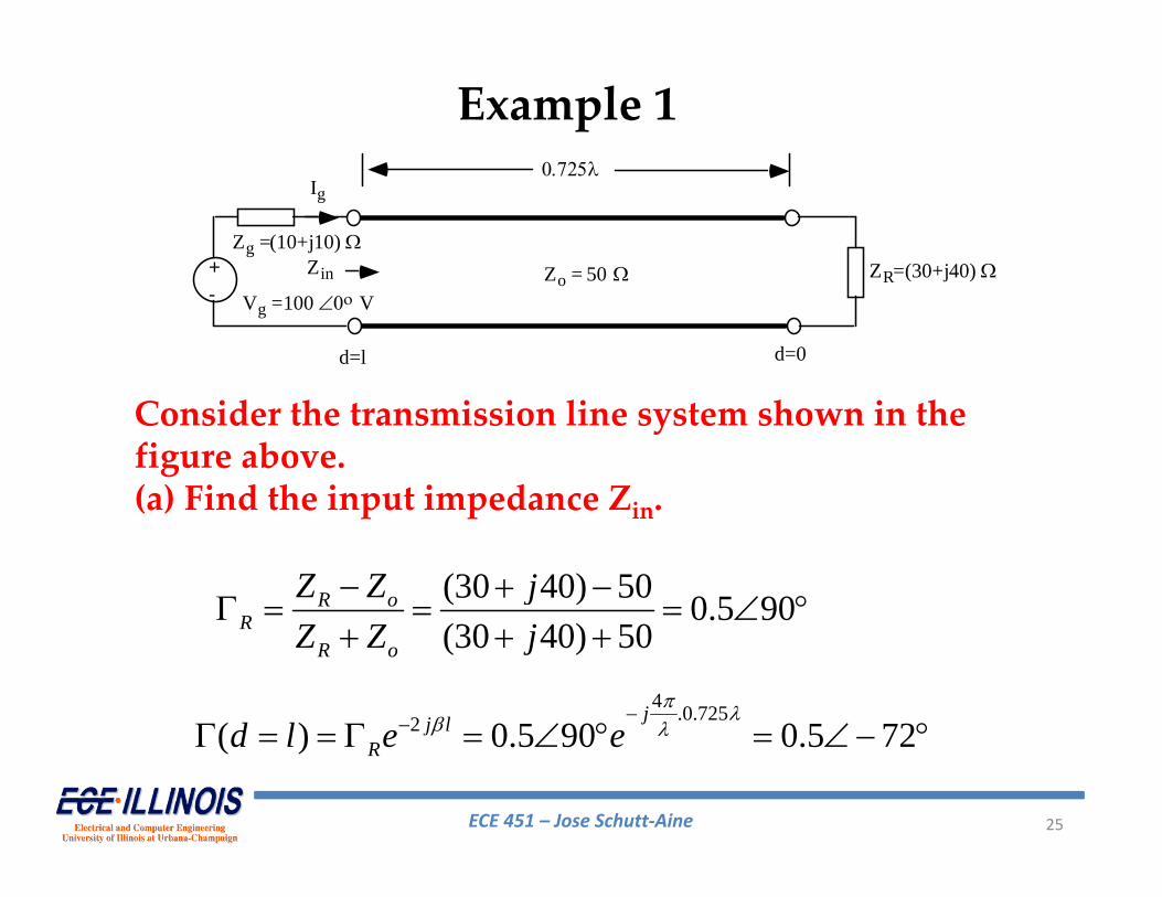
+- Vg =100 V
Zo = 50 Zg =(10+j10)
d=l d=0
ZR=(30+j40) Zin
Ig
Consider the transmission line system shown in the figure above.(a) Find the input impedance Zin.
(30 40) 50 0.5 90(30 40) 50
R oR
R o
Z Z jZ Z j
4 .0.7252( ) 0.5 90 0.5 72jj l
Rd l e e
Example 1
ECE 451 – Jose Schutt‐Aine 26
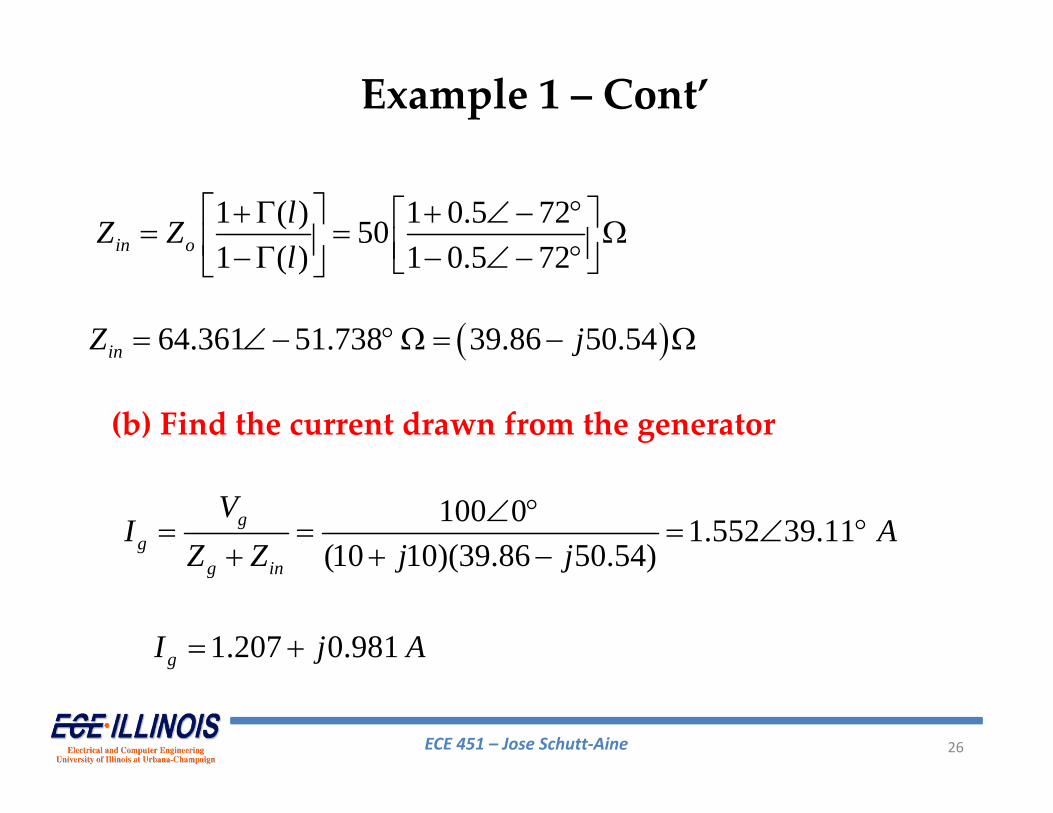
1 ( ) 1 0.5 72501 ( ) 1 0.5 72in o
lZ Zl
64.361 51.738 39.86 50.54inZ j
(b) Find the current drawn from the generator
100 0 1.552 39.11(10 10)(39.86 50.54)
gg
g in
VI A
Z Z j j
1.207 0.981gI j A
Example 1 – Cont’
ECE 451 – Jose Schutt‐Aine 27
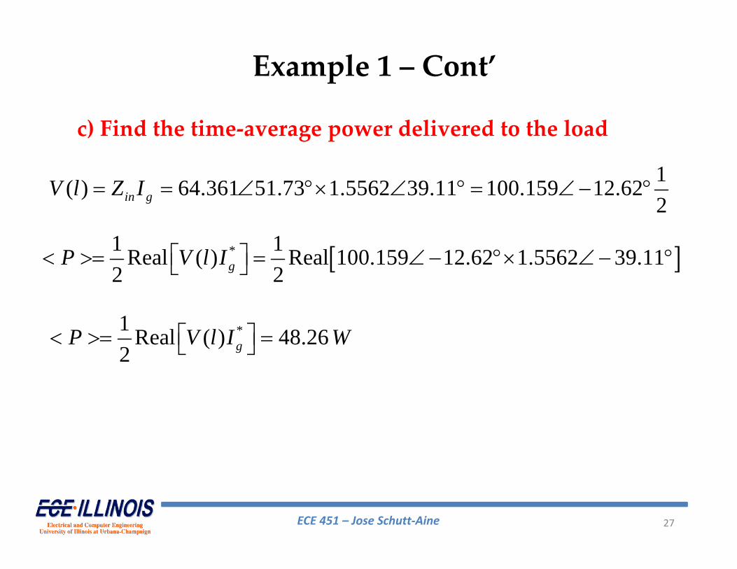
c) Find the time‐average power delivered to the load
1( ) 64.361 51.73 1.5562 39.11 100.159 12.622in gV l Z I
*1 1Real ( ) Real 100.159 12.62 1.5562 39.112 2gP V l I
*1 Real ( ) 48.262 gP V l I W
Example 1 – Cont’
ECE 451 – Jose Schutt‐Aine 28
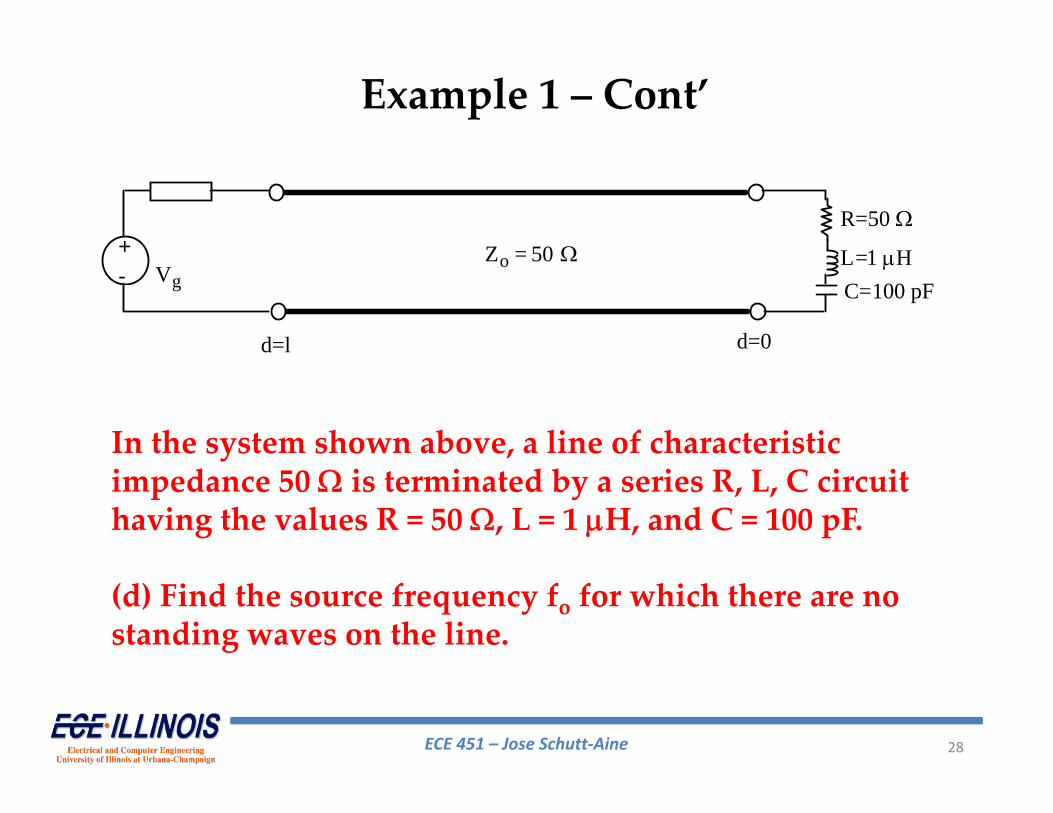
+- Vg
Zo = 50
d=l d=0
L=1 HC=100 pF
R=50
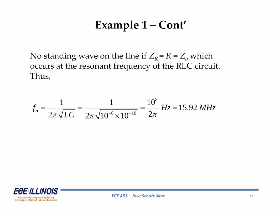
In the system shown above, a line of characteristic impedance 50 is terminated by a series R, L, C circuit having the values R = 50 , L = 1 H, and C = 100 pF.
(d) Find the source frequency fo for which there are no standing waves on the line.
Example 1 – Cont’
ECE 451 – Jose Schutt‐Aine 29
No standing wave on the line if ZR = R = Zo which occurs at the resonant frequency of the RLC circuit. Thus,
8
6 10
1 1 10 15.9222 2 10 10
of Hz MHzLC
Example 1 – Cont’