ebeam/fib 1540xb crossbeam standard operating procedure · 2017-09-29 · document: ebeam/fib...
TRANSCRIPT

DOCUMENT: Ebeam/FIB 1540XB Crossbeam Standard Operating Procedure Version: 1.0
Ebeam/FIB 1540XB Crossbeam Standard Operating Procedure
Version: 1.0 Oct 2014
UNIVERSITY OF TEXAS AT ARLINGTON
Nanotechnology Research Center

DOCUMENT: Ebeam/FIB 1540XB Crossbeam Standard Operating Procedure Version: 1.0
2
TABLE OF CONTENTS 1 INTRODUCTION ......................................................................... 3
1.1 Scope ...................................................................................................... 3
1.2 Description ............................................................................................... 3
1.3 Safety ...................................................................................................... 3
2 HARDWARE ............................................................................... 4
2.1 Process Gases: ..................................................................................... 4
2.2 Gemini FESEM 30kV Max ....................................................................... 4
2.3 Orsay Physics ExB FIB ............................................................................ 4
2.4 Raith Beam Blanker and Switch (Part No. 54-01-00-E01) ....................... 4
2.5 NPGS v9.0 Computer and Software ........................................................ 4
2.6 Edwards XDS10 Scroll Dry Pump ............................................................ 4
3 REQUIREMENTS ....................................................................... 4
3.1 Training .................................................................................................... 4
3.2 Restrictions .............................................................................................. 4
3.3 System checks ......................................................................................... 5
3.4 Vacuum checks ....................................................................................... 5
4 OPERATING PROCEDURE ....................................................... 5
4.1. System Login ........................................................................................... 5
4.2. Sample/ Specimen Holder Mounting ....................................................... 7
4.3. Loadlock Vent and Pump down ............................................................... 8
4.4. SEM Operation ...................................................................................... 13
4.5 Annotations and Measurements ............................................................ 21
4.6. Images and Pictures .............................................................................. 23
Appendix A
1.0 Ebeam Lithography .................................. Error! Bookmark not defined.
Appendix B
1.0 FIB Operation ………………………………………………………………..34

DOCUMENT: Ebeam/FIB 1540XB Crossbeam Standard Operating Procedure Version: 1.0
3
INTRODUCTION
Scope These procedures apply to the Ebeam/FIB 1540XB Crossbeam located in 101B. All maintenance should follow the procedures set forth in the manufacturer’s maintenance and operations manuals. This document is for reference only. Personnel should be trained by authorized staff before operating this equipment.
Description
The Ebeam/FIB is a high performance Schottky field emission SEM. It is capable of holding whole wafers making it a good tool for process control. The Ebeam/FIB has a resolution of 1-5 nm depending on the sample, current column conditions and skill of the operator. The 1540XB Crossbeam with the improved GEMINI® column is a true nanoscience FESEM. It provides ultra high resolution imaging over the complete voltage range with the ability to handle large awkwardly shaped specimens. A Raith Beam Blanker coupled with NPGS Software provides Ebeam Lithography capabilities. With an attached Orsay FIB it also provides Focus Ion Beam milling abilities while maintaining standard SEM abilities.
Safety
This machine is connected to HIGH VOLTAGE. Be very careful and aware of
electrical hazards. If you encounter any electrical malfunctions, contact NanoFAB staff immediately
This machine uses AC and DC power. DO NOT operate this machine with any component enclosures/panels open.
This machine has a 30 kV acceleration voltage Field Emission Scanning Electron Microscope Column (FE-SEM).
This instrument may generate radiation during operation! It is strictly prohibited to remove any cover panels, particularly those on the electro-optic column and the specimen chamber!
This machine has water flow interlocks to prevent over heating of turbo, electro-optics lenses and some electronics, if the water flow interlock error comes ON notify NanoFAB staff immediately.
This machine has NO EMO (Emergency Off) switch/button mounted on the equipment. The OFF switch should be pressed only in an emergency. An emergency would be fire, smoke, electrocution hazards, and an injury to anyone using this particular piece of equipment. If the OFF is pressed notify NanoFAB staff immediately.
This machine uses N2, gas which in high concentrations can be asphyxiates. The process gases are normally pumped out of the system. If the process pressure is not being maintained or system cannot reach base pressure notify NanoFAB staff immediately.

DOCUMENT: Ebeam/FIB 1540XB Crossbeam Standard Operating Procedure Version: 1.0
4
2 HARDWARE
2.1 Process Gases: N2, Triethoxymethysilane (Insulator), Tungsten Hexacarboynol (Tungsten) ,Xerendlflouride (Etchant) and Gallium Source
2.2 Gemini FESEM 30kV Max
2.3 Orsay Physics ExB FIB
2.4 Raith Beam Blanker and Switch (Part No. 54-01-00-E01)
2.5 NPGS v9.0 Computer and Software
2.6 Edwards XDS10 Scroll Dry Pump
2.7 System Computer
3 REQUIREMENTS
3.1 Training
3.1.1 You must be a qualified Ebeam/FIB 1540XB Crossbeam user. To become qualified you must first have submitted an Application to use NanoFAB SEM/EDS/FIB/Ebeam Writer Facilities and been approved. Once approved training will be scheduled and completed. Once completed you will be given a login consisting of your 1000 number as your ID and a password. Then you will be given access to the facilities in 101A or 101B or both as training dictates. There are no exams, completing the training is based on your ability to demonstrate you understand and can operate the equipment to the trainers’ approval.
3.2 Restrictions
3.2.1 No biological specimens/samples.
3.2.2 Always wear gloves when handling anything that goes in the system.
3.2.3 Only electrically conductive tape may be used.
3.2.4 The Ebeam is used at a WD= 6mm and FIB at a WD= 5mm
3.2.5 The FIB is NOT to be used to write patterns, only used for milling purposes.
DOCUMENT: Ebeam/FIB 1540XB Crossbeam Standard Operating Procedure Version: 1.0
5
3.3 System checks
3.3.1 Check to ensure the system and system CPU are on and functioning.
3.3.2 If the system is not ON, contact NanoFAB personnel.
3.3.3 Check to ensure that you hear no air leaks or see water on the floor, if you hear air leaking or see water on floor contact NanoFAB personnel.
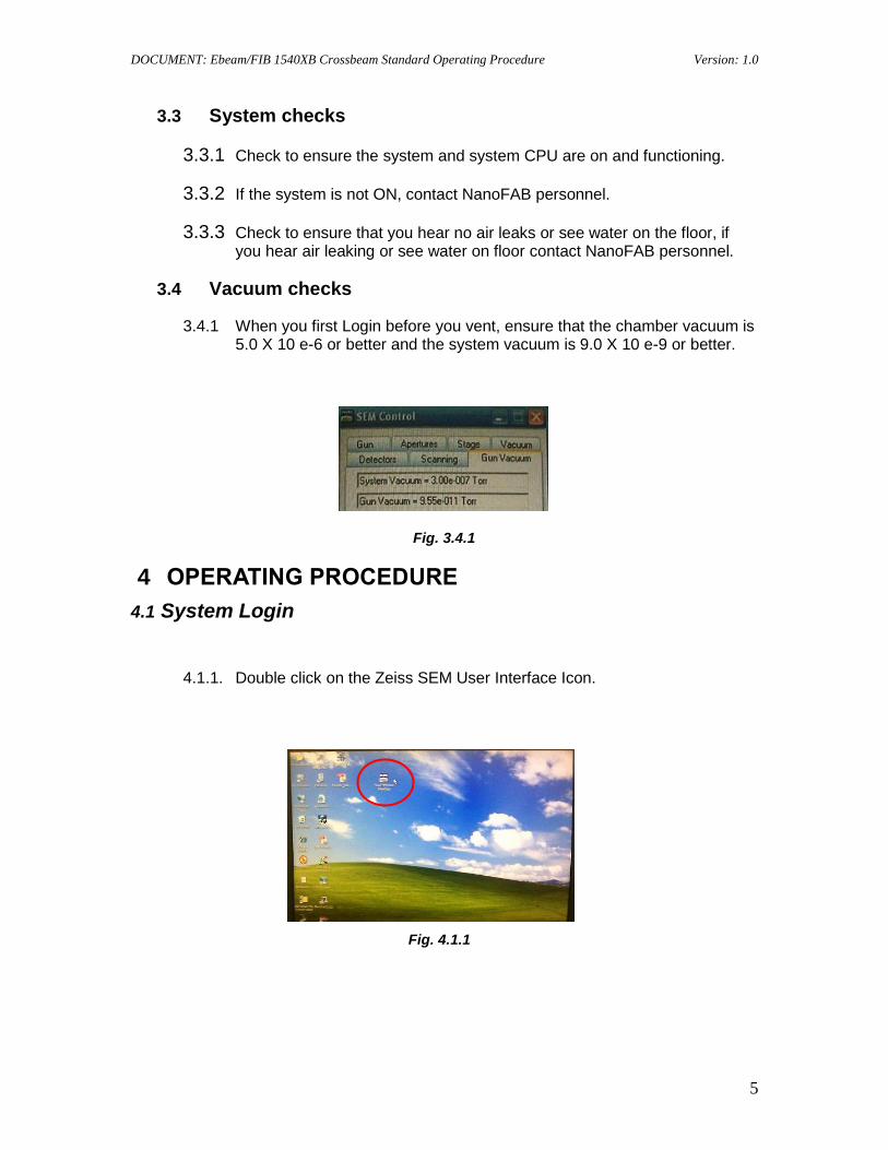
3.4 Vacuum checks
3.4.1 When you first Login before you vent, ensure that the chamber vacuum is 5.0 X 10 e-6 or better and the system vacuum is 9.0 X 10 e-9 or better.
Fig. 3.4.1
4 OPERATING PROCEDURE
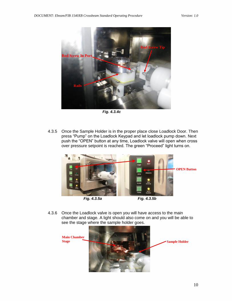
4.1 System Login
4.1.1. Double click on the Zeiss SEM User Interface Icon.
Fig. 4.1.1

DOCUMENT: Ebeam/FIB 1540XB Crossbeam Standard Operating Procedure Version: 1.0
6
4.1.2 An “EM SERVER Log In” box will appear. To login, your ID will be your 1000 number and a password of your choosing.
Fig. 4.1.2
4.1.3 This will bring up the SEM User interface screen as shown below with the camera on, you should be able to see the inside of the chamber.
Fig. 4.1.3
4.1.4 You should open up the SEM control panel from the side bar as shown in Fig 4.1.3 above. The SEM Control appears as below.
Fig. 4.1.4
SEM Column
Side Bar

DOCUMENT: Ebeam/FIB 1540XB Crossbeam Standard Operating Procedure Version: 1.0
7
4.1.5 Once you have checked vacuum under the GUN VACUUM tab of the SEM Control Panel. You are now ready to vent the system to insert your sample/specimen once it has been properly mounted on one of the sample holders.
4.2. Sample/ Specimen Holder Mounting
4.2.1 Choose one of the available sample holder mounts. Use Latex Gloves.
Fig. 4.2.1
4.2.2 Next attach your sample onto one of the sample holders using the provided material or your own carbon or copper tape. Use the air gun to attempt to blow the sample off, if it stays in place it can now be attached to the sample holder mount. Place a scratch directly in the center at the top of the sample.
Fig. 4.2.2
4.2.3 Seat the sample holder pin into the appropriate hole and screw the set screw into place and lightly tighten.
Fig. 4.2.3 Fig. 4.2.3a

DOCUMENT: Ebeam/FIB 1540XB Crossbeam Standard Operating Procedure Version: 1.0
8
Fig. 4.2.3b Fig. 4.2.3c
Fig. 4.2.3d
4.3. Loadlock Vent and Pumpdown
4.3.1 Push “Purge” on loadlock keypad and keep on the N2 purge (Green Light on button On) till you can open the loadlock door. Then push the “Purge” button again to turn off (Green Light on button Off) the N2 purge.
Fig. 4.3.1
Loadlock Door
Purge
Set Screw

DOCUMENT: Ebeam/FIB 1540XB Crossbeam Standard Operating Procedure Version: 1.0
9
4.3.2 Open the loadlock door, be careful of loading rod so that it does not hit the monitor.
Fig. 4.3.2
4.3.3 Slide your sample mount onto the plastic rails.
Fig. 4.3.3a Fig. 4.3.3b
4.3.4 Also ensure that you have the Sample Holder rod screw in port facing the rod screw.
Fig. 4.3.4a Fig. 4.3.4b
Careful
Loadlock Door
Open Position
Plastic Rails
Rail on Holder that slides
onto Plastic Rails
Holder viewed Upside Down
Rod Screw In Port
Rod Screw In Port
DOCUMENT: Ebeam/FIB 1540XB Crossbeam Standard Operating Procedure Version: 1.0
10
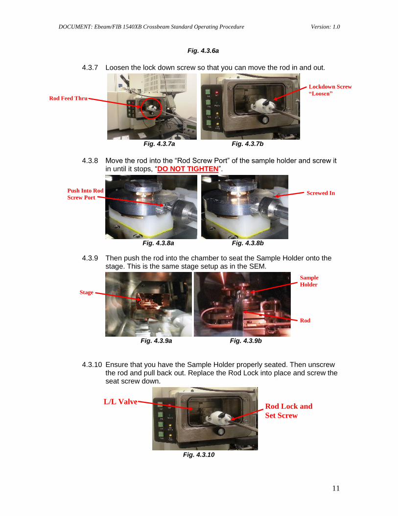
Fig. 4.3.4c
4.3.5 Once the Sample Holder is in the proper place close Loadlock Door. Then press “Pump” on the Loadlock Keypad and let loadlock pump down. Next push the “OPEN” button at any time, Loadlock valve will open when cross over pressure setpoint is reached. The green “Proceed” light turns on.
Fig. 4.3.5a Fig. 4.3.5b
4.3.6 Once the Loadlock valve is open you will have access to the main chamber and stage. A light should also come on and you will be able to see the stage where the sample holder goes.
Main Chamber
Stage
OPEN Button
Sample Holder
Rod Screw In Port
Rails
Rod Screw Tip
DOCUMENT: Ebeam/FIB 1540XB Crossbeam Standard Operating Procedure Version: 1.0
11
Fig. 4.3.6a
4.3.7 Loosen the lock down screw so that you can move the rod in and out.
Fig. 4.3.7a Fig. 4.3.7b
4.3.8 Move the rod into the “Rod Screw Port” of the sample holder and screw it
in until it stops, “DO NOT TIGHTEN”.
Fig. 4.3.8a Fig. 4.3.8b
4.3.9 Then push the rod into the chamber to seat the Sample Holder onto the stage. This is the same stage setup as in the SEM.
Fig. 4.3.9a Fig. 4.3.9b
4.3.10 Ensure that you have the Sample Holder properly seated. Then unscrew the rod and pull back out. Replace the Rod Lock into place and screw the seat screw down.
Fig. 4.3.10
Rod Feed Thru
Lockdown Screw
“Loosen”
Push Into Rod
Screw Port Screwed In
Stage
Sample
Holder
Rod
Rod Lock and
Set Screw
L/L Valve

DOCUMENT: Ebeam/FIB 1540XB Crossbeam Standard Operating Procedure Version: 1.0
12
4.3.11 Next push the “OPEN” button on the Loadlock Keypad to turn off the light. Then push the “CLOSE” button to turn on the light and activate the closing of the Loadlock Valve.
Fig. 4.3.11
4.3.12 Next push the “PURGE” button on the Loadlock Keypad on the Loadlock Keypad for 5 seconds then turn off.
4.3.13 Go to the computer and the SEM user interface for a semi auto load function via the “Airlock” sub panel that can be accessed via the sidebar on the left screen.
Fig. 4.3.13
4.3.14 Once Stage and Sample Holder are ready and Loadlock valve is closed turn the “CLOSE” off on the Loadlock Keypad. Then go to the “AIRLOCK” sub panel and mouse over to the “Resume Exchange” and click on it.
CLOSE
Side Bar
Airlock
Sub Panel

DOCUMENT: Ebeam/FIB 1540XB Crossbeam Standard Operating Procedure Version: 1.0
13
Fig. 4.3.14
4.3.15 Go to SEM Control Panel under the STAGE tab and uncheck the “Protected Z” box.
Fig. 4.3.15
4.3.16 This will move the stage to a predetermined macro setting stage start position in the chamber where you will start getting your initial image on the Ebeam/FIB SEM.
4.4. SEM Operation
4.4.1 Move the stage up/down with the joystick left control pushing forward or back for the “Z” direction and left or right for Tilt . Right control X direction
Resume
Exchange
Protected Z
DOCUMENT: Ebeam/FIB 1540XB Crossbeam Standard Operating Procedure Version: 1.0
14
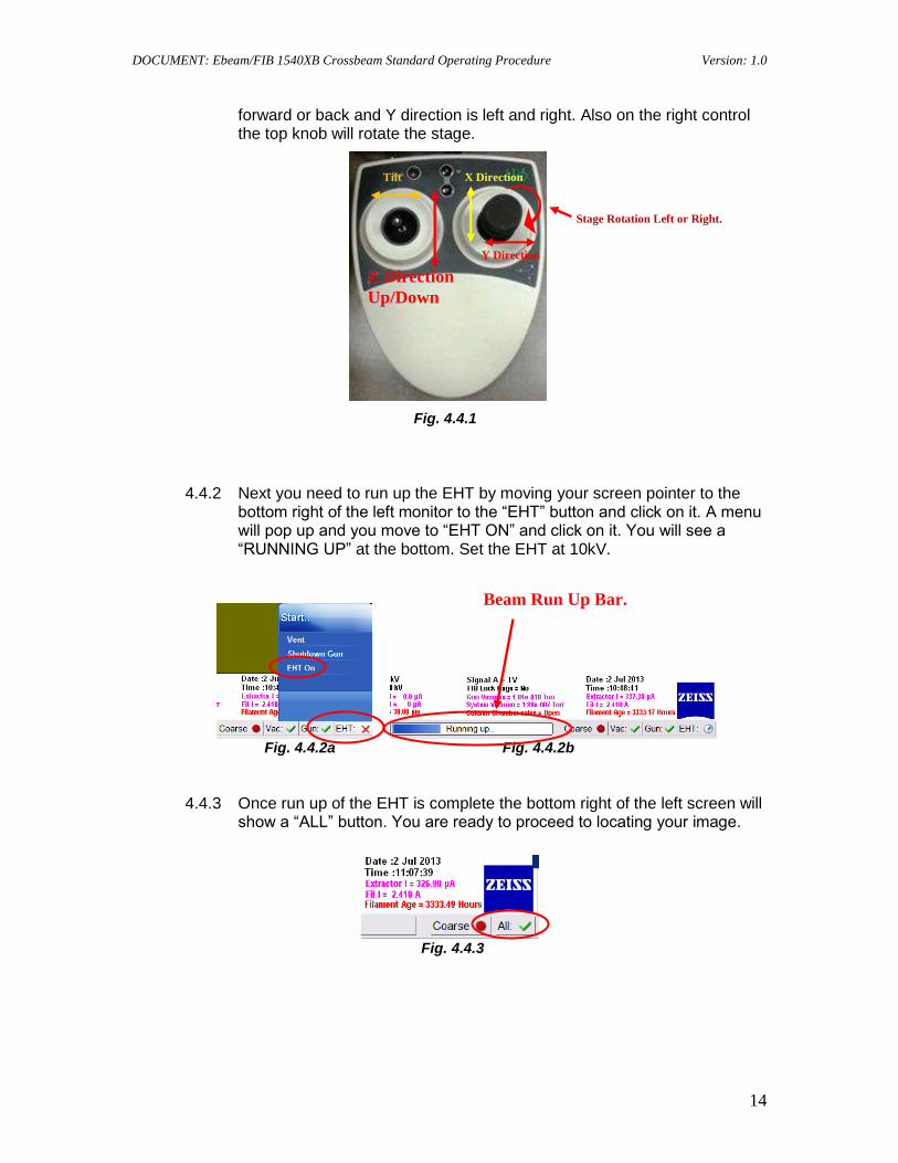
forward or back and Y direction is left and right. Also on the right control the top knob will rotate the stage.
Fig. 4.4.1
4.4.2 Next you need to run up the EHT by moving your screen pointer to the bottom right of the left monitor to the “EHT” button and click on it. A menu will pop up and you move to “EHT ON” and click on it. You will see a “RUNNING UP” at the bottom. Set the EHT at 10kV.
Fig. 4.4.2a Fig. 4.4.2b
4.4.3 Once run up of the EHT is complete the bottom right of the left screen will show a “ALL” button. You are ready to proceed to locating your image.
Fig. 4.4.3
Z Direction
Up/Down
Beam Run Up Bar.
X Direction
Y Direction
Stage Rotation Left or Right.
Tilt
DOCUMENT: Ebeam/FIB 1540XB Crossbeam Standard Operating Procedure Version: 1.0
15
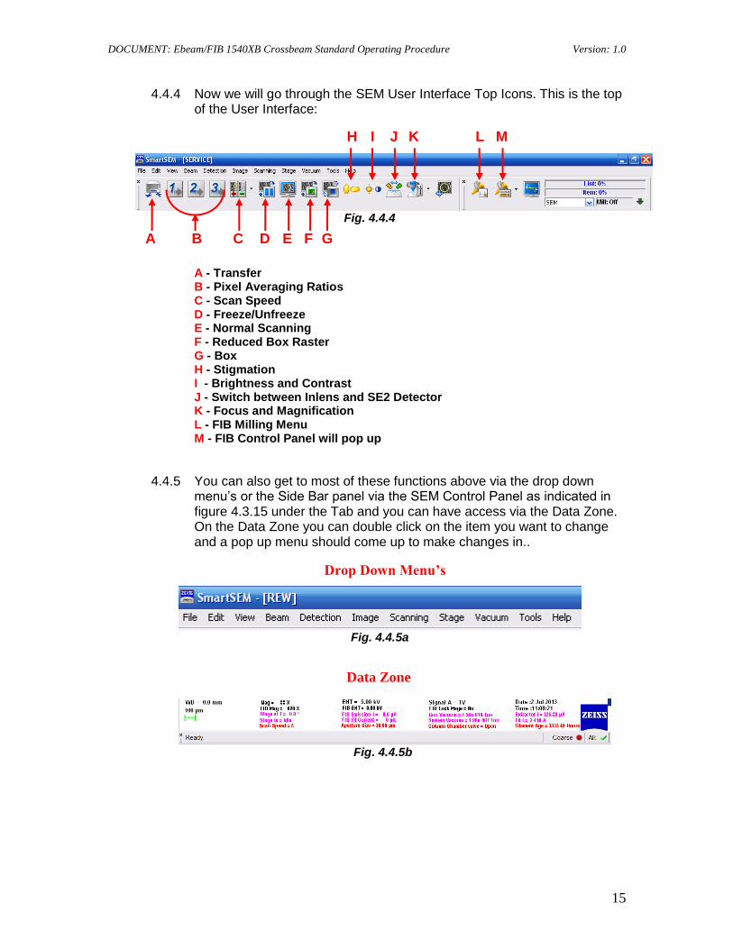
4.4.4 Now we will go through the SEM User Interface Top Icons. This is the top of the User Interface:
Fig. 4.4.4
A - Transfer B - Pixel Averaging Ratios C - Scan Speed D - Freeze/Unfreeze E - Normal Scanning F - Reduced Box Raster G - Box H - Stigmation I - Brightness and Contrast J - Switch between Inlens and SE2 Detector K - Focus and Magnification L - FIB Milling Menu M - FIB Control Panel will pop up
4.4.5 You can also get to most of these functions above via the drop down menu’s or the Side Bar panel via the SEM Control Panel as indicated in figure 4.3.15 under the Tab and you can have access via the Data Zone. On the Data Zone you can double click on the item you want to change and a pop up menu should come up to make changes in..
Fig. 4.4.5a
Fig. 4.4.5b
Drop Down Menu’s
Data Zone
A B C D E F G
H I J K L M
DOCUMENT: Ebeam/FIB 1540XB Crossbeam Standard Operating Procedure Version: 1.0
16
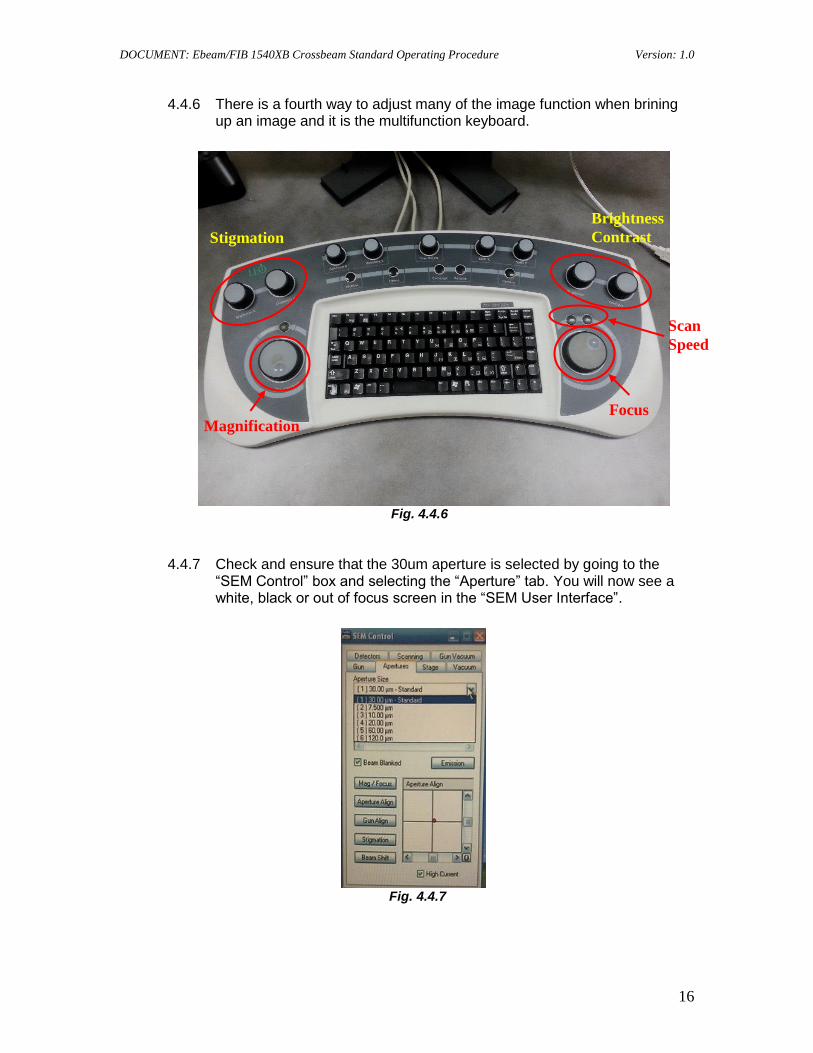
4.4.6 There is a fourth way to adjust many of the image function when brining up an image and it is the multifunction keyboard.
Fig. 4.4.6
4.4.7 Check and ensure that the 30um aperture is selected by going to the “SEM Control” box and selecting the “Aperture” tab. You will now see a white, black or out of focus screen in the “SEM User Interface”.
Fig. 4.4.7
Stigmation
Brightness
Contrast
Magnification Focus
Scan
Speed

DOCUMENT: Ebeam/FIB 1540XB Crossbeam Standard Operating Procedure Version: 1.0
17
4.4.8 The first thing you need to do is go to the brightness/contrast button at the top of the “SEM User Interface” and click on it.
Fig. 4.4.8
4.4.9 At the bottom of the “SEM User Interface” there will be two longer buttons appear, left one for brightness and the right (mid) one for contrast. Ensure the “Course” option selected for adjustment.
Fig 4.4.9a Fig 4.4.9b
4.4.10 There are three options to adjust the brightness and contrast:
4.4.10.1 The first way is from the multifunction keyboard in the upper right.
Fig. 4.4.10.1
Course adjustment
button.
Brightness/Contrast
Adjustment

DOCUMENT: Ebeam/FIB 1540XB Crossbeam Standard Operating Procedure Version: 1.0
18
4.4.10.2 The second one is to double click on the corresponding box. This will bring up a box that you can input a number and press “OK”.
Fig. 4.4.10.2
4.4.10.3 The third way is to use the mouse and hold down the left mouse button and drag mouse left or right to increase or decrease the number.
Fig. 4.4.10.3
4.4.10.4 To adjust the “Contrast” select the “Contrast” button as in 4.4.8.1. But for the mouse adjust you must select and hold down the middle button and drag left or right to increase or decrease the number.
Fig. 4.4.10.4

DOCUMENT: Ebeam/FIB 1540XB Crossbeam Standard Operating Procedure Version: 1.0
19
4.4.11 The next steps can be used for “Focus”, “Magnification” and “Stigmation” when selected.
4.4.11.1 Once you have adjusted the brightness and contrast you should have an unfocused view in the “SEM User Interface”. Next you will select the “Focus” button at the top. Select the right (mid) “Focus” button first. Set “Scan Speed” at about “4”.
Fig. 4.4.11.1
4.4.11.2 You will make adjustments as previously described for the brightness and contrast. The only difference is you will use a unfocus-focus-unfocus-focus method. In other words you will go from out of focus to in focus and continue in the same direction you where to get the item in focus till it is out of focus then reverse direction and bring it back into focus to get the best rough focus you can. Using the mouse and pressing on the center button and moving left and right.
4.4.11.3 You can use the multifunction Keyboard by using the lower right big knob and rotate clockwise or counter clockwise.
Fig. 4.4.11.3
4.4.11.4 At this time you will want to go back and set up your stage height. Look at the bottom left of the “SEM User Interface” at the “W.D”. If you will be using the Ebeam you will need to set it up at 6 mm, if you are
Focus
Focus Knob Magnification
Knob (WD)
Stigmation Scan Speed
Scan Speed

DOCUMENT: Ebeam/FIB 1540XB Crossbeam Standard Operating Procedure Version: 1.0
20
using the FIB you will want to set it up at 5 mm WD. Ensure “TRACK Z” is checked in the “SEM Control” panel and then adjust “Z” (stage up and down position) as indicated in 4.4.1 above.
Fig. 4.4.11.4a Fig. 4.4.11.4b
Note: Checking “Track Z” will ensure you maintain the rough focus that you just made!
4.4.11.5 Once you have adjusted your height you may have to come back at later time to tweak it in. Next you will want to perform a course focus by locating something extremely small on the surface, enlarging (Note: stay off the resist surface for Ebeam Lithography) it by clicking on the “Focus” button and choose the left “MAG” (magnification) button or the center mouse button and adjust it till it is close by using the previous procedure in 4.4.10.1.3 moving the mouse left and/or right. Or use the multifunction keyboard and use the large knob at the bottom left for Magnification (WD) and the large knob at the bottom right for Focus. From this point on I will only refer to the multifunction keyboard, same functions can be performed with the mouse and directly with a command box.
Green Check
Mark

DOCUMENT: Ebeam/FIB 1540XB Crossbeam Standard Operating Procedure Version: 1.0
21
4.5 Annotations and Measurements
4.5.1 You can add measurement and annotations to your image. There are two ways you can get to both:
4.5.1.1 You can go to “EDIT” and move down to “Insert Annotation Text”.
Fig. 4.5.1.1
4.5.1.2 When you click on “Annotations” a box will pop up on the screen where you will put your annotations. This is where you will type whatever you need to add to the image.
Fig. 4.5.1.2
4.5.1.3 You can go to “EDIT” and go down to “Annotations”.
Fig. 4.5.1.3
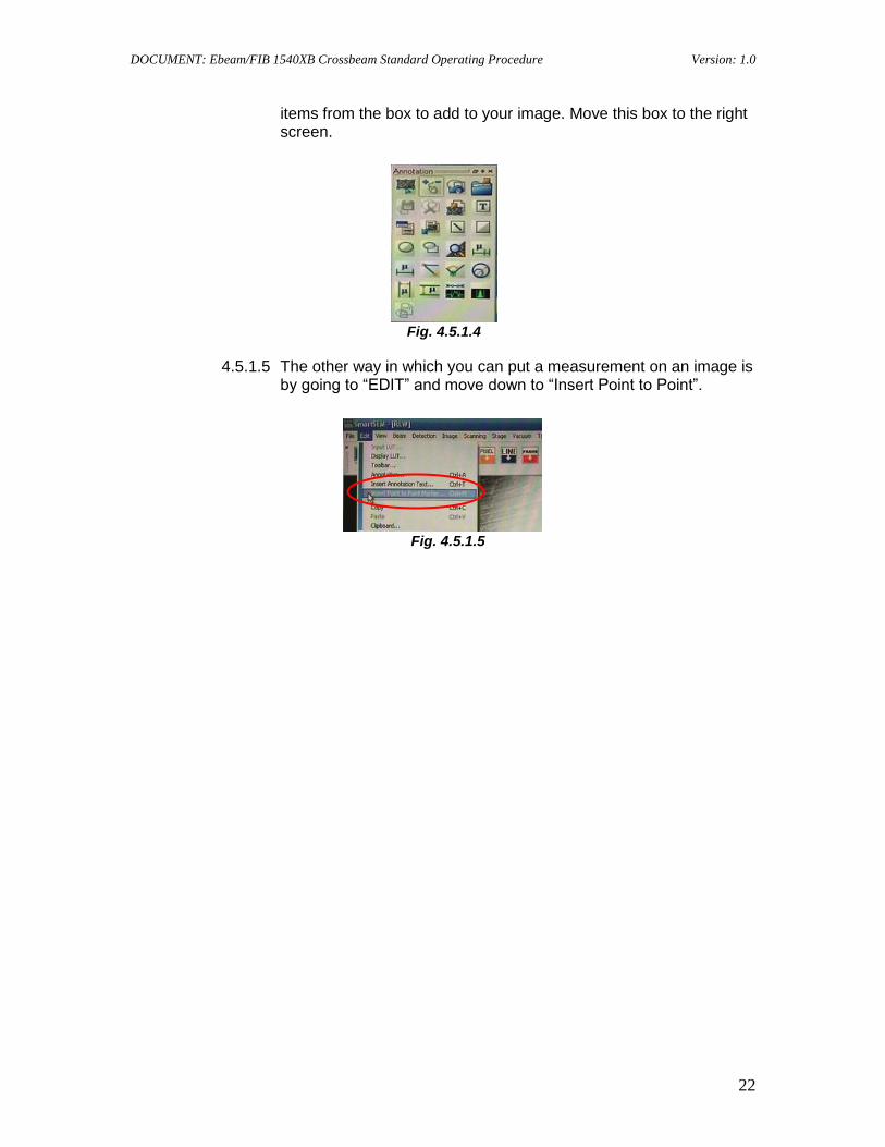
4.5.1.4 A box will pop up that will not only have annotation capabilities but also measurement abilities. This box will stay up and you select
DOCUMENT: Ebeam/FIB 1540XB Crossbeam Standard Operating Procedure Version: 1.0
22
items from the box to add to your image. Move this box to the right screen.
Fig. 4.5.1.4
4.5.1.5 The other way in which you can put a measurement on an image is by going to “EDIT” and move down to “Insert Point to Point”.
Fig. 4.5.1.5
DOCUMENT: Ebeam/FIB 1540XB Crossbeam Standard Operating Procedure Version: 1.0
23
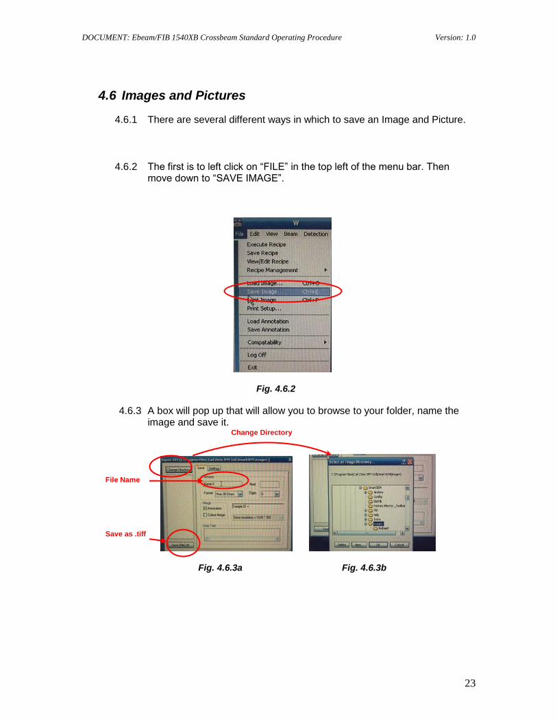
4.6 Images and Pictures
4.6.1 There are several different ways in which to save an Image and Picture.
4.6.2 The first is to left click on “FILE” in the top left of the menu bar. Then move down to “SAVE IMAGE”.
Fig. 4.6.2
4.6.3 A box will pop up that will allow you to browse to your folder, name the image and save it.
Fig. 4.6.3a Fig. 4.6.3b
Change Directory
File Name
Save as .tiff

DOCUMENT: Ebeam/FIB 1540XB Crossbeam Standard Operating Procedure Version: 1.0
24
4.6.4 The other way is to right click on the mouse with the arrow over the image and a box will appear. Move down the box to “SEND TO” and highlight with the arrow and another drop down box will appear.
Fig. 4.6.4
4.6.5 As you can see here you may save the image as a .tiff, .bmp or a .jpg image. Move your arrow over whichever one you would like to save it as then left click on the mouse and a similar box will appear as in 4.7.1.2a.

DOCUMENT: Ebeam/FIB 1540XB Crossbeam Standard Operating Procedure Version: 1.0
25
The only difference is when you save it the save button will indicate which one you are saving as.
Fig. 4.6.5a Fig. 4.6.5b Fig. 4.6.5c
4.6.6 At this point you are ready to move on to Appendix A for Ebeam Lithography or Appendix B for FIB.
Appendix A
Ebeam Lithography
1. Locate the gold sample on the stage and center it, you will want to open a “Reduced Raster” box by going to the top center of the “SEM User Interface” and clicking on the third button from the left, a black box with a GREEN square in it.
Fig. A1
Scan Speed
Reduced Raster Box
Save as .tiff Save as .bmp Save as .jpg
DOCUMENT: Ebeam/FIB 1540XB Crossbeam Standard Operating Procedure Version: 1.0
26
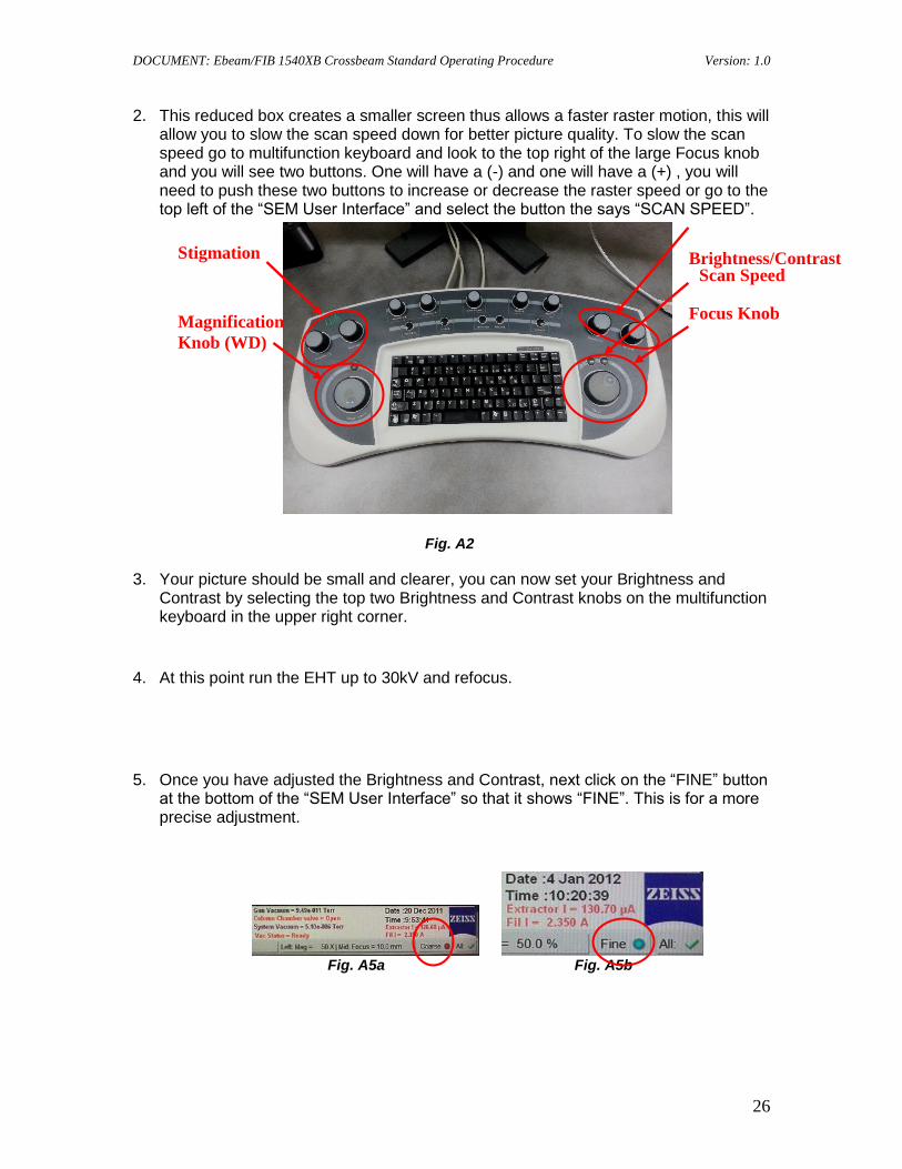
2. This reduced box creates a smaller screen thus allows a faster raster motion, this will allow you to slow the scan speed down for better picture quality. To slow the scan speed go to multifunction keyboard and look to the top right of the large Focus knob and you will see two buttons. One will have a (-) and one will have a (+) , you will need to push these two buttons to increase or decrease the raster speed or go to the top left of the “SEM User Interface” and select the button the says “SCAN SPEED”.
Fig. A2
3. Your picture should be small and clearer, you can now set your Brightness and Contrast by selecting the top two Brightness and Contrast knobs on the multifunction keyboard in the upper right corner.
4. At this point run the EHT up to 30kV and refocus.
5. Once you have adjusted the Brightness and Contrast, next click on the “FINE” button at the bottom of the “SEM User Interface” so that it shows “FINE”. This is for a more precise adjustment.
Fig. A5a Fig. A5b
Focus Knob Magnification
Knob (WD)
Stigmation
Scan Speed Brightness/Contrast
DOCUMENT: Ebeam/FIB 1540XB Crossbeam Standard Operating Procedure Version: 1.0
27
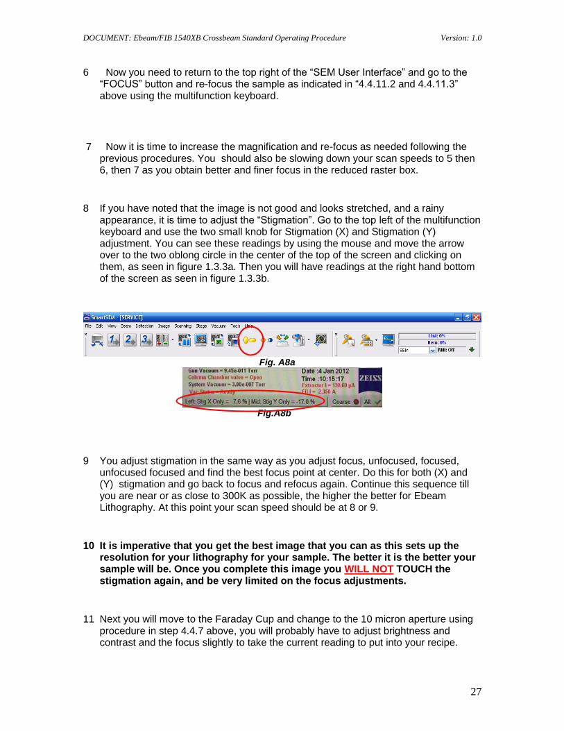
6 Now you need to return to the top right of the “SEM User Interface” and go to the “FOCUS” button and re-focus the sample as indicated in “4.4.11.2 and 4.4.11.3” above using the multifunction keyboard.
7 Now it is time to increase the magnification and re-focus as needed following the previous procedures. You should also be slowing down your scan speeds to 5 then 6, then 7 as you obtain better and finer focus in the reduced raster box.
8 If you have noted that the image is not good and looks stretched, and a rainy appearance, it is time to adjust the “Stigmation”. Go to the top left of the multifunction keyboard and use the two small knob for Stigmation (X) and Stigmation (Y) adjustment. You can see these readings by using the mouse and move the arrow over to the two oblong circle in the center of the top of the screen and clicking on them, as seen in figure 1.3.3a. Then you will have readings at the right hand bottom of the screen as seen in figure 1.3.3b.
Fig. A8a
Fig.A8b
9 You adjust stigmation in the same way as you adjust focus, unfocused, focused, unfocused focused and find the best focus point at center. Do this for both (X) and (Y) stigmation and go back to focus and refocus again. Continue this sequence till you are near or as close to 300K as possible, the higher the better for Ebeam Lithography. At this point your scan speed should be at 8 or 9.
10 It is imperative that you get the best image that you can as this sets up the resolution for your lithography for your sample. The better it is the better your sample will be. Once you complete this image you WILL NOT TOUCH the stigmation again, and be very limited on the focus adjustments.
11 Next you will move to the Faraday Cup and change to the 10 micron aperture using procedure in step 4.4.7 above, you will probably have to adjust brightness and contrast and the focus slightly to take the current reading to put into your recipe.
DOCUMENT: Ebeam/FIB 1540XB Crossbeam Standard Operating Procedure Version: 1.0
28
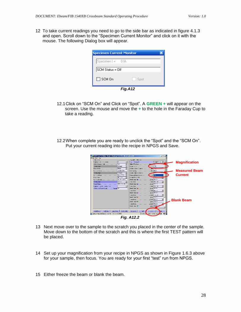
12 To take current readings you need to go to the side bar as indicated in figure 4.1.3 and open. Scroll down to the “Specimen Current Monitor” and click on it with the mouse. The following Dialog box will appear.
Fig.A12
12.1 Click on “SCM On” and Click on “Spot”. A GREEN + will appear on the screen. Use the mouse and move the + to the hole in the Faraday Cup to take a reading.
12.2 When complete you are ready to unclick the “Spot” and the “SCM On”. Put your current reading into the recipe in NPGS and Save.
Fig. A12.2
13 Next move over to the sample to the scratch you placed in the center of the sample. Move down to the bottom of the scratch and this is where the first TEST pattern will be placed.
14 Set up your magnification from your recipe in NPGS as shown in Figure 1.6.3 above for your sample, then focus. You are ready for your first “test” run from NPGS.
15 Either freeze the beam or blank the beam.
Measured Beam
Current
Blank Beam
Magnification

DOCUMENT: Ebeam/FIB 1540XB Crossbeam Standard Operating Procedure Version: 1.0
29
Fig. A15a Fig. A15b
16 Go to the NPGS computer and click on “NPGS Mode”. This puts the NPGS computer in control of the beam with the beam blanker.
Fig. A16
17 Turn the Beam Blanker on and ensure the BLUE selector switch is on SEM.
18 You may either go to “Process Run File” on the top left of the NPGS screen as shown in Figure 1.8 above or on the mouse right click and choose from the pop up menu “Process Run File” as shown below.
Freeze
Blank Beam
NPGS Mode

DOCUMENT: Ebeam/FIB 1540XB Crossbeam Standard Operating Procedure Version: 1.0
30
Fig. A18
19 The following screen on the NPGS computer will appear.
Fig. A19
20 If more than 24 hours since the last use you may get this screen first over the top of the previous screen. There is nothing to worry about, it is a 40 second calibration of the DAC’s and it is normal.
Fig. A20
Process Run
File
DOCUMENT: Ebeam/FIB 1540XB Crossbeam Standard Operating Procedure Version: 1.0
31
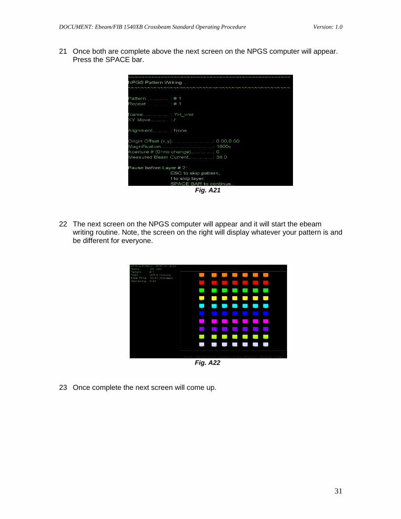
21 Once both are complete above the next screen on the NPGS computer will appear. Press the SPACE bar.
Fig. A21
22 The next screen on the NPGS computer will appear and it will start the ebeam writing routine. Note, the screen on the right will display whatever your pattern is and be different for everyone.
Fig. A22
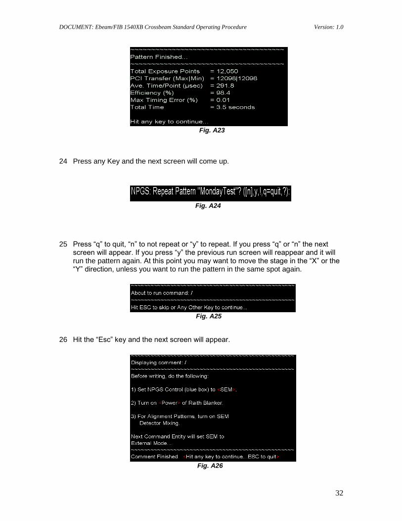
23 Once complete the next screen will come up.
DOCUMENT: Ebeam/FIB 1540XB Crossbeam Standard Operating Procedure Version: 1.0
32
Fig. A23
24 Press any Key and the next screen will come up.
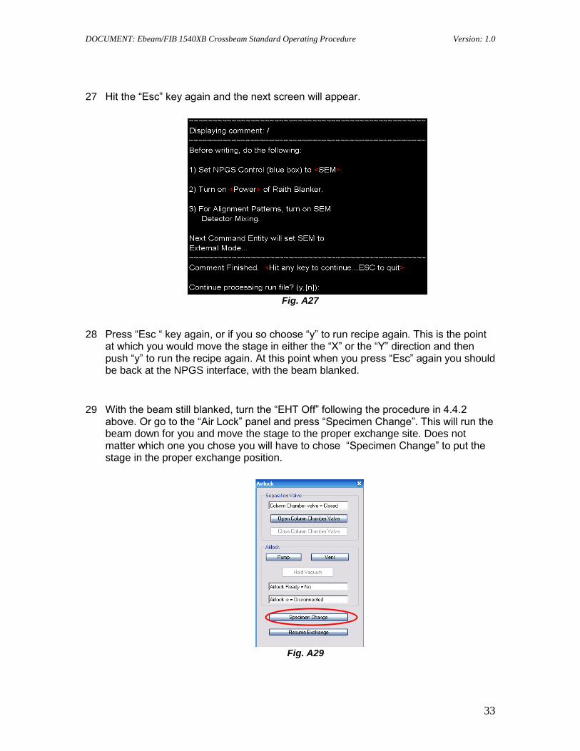
Fig. A24
25 Press “q” to quit, “n” to not repeat or “y” to repeat. If you press “q” or “n” the next screen will appear. If you press “y” the previous run screen will reappear and it will run the pattern again. At this point you may want to move the stage in the “X” or the “Y” direction, unless you want to run the pattern in the same spot again.
Fig. A25
26 Hit the “Esc” key and the next screen will appear.
Fig. A26
DOCUMENT: Ebeam/FIB 1540XB Crossbeam Standard Operating Procedure Version: 1.0
33
27 Hit the “Esc” key again and the next screen will appear.
Fig. A27
28 Press “Esc “ key again, or if you so choose “y” to run recipe again. This is the point at which you would move the stage in either the “X” or the “Y” direction and then push “y” to run the recipe again. At this point when you press “Esc” again you should be back at the NPGS interface, with the beam blanked.
29 With the beam still blanked, turn the “EHT Off” following the procedure in 4.4.2 above. Or go to the “Air Lock” panel and press “Specimen Change”. This will run the beam down for you and move the stage to the proper exchange site. Does not matter which one you chose you will have to chose “Specimen Change” to put the stage in the proper exchange position.
Fig. A29

DOCUMENT: Ebeam/FIB 1540XB Crossbeam Standard Operating Procedure Version: 1.0
34
30 Once the stage is in the exchange position, “PUMP” the Loadlock and reverse the follow the procedure in 4.3.5 to 4.3.11 and remove the sample from the chamber.
31 Once in the Loadlock, ensure all the button are off (not lit). Then push the “VENT” button till vented, open the door and turn off the “VENT”. Remove Sample, close door and start “PUMP” till you hear the second click of the valves and wait 10 seconds and turn off the “PUMP”.
32 Remove sample from holder, clean sample holder. Log into logbook your time. Log off the tool and clean up the area.
Appendix B
FIB Operation
1 Open the “FIB Control” Panel.
Fig. B1
2 Next Un-Click “Regulate” in Figure B1 Then turn “Gun On” as indicated in Figure B1 above.
Regulate
Gun Off
Emission Current
Extraction Target
Suppression Target

DOCUMENT: Ebeam/FIB 1540XB Crossbeam Standard Operating Procedure Version: 1.0
35
3 Once “ON” monitor, You will probably have to adjust the “Extraction Target” and
the “Suppression Target” till the “Emission Current” stabilizes at 2.0uA.
4 You will see the “Emission Current” go from white to yellow to green to
sometimes red and oscillate between these colors as it stabilizes. Note that if it goes red and you see 49uA and it goes white with 0.0uA it is in an overcurrent state. It actually is sending more current that 49uA, just our readout only goes to 49uA. At this point to need to reverse you adjustments and slowly bring it back down.
5 If the “Suppression Target” maxes out and you can not control by the “Extraction
Target”, the FIB needs a “Preheat Routine” ran. Anytime you go over 7.25kV on the “Extraction Target” and it will not start reducing after warm up period, the FIB need a “Preheat Routine” ran.
6 Once the FIB has stabilized for about 5 minutes you can re-check the “Regulate”
box. Monitor to ensure there is not to much oscillation.
7 Once you are at 5mm WD (+/- .1 mm ), you are ready to start the tilt operation. Have the SEM Control Panel up with the Stage Panel showing to perform this operation. You may use either the SE2 or the Inlens Detectors, which ever one you were using to get you picture. You will be switching between TV and the Detector you are using to ensure you maintain focus and don't damage the tool or your sample.
Fig. B7
8 Click on the “GoTo” for the “Z” and a sub panel will pop up. Insert 5 for 5 degrees and check your focus item and go to TV and check the SEM and FIB and ensure proper clearance. Then go to 10, then 15 then 20 all the way to 54 degrees. Each time checking you focus spot under the detector and making stage adjustments
DOCUMENT: Ebeam/FIB 1540XB Crossbeam Standard Operating Procedure Version: 1.0
36
to keep it centered and focused and check the TV for proper clearance in the chamber.
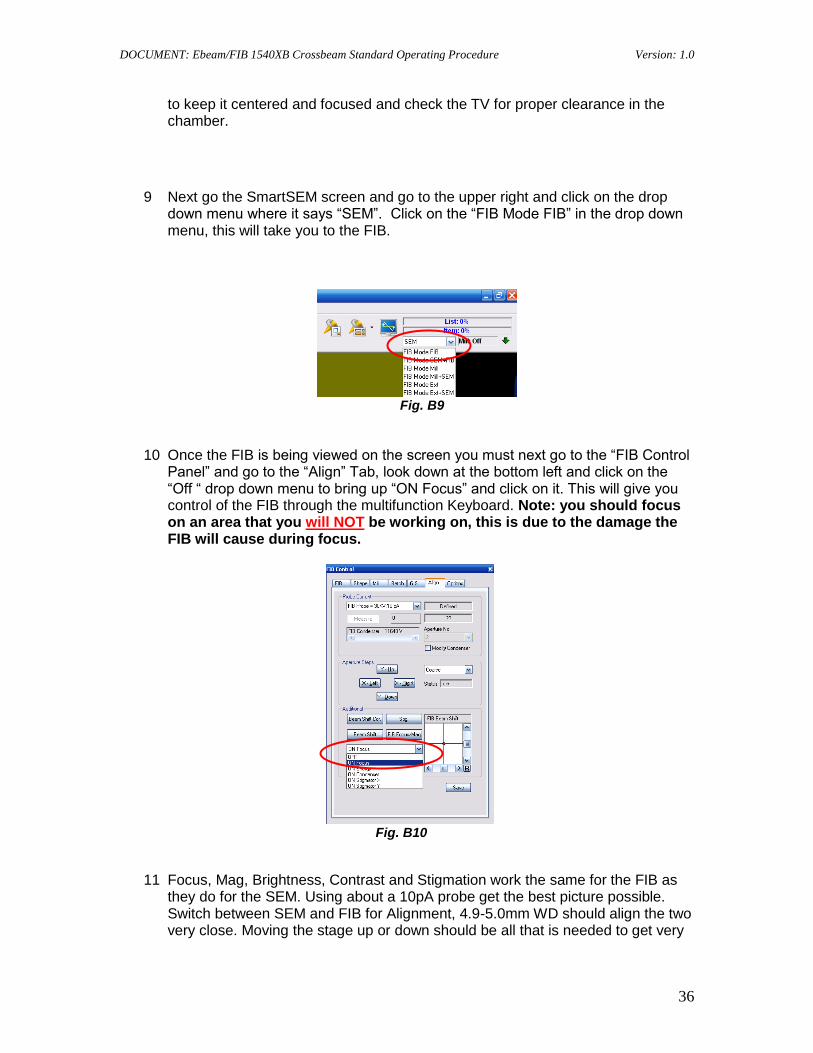
9 Next go the SmartSEM screen and go to the upper right and click on the drop
down menu where it says “SEM”. Click on the “FIB Mode FIB” in the drop down menu, this will take you to the FIB.
Fig. B9
10 Once the FIB is being viewed on the screen you must next go to the “FIB Control Panel” and go to the “Align” Tab, look down at the bottom left and click on the “Off “ drop down menu to bring up “ON Focus” and click on it. This will give you control of the FIB through the multifunction Keyboard. Note: you should focus on an area that you will NOT be working on, this is due to the damage the FIB will cause during focus.
Fig. B10
11 Focus, Mag, Brightness, Contrast and Stigmation work the same for the FIB as they do for the SEM. Using about a 10pA probe get the best picture possible. Switch between SEM and FIB for Alignment, 4.9-5.0mm WD should align the two very close. Moving the stage up or down should be all that is needed to get very

DOCUMENT: Ebeam/FIB 1540XB Crossbeam Standard Operating Procedure Version: 1.0
37
close to being aligned between the two or at least on the same screen between the two.
12 Once they are aligned and you have a good picture click on “FIB Lock MAGs”=
Yes (This locks SEM and FIB magnification together), move the stage over to the area you want to work on, it should be close by. There are a couple of ways to perform the work with the FIB you need to do. Which one you choose is up to you. 12.1 The first one is from the top right of the SmartSEM menu bar as shown
below in Figure B12.1
Fig. B12.1
12.2 Once you pick the object go to “FIB Control” under the “Shape” Tab and choose the Milling Mode – usually Mill For Time, then chose the amount of Time in seconds, then choose the Milling Current as seen below.
Fig. B12.2
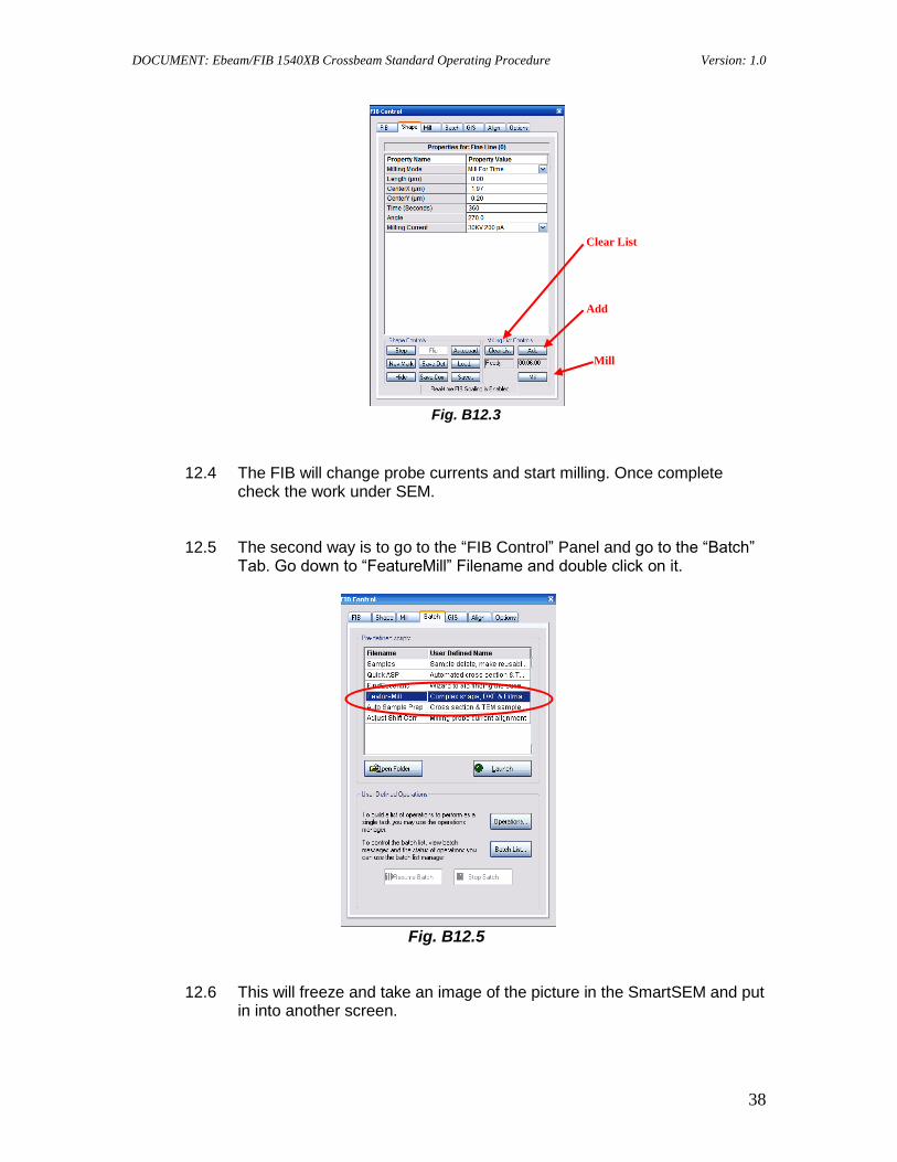
12.3 On the same Tab you will need to click on the “Clear List” and “Add” buttons. Then click on the “Mill” button when ready to start.
Milling Mode
Time
Milling Current
Time
DOCUMENT: Ebeam/FIB 1540XB Crossbeam Standard Operating Procedure Version: 1.0
38
Fig. B12.3
12.4 The FIB will change probe currents and start milling. Once complete
check the work under SEM.
12.5 The second way is to go to the “FIB Control” Panel and go to the “Batch” Tab. Go down to “FeatureMill” Filename and double click on it.
Fig. B12.5
12.6 This will freeze and take an image of the picture in the SmartSEM and put in into another screen.
Clear List
Add
Mill
DOCUMENT: Ebeam/FIB 1540XB Crossbeam Standard Operating Procedure Version: 1.0
39
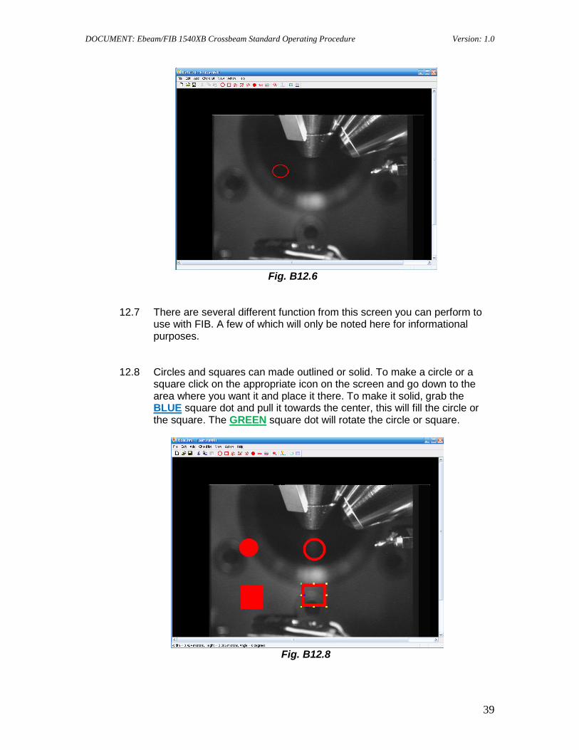
Fig. B12.6
12.7 There are several different function from this screen you can perform to use with FIB. A few of which will only be noted here for informational purposes.
12.8 Circles and squares can made outlined or solid. To make a circle or a square click on the appropriate icon on the screen and go down to the area where you want it and place it there. To make it solid, grab the BLUE square dot and pull it towards the center, this will fill the circle or the square. The GREEN square dot will rotate the circle or square.
Fig. B12.8

DOCUMENT: Ebeam/FIB 1540XB Crossbeam Standard Operating Procedure Version: 1.0
40
12.9 You can import a saved .bmp feature by clicking on . Or you can enter
text to be written by clicking on . Click on to bring up the milling feature for the FIB. You can enter milling time and probe current and OK to start.
Fig. B12.9
13 Once you have milled a site, the tool will automatically go to SEM mode. You can
then check your work and if you have more work follow the previous steps in 12. If you are done you are ready to shut the FIB down and unload.
14 Go to the “FIB Control” Panel and go to the “FIB” tab and go to the “On” button and click on it to turn the FIB off.
15 Next, go to the “SEM Control” Panel and go to the “Stage” tab and reverse the
procedure in step 8 above. Once at 0 degrees tilt you are ready for normal unload procedure.
16 On the “Airlock Control” Panel and click on “Specimen Change”.
Fig. B16
Time
Probe Current
OK – To Start

DOCUMENT: Ebeam/FIB 1540XB Crossbeam Standard Operating Procedure Version: 1.0
41
17 Once the stage is in the exchange position, “PUMP” the Loadlock and reverse the follow the procedure in 4.3.5 to 4.3.11 and remove the sample from the chamber.
18 Once in the Loadlock, ensure all the button are off (not lit). Then push the
“VENT” button till vented, open the door and turn off the “VENT”. Remove Sample, close door and start “PUMP” till you hear the second click of the valves and wait 10 seconds and turn off the “PUMP”.
19 Remove sample from holder, clean sample holder. Log into logbook your time. Log off the tool and clean up the area.