east penn traction clubeastpenn.org/articles/ho_trolley_modif_clinic_v4_oct2015.pdf · east penn...
TRANSCRIPT

East Penn Traction Club
Michael Junod
10/22/2015
10/22/2015 1

East Penn Traction Club
Many HO scale Ready-to-Run (RTR) models (particularly older brass imports) will not provide satisfactory performance for the serious trolley modeler. Trolleys are not wired for overhead operation
If wired, not wired for pole reverse
Trolley poles do not pivot freely and have poor overhead contact and tracking
Trolley car will not negotiate prototype streetcar curves (6” radius)
Trolley has poor slow speed operation Open frame motors
4 wheel (alternate truck) pickup
10/22/2015 2

East Penn Traction Club
Typical Brass Import Suydam Niles Freight Motor
1960’s vintage
Oregon Electric Prototype
10/22/2015 3

East Penn Traction Club
Replace trolley pole bases with insulated bushing and brass pivot base
Replace trolley poles with “pin base” trolley poles
Wire trolley for pole reverse using 3 pin connectors for easy car disassembly.
Modify power truck to increase angle of rotation and decrease minimum radius
Add wipers to insulated wheels for 8 wheel pickup
Replace open frame motor with can motor and flywheel assembly
Add diodes to reduce the speed of this faster trolley into the “fleet speed” range
10/22/2015 4

East Penn Traction Club
These modifications are for DC operation.
Nothing in this clinic precludes installing a DCC decoder Pole Reverse capability is lost with DCC
Diode installation not necessary with DCC
The nuances of rewiring cars for DCC operation is covered in other clinics. East Penn Clinic “DCC Clinic” by Dave Gairo
Trolleyville Schoolhouse Clinic “Digital Command Control and Overhead Trolley Wire Operation” by George Huckaby and John McWhirter
10/22/2015 5

East Penn Traction Club
Trolley Pole Bases The trolley poles on many RTR
trolleys come with a threaded base and are attached to the trolley through an insulated bushing (if the body is metal) and a solder lug for electrical connection and a nut. Electrical connection to the
pole is made by soldering a wire to the solder lug.
The mass and stiffness of this wire, no matter how small a gauge, can restrict the free swing of the pole and cause dewirements.
If the pole needs to be replaced or serviced, the car must be disassembled to undo the hardware to remove the pole.
Trolley Pole Base
10/22/2015 6

East Penn Traction Club
Trolley Pole Bases Replace existing pole base structure with brass pivot capable of
accepting “pin” based trolley poles
Insulated bushing and brass pivot
Expand trolley base hole to #27 Hole
Super glue insulated bushing into hole
Insure bushing is flush and level
Super glue brass pivot into bushing
Insure fully seated and perpendicular to roofline
Do not get super glue inside pivot
Solder electrical leads to outside of brass pivot
All new Bowser trolleys come with Brass pivot and pin based poles 10/22/2015 7

East Penn Traction Club
Materials
Available from Custom Traxx
Insulated Bushing
Part # SCTC-2
Brass Pivot
Part #SCTC-1 or
Bowser Part #12508
10/22/2015 8

East Penn Traction Club
Original Trolley Base Holes approx #46 or 0.081”
10/22/2015 9

East Penn Traction Club
Resized Holes #27 or 0.144”
Open trolley base holes by going up 2 drill sizes at a time (i.e. #44, #42, #40..) to avoid damaging roofwalk.
10/22/2015 10

East Penn Traction Club
Insulated bushings glued in place.
Slide pivot partway into bushing, apply superglue, and push in all the way.
10/22/2015 11

East Penn Traction Club
10/22/2015 12

East Penn Traction Club
Trolley Pole Shoes/Wheels The trolley poles on many
RTR trolleys come with a shoe or wheel that is un-prototypical in shape and size and provides poor performance “Taco” shoe – a piece of
metal wrapped around the pole and soldered
The solder connecting the shoe to the pole often comes in contact with the overhead making the overhead dirty and wearing the shoe/pole joint.
10/22/2015 13

East Penn Traction Club
Trolley Pole Springs When using functioning
overhead wire, the most unreliable connection in the propulsion circuit is between the trolley pole and the overhead. Single point contact vs 8
wheel (hopefully) rail pickup Strong upward pressure from
the trolley pole is necessary to maintain reliable contact with the overhead
Many RTR trolley poles have moderate (at best) upward pressure and can easily lose springs further decreasing the upward pressure
10/22/2015 14

East Penn Traction Club
Trolley Pole Replacement Replace existing trolley poles with “Miniatures by Eric” trolley
poles Very strong upward pressure Does not lose springs Poles feature simulated slider shoe or wheel castings
Solid casting No solder contact with overhead Longer wear.
Pin base Freely rotates, tracks better, fewer dewirements Easy removal for cleaning, adjusting
Rich Eaton also makes very fine poles with good upward pressure. Better (smaller) wheel casting than Miniatures by Eric.
Pin New Bowser PCC (Form 11) pole is made from “Miniatures by Eric” design
10/22/2015 15

East Penn Traction Club
Reverse pole base Miniatures by Eric
Forward pole base Miniatures by Eric
Forward pole base Rich Eaton
“Wheel” type slider Rich Eaton “Wheel” type slider
Miniatures by Eric
“Shoe” type slider Miniatures by Eric
Brass pole Rich Eaton
Piano wire pole Miniatures by Eric
Cast sliders No solder contact to
overhead
Strong springs that don’t fall off insure good overhead contact
10/22/2015 16

East Penn Traction Club
Trolley Pole Reverse
The most obvious method to wire trolleys for overhead operation is to remove the positive wire from one of the trucks and attach it to both pole bases (if a double ended car)
Some cars come from the factory wired this way
To reverse the car the polarity of the wire and rail must be reversed
This is not feasible in a system where multiple cars are being run simultaneously from a single power source.
10/22/2015 17

East Penn Traction Club
Trolley Pole Reverse For proper operation
attach the positive lead from the motor to the “up” pole base for forward travel
Attach the negative motor lead to the “down” pole base
Attach a wire from the metal body to the metal frame or from both hold down hooks to the metal frame
Attach a wire from the metal frame to all pickup wheels.
From East Penn clinic “Model Trolley Car Wiring”
By Richard Kerr
10/22/2015 18

East Penn Traction Club
Car Disassembly
If the leads from the trolley pole bases and body are hard wired to the frame and motor, it can be difficult to work on either portion of the trolley when disassembled.
10/22/2015 19

East Penn Traction Club
Car Disassembly Install Miniatronics
micro-mini 3 pin connector Standardized wiring
Allows interchange of bodies and frames if you have many cars of the same type/model.
Allows testing of power train without body using test tether.
Small design only slightly larger than wire itself.
10/22/2015 20

East Penn Traction Club
Standard Wiring Diagram using 3 pin connector.
10/22/2015 21

East Penn Traction Club
White dot and white stripe aid in pin/plug registration
Worse case, if pugged in backward, trolley runs in
reverse
Male and Female connectors are NOT “keyed”
10/22/2015 22

East Penn Traction Club
On double end cars, designate and mark one end as the front (forward) If car is metal and painted or oxidized burnish an area on
the underside of the roof to solder the body/frame wire
Tin connector wire and loop around pole base
“Forward” pole “Reverse” pole Body
Finished connector installation 10/22/2015 23

East Penn Traction Club
Rail Pickup
Many RTR trolleys (2 truck) come with 4 wheel pickup and wired for two rail operation.
Usually one truck picks up from one rail and the other truck from the other rail.
One wheel on each axle is insulated from the rest of the axle.
Additional wheel pickups can improve operation in dirty rail situations and improve the detection of the trolley in automatic train control systems.
10/22/2015 24

East Penn Traction Club
8 Wheel Rail Pickup
Install wire wheel wipers on each truck.
26 Gauge phosphor bronze overhead wire
Bend wire into “V” shape
Solder wire to truck frame so wire gently wipes the insulated wheel
Back of wheel for trailing truck
Wheel tread for power truck
Verify free wheel rotation
10/22/2015 25

East Penn Traction Club
Phosphor Bronze wire soldered to frame of power truck wiping the
tread of the insulated wheels
10/22/2015 26

East Penn Traction Club
Phosphor Bronze wire soldered to frame of trailing truck wiping the
back of the insulated wheels
10/22/2015 27

East Penn Traction Club
Turning Radius The turning radius of many RTR is sufficient to negotiate
a 9” radius curve (65’ prototype radius). The minimum radius of many layouts is 6” (43’ prototype
radius) and a lot closer to the 50’-37’ radius seen on city curves.
Most trolleys have a single power truck and a trailing truck.
Usually, unless blocked by steps or underbody detail, the trailing truck will swing through a large angular range
The power truck usually limits the minimum turning radius by one or more of the following features: Power truck design Through the floor mounting Motor / Power Truck coupling
10/22/2015 28

East Penn Traction Club
Turning Radius
Remove trolley frame from body
Use a minimum radius test curve to verify car will not negotiate minimum curve
Determine limiting mechanical factor
Remediation depends on power train design
Gear Tower
Spring Belt
10/22/2015 29

East Penn Traction Club
Turning Radius (Gear Tower)
In “Gear Tower” power trains, the truck gear box or the opening in the floor for the truck and gear box limits the turning radius
Remove material from the corners of the truck gear box to allow truck to swing further
Remove material from the frame to expand the opening in the floor for the truck and gearbox
Sometimes a little of both of the above so as not to overly weaken the truck of the floor/frame.
10/22/2015 30

East Penn Traction Club
Turning Radius (Spring Belt)
Spring Belt drives usually have the largest angular swing of the power truck and therefore the best minimum radius performance and seldom need modification
Longer cars with larger truck to truck spacing sometimes need modification
Remove material from the corners of the truck frame near where it attaches to the frame above the lower spring belt pulley
10/22/2015 31

East Penn Traction Club
Trailing Truck can swing 360o No Problem
Power Truck at limit of rotation Insufficient for 6” radius curves
10/22/2015 32

East Penn Traction Club
Power truck interference limiting truck rotation
10/22/2015 33

East Penn Traction Club
Material removed from one side of truck structure
10/22/2015 34

East Penn Traction Club
Material removed from all sides of truck structure
10/22/2015 35

East Penn Traction Club
Motor
Many RTR trolleys come with an open frame motor and no flywheel
Open frame motors draw much higher current than newer can motors
Open frame motors have poor slow speed characteristics
High “stop/start” voltage/speed
“Cogging” at minimum speeds
The lack of a flywheel exacerbates the slow speed issues of open frame motors and produces poor performance with dirty rail and wire.
10/22/2015 36
East Penn Traction Club
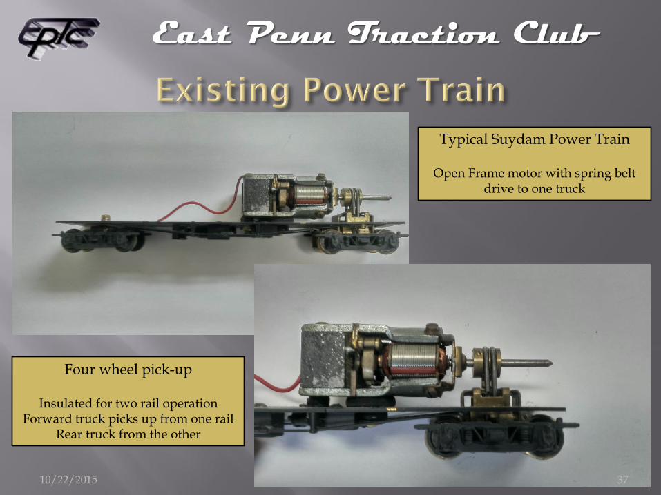
Typical Suydam Power Train
Open Frame motor with spring belt drive to one truck
Four wheel pick-up
Insulated for two rail operation Forward truck picks up from one rail
Rear truck from the other
10/22/2015 37

East Penn Traction Club
Motor Replace Open Frame
motor with can motor and flywheel assembly from North West Short Line (NWSL) Two varieties
1162-4 for “narrow” body
162-4 “wide” body Same motor, different
flywheel diameter
Bowser “improved” drive train is also a very smooth, reliable candidate
10/22/2015 38

East Penn Traction Club
Instructions
Motor & Flywheel Double Stick Foam
Coupling Components
Coupling Components
10/22/2015 39

East Penn Traction Club
NWSL 2032D-9 motor with flywheel 9500 RPM @ 12VDC
(dimensions as measured, not spec’d)
1.788” 45.43mm
0.706” 17.98mm
0.605” 15.35mm
0.799” 20.27mm Red dot
marks positive terminal
10/22/2015 40

East Penn Traction Club
Motor Replacement (Gear Tower) Most gear tower drives are connected to the motor
through a ball and socket universal
Remove Open Frame motor
Remove the socket from the Open Frame motor shaft Set screw
Open Frame Motor shaft is 2.4mm diameter
Can Motor shaft if 2.0mm diameter
Install brass sleeve on Can Motor shaft to increase diameter Secure with locktite
Install socket on Can Motor shaft
10/22/2015 41

East Penn Traction Club
Motor Replacement (Gear Tower) Position Can Motor and connect socket with ball
Test for minimum radius
Ball “spokes” should not bottom out in socket slots
Verify vertical/horizontal alignment of motor shaft and ball shaft Use shim if necessary
Use double stick tape/foam to temporarily mount motor and install body to insure no interference from the body roof/sides/trolley bases.
If OK attach Motor assembly to frame using DEVCON flexible adhesive and any shim required.
After 24 hour curing, finish attaching wires to motor.
10/22/2015 42

East Penn Traction Club
Motor Replacement (Spring Belt Drive) Most Spring Belt Drives are connected to the motor
through a pulley on the motor shaft
Note position and height of motor shaft prior to removal
Remove Open Frame motor
Remove the pulley from the Open Frame motor shaft Set screw
Open Frame Motor shaft is 2.4mm diameter
Can Motor shaft if 2.0mm diameter
Install brass sleeve on Can Motor shaft to increase diameter Secure with locktite
Install pulley on Can Motor shaft
10/22/2015 43

East Penn Traction Club
Measuring position of old motor and shaft height prior to removal. Shaft center line is 0.5” above car floor.
New shaft must be at the same height to assure proper spring belt tension.
10/22/2015 44

East Penn Traction Club
Motor removed. Spring belt pulley with set screw
Spring belt pulley installed on new motor shaft
Brass sleeves to increase new motor shaft diameter to fit spring belt pulley
Brass sleeve installed on new motor shaft
10/22/2015 45

East Penn Traction Club
Motor Replacement (Spring Belt Drive) Place Can Motor in position noted before Open Frame Motor
removal Attach belts to pulley
Turn flywheel and verify wheels turn and belts do not slip Verify vertical/horizontal alignment of motor shaft
Use shim if necessary Remove belts from motor shaft pulley Use double stick tape/foam to temporarily mount motor and
install body to insure no interference from the body roof/sides/trolley bases.
If OK attach Motor assembly to frame using DEVCON flexible adhesive and any shim required.
After 24 hour curing Attach spring belts to motor shaft pulley Finish attaching wires to motor.
10/22/2015 46

East Penn Traction Club
New motor with flywheel installed using silicone adhesive
10/22/2015 47

East Penn Traction Club
When running multiple trolleys with one throttle, it is desirable that all the trolleys operate roughly at the same speed for a given voltage.
If the speed of the finished trolley is too fast, diodes can be placed in series with the motor to provide a voltage drop to lower the speed of the trolley for a given throttle setting.
10/22/2015 48
East Penn Traction Club
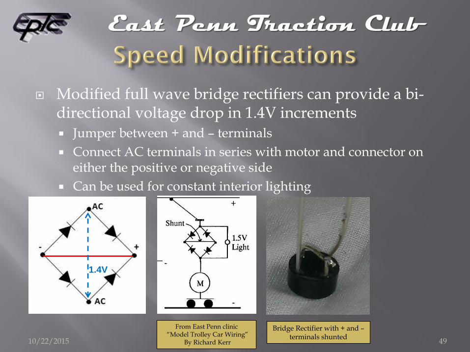
Modified full wave bridge rectifiers can provide a bi-directional voltage drop in 1.4V increments Jumper between + and – terminals
Connect AC terminals in series with motor and connector on either the positive or negative side
Can be used for constant interior lighting
1.4V
From East Penn clinic “Model Trolley Car Wiring”
By Richard Kerr
Bridge Rectifier with + and – terminals shunted
10/22/2015 49

East Penn Traction Club
Two bridge rectifiers installed on project trolley along with additional
weight over trailing truck 10/22/2015 50

East Penn Traction Club
10/22/2015 51

East Penn Traction Club
Suydam Sacramento Northern
Niles Coach
10/22/2015 52

East Penn Traction Club
NWSL Brill Master Unit
10/22/2015 53

East Penn Traction Club
Ken Kidder Double Truck Birney
10/22/2015 54

East Penn Traction Club
Fairfield Interurban
10/22/2015 55

East Penn Traction Club
Insulating Bushings: Customtraxx #SCTC-2 $ 1.25 (pr)
Brass Pivot: Customtraxx # SCTC-1 or Bowser #12508 $ 1.50 (pr)
Miniatronics Connector: #MNT5000301 $14.26 (ea)
Trolley Poles: Miniatures by Eric $29.95 (pr)
(including SCTC-1, SCTC-2) $32.00 (pr)
Bowser PCC (Form 11) Bowser #12600 $14.00 (ea) (includes brass pivot)
Brass Sleeves: Customtraxx #12053 $ 5.95 (4 pk)
Flywheel Cement Customtraxx #20010 $ 4.25 (ea)
Motor/Flywheel: NWSL #162-4 $52.95 (ea)
NWSL #1162-4 (narrow flywheel) $49.95 (ea)
10/22/2015 56

East Penn Traction Club
Bowser mechanisms Includes motor, power and $47.50 (ea)
trailing truck, mounts and couplings
26”, 28”, 30”, 33” wheels
No Flywheel
Flywheel retrofit Kit $ 8.50 (ea)
A-Line motors $47.00 (ea)
Flywheels $10.95 (2 pk)
Couplings $ 7.95 (ea)
10/22/2015 57

East Penn Traction Club
The author wishes to acknowledge inputs from the following sources: Trolleyville “Schoolhouse” Clinics
George Huckaby
East Penn Traction Club Clinics Bob Dietrich
Rich Kerr
Dave Gairo
Charles Long
Author email: [email protected]
10/22/2015 58