earth resistivity test report - amtz.in · pdf file2017 earth resistivity test report name of...
TRANSCRIPT
2017
EARTH RESISTIVITY TEST REPORT
NAME OF THE PROJECT: STUDIES WORK FOR ANDHAPRADESH MEDTECH ZONE
(AMTZ), VISHAKHAPATNAM, ANDHAPRADESH
LOCATION: ELECTRO MEGNETIC, ANDHAPRADESH
Report Ref. No: IDAX/REP/2017060007/FD‐ERT/2017‐18/423
TESTING AGENCY: IDAX CONSULTING & RESEARCH PVT.LTD.
Plot No. - 5016, Duplex-E, Brundaban Enclave, VSS Nagar,
Bhubaneswar-751007, Odisha (INDIA).
Tel: +91-674-3199991, 2360019, Fax: +91-674-2360019
E-mail: [email protected]
Web: www.idaxconsulting.com
Date of Test: 06.07.2017
Date of Submission of Report: 08.07.2017
IDAX CONSULTING & RESEARCH PVT.LTD.
Project Code‐ 2017060007_ERT Page 1 of 8
1. INTRODUCTION:
The Earth Resistivity Test (ERT) of soil was carried out at site for STUDIES WORK FOR
ANDHRAPRADESH MEDTECH ZONE (AMTZ), VISHAKHAPATNAM, ANDHRAPRADESH. with
the aim to determine an average value of electrical resistivity of soil for design of safe
earthing system. The Earth resistivity field test was done in 06/07/2017 at one location
given as directed by the client.
2. PURPOSE OF INVESTIGATION:
The purpose of this investigation is to determine an average value of electrical
resistivity of subsurface for design of safe earthing system with the help of
Microprocessor based electrical resistivity meter model DET-Auto.
3. GEOPHYSICAL INVESTIGATION:
Geophysical investigation was carried out as per IS: 3043-1987 on the basis of Earth
Resistivity meter model no. DET-Auto. Wenner’s four-electrode method is used to
determine the earth resistivity.
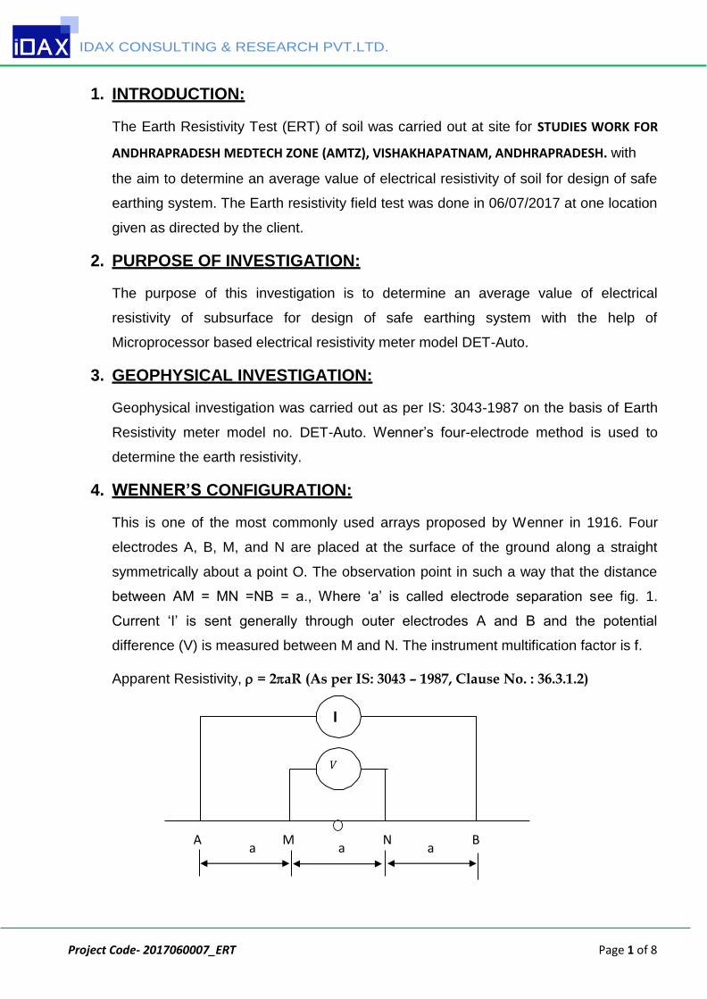
4. WENNER’S CONFIGURATION:
This is one of the most commonly used arrays proposed by Wenner in 1916. Four
electrodes A, B, M, and N are placed at the surface of the ground along a straight
symmetrically about a point O. The observation point in such a way that the distance
between AM = MN =NB = a., Where ‘a’ is called electrode separation see fig. 1.
Current ‘I’ is sent generally through outer electrodes A and B and the potential
difference (V) is measured between M and N. The instrument multification factor is f.
Apparent Resistivity, = 2aR (As per IS: 3043 – 1987, Clause No. : 36.3.1.2)
A a
M a
N a
B
I
V
IDAX CONSULTING & RESEARCH PVT.LTD.
Project Code‐ 2017060007_ERT Page 2 of 8
5. Survey Procedure:
Resistivity sounding is used to make investigations along the depth. In this method
the center of configuration is kept fixed and measurements are made by successively
increasing electrode spacing. The apparent resistivity values obtained with increasing
values of electrode separations are used to estimate the thickness and resistivity of
the subsurface formations. In Wenner’s configuration all the four electrodes are
arranged in a line at a equal distance ‘a’ between the consecutive electrodes.
Measurements were taken at 1m,2m,3m & 5.0m. Current is sent through the outer
electrodes and the potential difference is measured between the inner electrodes.
The Resistance (R = V/I) is measured for each electrode separation and apparent
resistivity is calculated by multiplying value of ‘R’ with Wenner configuration factor
(2a), where ‘a’ is the uniform distance between the elctrodes. The computation of
the sounding data is discussed in the subsequent section.
6. Computation of Earth Resistivity:
When the earth resistivity readings for different electrode spacing in a direction are
within 20 to 30%, the soil is considered to be uniform. When the spacing is increased
gradually from low values, at a stage, it may be found that the resistivity readings are
more or less constant irrespective of the increase in the electrode spacing. The
resistivity for this spacing is noted and taken as the resistivity for that direction. In a
similar manner, resistivity for at least one equally spaced direction from the center of
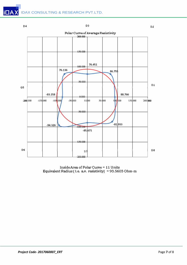
the site are measured. These resistivity are plotted in a graph sheet in the appropriate
directions choosing a scale. A closed curve is plotted on the graph sheets jointing all
the resistivity points plotted to get the polar resistivity curve. The area inside the polar
resistivity curve is measured and equivalent circle of the same area is found out. The
radius of this equivalent circle is the average resistivity of the site under consideration.
The average resistivity thus obtained may be used for the design of the earthing grid
at that particular depth.
IDAX CONSULTING & RESEARCH PVT.LTD.
Project Code‐ 2017060007_ERT Page 3 of 8
7. Results:
I. The electric resistivity test of the site were performed in 06/07/2017 at one location as
suggested by client.
II. Measured surface resistivity data is attached separately.
III. Average Resistivity / Equivalent Radius from polar curve is 93.560 ohm-m.
8. LIMITATION
The Electrical resistivity testing has been carried out at the location chosen by the
client. In general resistivity values are influenced by water, presence of dissolved ions
in soil media and nature of strata. Recommendations made in the report are hence
valid only for tested locations only. However if there is any change in subsoil
conditions and properties at places beyond chosen test locations, the soil consultants
to be contacted for further guidance.
For IDAX CONSULTING & RESEARCH PVT.LTD.
Engineer – Civil (Soil) Er. Pratiksha Ray B. Tech- Civil
(Head - Civil)
Er. Deepak Kumar Mallick
B. Tech (Hons.) – Civil (IIT Kharagpur)
IDAX CONSULTING & RESEARCH PVT.LTD.
Project Code‐ 2017060007_ERT Page 4 of 8
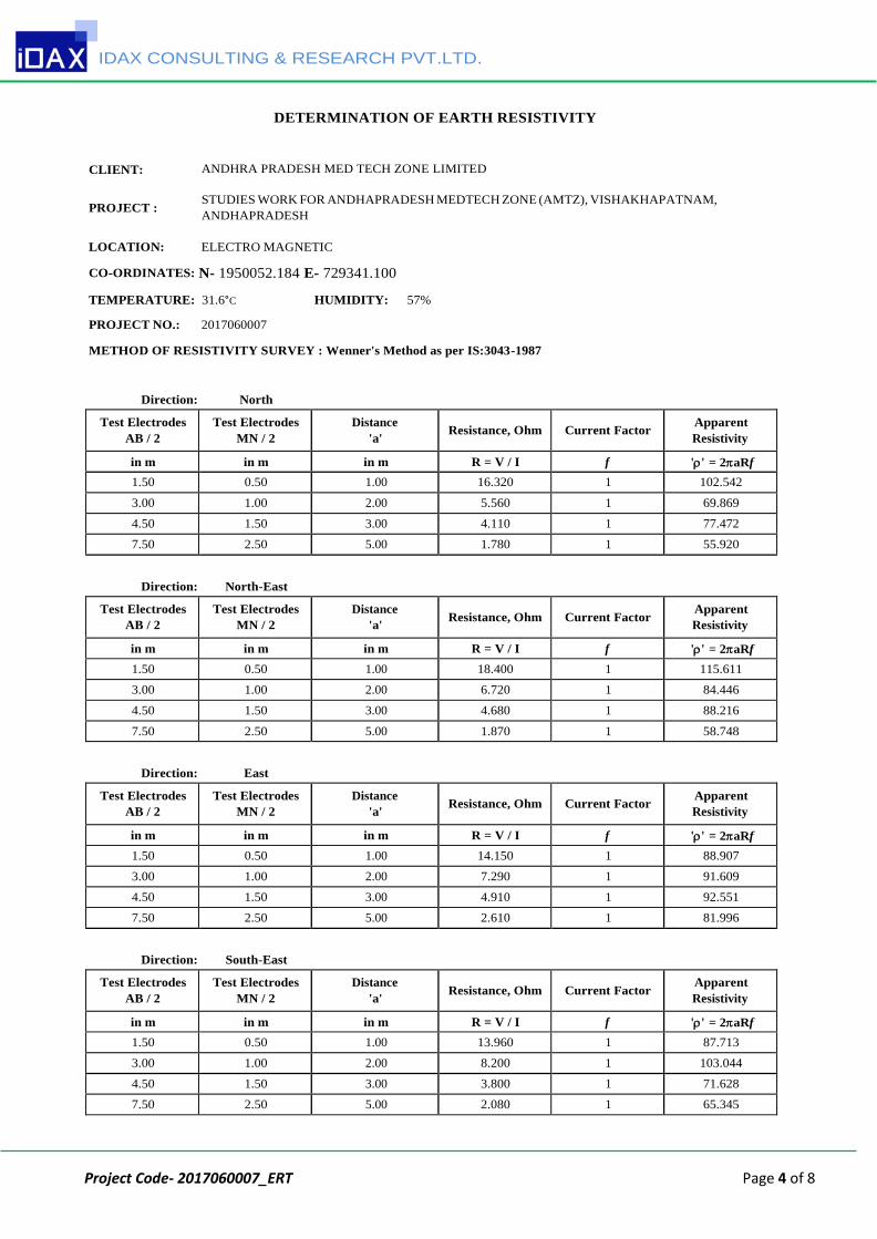
DETERMINATION OF EARTH RESISTIVITY
CLIENT:
PROJECT :
ANDHRA PRADESH MED TECH ZONE LIMITED
STUDIES WORK FOR ANDHAPRADESH MEDTECH ZONE (AMTZ), VISHAKHAPATNAM,
ANDHAPRADESH
LOCATION: ELECTRO MAGNETIC
CO-ORDINATES: N- 1950052.184 E- 729341.100
TEMPERATURE: 31.6°C HUMIDITY: 57%
PROJECT NO.: 2017060007
METHOD OF RESISTIVITY SURVEY : Wenner's Method as per IS:3043-1987
Direction: North
Test Electrodes
AB / 2
Test Electrodes
MN / 2
Distance
'a'
Resistance, Ohm
Current Factor Apparent
Resistivity
in m in m in m R = V / I f '' = 2aRf
1.50 0.50 1.00 16.320 1 102.542
3.00 1.00 2.00 5.560 1 69.869
4.50 1.50 3.00 4.110 1 77.472
7.50 2.50 5.00 1.780 1 55.920
Direction: North-East
Test Electrodes
AB / 2
Test Electrodes
MN / 2
Distance
'a'
Resistance, Ohm
Current Factor Apparent
Resistivity
in m in m in m R = V / I f '' = 2aRf
1.50 0.50 1.00 18.400 1 115.611
3.00 1.00 2.00 6.720 1 84.446
4.50 1.50 3.00 4.680 1 88.216
7.50 2.50 5.00 1.870 1 58.748
Direction: East
Test Electrodes
AB / 2
Test Electrodes
MN / 2
Distance
'a'
Resistance, Ohm
Current Factor Apparent
Resistivity
in m in m in m R = V / I f '' = 2aRf
1.50 0.50 1.00 14.150 1 88.907
3.00 1.00 2.00 7.290 1 91.609
4.50 1.50 3.00 4.910 1 92.551
7.50 2.50 5.00 2.610 1 81.996
Direction: South-East
Test Electrodes
AB / 2
Test Electrodes
MN / 2
Distance
'a'
Resistance, Ohm
Current Factor Apparent
Resistivity
in m in m in m R = V / I f '' = 2aRf
1.50 0.50 1.00 13.960 1 87.713
3.00 1.00 2.00 8.200 1 103.044
4.50 1.50 3.00 3.800 1 71.628
7.50 2.50 5.00 2.080 1 65.345
IDAX CONSULTING & RESEARCH PVT.LTD.
Project Code‐ 2017060007_ERT Page 5 of 8
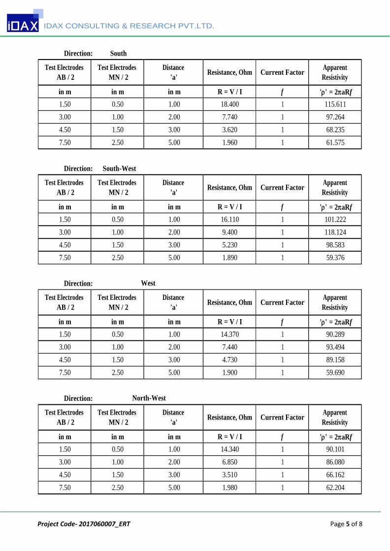
Direction: South
Test Electrodes
AB / 2
Test Electrodes
MN / 2
Distance
'a' Resistance, Ohm Current Factor
Apparent
Resistivity
in m in m in m R = V / I f '' = 2aRf
1.50 0.50 1.00 18.400 1 115.611
3.00 1.00 2.00 7.740 1 97.264
4.50 1.50 3.00 3.620 1 68.235
7.50 2.50 5.00 1.960 1 61.575
Direction: South-West
Test Electrodes
AB / 2
Test Electrodes
MN / 2
Distance
'a' Resistance, Ohm Current Factor
Apparent
Resistivity
in m in m in m R = V / I f '' = 2aRf
1.50 0.50 1.00 16.110 1 101.222
3.00 1.00 2.00 9.400 1 118.124
4.50 1.50 3.00 5.230 1 98.583
7.50 2.50 5.00 1.890 1 59.376
Direction: West
Test Electrodes
AB / 2
Test Electrodes
MN / 2
Distance
'a' Resistance, Ohm Current Factor
Apparent
Resistivity
in m in m in m R = V / I f '' = 2aRf
1.50 0.50 1.00 14.370 1 90.289
3.00 1.00 2.00 7.440 1 93.494
4.50 1.50 3.00 4.730 1 89.158
7.50 2.50 5.00 1.900 1 59.690
Direction: North-West
Test Electrodes
AB / 2
Test Electrodes
MN / 2
Distance
'a' Resistance, Ohm Current Factor
Apparent
Resistivity
in m in m in m R = V / I f '' = 2aRf
1.50 0.50 1.00 14.340 1 90.101
3.00 1.00 2.00 6.850 1 86.080
4.50 1.50 3.00 3.510 1 66.162
7.50 2.50 5.00 1.980 1 62.204
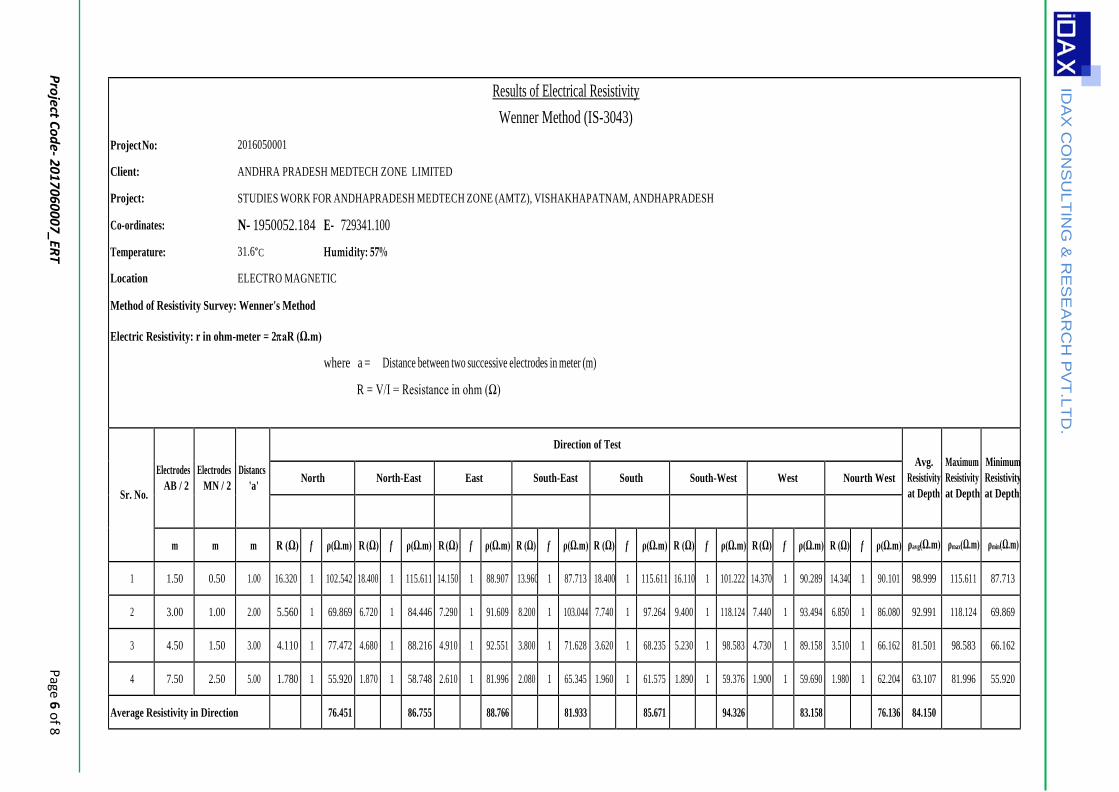
Results of Electrical Resistivity
Wenner Method (IS-3043)
Project No: 2016050001
Client: ANDHRA PRADESH MEDTECH ZONE LIMITED
Project: STUDIES WORK FOR ANDHAPRADESH MEDTECH ZONE (AMTZ), VISHAKHAPATNAM, ANDHAPRADESH
Co-ordinates: N- 1950052.184 E- 729341.100
Temperature: 31.6°C Humidity: 57%
Location ELECTRO MAGNETIC
Method of Resistivity Survey: Wenner's Method
Electric Resistivity: r in ohm-meter = 2aR (Ω.m)
where a = Distance between two successive electrodes in meter (m)
R = V/I = Resistance in ohm (Ω)
Sr. No.
Electrodes
AB / 2
Electrodes
MN / 2
Distancs
'a'
Direction of Test
Avg.
Resistivity
at Depth
Maximum
Resistivity
at Depth
Minimum
Resistivity
at Depth
North North-East East South-East South South-West West Nourth West
m m m R (Ω) f ρ(Ω.m) R (Ω) f ρ(Ω.m) R (Ω) f ρ(Ω.m) R (Ω) f ρ(Ω.m) R (Ω) f ρ(Ω.m) R (Ω) f ρ(Ω.m) R (Ω) f ρ(Ω.m) R (Ω) f ρ(Ω.m) ρavg(Ω.m) ρmax(Ω.m) ρmin(Ω.m)
1 1.50 0.50 1.00 16.320 1 102.542 18.400 1 115.611 14.150 1 88.907 13.960 1 87.713 18.400 1 115.611 16.110 1 101.222 14.370 1 90.289 14.340 1 90.101 98.999 115.611 87.713
2 3.00 1.00 2.00 5.560 1 69.869 6.720 1 84.446 7.290 1 91.609 8.200 1 103.044 7.740 1 97.264 9.400 1 118.124 7.440 1 93.494 6.850 1 86.080 92.991 118.124 69.869
3 4.50 1.50 3.00 4.110 1 77.472 4.680 1 88.216 4.910 1 92.551 3.800 1 71.628 3.620 1 68.235 5.230 1 98.583 4.730 1 89.158 3.510 1 66.162 81.501 98.583 66.162
4 7.50 2.50 5.00 1.780 1 55.920 1.870 1 58.748 2.610 1 81.996 2.080 1 65.345 1.960 1 61.575 1.890 1 59.376 1.900 1 59.690 1.980 1 62.204 63.107 81.996 55.920
Average Resistivity in Direction
76.451
86.755
88.766
81.933
85.671
94.326
83.158
76.136 84.150
IDA
X C
ON
SU
LT
ING
& R
ES
EA
RC
H P
VT
.LT
D.
Pro
ject Co
de‐ 2
01
70
60
00
7_ER
T
Page 6
of 8
IDAX CONSULTING & RESEARCH PVT.LTD.
Project Code‐ 2017060007_ERT Page 7 of 8

IDAX CONSULTING & RESEARCH PVT.LTD.
Project Code‐ 2017060007_ERT Page 8 of 8