early-stage assessment of the impacts of next generation...
TRANSCRIPT
1
Dr. Douglas T. Rigterink*1, Robert Ames
2, Dr. Alexander Gray
1, Dr. Norbert Doerry
3
1Naval Surface Warfare Center-Carderock Division, Future Ship and Submarine Concepts Branch
2Office of Naval Research
3Naval Sea Systems Command SEA05T
Early-Stage Assessment of the Impacts of Next Generation
Combat Power and Energy Systems on Navy Ships
ABSTRACT The newest suite of weapon and C4I systems for
the next generation of Navy ships will have
electrical power requirements far greater than
any current design. As of today, the Navy does
not have processes or the tools for addressing
the coupled problems of high power electrical
system design, control, and vulnerability
analysis. The task of formalizing a process and
developing requirements for these necessary
tools has been assumed by the Design Tools and
Methodology Working Integrated Product Team
(DTM WIPT) as part of the Navy’s Combat
Power and Energy Systems Overarching
Integrated Product Team.
This paper presents one of the processes
developed by the DTM WIPT which utilizes the
concept of ship distribution systems “patterns
and templates” combined with a process for
design space exploration of ship platforms. The
use of system patterns and templates is enabled
by the newly developed Smart Ship Systems
Design (S3D) tool, and design space exploration
is facilitated by the Rapid Ship Design
Environment (RSDE), the Advanced Ship and
Submarine Evaluation Tool (ASSET), and the
Leading Edge Architecture for Prototyping
Systems (LEAPS). The envisioned process will
be described in detail and anticipated impacts of
the process will be presented. The paper
concludes with a description of the near- and
long-terms plans for the Navy’s suite of design
tools in regards to novel distributed system
architectures.
*Corresponding Author. Please contact at
INTRODUCTION We are entering an age where power and energy
requirements will fundamentally change the way
we design and engineer ships. This is being
driven by systems with high power electrical
components like lasers and railguns. Ships
cannot support these high energy systems with
very large pulse loads without modifications to
the ship’s electric power plant, energy storage,
and other complementary and supporting ship
systems.
Within the next four years, a new high energy
system will come online every two years. These
systems will rely on common enabling
technologies like next generation power
converters and energy storage devices. The
Navy has realized that streamlining integration
efforts of these common systems is paramount to
success. Without a focused effort to develop a
common integration approach, the developer of
each system will be required to develop his or
her own integration solution – with adverse size,
weight, cost, complexity, and maintenance
impacts. To this end, the Combat Power and
Energy Systems Overarching Integrated Product
Team (CPES OIPT), under the leadership of
PEO SHIPS and NAVSEA 05, was formed.
The CPES OIT has two major functions. For
Today’s Navy and Tomorrow’s Navy, it will
provide a path to ship integration for high power
and energy weapons and sensors for both
existing and future ships by coordinating efforts
and resource. For the Navy After Next, it will
provide a path for identification, development,
and demonstration of technologies leading to a
fully integrated power and energy system.
2
The CPES OIPT found that a lack of
coordination between the different high energy
system design groups lead to:
Stove piped approaches producing only point
solutions
Redundant approaches on the same platform
Unnecessarily complex system integration
Overstretched technical resources
Increased acquisition and support costs
The goal is to move towards a more coordinated
effort with an integrated approach for high
energy systems design that identifies overlaps
and gaps in development efforts and seeks to
find the most affordable, common solutions. The
CPES OIPT is the first step towards this goal.
By bringing together a diverse spectrum of
organizations within the modernization, new
construction, resource sponsor, and research and
development communities, the CPES OIPT
allows these disparate groups to share lessons
learned, leverage investments, seek common
solutions for similar issues, and coordinate
schedules and budgets.
The CPES OIPT was broken into six smaller
Working Integrated Product Types (WIPTS):
Business Operations and Costing, Power
Systems and Technical Architecture,
Requirements and CONOPS, Mission System
and Characterization, Ship Systems Engineering
and Platform Integration, and Design Tools and
Methodology (DTM). The remainder of this
paper will focus on the DTM WIPT.
The DTM WIPT was created to coordinate with
the Office of Naval Research, NAVSEA 05D,
NAVSEA 05T, and PMS 320 to develop, plan,
and highlight the funding requirements for
updating the Navy’s design tools to
accommodate advanced power and energy
analyses. The DTM WIPT was also tasked to
indentify other tools and design approaches that
may be required to integrate these analyses into
the Navy’s design process.
The requirements for high energy pulse load
mission systems will require new design
methodologies and modeling and simulation
(M&S) tools. These M&S tools must support
concept design for both platform and system
architecture studies. Preliminary design studies
will require real time electric and control system
M&S capabilities including power mission
systems and hardware in the loop options for
critical capabilities for all platform variants.
Many of these tools do not exist.
This paper will detail some of the M&S findings
of the DTM WIPT within the concept and early
preliminary design phases with respect to ship
design and power and energy system
architecture. Namely, it will introduce the
“Pattern and Template” approach for designing
and determining the representative costs for
advanced power systems. Next, the paper will
detail the capabilities of a number of the Navy’s
design tools (LEAPS, S3D, ASSET, and RSDE).
The paper will then propose a methodology for
combining the pattern and template distributed
systems design approach with the Navy’s design
tools that allows for both point-based and set-
based design.
SHIP SYSTEM PATTERNS A ship system pattern is a non-ship specific
instantiation of a ship system technical
architecture (Medium Voltage DC, Medium
Voltage AC, etc.). Figure 1 shows an example of
a six zone, ring bus, Medium Voltage DC power
distribution system pattern. In this section the
focus is on electrical systems, but the pattern
concept applies to any distributed system
discipline.
At the highest level a system pattern is defined
by the technical architecture requirements it is
derived from and its number of system zones,
which are typically related to the number of ship
subdivision zones. Each system pattern is
intended to provide system topology, provide
component placement information at the zone
level, and associate the system with a technical
architecture. The associated technical
architecture will provide the design practices
and criteria, specifications, and standards based
on the type of power system.

3
The bus voltage and bus type (cable, bus duct,
etc.) should be common between all zones. In
accordance with best practices, all auxiliary
generators, main generators, shore power
conversion modules, and propulsion motor
modules should be common across all zones.
Auxiliary propulsion modules are not required to
be common, depending on their application.
Each electrical zone can be unique in its number
of auxiliary generators, main generators, shore
power conversion modules, propulsion motor
modules, and large or pulse electronic loads.
System patterns can either be fixed, where the
number of components is not adjustable, or
flexible where the number of components is
adjustable.
Each pattern will include the types of equipment
in each electric zone, but will not specify the
model of that component, i.e., Zone 4 has two
gas turbines vice Zone 4 has two Rolls Royce
MT30s.
The intermediate step of creating patterns before
sizing any components is necessary because
design practices and criteria are not defined for
new technical architectures like Medium
Voltage DC systems. It is necessary to have a
model that can cope with significant uncertainty
until rules are created. For more established
technical architectures like MVAC systems,
current modeling capabilities do not account for
energy storage or pulse loads. Modeling
capabilities are also lacking for zonal designs,
control system properties, high power loads, and
propulsion options.
The Patterns Approach is intended to be used in
the pre-study phase of an acquisition program.
These pre-studies serve to narrow the options
considered in concept exploration by providing
insight about which design options are unlikely
to be viable solutions.
By removing these dominated solutions before
any component sizing has occurred, the entire
concept exploration phase can be accelerated as
Figure 1: A six electric zone Medium Voltage DC System Architecture Pattern. Notice no specific equipment models have been called out, only the type of equipment required in
each electric zone.
4
it can be focused on just those options which are
likely to succeed. Additionally, these pre-studies
can inform behavior models and be used to
develop synthesis algorithms for sizing those
options which are feasible.
Using the patterns requires a way to create 2D
system schematics that can be analyzed to make
sure all the requisite components are present and
properly connected. To transition the patterns to
templates one must prescribe values to the
previously notional system components and
analyze the feasibility of the system. To do an
actual concept study that template then needs to
be transitioned into a ship design and holistically
analyzed to determine the whole ship impacts
and feasibility. And for any part of this process
to be adopted, this all must easily and quickly
achieved
The next section of this paper will discuss how
four Navy developed design and analysis tools
can be used exactly for this purpose.
S3D The Smart Ship Systems Design (S3D) tool is
one of the products created by the ONR funded
Electric Ship Research and Design Consortium
(ESRDC). The ESRDC was tasked to research
and subsequently develop a collaborative,
concurrent, web-based environment for the
design of Navy ships, which became S3D
(Andrus, et al., 2013).
Though S3D was originally developed as a web-
based tool, the realities of the Navy’s design
process and the desire to integrate S3D with
Navy’s suite of design tools (the LEAPS
software environment) and security
requirements made it necessary to develop a
standalone desktop version of the tool (Chalfant,
Ferrante, & Noble, 2014; Chalfant, Ferrante,
Chryssostomidis, & Langland, 2015). While
converting to a standalone tool made the
collaboration features of S3D superfluous,
migrating from an SQL Server for persisting
design information to a LEAPS database format
allowed for the sharing of design information
between LEAPS applications, especially S3D,
ASSET, and RSDE.
Additionally, S3D requirements helped to
formalize the definitions of ship systems within
the LEAPS ship product model, known as the
Formal Object Classification for Understanding
Ships (FOCUS). Formalizing the system
definition allows the user to quickly define and
connect systems and assists the creation of
models for higher fidelity deactivation and
survivability analysis (Dellsy, Parker, &
Rigterink, 2015).
S3D is comprised of a number of tools that
support various engineering disciplines with the
design and analysis of electrical systems,
mechanical systems, and air and liquid cooling
systems, as well as the arrangement of
equipment in 3D space from the naval
architect’s perspective (Chalfant, Langland, et
al., 2015).
S3D can be used to implement the ship system
patterns approach in a four step process. First the
necessary components (both notional and actual)
and their associated solvers would need to be
created. Next, systems patterns containing
notional components with logical connections
are made. These patterns are then populated with
additional component and connection data to
create a system template. This includes replacing
the notional components with their real world
counterparts, if they are available. If the design
requires a component with attributes not yet
available then it will be left as a notional
component. The template is then simulated to
test feasibility and corrections are made until a
feasible system is created. Finally, the user can
attempt to place the system within a ship model
and again can test the system for feasibility, this
time including additional losses due to cable
lengths and piping runs. The remainder of this
section will cover, in more detail, the
aforementioned four phases.
Component Creation
A user would first create the components
(generators, gas-turbines, etc.) necessary for
modeling the candidate systems. To fully model
a component the user must assign a weight, an
area and volume requirement, and model the
component's electrical, mechanical, and thermal
5
behaviors. Fuel requirements for engines must
also be defined.
The user is provided with a number of
simulation models for common components like
electric motors or gas turbines. These
computational solvers characterize the behavior
of a component during simulation. Component
attributes or properties are used to provide static
properties like weight or simulation parameters
for each component. These provided
components come in two types. The first type is
notional components where the user is free to
modify the component values, for example
creating a hypothetical gas turbine that produces
25,000kW but only weighs 10t. The second
type, actual components, represent real products
like a GE LM2500 which has locked
output production of 24,050kW and a weight of
90t, per manufacturer’s specifications.
For next generation components, like Power
Electronic Building Blocks, where a simulation
model is not already available in S3D, the user
would need to code that component’s simulation
model(s), associate the model with the
component, and place it in a LEAPS catalog for
use by S3D.
Pattern and Template Creation
To create a system pattern and then a template,
the components must first be connected together
logically in a schematic view, similar to what
has been shown in Figure 1. S3D can be used to
create this logical connection in the electrical,
mechanical, and thermal fluid domains.
During the pattern creation process, the
components are connected using logical
connectors rather than specifying wires, cables,
shafts, or pipes. Additionally, a majority of the
components will not be defined beyond their
name and basic properties. Even at this limited
level of fidelity, the system pattern can be tested
for consistency of things like electrical power
type (AC vs. DC) or fluid flow direction.
Once a pattern has been defined with all
connections and component placeholders, the
user will adapt it to his or her design by
replacing the notional components with actual
components, to the extent possible. It is highly
likely that S3D will be used for future concept
studies where there is no actual component that
will meet certain requirements, so a notional
component will need to be used. At this time, the
user would be required to enter all component
properties, but in the near future a property
estimation tool will be available, thereby
allowing the user to specify a few critical
properties and then let the tool fill in the
remaining properties.
During the template creation process, the user
can intermittently simulate the systems at
whatever levels of detail are available and adjust
properties accordingly. For example, the
electrical simulation can be run once all the
components are placed, but without calling out
the cable properties. If a load is not receiving
sufficient power before the cables are included
then the user will know that the generating
capabilities need to be increased.
The goal is to create a large number of agreed
upon patterns that can be distributed with the
S3D software so that the designers can for the
most part skip the pattern creation step and
immediately begin the component assignment
process necessary to convert a pattern to a
template. It may even be possible to distribute a
number of templates so that users can move
directly to the component placement process.
Component Placement
Once a template has been created, it is necessary
to simulate it to prove that the right components
and connections exist in the system, and the
system is feasible in a schematic context. While
physically arranging components in the 3D
naval architecture view is not required for
simulation, it is incomplete without it. Creating
the physical connections allows S3D to analyze
the effects of things like cable length on
impedance and calculate the length of the
propeller shafts. Placing the components also
arranges and associates structural subdivision
zones with electrical or other system zones.
6
The arrangement and placement of components
in a ship requires the existence of a LEAPS ship
concept. While any tool can populate a concept
to a LEAPS database, but in general, S3D
assumes that the concept was populated by
ASSET, and therefore includes structural
subdivisions, deckhouse, propellers, and prime
movers. The structural zones, as generated by
ASSET, will provide arrangement boundaries
for S3D.
Once all components are placed, the user can run
an electrical, mechanical, or thermal fluids load-
flow simulation to determine if all the
components are receiving their required power
and cooling. Additionally, the user can run the
simulation for a specific discipline at any time
during the process of creating the system
architecture model. A system architecture, as
defined within this process, is the 3D
arrangement of all components and the
subsequent refinement of component properties
needed for successful simulation.
At this time S3D only performs a steady state
analysis, intended for early-stage conceptual
design. This is consistent with other early-state
system design practices. The possibility of
adding dynamic, time domain analysis and
controls systems simulations is currently being
explored.
Once a system architecture has been created in
S3D it is necessary to assess its impact on the
ship platform for which it is designed. Thanks to
LEAPS integration, a system model (whether or
not it is created around a specific ship) can be
easily imported into an existing LEAPS ship
concept and the impacts can be analyzed via
ASSET or any of the other LEAPS tools.
LEAPS The Leading Edge Architecture for Prototyping
Systems (LEAPS) is a development framework
that supports virtual prototyping and analysis of
conceptual and preliminary ship designs through
integration of many design and modeling and
simulation tools. The LEAPS Application
Programming Interface (API) contains a set of
generic data classes that describe physical and/or
functional representations of engineered
products.
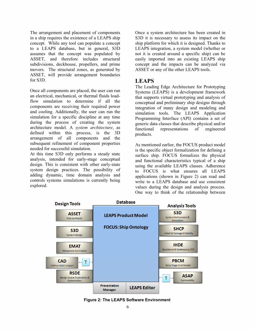
As mentioned earlier, the FOCUS product model
is the specific object formalization for defining a
surface ship. FOCUS formalizes the physical
and functional characteristics typical of a ship
using the available LEAPS classes. Adherence
to FOCUS is what ensures all LEAPS
applications (shown in Figure 2) can read and
write to a LEAPS database and use consistent
values during the design and analysis process.
One way to think of the relationship between
Figure 2: The LEAPS Software Environment

7
LEAPS classes and FOCUS objects
formalization is to draw a parallel between the
alphabet (classes) and English (formalization).
LEAPS also has formalized object ontologies for
air vehicles (AIRSOM) and submarines
(SUBSET).
LEAPS applications are typically divided into
two groups: design tools and analysis tools, as
shown in Figure 2. While the design tools
contain both modeling and analysis they provide
the bulk of the data used to populate a ship
concept into the LEAPS database. Analysis tools
are used to simulate and record the behaviour
associated with those representations. The tools
are represented here for convenience left to right
because analysis ususally depends on data
created by the design tools. No directionality is
implied and no tool communicates to any other
tool except through LEAPS data.
The three LEAPS tools that are the focus of this
paper are the aforementioned Smart Ship
Systems Design (S3D) tool, the Advanced Ship
and Submarine Evaluation Tool (ASSET), and
the Rapid Ship Design Environment (RSDE).
RSDE and ASSET are considered Design Tools
while S3D has both a design and analysis
component.
ASSET The Advanced Ship and Submarine Evaluation
Tool (ASSET) is the Navy’s concept design ship
synthesis tool. At the time of writing, ASSET is
undergoing a major change in philosophy and
work flow. In previous versions of ASSET (up
to and including version 6.3) the user entered a
set of ship design parameters and then ran a
synthesis algorithm which modified the design
until a converged ship was produced. This point-
based design process is depicted in the upper
portion of Figure 3.
The criteria for convergence were a basic
stability check based on the GMT to beam ratio,
a buoyancy check, and the numerical stability of
hundreds of other ship parameters, i.e., over two
successive iterations of the synthesis process all
calculated ship parameters did not vary by more
than a set, infinitesimally small amount. By and
large users were leery of the synthesis process
and complained about ASSET changing
parameters of the ship that they did not wish to
be changed.
In response to this feedback, future versions of
ASSET (version 7.0 and on) will not have a
strong emphasis on automated synthesis. Now,
users will be able to change the parameters of
the design they wish to be changed and then
evaluate what effects that change had on the
design. This “User in the Loop” process is
depicted in the lower portion of Figure 3.
The users will be aided by a series of “Design
Processes” which will assist in modifying the
design to meet a number of commonplace naval
architecture requirements, namely:
Area Balance - a process to make the design’s
deck area equal to that required by the mission
and support systems.
Speed-Power Balance - a process to select the
appropriate engines or modify the hullform
such that the ship meets a user set speed
requirement.
Design Waterline - Load Waterline Balance -
a process to make the full load waterline equal
to the original user specified hull design
waterline.
Range Balance - a process to ensure a design
meets its required range by modifying tankage
and hullform.
Stability Balance - a process to ensure a
design meets it stability requirements by
modifying hullform and load placement.
In addition to deemphasizing automated ship
synthesis, ASSET 7.0 and beyond will natively
store all design information in a FOCUS model
as part of a LEAPS database so that all other
tools within the LEAPS environment can access
that information. Previously, ASSET models
needed to undergo a conversion process to make
them FOCUS compliant. This conversion was
often unstable and time consuming, and any
changes made to the ship’s model outside of
ASSET would not be reflected in the ASSET
model.

8
Figure 3: A comparison of the ASSET 6.3 and ASSET 7.0 design processes.
The use of the LEAPS database for storing the
ASSET model also means the ship’s hull and
structural geometry are now saved as Non-
Uniform Rational B-Spline (NURBS) surfaces
(a standard way of representing 3D geometry in
CAD programs) instead of as a series of offsets
and stations. This means the ships 3D geometry
is captured at all times, which will simplify the
transition from an ASSET model to CFD or
FEA tool.
At least initially, the next generation of ASSET
will be a much more user intensive process, but
it will allow the users much more flexibility and
control over which ship parameters are being
modified. This additional control is the lynch-
pin of the integration of ASSET with S3D.
RSDE The Rapid Ship Design Environment (RSDE) is
a computational tool that allows users to harness
the capabilities of ASSET and other LEAPS
applications to perform Design Space
Exploration (DSE). RSDE facilitates DSE
through the use of Design of Experiments
(DoE). DoE is the formal strategy of developing
a collection of experiments in which a set of
design variables are varied in a systematic
manner. The purpose of which is to predict, and
discover, the relationships between design
variables and responses.
The current version of RSDE (version 1.2) uses
ASSET 6.3 as its ship synthesis engine. Future
versions of RSDE (version 2.0 and beyond) will
use ASSET version 7.0 for ship synthesis and
incorporate other LEAPS applications for
additional analysis.
A typical RSDE workflow is shown in Figure 4.
The process begins with a user creating a
baseline ship design in ASSET and selecting
which design variables he or she would like to
vary. For continuous variables (e.g., length,
beam, and endurance speed) the user selects the
range that the inputs will be varied over. For
discrete variables (e.g., specific engine models,
stiffener sizes, and plate thicknesses) the user
selects a set of potential alternatives to the
baseline variable.
From there the user chooses the number of
designs he or she would like RSDE to create and
then populates the design space either with user
specified design points (where the user chooses
the values of all the variables) or via a Latin
hypercube sampling method. RSDE then
synthesizes the desired number of designs and
runs each design through the requested analyses
and stores all the data in a LEAPS database.

9
Once the set of points is created it is the task of
the user to create behavior models to explore
relationships between inputs and outputs and
produce the visualizations necessary for
conveying the information to decision makers.
Figure 4: The typical RSDE workflow.
At this point, the user also has the option of
refining, or adding more information or fidelity,
to a chosen subset of designs from the initial
design space in an attempt to gain more
knowledge about the interdependencies between
the input and output variables. Design
refinement can be done in S3D or ASSET and
the remainder of the suite of LEAPS
applications can be used to produce higher
fidelity analysis information about the chosen
design.
PROPOSED DESIGN PROCESS The process detailed in this section is based
on the pattern and template approach introduced
early in this paper. The process leverages the
power of S3D and ASSET to quickly create an
initial point design (Chalfant, Ferrante, &
Chryssostomidis, 2015) and then shows how
S3D and RSDE can be used in tandem to
explore the design space around that initial
point. The process is an extension of previous
RSDE ship design processes (Mackenna, 2015).
To begin, a mixed team of systems designers
and naval architectures will need to create an
initial ASSET ship design and an initial system
pattern and template. The design created by
ASSET will not have the correct weights, areas,
or power levels for its machinery systems due to
the legacy sizing algorithms currently available
in ASSET. This model will serve only to give
the team a hull with known resistance
characteristics and structural weights. Using
S3D and the ship’s characteristics generated by
ASSET, the team will create an initial system
design that can then be fed back into the ASSET
model and used to rebalance the ship.
This process will be iterative, as major changes
in machinery sizing will lead to large changes in
the ship characteristics which will necessitate
machinery modifications, and so forth.
Eventually, the team will settle on a balanced
system and ship design. This balanced design is
the baseline for the remained of the process.
Once the baseline is agreed upon, the design
process begins to resemble a set-based design
process. The team could conceivably be split
into the systems group and the naval architecture
group, and the two groups could proceed
independently. The naval architecture group
would use the baseline to populate the design
space in RSDE. The design space could be
defined by variables pertaining to the systems
onboard the ship, achieved by assigning ranges
to the space, weight, area, power, and cooling
requirements of distribution system SWBS
groups. Alternatively, the ships principal
dimensions could be varied. A combination of
the two is also possible and RSDE allows the

10
users the ability to create equations to make one
variable the function of another.
Multiple system templates should be created so a
family of related design sets can be populated so
the systems team can fully explore the systems
design space. Each set would contain different
power capacities and topologies as provided by
their respective baseline. This will provide the
user with enough design variability across the
family of sets to properly inform decision
makers about the consequences of different
design decisions. Essentially, the systems group
will be manually populating the system design
space.
Once both groups are satisfied they have
sufficiently sampled their respective design
spaces, they will come back together and
investigate overlapping solutions (Figure 5).
From here, an additional set of criteria can be
applied to the design space, and the dominated
regions can be removed. The goal is to have a
smaller design space that is still feasible in both
the naval architecture and systems designs
spaces (Figure 6). From here, more detail can be
put into a new refined baseline using ASSET or
other LEAPS tools and a more detailed system
template can be created and the process can be
repeated. If a sufficient level of detail has been
reached, the team may either down select to a
single design or, keeping with the set-based
design philosophy, capture their findings about
the best region of the design space for meeting
certain requirements.
It is possible that many of the system templates
and many of the ship designs will no longer be
included in the non-dominated design space.
This should not be seen as a waste. Having
studied these dominated areas adds to the
Navy’s institutional knowledge, as new system
patterns and templates have been created which
may be useful for future studies. More
importantly, if the design requirements change
in the future, as they are want to do, an entire
new analysis will not be necessary; the design
team can fall back on the designs they created in
an earlier iteration of the exercise (Arcano,
2015; Ferrante, et. al., 2015).
Figure 5: The initial overlapped system and ship design variable design space without
outside constraints enforced.
Figure 6: The initially populated system and
ship design space showing both feasible and infeasible regions, dependent on additional
design constraints.
CONCLUSION In this paper, the System Pattern and Template
approach for designing advanced power systems
has been introduced along with a suite of tools
that can be used to facilitate the approach. The
process for enacting the pattern using S3D,
ASSET, and RSDE has been proposed.
In the short term, the various component and
system models within S3D will be verified and
validated by Navy. The process put forth in this
paper will be tested on a yet to be decided
design study. Additional features, like a mission
analysis tool, will be added to S3D within the
next calendar year.

11
In the long term additional capabilities will be
added to all the tools, potentially including a
controls system design feature for S3D. The
integration between RSDE and S3D will also be
strengthened with the goal of using RSDE to
vary machinery components directly in S3D and
then use those findings in conjunction with
ASSET models. In general the authors are
confident that the use of S3D in conjunction
with ASSET and RSDE will allow Navy
designers to more efficiently and accurately
design and analyze the next generation of
combat power and energy systems.
ACKNOWLEDGEMENTS The authors would like to thank Kelly Cooper
from the Office of Naval Research for her
sponsorship of the S3D project. The authors
would also like to thank Blake Langland
(University of South Carolina) and Julie
Chalfant (Massachusetts Institute of
Technology) along with the rest of the S3D team
for their continued hard work to integrate S3D
into the LEAPS software environment.
REFERENCES Andrus, M., Leonard, I., J, O., Chalfant, J., Card,
A., Dougal, R., et al. (2013). Collaborative
Design Workshop Technical Report. Contract
No. N00014-08-1-0080. Office of Naval
Research.
Arcano, J. T. (2015). Engineered Resilient
System Design: Submarines in a new Era of
Undersea Warfare. NIDA Systems Engineering
Conference. Springfield: NDIA.
Chalfant, J., Ferrante, M., & Chryssostomidis,
C. (2015). Design of a notional ship for use in
the development of early-stage design tools.
Electric Ship Technologies Symposium (pp. 239-
244). Alexandria: IEEE.
Chalfant, J., Ferrante, M., & Noble, J. (2014).
Interim Report on S3D/LEAPS Integration. Sea
Grant Report No. 14-16. Cambridge:
Massachusetts Institute of Technology.
Chalfant, J., Ferrante, M., Chryssostomidis, C.,
& Langland, B. (2015). Task 2.10 Collaborative
System Design Environment: Integration With
LEAPS. Tallahassee: Electric Ship Research and
Development Consortium.
Chalfant, J., Langland, B., Abdelwahed, S.,
Chryssostomidis, C., Dougal, R., Dubey, A.,
et al. (2015). A Collaborative Early-Stage Ship
Design Environment. CEM .
Dellsy, R. A., Parker, M. C., & Rigterink, D. T.
(2015). Multi-Scale, Interdisciplinary Systems
Analysis for Naval Platforms. Naval Engineers
Journal , 93-100.
Ferrante, M., Chalfant, J., Chryssostomidis, C.,
Langland, B., & Dougal, R. (2015). Adding
simulation capability to early-stage ship design.
Electric Ship Technologies Symposium (pp. 207-
212). Alexandria: IEEE.
Mackenna, A. (2015). LX(R) Analysis of
Alternative Design Space Exploration. NDIA
Systems Engineering Conference. Springfield:
NDIA.