design considerations for a reference mvdc...
TRANSCRIPT

Design Considerations for a Reference MVDC Power System
Dr. Norbert Doerry1 (FL), Dr. John V. Amy Jr.1 (M) 1. United States Navy
Medium Voltage DC (MVDC) Power systems are being considered for future U.S. Navy ships to support high power sensors, electronic warfare systems, and weapon systems. This paper presents a reference MVDC Power System and provides design considerations for incorporating the reference power system into a warship design.
KEY WORDS
Integrated power systems; warship; electric power
NOMENCLATURE
AC Alternating Current
ADG Auxiliary Diesel Generator
ATG Auxiliary Turbine Generator
DC Direct Current
EMALS Electromagnetic Aircraft Launch System
EMRG Electromagnetic Railgun
EPLA Electric Power Load Analysis
ESM Energy Storage Module
HED Hybrid Electric Drive
I-Module Input Module
IPNC Integrated Power Node Center
MDG Main Diesel Generator
MFM Multi-Function Monitor
MTBSI Mean Time Between Service Interruption
MTG Main Turbine Generator
MVDC Medium Voltage Direct Current
O-Module Output Module
PCM Power Conversion Module
PFN Pulse Forming Network
PGM Power Generation Module
PMM Propulsion Motor Module
QoS Quality of Service
SLA Service Life Allowance
SSL Solid State Laser
UAV Unmanned Air Vehicle
INTRODUCTION
The U.S. Navy is currently developing high power sensors, high power electronic warfare systems, solid state lasers
(SSLs) and electromagnetic railguns (EMRG) as part of a revolution in ship self-defense and area-defense. With these new weapon systems, the U.S. Navy plans to counter the anti-access / area denial strategies of potential adversaries by greatly increasing the amount of ordnance each ship can carry, by achieving a favorable cost exchange ratio (the cost of shooting down a cruise missile / unmanned air vehicle (UAV) is less than the cost of the cruise missile / UAV), and by enabling our warships to operate where they need to in order to implement distributed lethality.
These new high power and pulse loads present significant challenges to design of naval power systems. Their power characteristics can be stochastic or require high power ramp rates. With a traditional AC power system, a considerable amount of energy storage buffering, at great expense, is required to ensure the power system remains both statically and dynamically stable. An alternate approach, based on generating and distributing Medium Voltage DC (MVDC)1 power promises to enable affordable power systems that can support these advanced electric loads with higher power density than achievable with AC systems. The advantages of an MVDC system include:
a. With an active rectifier and appropriate controls, prime mover speed is decoupled from the power quality of the bus. The generator can be optimized for each type of prime mover without having to incorporate reduction gears or speed increasing gears; generators are not restricted to a given number of poles. The speed can even vary across the power operating range of the prime mover to optimize on efficiency and /or responsiveness.
b. Power conversion equipment can operate at higher frequencies resulting in smaller transformers and other electromagnetic devices.
c. Unlike AC cables, the full cross section of a DC conductor is effective in transmission of power. Furthermore, power factor does not apply to DC systems and therefore does not influence cable size.
1 MVDC is defined by IEEE Std 1709-2010 as dc voltages above 1 kV and up to and including 35 kV. The U.S. Navy considers all voltages 1 kV or higher as high voltage.
Doerry Design Considerations for a Reference MVDC Power System 2
Depending on the selected bus voltage, cable weights may decrease for a given power level.
d. Power electronics can control fault currents to levels considerably lower than with AC systems employing conventional circuit-breakers. Lower fault currents reduce damage during faults.
e. Since there is not a common frequency of vibrating equipment, the ship’s acoustic signature has a broader signature with fewer tonals as compared to operating at a constant AC frequency.
f. The paralleling of power sources only requires voltage matching and does not require time-critical phase matching. This enables generator sets to come on line faster after starting, thereby reducing the aggregate amount of energy storage needed to provide power while another generator set is brought online.
g. Gas turbine engines with a high speed power turbine coupled to high speed generators that produce higher than 60 Hz frequency power are easily accommodated. A combination of high speed power turbines and generators enables a shorter generator set. Shorter generator sets enable shorter machinery space lengths which assist ship designs in meeting floodable length requirements for damaged stability. Enabling the integration of higher speed gas turbines into power systems also provides additional opportunities for competition and potential cost savings.
h. High power, highly dynamic, demanding electric mission loads (such as EMRG, Lasers, high power radars, and electronic warfare systems) are more easily accommodated with MVDC. Because the speed of the prime mover does not directly affect power quality at the MVDC bus (as is the case with AC systems) the rotational inertia of the generator and power turbine (for multi-spool gas turbines) can be employed as energy storage. In this manner the amount of additional energy storage required is minimized.
This paper provides design considerations for a shipboard MVDC reference architecture (Fig. 1) evolved from that presented by Doerry and Amy (2015A and 2015B). This reference architecture is designed to serve large, nonlinear, stochastic, and pulse loads more affordably and with less ship impact than a traditional 60 Hz system. This reference power system is intended to focus research and development for MVDC components and systems, as well as serve as the basis for standards, design process, and design tool development. The design considerations presented herein provide a structure
for creating feasible and affordable MVDC configurations for early stage ship concept and preliminary designs.
While this paper concentrates on the MVDC bus, it also briefly discusses impacts to the in-zone electrical distribution. The discussion focuses on differences to the concepts presented by Doerry (2008).
In the development of a power system design the following are important objectives:
Power system capacity: The generation plant and the power system components must have sufficient rating to serve the steady state electric load on the ship. The steady state electric load is based on averaging the load over a time frame of about 20 to 100 ms.
Bus regulation: A steady state solution for establishing the bus voltage must exist. The steady state solution must adhere to power quality requirements. Power quality requirements are defined in an interface standard analogous to MIL-STD-1399 sections 300 and 680 for AC. systems. A proposed MVDC interface standard is provided in Appendix A.
Power and Energy Management: The power system must have appropriate controls such that in operation the online generation capacity is capable of serving the electric load. Power and energy management includes the control of power generation, energy storage, loads, and electrical system configuration.
Bus static stability: The steady state solution must be small-signal stable in that the system must maintain power quality and return to the steady state solution when exposed to a small perturbation.
Bus dynamic stability: If the power system is placed in a condition far from the steady state solution, the system trajectory must converge to the steady state solution in a manner that the transient behavior does not cause equipment damage or power quality to degrade outside of limits.
Fault detection, localization, and isolation: Faults within the power system or served loads must be detected, localized, and isolated in a manner to prevent additional equipment damage and to minimize the loss of power to critical loads.
The power system should provide the requisite Quality of Service (power continuity) to loads.
The power system must be economical to acquire, integrate into the ship, upgrade/modify, and operate.
The views expressed in this paper are those of the authors and do not reflect the official policy or position of the Department

Doerry Design Considerations for a Reference MVDC Power System 3
of the Navy, the Department of Defense, or the U.S.
Government.
Fig. 1. MVDC Reference Architecture
POWER SYSTEM CHARACTERISTICS
To achieve the objectives listed in the introduction, the reference power system has the following characteristics:
a. The MVDC distribution system is normally operated as an independent port and starboard bus.
b. Bus nodes are used to configure the buses and connect power system components to the buses. Disconnect switches are designed to open or close at a fraction of their rated current carrying capacity and are used for all loads. If circuit breaker functionality is provided by any power system component acting as a source, disconnect switches may be provided for these source components as well, otherwise circuit breakers are used instead of disconnect
switches. Controls within the bus node prevent opening of disconnects carrying current greater than their interruption capability.
c. All power generation modules normally provide power to both buses at the same time. Generators have two sets of windings driving individual rectifiers to power each bus. Each set of windings and each individual rectifier (which can be modular) are rated for half the total rating of the prime mover. Because matching phase is not a requirement in DC systems for paralleling, all online power generation modules can provide power simultaneously to both independent buses. By having all generators provide power to both buses at the same time, load can be equally shared among online generators.
Doerry Design Considerations for a Reference MVDC Power System 4
By operating the plant with independent port and starboard buses, an MVDC bus fault will result in power generation modules only experiencing a 50% drop in load. Power generation modules (greater than 20 MW) often have difficulty preventing a shutdown due to over-speed on the loss of loads significantly greater than 50% of its rating. By limiting step load reductions to 50%, a power generation module can be designed for a higher level of dynamic performance.
d. Power generation modules may have a cross connect, which is normally disconnected, to enable providing power to a single bus in response to faults on the other bus. If the cross connect is provided, the feeders from the power generation modules to the bus nodes should be capable of handling the full rating of the power generation module (or of the port and starboard bus if less).
e. PCM-1As are used to power ship service loads, and high power loads rated below 1 MW within a zone. The PCM-1A is normally powered from a single bus. In general, the power drawn from the MVDC buses by all the PCM-1As should be evenly applied to the port and starboard buses. Where possible, PCM-1As in adjacent zones or functionally redundant PCM-1As within a single zone should connect to alternate buses. For each type of in-zone distribution (e.g. 440 VAC), an installed cross-connect between zones or between functionally redundant PCM-1As within a zone (fed from different MVDC buses) is used in case a PCM-1A is unpowered or out of service. The cross-connect is normally not powered.
f. If there are an odd number of zones, one of the odd numbered zones may have two PCM-1As powered from different buses. Normally this zone would not be an “end zone” and this zone would serve as an alternate source of power for either no other zones or for both adjacent zones (one alternate from each PCM-1A) (never to just one zone). Each of the two PCM-1As is sized to split the zonal load between them, and serve as the alternate for mission critical equipment should one of the PCM-1As not be in-service. Since the middle of the ship often has a considerable amount of loads, consider locating two PCM-1As in one of the middle zones. Alternately, one zone in the ship (not an “end zone”) may serve as the alternate source of power for the zones forward and aft of it.
g. PCM-1As have energy storage to power loads within the zone. To prevent the PCM-1A from feeding current into an MVDC bus fault, PCM-1As have unidirectional power flow from the MVDC bus. PCM-1As can use their internal energy storage to selectively power the loads within its zone to effectively appear as virtual energy storage on the
MVDC bus without actually providing power to the MVDC bus. The PCM-1A energy storage acts as a “negative load” enabling power on the MVDC bus to be redirected from the PCM-1A to another MVDC load (such as a railgun). The amount of current supplied to in-zone loads from the energy storage is based on a droop characteristic of the MVDC bus voltage. If the MVDC bus voltage drops sufficiently, the energy storage completely supplies the in-zone loads it serves.
h. Moderately large loads between roughly 500 kW and 1 MW are powered from an independent and dedicated output stage from a PCM-1A within the zone. An alternate source of power is provided from another independent and dedicated output stage from a different PCM-1A (sourced from the opposite MVDC bus) in the same zone or in an adjacent zone. Roughly the same amount of power from moderately large loads should be assigned to each bus. To balance loads on the port and starboard bus, it may be necessary for the normal supply for a moderately large load to be supplied by the adjacent zone with the alternate feed from the zone the load is in.
i. Large loads above about 1 MW (such as the electromagnetic railgun (EMRG) and propulsion motors) draw power roughly equally from the port and starboard buses. Care must be taken to ensure the port and starboard buses remain independent.
j. For the railgun, a PCM-1B represents the power electronics and energy storage for the interface to the MVDC bus. If an energy storage buffer for large loads is needed, the energy storage may be designed to provide power to the MVDC bus to power other loads and PCM-1As.
POWER SYSTEM COMPONENTS
Power Generation Modules
Fig 2. depicts a notional architecture for a Power Generation Module (PGM). Since many configurations employ two different types of PGMs, PGMs with the larger power rating are often labeled as Main Turbine Generators (MTG) or Main Diesel Generators (MDG) and the PGMs with the smaller power rating are often labeled as Auxiliary Turbine Generators (ATG) or Auxiliary Diesel Generators (ADG).
Using a split winding generator and two independent active rectifiers enables each PGM to supply power to both buses at the same time while contributing to system stability. This configuration provides better transient performance during bus faults and simplifies system operation when an odd number of PGMs are online. During a single bus fault, the PGM will only experience a roughly 50% drop in load, minimizing the

Doerry Design Considerations for a Reference MVDC Power System 5
probability that its protection will trip it off line due to an over-speed. If provided, a cross connect that is normally left open, enables a PGM in the case of a faulted MVDC bus to provide full rated output to a single bus, subject to load-flow limitations. Survivability requirements for each particular ship will determine whether the three disconnects in Fig. 2. are required; the disconnects in the connected Bus Nodes are always required. Eliminating the three disconnects reduces cost, weight, and volume requirements, but limits re-configuration options.
The rectifier or alternately a circuit breaker (either integrated with the rectifier or in the bus node) protects the PGM from faults on the MVDC bus. Some means of protecting the generator from rectifier faults should be provided. Alternatives include fuses or an AC circuit breaker between the generator and rectifier. A reliable rectifier design should result in the need to protect the generator to occur rarely. Hence fuses may prove to be the most cost effective way of providing this protection.
The controls for the prime mover, generator, and the rectifier should all be integrated to optimize the overall performance of the PGM. The PGM may have several modes to enable optimization for different objectives. Possible modes include:
- Economy: achieve best specific fuel consumption while still meeting power quality requirements. Pulse ramp rates may be limited
- High Performance: achieve the best pulse power ramp rate achievable while still meeting power quality requirements. Fuel economy may be reduced.
Fig. 2. PGM Notional Architecture
Bus Nodes
Fig. 3 depicts a notional bus node. A bus node enables segmenting the MVDC Bus to allow multiple bus configurations and to isolate damaged portions of the bus (via the disconnect switches to the “Next Zone” in Fig. ). It can also
isolate zones from the MVDC bus. If circuit breaker functionality is provided in the power sources (PGM or Power Conversion Module PCM-1Bs containing Energy Storage), then the bus node may contain only no-load disconnects. Otherwise circuit breakers capable of interrupting fault current may be required for PGMs and PCM-1Bs. The bus node may also include functionality for the detection and localization of bus faults; functions currently provided for AC systems by the Multi-Function Monitor (MFM) (Greene 2005). A device to establish the ground reference of the MVDC bus may also be incorporated into the Bus Node.
The Bus Nodes will likely be implemented similar to traditional switchgear. Because of the relatively large number of Bus Nodes, the design of the bus nodes should stress compactness. The area and volume that must be dedicated for installation and maintenance access should be minimized. Alternate solutions, such as integrating the disconnects in-line with bus duct, may prove cost effective while reducing required volume.
Fig. 3. Bus Node
Cable / Bus Duct / Bus Pipe
The optimal form of the conductors to employ for a MVDC system has not been determined. Practical choices include traditional cable, bus duct (rigid insulated flat bus bars), and bus pipe (rigid insulated round bus bars) :
- Four conductor cable - Co-axial cable - Two conductor bus duct - Co-axial bus pipe
In making a selection, the following should be considered:
- Because of the large bend radius, cables of greater than about 4 inches in diameter typically are not used. Instead multiple smaller cables are paralleled.
- The magnetic signature due to the MVDC bus current increases as the distance between the positive and negative conductors increases. Co-axial cable or Co-axial bus pipe can minimize the magnetic signature.
Doerry Design Considerations for a Reference MVDC Power System 6
- Pairs of single conductor cable / bus duct / bus pipe will likely have an unacceptable magnetic signature. Four conductor cable is more symmetric than two conductor cable, but typically more expensive to manufacture and terminate. See Holmes (2008)
- Careful attention to how cables / bus duct / bus pipe are terminated is needed to ensure the terminations do not contribute significantly to the magnetic signature. DOD-STD-1399 section 070 provides guidance as to the maximum magnetic field equipment should be designed to.
- Residual magnetism in the hull when the MVDC bus is de-energized (called remanence) must be considered. See Davey (2009)
- Insulation systems must be carefully selected to ensure long life. Certain types of insulation that perform well in AC systems are not appropriate for DC applications. See for example Takeda et al. and Cavallini et al.
Standard specifications have not yet been developed for naval MVDC cable, bus pipe or bus duct. Requirements similar to those in MIL-DTL-24643 are anticipated. In particular, future specifications will likely include the following requirements:
- Watertightness Test - Flame Propagation Test - Gas Flame Test - Halogen content - Toxicity Index - Acid Gas - Smoke Index - Vibration (bus pipe or bus duct)
PCM-1A
The PCM 1-A fulfills the following major functions:
Protects the MVDC bus from in-zone faults
Provides hold up power to in-zone loads while clearing faults on the MVDC Bus (i.e. of time duration t1 as defined in IEEE 45.3)
If desired, provides hold up power to in-zone Un-interruptible and short-term interrupt loads while standby generator starts. (i.e. of time duration t2 as defined in IEEE 45.3)
Provides loads conditioned power meeting applicable power quality requirements. (i.e. MIL-STD-1399 section 300 power quality to 440 VAC loads)
Provides power to loads up to about 1 MW (Lasers, Radars, Electronic Warfare)
Provides power to “down-stream” power conversion (IPNC)
Provides load management (such as QoS load shedding and Mission Priority Load shedding)
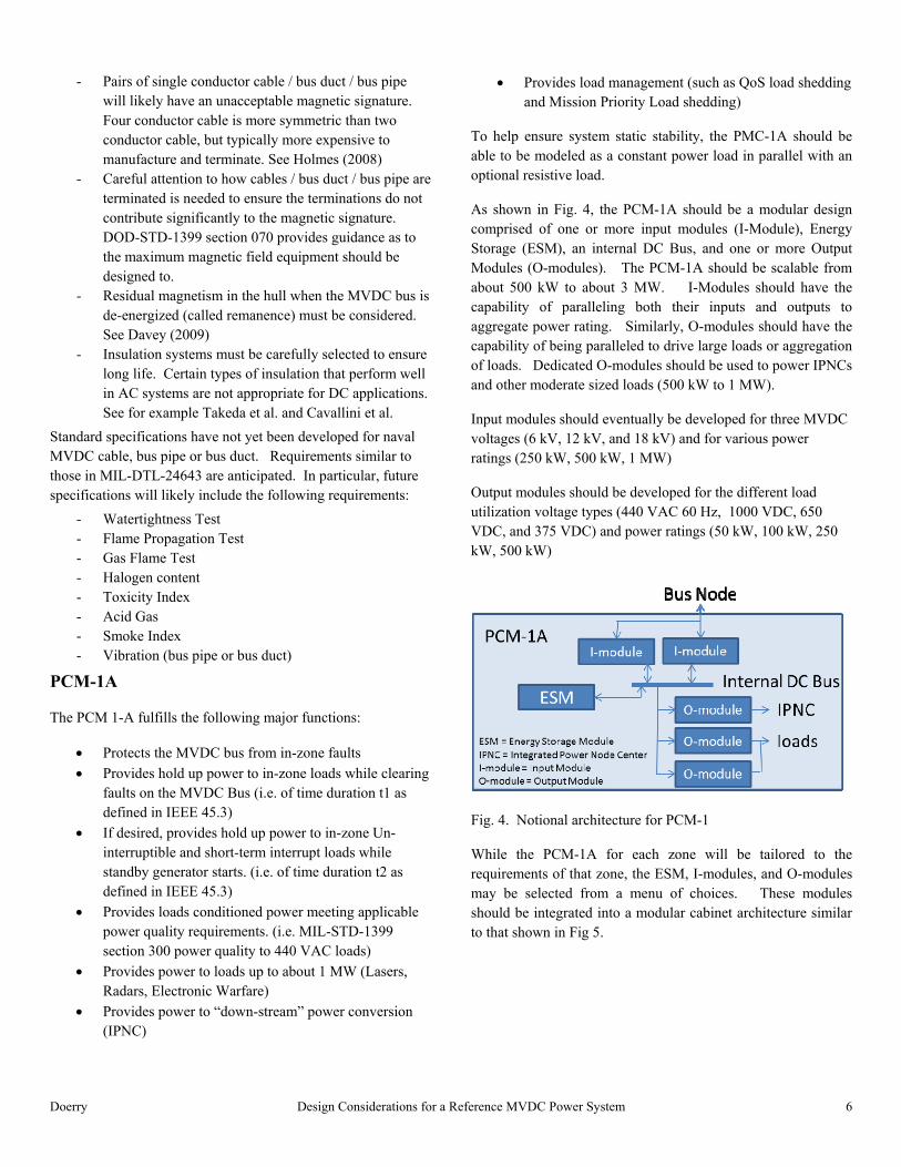
To help ensure system static stability, the PMC-1A should be able to be modeled as a constant power load in parallel with an optional resistive load.
As shown in Fig. 4, the PCM-1A should be a modular design comprised of one or more input modules (I-Module), Energy Storage (ESM), an internal DC Bus, and one or more Output Modules (O-modules). The PCM-1A should be scalable from about 500 kW to about 3 MW. I-Modules should have the capability of paralleling both their inputs and outputs to aggregate power rating. Similarly, O-modules should have the capability of being paralleled to drive large loads or aggregation of loads. Dedicated O-modules should be used to power IPNCs and other moderate sized loads (500 kW to 1 MW).
Input modules should eventually be developed for three MVDC voltages (6 kV, 12 kV, and 18 kV) and for various power ratings (250 kW, 500 kW, 1 MW)
Output modules should be developed for the different load utilization voltage types (440 VAC 60 Hz, 1000 VDC, 650 VDC, and 375 VDC) and power ratings (50 kW, 100 kW, 250 kW, 500 kW)
Fig. 4. Notional architecture for PCM-1
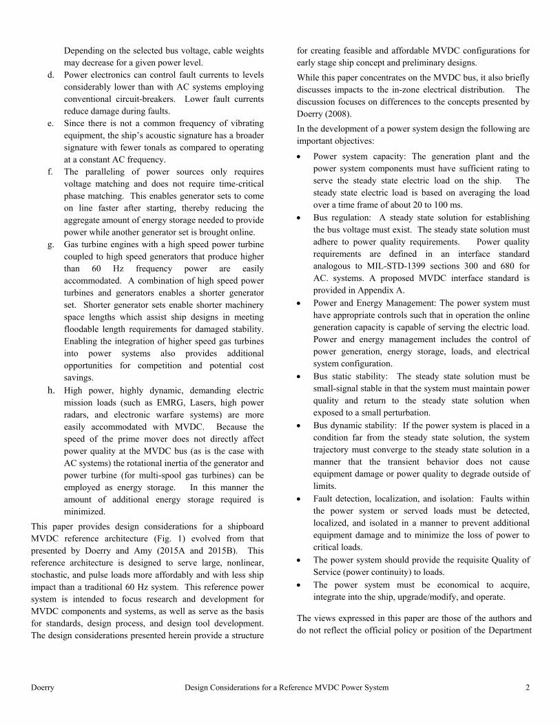
While the PCM-1A for each zone will be tailored to the requirements of that zone, the ESM, I-modules, and O-modules may be selected from a menu of choices. These modules should be integrated into a modular cabinet architecture similar to that shown in Fig 5.
Doerry Design Considerations for a Reference MVDC Power System 7
Fig 5. PCM 1A modular cabinet architecture
PCM-1B / Electromagnetic Rail Gun
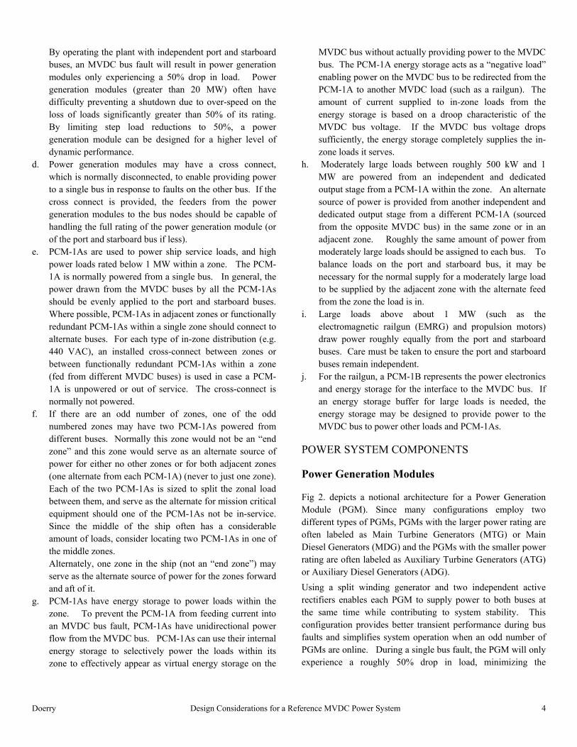
Fig 6. depicts a notional architecture for an electromagnetic railgun. Two PCM-1Bs buffer the power required by the pulse forming networks (PFN) from the power system. The PCM-1B is anticipated to have the same general architecture as the PCM-1A (and should employ common components to the degree practical), but be capable of power levels greater than 10 MW. Each PCM-1B is normally powered by an independent bus. The PCM-1B includes power conversion to drive the mount (train and elevation motors, loading system, etc.) and the PFNs. The PCM-1B may include Energy Storage to provide the capability to power the PFNs until sufficient PGMs are brought online as well as to enable higher power ramp rates than the PGMs can support. To enable use of the energy storage in the PCM-1B for loads other than the EMRG, power flow between the MVDC bus and the PCM-1B is bidirectional.
In some applications, a PCM-1B may be desirable to provide bidirectional Energy Storage capability to the MVDC bus. In this case, the PCM-1B would consist of I-Module(s) and Energy Storage and not have any O-Modules. Such a PCM-1B configuration could be useful for powering an MVDC bus for extended periods of time (greater than t2) for either fuel economy reasons, or for survivability reasons. If for survivability, these ES / I-Module only PCM-1Bs will likely be located in the first and/or last zones.
The three disconnects depicted in Fig 6. offer the opportunity to power both PFNs from a single bus (at a lower firing rate) in the case of a fault on one of the buses. The cross-connect disconnect is normally open.
Fig. 6. EMRG Notional Architecture
Integrated Power Node Center (IPNC)
The IPNC incorporates power conversion Input and Output Modules to provide power to un-interruptible loads, to 400 Hz. loads, to loads requiring custom power quality, and to loads requiring dedicated high quality power. Zones may have multiple IPNCs. For the MVDC architecture MIL-PRF-32272 should be modified to incorporate 1000 VDC input modules and provision for energy storage for ~1 second. Fig. 7. depicts one implementation of an IPNC based on MIL-PRF-32272.
The implementation of point of use power conversion with an IPNC enables the elimination of dedicated special use (such as 400 Hz.) power distribution systems.
The 1000 VDC input module of the IPNC provides the power system designer a choice of using a 1000 VDC or a 440 VAC as the primary interface between the PCM-1A and the IPNC; the choice to be based primarily on availability and cost. A second 440 VAC interface power interface enables powering from an adjacent zone in the event the in-zone PCM-1A becomes inoperative. Using 440 VAC from an adjacent zone is intended to provide the lowest cost solution to provide power to vital loads in both zones should one PCM-1A become inoperative; a dedicated output module in the adjacent zone PCM-1A is not required.
The energy storage in the IPNC allows 440 VAC Load Centers in zone and in the adjacent zone to reconfigure within ~1 second without impacting un-interruptible loads.

Doerry Design Considerations for a Reference MVDC Power System 8
Fig. 7. IPNC Example
PCM-SP
The PCM-SP is power conversion for interfacing the MVDC buses with shore power. The shore power interface includes not only power quality attributes, but also grounding, galvanic isolation, and fault protection requirements. On the MVDC buses, the PCM-SP is a functional equivalent to a PGM.
Propulsion Motor Modules
Fig 8. depicts a notional architecture for a Propulsion Motor Module (PMM). The PMM is anticipated to consist of two independent sets of motors and drives. To enhance reliability and survivability, one set is normally powered from port bus and the other from the starboard bus. The motors, while independent electrically, may be manufactured as a single unit. A cross connect, normally left open, would enable a PMM in the case of a faulted MVDC bus to be powered from a single bus, subject to load-flow limitations. Depending on the requirements for mobility following battle damage, it may be possible to meet survivability requirements without the three disconnects depicted in Fig. 8. The disconnects in the bus nodes would still be required to enable isolation of the PMM for maintenance.
If the drives are bi-directional, dynamic braking resistors may be eliminated. In this case, circuit breaker functionality must be provided in either the drive or the corresponding Bus Nodes.
Fig. 8. PMM Notional Architecture
60 Hz. AC Distribution
Within a zone, the 60 Hz. AC distribution system will serve most of the legacy AC loads from the 440 VAC output inverters of the PCM-1A. The load centers will likely employ traditional AC circuit breakers, but must be configured to coordinate properly with a reduced fault current. The 440 VAC output inverters of the PCM-1A will current limit at the rated current.
Survivability analysis and requirements will drive the actual design of the in-zone distribution system.
POWER SYSTEM CAPACITY
The total power rating of the installed PGMs should have the capacity to provide the maximum of the sum of ship service electrical load (steady state), margin, Service Life Allowance (SLA) and propulsion load (including applicable speed/power margins) for any operating condition. Margin addresses uncertainty in the ship service electrical load during the design and construction of the ship. SLA ensures sufficient capacity as ship service load equipment ages (and potentially becomes less efficient) and for modernization. Note that the maximum is calculated based on an operating condition; the maximum ship service electrical may or may not occur when the ship is required to have the maximum propulsion load. The ship service electrical load for each operating condition is calculated as part of the Electric Power Load Analysis (EPLA) using one of the methods described in T9070-A3-DPC-010/310-1 (formerly DS 310-1 rev 1).
Often, the maximum sum of ship service electric load, margin, SLA and propulsion load is expected to occur infrequently in-service. It may be more cost effective to fix the total power rating of the installed PGMs to below the calculated maximum sum of ship service load, margin, SLA and propulsion load. For a small percentage of the projected operating time, the imbalance in power capacity and load would be addressed by using energy storage, operating slower (reducing propulsion power), by managing loads, or some combination of these.

Doerry Design Considerations for a Reference MVDC Power System 9
The loss of use of the largest generator set for any reason (failure, maintenance, etc.) must not impact the ability of the electric power generation plant to concurrently supply the maximum of the sum of ship service electric load, margin and SLA, and power to meet minimum operational mobility requirements (as defined by regulations or the customer).
The electric plant control system must prevent overloading of the generators. During restricted maneuvering, the electric plant control system must have the ability to maintain power to the propulsion motors by managing energy storage or implementing load shedding so as to prevent overloading the generators. During non-restricted maneuvering, the electric plant control system must have the ability to prevent overloading the generators by managing the power provided to the propulsion motors prior to implementing load shedding.
Note that in traditional AC systems, overloading generators is prevented in part by assuming the maximum allowable loading of a PGM is either 0.90 or 0.95 times the PGM rating. By relying on controls to prevent generator overloading, the full rating of the PGM may be used.
The sizing and quantity of PCM-1A and IPNC input and output modules depend on the reliability of the modules, the maximum load served, and the quality of service requirements. Because power electronics current limit and do not have an overload capability, the calculation of the maximum load served must be based on short-term averages rather than the long term averages used for establishing the capacity of the PGMs. T9070-A3-DPC-010/310-1 provides several methods, including the zonal load factor method, to determine the appropriate maximum load served for zonal loads. If the inherent reliability of the input and output modules is not sufficient to achieve the requisite QoS, then additional paralleled modules may be required.
The PCM-1A capacity must also be sufficient to power mission critical loads within the zone and in adjacent cross-connected zones in the case that the PCM-1A in the cross-connected zone is inoperative. During this condition, non-mission critical loads are shed in the cross-connected zones.
The PCM-1A energy storage should have sufficient energy and power capacity to power uninterruptible and short-term interruptible loads for the amount of time it takes to clear faults on the MVDC bus. During faults on the MVDC bus, long-term interrupt loads may be shed.
If the ship is intended to be capable of operating with only a single PGM online, the PCM-1A energy storage should have sufficient energy and power capacity to power uninterruptible and short-term interruptible loads for the amount of time it takes to bring a standby PGM online (time duration t2). Without a PGM online, long-term interrupt loads may be shed.
As a first estimate, the ampacity of the port MVDC bus and the starboard MVDC bus each should be equal to or greater than that required for the limiting load flow as detailed in Appendix B. While this ensures sufficient capacity under normal conditions, a detailed load flow analysis for normal and casualty conditions may result in different values for each segment of the buses. To minimize weight and cost, the bus capacities may be limited in a manner that precludes some electric plant configurations or requires load shedding in certain casualty conditions.
BUS REGULATION
The controllers for the PGMs, PCM-1As , and PCM-1Bs should be designed to operate with MVDC bus interface steady state characteristics that enable power sharing among PGMs under normal situations and use of energy storage when there is insufficient generation online. The primary mechanism for accomplishing this is through voltage droop. Voltage droop is implemented via controls: a voltage – current characteristic of the source mimics a series resistance, without actually resulting in the losses associated with a physical resistance.
The droop characteristic coupled with an appropriate load shed strategy ensures a unique steady state solution exists for the bus voltage as long as online generation capacity is greater than the online load. With proper design of components, all steady-state power quality requirements can be met.
Under normal operation, online PGMs share power based on droop. To account for the steady-state voltage tolerance, the overall power system controller should adjust the actual power sharing by adjusting the no load voltage setting for the online PGMs.
Once PGMs reach their rated power and the bus voltage drops further, the PGMs switch modes to deliver constant power until voltage drops to where the current reaches a current limit. Below that point, the PGMs enter a current limit mode. The PGMs should not enter the current limit mode under normal operation. If a PGM current limits, load shedding or fault clearing should be initiated at the appropriate level of control to enable the PGMs to return to either droop control or constant power control.
Energy storage within the PCM-1As and PCM-1Bs provide power once the PGMs are in constant power mode. When providing power, energy storage uses a droop characteristic to share power among the online energy storage components; PGMs are providing power at a constant rated value. Once the PGMs are operating back in the droop mode, energy storage senses this via the bus voltage and start to draw current to recharge.
Doerry Design Considerations for a Reference MVDC Power System 10
Because the bus voltage and PGM/PCM current will continuously vary to a degree, establishing the reference voltage and voltage error (difference between the measured voltage and the reference voltage) for voltage regulation is generally based on an averaged value of current and voltage measurement samples over a time window. The duration of the time window for performing the averaging determines how quickly a PGM or PCM will react to a change in bus voltage. The longer the time window, the longer it will take for a change in bus voltage to impact the calculated DC voltage measurement. Hence the selection of the time window duration will impact system static and dynamic stability (transient performance).
PGM Steady State Droop Characteristic
Under normal conditions, a PGM regulates steady state voltage based on a reference voltage obtained by applying a droop characteristic to the steady state current. The PGM steady state droop characteristic is defined to be:
No Load Voltage = 1.05 times nominal system voltage (Can be adjusted by system control to ensure equal power sharing)
Voltage at rated power = 0.97 times nominal system voltage (current at 1.031 times nominal current rating) with the no load voltage at 1.05 times nominal system voltage.
Nominal current rating is rated power divided by nominal system voltage.
As the PGM steady-state current linearly increases, the PGM reference voltage drops from no load voltage to voltage at rated power. If the PGM steady-state current is greater than the current at rated power for the droop characteristic but less than 1.111 times the nominal current rating, the PGM is in a constant power mode where the reference voltage is the rated power divided by the steady-state current. If the reference voltage under constant power mode drops to 0.90 times nominal system voltage or below, the PGM then current limits at 1.111 times nominal current rating.
Energy storage characteristic for discharging
Within the PCM 1A and the PCM 1B, the energy storage steady state droop characteristic is defined to be:
No Load Voltage = 0.95 times nominal system voltage (can be adjusted by system control to enable equal power sharing)
Voltage at rated power = 0.90 times nominal system voltage with the no load voltage at 0.95 times nominal system voltage
Current limit = 1.111 times nominal current rating
Energy storage acts as a current source. If the steady-state bus voltage is above the No Load Voltage, the energy storage does not discharge. Energy Storage reference steady-state current linearly increases with respect to steady state voltage on the MVDC bus dropping from no load voltage to voltage at rated power. For PCM-1A, the current is capped to that needed to serve in-zone loads (no current drawn from or provided to the MVDC bus). For PCM-1B, if the State of Charge is above a specified threshold, the current not required for the served load (railgun) is provided back to the MVDC bus (in total, up to the current limit).
Energy storage characteristic for charging:
The energy storage steady state characteristic for charging is defined to be:
No load voltage = 0.97 times nominal system voltage
Voltage for maximum charging rate = nominal system voltage
The charging rate is a linear function of the MVDC bus steady state voltage with no current drawn at or below the no load voltage, and maximum charging rate at or above nominal system voltage.
Propulsion Motors and Other Large Load Characteristic
Propulsion motors must be able to operate over their entire speed power range and other large loads must function normally
with an MVDC bus steady state voltage within the load normal service steady state voltage range.
Consideration should be given to enabling the propulsion motor to enter a mode to dissipate power if the MVDC bus steady state voltage rises above the load normal steady state voltage range. Methods could include making the motor or drive less efficient, or energizing the dynamic braking resistor (if provided). Note that this is an abnormal situation since the MVDC bus steady state voltage should always be within the normal steady state voltage range.
As indicated above, if a bi-directional motor drive is provided, dynamic braking resistor may not be required.
POWER MANAGEMENT
In classic AC power systems, very little is required of power management. In fact, response to changes in load occurs passively. The role of power management is to ensure sufficient online generating capacity, usually a task assigned to

Doerry Design Considerations for a Reference MVDC Power System 11
Engineering Department watchstanders. What control does exist is focused on sharing load between paralleled generators, adjusting real power output through speed regulation and providing reactive power through voltage regulation. The advantages of the passive load response are that it’s simple, does not require an elaborate control system nor even communications with a machinery control system. The chief disadvantages are:
Speed and voltage regulation and machine inertia limit the load dynamics that can be supplied.
Operators must maintain the online capacity which they deem prudent.
Insufficient online capacity is remediated via brute force load shedding.
Doerry and Amy (2008) detail how the role of power management varies situationally. ‘Normal’ power management functions, as before, to ensure sufficient online capacity, perhaps autonomously. ‘Quality of Service’ (QoS) power management serves to continue providing power, in accordance with loads’ tolerance to interruptions during response to a power system fault or failure. ‘Survivability’ or ‘Mission priority’ power management is triggered when power and energy resources, for whatever reason, are insufficient to supply load and meet QoS objectives.
The actions discussed above can be implemented in a phased approach by evolving power management and controls design. Once fully implemented, required performance will likely be achievable with less installed capacity than would be otherwise needed.
In classic U.S. Navy power systems, the loads do not have an interface with power management. This has begun to change. EMALS has an interface with the machinery control system which provides a commanded power limit to EMALS. On DDG 1000 and DDG 51 Hybrid Electric Drive (HED), power for propulsion is subject to power management. The addition of a power management interface between the power system and larger loads provides another means to match online capacity in the near term with load demand. By being able to command limits to larger loads, the online capacity can be more completely exploited. This addition to the power system design capability does require communications and an additional level of controls for power management. (A reversionary behavior must be invoked by the power system and loads upon loss of communications with power management.) Adding a power management interface for the larger loads is the next step in the phased approach for implementing the first action. Advanced
mission systems must be designed to have and to act upon this interface.
A follow-on step in the phased approach is the development of an interface with combat systems controls and, specifically, mission resource planning and, ultimately, mission system cueing. Taking advantage of mission system load elasticity and energy storage/energy management, the objective of Science and Technology and Research and Development would be to develop a real-time forecast and prioritization of mission loads based upon the combat system scheduler. This load forecast, ideally, would expand the operating area for ‘Normal’ power management while more completely utilizing installed capacities, enabling modest sized generating and energy storage capacities.
SYSTEM STABILITY
For a dynamic system (such as an electrical power system) to be stable, the following three conditions must hold:
- A steady state solution that meets power quality requirements must exist
- That steady state solution must possess static stability (small-signal stability or linear stability)
- The system must be dynamically stable: when the system has an initial condition that is far from the steady state solution, the system must converge to the state steady solution while meeting transient power quality requirements and not damaging equipment. (large-signal stability)
Steady state solution
The droop characteristic described previously, coupled with an appropriate power management strategy will ensure a unique steady state solution exists. With proper design of components, the other steady-state power quality requirements can be met. Appendix A provides an example of a power quality interface standard based on a refinement of the proposed standards of Doerry and Amy (2015C).
Static Stability
The use of Bode stability techniques in power system design is well established (Flower and Hodge (2004), Williams (2004), Gholdston et.al. (1996) and Sudhoff et. al. (2003)). For a simple source and load as shown in Fig. 9, the small signal Impedance of the Source (S) and the small signal Admittance (L) of the Load are designed to ensure stability. Flower and Hodge (2004) is representative of the many references that demonstrate that this system is stable if the roots of 1 + SL (where S and L are expressed in terms of their Laplace

Doerry Design Considerations for a Reference MVDC Power System 12
transform in the form of a ratio of polynomials of the Laplace operator s) all have negative real components.
Fig. 9. Simple source – load system (Sudhoff et. al. 2003)
If we set G(s) = SL, then the problem is determining if the roots of 1 + G(s) are in the complex left hand plane. This is precisely the problem addressed by Bode diagrams. In Bode diagrams, s is set equal to jwhere is the frequency (measured in radians/sec) and j is the square root of -1. G(j) is now expressed as:
G(j) = H()ej() Where H() is the gain and () is the phase. Taking the natural logarithm of the above equation results in
ln(G(j)) = ln(H()) + j( A Bode diagram (Fig. 10) is a representation of the above equation and consists of a plot of H() (in dBs) vs. (on a logarithmic scale) and () (in degrees) vs. (also on a logarithmic scale).
Fig. 10. Bode Plot Example (Flower and Hodge 2004)
For stability, two conditions must exist. First, the gain (in dB) at the frequency where the phase is 180° must be less than 0. The difference between 0 and the gain is called the gain margin. Second, the phase at the frequency where the gain is 0 dB must not be 180°. The difference between this phase and 180° is the phase margin. In designing a power system, practice is to specify minimum gain and phase margins. Since G(s) = SL is a function of the sources, loads, and the operating point, it is not obvious how one can create a generalized requirement for sources and loads such that an arbitrary ship configuration at an arbitrary operating point is guaranteed to be stable. In particular, all of the MVDC loads in the MVDC reference architecture will predominately exhibit a constant power characteristic. When linearized around a given operating point, this constant power characteristic has a negative slope of voltage vs current which is often called a “negative incremental resistance.” This negative incremental resistance has a destabilizing influence on the power system. Insight on this issue can be gained if the DC source and non-linear load can be modeled as shown in Fig. 11.
Fig 11. RLC Model
This circuit is described by the following equations:
(1a)
(1b)
Differentiate Eq. 1a.
C (1c)
Substitute Eq. 1a and 1c into Eq. 1b
(2a)
Rearrange terms:
(2b)
Linearize around the steady state voltage V0
+
VGg V( )L
L R
CiG
VL

Doerry Design Considerations for a Reference MVDC Power System 13
(3a)
(3b)
(3c)
(3d)
Substitute into Eq. 2b
(4a)
Cancel and rearrange terms:
0 1 (4b)
For Eq. 4b to be stable, all of the coefficients must be of the same sign. Since LC is always positive, all of the terms must be positive. Hence the stability criteria are:
1 0 (5a)
0 (5b)
Assume g(VL) takes on the following form ....
(6a)
where 0 (6b)
h represents the conductance of a resistive component of g(VL) in parallel to the constant power (P) component.
Taking the derivative .....
(6c)
The conditions for stability are ...
1 0 (7a)
0 (7b)
Note that if the condition is satisfied for h = 0, then the condition will be satisfied for any positive value of h. Also, a bigger h can stabilize the constant power load term.
1 0 (8a)
0 (8b)
Now R is based on the droop characteristic of the source.
1 (9)
R is the coefficient of i in Eq. 9:
(10)
In examining this relationship, the numerator is likely to be roughly the same as but the denominator P0 will be greater than or equal to P and d will be on the order of 0.08. This implies that the first stability criteria will always be met with a constant power load. The second condition for stability can be restated as:
(11)
If the control algorithm and the characteristics of the PGM are designed to meet the more stringent requirement:
(12)
Then the system will be stable for all constant power loads equal to or less than the rating of the generator. Since VB, VNL and d are already specified, stability depends on the ratio of C to L.
If a composite system is made up of paralleled PGMs and paralleled constant power loads (with the composite load power less than or equal to the composite generator rating), then the composite system will also be stable if the above condition holds for each PGM. In this way, small-signal stability can be specified for a PGM independent of the actual system it is integrated into.
Now this analysis only works if a PGM can actually behave as an RLC circuit as modeled above. In particular, can controls make the PGM appear as an RLC circuit with a C to L ratio that ensures stability? Can higher order dynamics be controlled over a sufficient bandwidth to ensure phase and gain margins are always met with the composite system?
For a generator with a controlled rectifier, the steady-state DC voltage at the terminal is given by Eq. 13:
√ cos (13)
In this relationship, ωe is a variable, the generator’s speed. Laf, lc and ra are fixed for a machine’s design. If and α are ‘adjustable’. This steady-state equation presents a “natural” droop (coefficient of I that may or may not correspond to the

Doerry Design Considerations for a Reference MVDC Power System 14
desired droop characteristic . Without the PGM controls
adjusting the values of ωe, If and α, the output voltage will decrease with increasing current. The generator controls can however, adjust the values of ωe, If and α so that in the steady state the generator exhibits the desired droop characteristic. Now the time constants associated with ωe and If are on the order of 1 to 10 seconds. (FFG 7 1 MW gensets open circuit time constant (associated with If) listed as 4.09 seconds, DD 963 2 MW genset open circuit time constant listed as 2.9 seconds) (gas turbines are to return to within 1% of final steady-state speed within 5 seconds of a change in load – MIL-E-17341C, diesels have a 2 second recovery time for a transient). Only α can be adjusted quickly for a faster response. However, if α is near 0, then it cannot be used to increase the DC voltage. Thus to preserve dynamic performance, α must be somewhat above 0 initially to enable cos α to rapidly increase. For example if we normally operate with cos α = 0.90, α would equal about 26° which would likely result in the generator experiencing significant current harmonic distortion and heating.
While the above gives the steady-state model of a genset, we still need to determine the relationship between the genset machine parameters and the equivalent L and C of the RLC model.
The above analysis is based on a controlled rectifier with phase control. An alternative would be to use an uncontrolled multi-phase rectifier (perhaps 6 phase for a 12 pulse rectifier) followed by a DC to DC converter. This DC to DC converter could switch at a much higher frequency, reducing the required size of the link inductor. The switching period of this converter would not have as large an impact on the harmonics seen by the generator. Furthermore, the output voltage can be adjusted at the rate of the switching frequency.
Dynamic Stability
When a sudden load is applied or removed from a system with multiple paralleled sources, the source with the fastest dynamic response will initially experience high transient currents (it will try to handle the change in load by itself since the other sources are slower). If these currents are not sufficiently controlled by the source, then the source may trip offline or may suffer damage. If all the sources are “slow” then transient power quality requirements may not be met. Within the MVDC reference architecture, the converters associated with the Energy Storage in the PCM-1As and PCM-1Bs should all have roughly the same dynamic time constant that is faster than the dynamic time constant of the fastest generator set. This will enable the controls of the generator sets to keep the generator sets
operating in a “safe” operating area (avoid damage and tripping offline) while still preserving the transient power quality on the MVDC bus. Keeping the dynamic time constants of the energy storage roughly the same will prevent the fastest ESM from experiencing the high transient currents.
FAULT DETECTION, LOCALIZATION, AND ISOLATION
The use in MVDC power systems of traditional electromechanical circuit breakers common in AC systems is complicated by the need to extinguish the arc once the circuit breaker contactors open. In an AC circuit breaker, the natural zero crossing of the current waveform provides a mechanism for extinguishing the arc and establishing a voltage barrier to prevent the arc from re-striking. DC circuit breakers cannot take advantage of the current zero crossing. Hence, electromechanical circuit breakers are limited in the amount of DC current they can interrupt. Several manufacturers are developing hybrid DC circuit breakers that use semiconductors to shunt the current when the electro-mechanical breaker opens, thereby eliminating the arc. Although these hybrid DC circuit breakers are anticipated to work as part of the bus nodes, they will likely cost more than traditional AC breakers and may require more volume. Hence the proposed system employs circuit breakers only for power system equipment that are sources.
Since all the sources of MVDC are power electronic based, fault currents can be limited by controlling the power electronics, enabling alternate strategies such as employing less expensive disconnect switches to reconfigure the plant once the power electronics have halted current flow. This strategy does require zonal energy storage to power loads while the fault is cleared on the MVDC bus. Challenges of this strategy confronting system designers of a MVDC system is to understand the behavior of the MVDC system to accurately detect a bus fault, determine the location of the fault within the system, determine the best way to isolate the fault, remove power from the bus, isolate the fault, and then re-energize the reconfigured bus. In the case of ground faults, the energy stored in the bus capacitance will likely have to be deliberately dissipated.
Should the cost, weight, and volume of DC circuit breakers become comparable to AC circuit breakers, more extensive use of DC circuit breakers in the reference architecture may be warranted. More extensive use of DC circuit breakers may simplify fault detection, localization, and isolation as well as reduce the amount of energy storage required in PCM-1As.

Doerry Design Considerations for a Reference MVDC Power System 15
Localization of faults on an MVDC bus must consider the bi-directional nature of power flow of a zonal system. In AC zonal systems, a Multifunction Monitor (MFM) assists in the localization of faults. An analogous component may be needed for an MVDC system.
GROUNDING SYSTEM
One of the key technologies needed for an MVDC system is an affordable, reliable method to provide a ground reference for an MVDC shipboard power system. This grounding method must account for multiple sources of MVDC power on the bus that may or may not be online at any one time.
Desirable attributes of the grounding system include the ability to continue safe operation with one line to ground fault, the ability to detect and locate line to ground faults, minimizing currents in the hull, and avoiding high line to ground voltages that can stress and reduce the service life of cable insulation. Previous research on grounding systems include Graber et al. (2014), and Jacobson and Walker (2007). To date, of the many possible ways of grounding an MVDC system, a preferred solution for MVDC system grounding has not been established.
QUALITY OF SERVICE
Quality of Service (QoS) is a measure of the reliability of the power system measured by the mean time between service interruptions (MTBSI). A service interruption is viewed from the load; it occurs when the power quality falls outside of normal limits for a duration longer than the load can tolerate. For future ships employing electric weapons, QoS is critically important to ensuring the ship’s combat effectiveness is not impeded by low reliability of the power system. For critical loads, a MTBSI of between 20,000 and 30,000 hours is desired.
The duration that a load can tolerate an interruption is measured relative to two power system characteristics: t1 which is the characteristic time to reconfigure the electrical system following fault detection, localization, and isolation, and t2 which is the characteristic time to bring a standby generator online. Loads which cannot tolerate a service interruption of duration t1 are “uninterruptible loads” and are provided uninterruptible power. Loads that can tolerate an interruption of duration t1 but cannot tolerate an interruption of t2 are “short-term interrupt loads” where the power system’s control system’s objective is to limit interruptions to duration t1 or less. The remaining loads are “long-term interrupt loads” where the power system’s control system’s objective is to limit interruptions to duration t2 or less.
A load tolerates an interruption when its basic functionality is not lost. For example, a freezer for frozen stores has a significant amount of thermal inertia and could tolerate interruptions of time t2, hence the freezer would be considered a “long term interrupt load.” For a “long-term interrupt load,” power interruptions of duration less than t2 are not considered service interruptions. Computers for the combat system would likely not tolerate more than a few milliseconds of power interruption, likely making them “uninterruptible loads.” The classification of a load into a QoS category is both a function of the tolerance of a load to power interruptions and of the capability of the power system.
For the power system designer, reducing t1 and t2 will likely change the category of some loads from “uninterruptible” to “short-term interruptible” and from “short-term interruptible” to “long-term interruptible.” This re-categorization can reduce the amount of required redundancy and energy-storage required to ensure QoS. However, reducing t1 and t2 also has a cost. Hence the optimal approach for establishing t1 and t2 is an economic one and the values of t1 and t2 should not be established prior to conducting an economic and technical analysis.
MVDC SYSTEM RISKS
The U.S. Navy has identified the following risks for implementing an MVDC electric power system: (Markle 2016)
If the MVDC electric power system is not fully integrated both electrically (from generators to users including shared distribute energy storage for multiple functions), and logically (under a cyber secure real time advanced control system integrated with the combat system), then it will not be possible to implement an effective power system on future surface combatants with multiple high power and pulsed weapons and sensors.
If the power density of a shipboard system is not sufficiently high, then a cost effective MVDC power system may not be viable for future surface combatants.
If the ship power system engineering and design standards, specifications, requirements and practices are inadequate, then non-standard approaches will result and increase acquisition and support costs
If available electrical engineering capability and industrial base are insufficient to support development and implementation, then the Navy will not be able to make informed decisions and procure and support an advanced approach for future ship power systems

Doerry Design Considerations for a Reference MVDC Power System 16
If supporting technologies (advanced circuit protection, multi-function energy storage, advanced combat power controls) and architectural approach are inadequate or not successfully developed, then fallback approaches must be used with associated increases in size and weight.
A number of initiatives are being proposed and funded to address these risks in time to enable integrating a cost effective MVDC power into future surface combatants. Some standards, such as IEEE Std 1709-2010 and IEEE Std 45.3-2015, currently address MVDC implementations to a limited extent. IEEE Std 1826-2012 provides guidance for zonal electrical distribution systems.
USE OF THE REFERENCE ARCHITECTURE
The power system architecture that will eventually be integrated into a future surface combatant will undoubtedly differ from that presented here. This reference architecture is intended to provide a framework or guide for focusing research and development and for developing design tools, equipment, software, specifications, and standards. As these efforts progress and more is learned, improvements to the reference architecture are anticipated. Eventually, the reference architecture will be documented in a design practices and criteria manual and other standards and specifications.
The reference architecture is intended as a guide / starting point and its application should not prevent the designer from optimizing the power system architecture for a given application. Modifications should be incorporated if QoS and survivability requirements can be achieved more affordably.
CONCLUSIONS
This paper describes an MVDC power system reference architecture to support future surface combatants with high power and pulse mission critical loads in an affordable manner. This architecture addresses the highly dynamic behavior required to support these mission critical loads with the requisite QoS. An MVDC interface standard is also proposed to define power quality.
REFERENCES
Cavallini, a, D. Fabiani, G. Mazzanti and G.C. Montanari, “A General Model for Life Estimation of Cables under Dc Stress with Voltage-Polarity Inversions Accounting for Space-Charge Effects,” Proceedings of 2001 International Symposium on Electrical Insulating
Materials, 2001. (ISEIM 2001), Himeji, Japan, 22 Nov. 2001.
Davey, Kent R., “Calculation of Magnetic Remanence,” IEEE Transactions on Magnetics, Vol. 45., No 7., July 2009. pp. 2907-2911.
DOD-STD-1399 section 070, “DC Magnetic Field Environment,” Interface Standard for Shipboard Systems, 26 February 1979.
Doerry, CAPT Norbert USN, "In-Zone Power Distribution for the Next Generation Integrated Power System," Presented at ASNE Advanced Naval Propulsion Symposium 2008, Arlington, VA, Dec 15-16, 2008.
Doerry, CAPT Norbert USN and Dr. John Amy, "Functional Decomposition of a Medium Voltage DC Integrated Power System," Presented at the ASNE Shipbuilding in Support of the Global War on Terrorism Conference, Biloxi, MS, April 14-17, 2008
Doerry, Dr. Norbert H. and Dr. John V. Amy Jr., "The Road to MVDC," Presented at ASNE Intelligent Ships Symposium 2015, Philadelphia PA, May-20-21, 2015 (2015A)
Doerry, N and J. Amy Jr., "MVDC Shipboard Power System Considerations for Electromagnetic Railguns," 6th DoD Electromagnetic Railgun Workshop, Laurel MD, Sept 15-16, 2015 (2015B)
Doerry, Dr. Norbert and Dr. John Amy, "DC Voltage Interface Standards for Naval Applications," Proceedings of IEEE ESTS 2015, Alexandria, VA, June 22-24, 2015 (2015C)
Flower, J.O., and C.G. Hodge, “Stability and transient-behavioural assessment of power-electronics based dc-distribution systems,” Proceedings of the 2004 WSEAS Conference on: Electroscience and Technology for Naval Engineering and All-Electric Ship, Vouliagmeni, Athens, Greece, July 12-14, 2004, paper 487-217.
Gholdston, E.W., K. Karimi, F.C. Lee, J. Rajagopalan, Y. Panov, and B. Manners, “Stability of Large DC Power Systems Using Switching Converters, With Application to the International Space Station,” NASA Technical Memorandum 107281, IECEC 96-96079, July 1996.
Graber, L., S. Pekarek, M. Mazzola, "Grounding of Shipboard Power Systems - Results from Research an Preliminary Guidelines for the Shipbuilding Industry," ESRDC Technical Report, Contract N0014-08-1-0080, February 2014.
Greene, William C., “Evaluation of non-intrusive monitoring for condition based maintenance applications on US Navy propulsion plants,” Thesis, MIT Departments of

Doerry Design Considerations for a Reference MVDC Power System 17
Ocean Engineering and Mechanical Engineering, June 2005.
Holmes, John, J., Reduction of a Ship’s Magnetic Field Signatures, Synthesis Lectures on Computational Electromagnetics, Morgan & Claypool Publishers, 2008.
IEEE Std 45.3-2015, "IEEE Recommended Practice for Shipboard Electrical Installations - Systems Engineering," Approved 11 June 2015.
IEEE Std 1709-2010, "IEEE Recommended Practice for 1 to 35 kV Medium Voltage DC Power Systems on Ships," Approved June 2010.
IEEE Std 1826- 2012, "IEEE Standard for Power Electronics Open System Interfaces in Zonal Electrical Distribution Systems Rated Above 100 kW," Approved 22 June 2012.
Jacobson, Boris, and John Walker, "Grounding Considerations for DC and Mixed DC and AC Power Systems," Naval Engineers Journal, Volume 119, Number 2, 1 October 2007, pp. 49-62.
Markle, Steve, “Electric Ships Executive Steering Group” presentation of 14 April 2016.
MIL-DTL-24643, “Detail Specification, Cables, Electric, Low Smoke Halogen-Free, For Shipboard Use General Specification For,” 11 July 2011.
MIL-PRF-32272, “Integrated Power Node Center,” Performance Specification, 29 Oct 2007.
MIL-STD-1399 section 300, “Electric Power, Alternating Current,” Department of Defense Interface Standard, 24 April 2008.
MIL-STD-1399 section 680, “High Voltage Electric Power, Alternating Current,” Department of Defense Interface Standard, 24 Apr 2008.
Sudhoff, S.D., S.F. Glover, S.H. Zak, S.D. Pekarek, E.J. Zivi, D.E. Delisle, and D. Clayton, “Stability Analysis Methodologies for DC Power Distribution Systems,” Presented at the Thirteenth International Ship Control Systems Symposium (SCSS) in Orlando, Florida on 7-9 April 2003.
T9070-A3-DPC-010/310-1, “Electrical Power Load Analysis (EPLA) for Surface Ships,” NAVSEA Technical Publication, dated 7 Sep 2012 (Rev 1).
Takeda, Toshinao, Hiroshi Suzuki, and Tatsuki Okamoto, “Correlation Between Space Charge Distribution under DC Voltage and Dielectric Breakdown Properties in XLPE under Impulse Voltage Superposed onto DC Voltage,” Proceedings of 2001 International Symposium on Electrical Insulating Materials, 2001. (ISEIM 2001), Himeji, Japan, 22 Nov. 2001.
Williams, Michael L, “Measurement of Stability Margins in Single-Phase and Polyphase Switchmode Power Systems – A Tutorial Introduction,” Presented at ASNE EMTS 2004, Jan 27-29, 2004.
APPENDIX A: Proposed MVDC interface standard:
Requirements
Nominal System Voltage: 6 kV, 12 kV, or 18 kV
Source steady-state voltage range (0 to rated power): 0.90 x nominal to 1.05 x nominal
Source steady-state voltage range (constant current): 0 to 0.90 x nominal
Source steady state-voltage tolerance: 0.5% rms of nominal Voltage.
Source maximum steady state-voltage ripple: 3.5% rms of nominal Voltage.
Load normal service steady state voltage range: 0.84 x nominal to 1.06 x nominal
Load abnormal service steady state voltage range: 0 to 0.84 x nominal, 1.06 to 1.10 x nominal
Worst Case voltage offset from Positive Terminal to Ground: 1.10 x nominal
Worst Case voltage offset from Negative Terminal to Ground: - 1.10 x nominal
Load Voltage transient Tolerance: ±10.0% of nominal voltage
Source Voltage transient Tolerance: ± 8.0% of nominal voltage
Voltage transient Recovery Time: 15 ms
Load voltage interruption Tolerance time: 5 ms
Maximum Voltage Spike (normal operation) : 2 times nominal voltage (Line to Line and Line to Ground)
Voltage Spike Waveform: (see MIL-STD-1399-300B figure 6) 1.2 μs x 50 μs
Load maximum current ripple: CE101 limit for submarine applications, DC, from MIL-STD-461

Doerry Design Considerations for a Reference MVDC Power System 18
Load maximum current rate of change (no control negotiation): 2 A / ms
Load maximum current rate of change (control negotiation): 2 to 10 A / ms
Load maximum pulse load (no control negotiations)
1.2 MW
Load maximum inrush current: 1.5 x Rated Current
Minimum Load DC Resistance to Ground:
6 kV: 1200 kΩ (qualification of new equipment) 800 kΩ (in-service conditions)
12 kV: 2400 kΩ (qualification of new equipment) 1600 kΩ (in-service conditions)
18 kV: 3600 kΩ (qualification of new equipment) 2400 kΩ (in-service conditions)
Maximum Load leakage current to Ground: 8 mA rms (qualification of new equipment) 15 mA rms (in-service conditions)
Definitions
Nominal System Voltage: The design system DC voltage. Used as a reference for establishing other power quality requirements.
Source steady-state voltage range (0 to rated power): The allowable variation in the system DC voltage measured at the output of an online source under normal droop operation and constant power mode. This range does not account for potential voltage loss in the distribution system.
Source steady-state voltage range (constant current): The allowable variation in the system DC voltage measured at the output of an online source under current limit operation. This range does not account for potential voltage loss in the distribution system.
Source steady state-voltage tolerance: When operating in droop, the maximum deviation of the steady-state voltage measured at the output of an online source from the reference voltage obtained by applying the droop characteristic to the load current.
Source maximum steady state voltage ripple: The rms value of the non-DC component of the voltage measured at the output of an online source. Ripple is measured with respect to average voltage over a 100 ms moving time window. The time interval between the starts of time windows shall not exceed 20 ms. The sampling rate shall be sufficient to accurately measure the highest significant frequency component.
Load normal service steady state voltage range: The range of steady state DC voltage that when applied to loads (with the source maximum steady state voltage ripple), the loads are required to work properly. This range accounts for potential voltage drop in the distribution system as well as the Source steady-state voltage range.
Load abnormal service steady state voltage range: The range of steady state DC voltage that when applied to loads (with voltage ripple ranging from 0 to the Source maximum steady state voltage ripple) the loads are not damaged. Loads may lose functionality as long as the loss of functionality does not directly result in damage to other equipment or injury to personnel.
Worst Case voltage offset from Positive Terminal to Ground: In the case that the Negative Terminal experiences a ground-fault, or in the case of a ground fault in a power source, the highest magnitude voltage with respect to ground expected on the Positive Terminal.
Worst Case voltage offset from Negative Terminal to Ground: In the case that the Positive Terminal experiences a ground-fault, or in the case of a ground fault in a power source, the highest magnitude (negative) voltage with respect to ground expected on the Negative Terminal.
Load Voltage transient Tolerance: Maximum permitted departure from the final steady-state voltage during transient conditions for which the load must remain fully operational.
Source Voltage transient Tolerance: Maximum permitted departure from the final steady-state voltage during transient conditions for a single source with the sudden application of 80 percent continuous rated load in one step, and with the sudden removal of 70 percent continuous rated load from a 80 percent continuous rated load starting point.
Voltage transient Recovery Time: The maximum time for the voltage waveform at the source to return to the
range specified by the Source steady-state voltage range (0 to rated power) and Source maximum

Doerry Design Considerations for a Reference MVDC Power System 19
steady state voltage ripple. The Voltage transient recovery time is characterized by the time constants associated with voltage regulation of the sources.
Load voltage interruption Tolerance time: The duration of power interruption that a load can tolerate without any change in operation and without damage.
Maximum Voltage Spike (normal operation) : The highest magnitude of a voltage spike between the positive terminal and the negative terminal, and each of the terminals and ground that when applied to the load or power system component, does not result in damage to the load or power system component and the load/power system component maintains complete functionality.
Voltage Spike Waveform: A description of the shape of the voltage spike used in conjunction with the maximum voltage spike.
Load maximum current ripple: The magnitude of the AC components of the current waveform.
Load maximum current rate of change (no control negotiation): The maximum rate of change of the current waveform for a load if a larger value has not been pre-negotiated between the load and the electric plant control system. The change is calculated as the difference between the average value of the current measurements over the first half of a window and the average value of the current measurements over the second half of a window divided by half the time window duration. The maximum window duration is 10 ms and should consist of a minimum of forty current measurement samples. The time interval between the starts of successive time windows shall not exceed 20% of the time window duration.
Load maximum current rate of change (control negotiation): The maximum rate of change of the current waveform for a load that can be negotiated between the load and the electric plant control system. The rate of change is calculated using the same method
as for the “load maximum current rate of change (no control negotiation).”
Load maximum pulse load (no control negotiations): The maximum change in power allowable for a load if a larger value has not been pre-negotiated between the load and the electric plant control system. The change is calculated as the difference between the minimum and maximum load over a moving time window of 1
second in duration. The time interval between the starts of time windows for calculating the difference shall not exceed 50 ms. The 1s time window is divided into 200 equal sub-windows of 5 ms each. The average load is calculated for each sub-window using a minimum of 20 samples. The minimum load is that of the sub-window with the lowest average load and the maximum load is that of the sub-window with the highest average load.
Load maximum inrush current: The peak instantaneous current which flows upon energizing the load or part thereof.
Minimum Load DC Resistance to Ground: The minimum
DC resistance from each terminal of the load to ground.
Maximum Load leakage current to Ground: The maximum rms value of the leakage current to ground. Leakage current is the difference between the instantaneous electrical currents entering and leaving a device through its power terminals.
APPENDIX B: Calculating Limiting Load Flow
This appendix details a method for calculating a limiting load flow for the MVDC bus. It presumes the bus is not a ring bus. The limiting load flow is a higher bound on the power (which can be translated into current) that would be expected to flow in a segment of the main bus. For the reference architecture, this main bus corresponds to either the port or starboard bus.
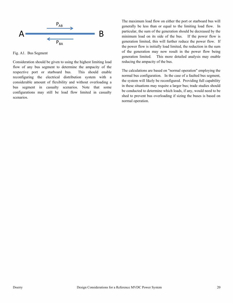
Consider a bus segment as depicted in Fig. A1. The power flow from A to B is denoted by PAB. Similarly the power flow from B to A is denoted by PBA. The limiting load flow in direction PAB.is the minimum of the sum of all generation sources connected to the A side of the bus and the sum of all the loads connected to the B side of the bus. If the sum of the generation is the lower value, the power flow is generation limited. Otherwise the power flow is load limited. When calculating the sum of the loads, the load for a PCM-1A should be assumed to be sum of the ratings of its input modules. For large loads connected directly to the MVDC bus, such as the railgun and propulsion motors, assume they are drawing their maximum power from the bus when configured normally. The limiting load flow in direction PBA is calculated in an analogous way. The limiting load flow for the bus segment is the maximum of the load flow in direction PAB and PBA.
Doerry Design Considerations for a Reference MVDC Power System 20
Fig. A1. Bus Segment
Consideration should be given to using the highest limiting load flow of any bus segment to determine the ampacity of the respective port or starboard bus. This should enable reconfiguring the electrical distribution system with a considerable amount of flexibility and without overloading a bus segment in casualty scenarios. Note that some configurations may still be load flow limited in casualty scenarios.
The maximum load flow on either the port or starboard bus will generally be less than or equal to the limiting load flow. In particular, the sum of the generation should be decreased by the minimum load on its side of the bus. If the power flow is generation limited, this will further reduce the power flow. If the power flow is initially load limited, the reduction in the sum of the generation may now result in the power flow being generation limited. This more detailed analysis may enable reducing the ampacity of the bus.
The calculations are based on "normal operation" employing the normal bus configuration. In the case of a faulted bus segment, the system will likely be reconfigured. Providing full capability in these situations may require a larger bus; trade studies should be conducted to determine which loads, if any, would need to be shed to prevent bus overloading if sizing the buses is based on normal operation.
A BPAB
PBA