e65_66 model redesign
TRANSCRIPT
8/3/2019 E65_66 Model Redesign
http://slidepdf.com/reader/full/e6566-model-redesign 1/101
BMW Service Aftersales Training
Participant's ManualE65/E66 Model Redesign

8/3/2019 E65_66 Model Redesign
http://slidepdf.com/reader/full/e6566-model-redesign 2/101
The information contained in this Participant's Manual is intended solely for the participants of this seminar run by BMW Aftersales Training.
Refer to the latest relevant "BMW Service" information for any changes/supplements to theTechnical Data.
Information status: October 2004
© 2004 BMW GroupAftersales Training, München, Germany.Reprints of this manual or its parts require the written approval of BMW Group,München.
8/3/2019 E65_66 Model Redesign
http://slidepdf.com/reader/full/e6566-model-redesign 3/101
Participant's ManualE65/E66 Model Redesign
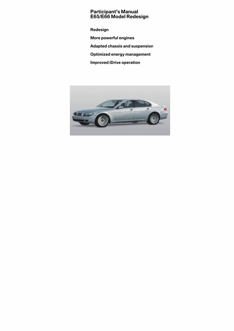
Redesign
More powerful engines
Adapted chassis and suspension
Optimized energy management
Improved iDrive operation

8/3/2019 E65_66 Model Redesign
http://slidepdf.com/reader/full/e6566-model-redesign 4/101
Information on this Participant's Manual
Symbols used
The following symbols are used in this Participant's Manual to facilitatebetter comprehension and to draw attention to important information.
3 contains information for better understanding of the describedsystems and their functions.
1 identifies the end of an item of information.
Current content of Participant's Manual
In view of theconstant further developments in thedesignandequipmentof BMW vehicles deviations may arise between this Participant's Manualand the vehicles made available as part of the training course.
The background material refers exclusively to left-hand drive vehicles.The controls are in part arranged differently in right-hand drive vehiclesthan shown on the graphics in the Participant's Manual.
Additional information sources
You will find further information on the individual vehicle topic in the BMWdiagnosis and repair systems as well as on the Internet underwww.bmw.com.

8/3/2019 E65_66 Model Redesign
http://slidepdf.com/reader/full/e6566-model-redesign 5/101
ContentsE65/E66 model redesign
Objectives 1
Guide for training, 1
Models 3
New engine variants 3
Introduction 5
Model upkeep for the 7 Series 5
What's new about the 7 Series? - The mostimportant 6
Technical data 9

8/3/2019 E65_66 Model Redesign
http://slidepdf.com/reader/full/e6566-model-redesign 6/101

8/3/2019 E65_66 Model Redesign
http://slidepdf.com/reader/full/e6566-model-redesign 7/101
1
ObjectivesE65/E66 model redesign
Guide for training,reference work for everyday practice
This Participant's Manual is designed toprovide you with information on the changesto and new developments of the BMW 7Series.
This manual is intendedas an accompanimentto training and complements the coursecontent specified by BMW AftersalesTraining. The Participant's Manual can beused both a self-study tool as well as detailed
reference material.
It is intended to provide the participants withan overview of the changes to and newdevelopments of the new 7 Series as theyprepare for technical training. It also coversservice-related topics relating to enginevariants and modifications.
Previous technical and practical knowledge of the BMW 7 Series and 5 Series will facilitatebetter understanding of the corresponding
systems and their functions.

8/3/2019 E65_66 Model Redesign
http://slidepdf.com/reader/full/e6566-model-redesign 8/101
2

8/3/2019 E65_66 Model Redesign
http://slidepdf.com/reader/full/e6566-model-redesign 9/101
3
ModelsE65/E66 model redesign
New engine variants
The model redesign of the E65/E66 Series isaccompanied by a comprehensive revision of the engine programme. Only the N73 twelve-cylinder engine remains unchanged.
The power output and torque of the engineshave been significantly increased.
The lines featuring new models arehighlighted.
Series Model Engine Cyl. Poweroutput(kW/bhp)
Torque(Nm)
Exhaustemissionstage
E65/E66E65/E66MU 730i730i M54N52 66 170/231190/258 300300 EURO 3EURO 4
E65/E66E65/E66MU
735i740i
N62N62TU
88
200/272225/306
360390
EURO 4EURO 4
E65/E66E65/E66MU
745i750i
N62N62TU
88
245/333270/367
450490
EURO 4EURO 4
E65/E66E65/E66MU
760i760i
N73N73
1212
327/445327/445
600600
EURO 4EURO 4
E65/E66E65/E66MU
730d730d
M57TU1M57TU2
66
160/218170/231
500520
EURO 3EURO 4
E65/E66E65/E66MU
740d745d
M67M67TU
88
190/258220/299
600700
EURO 3EURO 4
MU = model redesign

8/3/2019 E65_66 Model Redesign
http://slidepdf.com/reader/full/e6566-model-redesign 10/101
4

8/3/2019 E65_66 Model Redesign
http://slidepdf.com/reader/full/e6566-model-redesign 11/101
5
IntroductionE65/E66 model redesign
Model upkeep for the 7 Series
The current BMW 7 Series has been on themarketsince Autumn 2001. During this periodthe E65 - together with the E66 long version -has surpassed even the successfulpredecessor model E38 in terms of salesfigures.
Throughout the world the BMW 7 Series hassold three times as many units as the Audi A8in this period.The Mercedes S-Class has only sold roughly
10 % more units than the 7 Series.The responsibility for this sales success liespredominantly with the US market, where the7 Series can build on a loyal customer base,and in particular with the Asian market. It is inAsia that sales of the 7 Series have farexceeded expectations.
For the BMW marque the market introductionof the E65 in Asia involved far more than just aproduct launch - it rather represented thekick-off to a complete repositioning of the marque
as the premium supplier of motor vehicles inthe luxury sector.
The time is now right to intensify the strengthsof the BMW 7 Series. The E65 and E66 willbereinvigorated thanks to a model redesign, as isundergone by all BMW model series afterroughly half their life cycle. New engines,optimized chassis and suspension and fine-tuned design and iDrive will accentuate thequality standard, which is extremely high as it
is.The "new" 7 Series will be available to buy inthe dealerships from the beginning of March2005.
1 - The redesigned BMW 7Series.Newenginesalso giveriseto some new modeldesignations.
From March 2005 as:
- 730i / 730Li- 740i / 740Li- 750i / 750Li- 760i / 760Li- 730d / 730Ld- 745d

8/3/2019 E65_66 Model Redesign
http://slidepdf.com/reader/full/e6566-model-redesign 12/101
6
What's new about the 7 Series? - The most importantfeatures in brief
Exterior design
The body has been redesigned all round. Thebonnet, boot lid, front side panels and frontand rear lights have a more rounded andharmonious effect.
The kidney grilles now reach down to thelower edge of the front lights and the newly
styled apron lends the 7 Series a friendlierappearance.
Even the headlight combination has beenredesigned, the contour line with the directionindicators now cut at an angle and giving off amore elegant effect. The low double notchesfor the headlights in the bumper have beenrendered superfluous.
The side view is now more elongated anddynamic. This effect is achieved by a morevisually accentuated side skirt and the spoiler-like separation edge integrated in the boot lid.
The redesigned rear end is dominated by therear lights, which have almost doubled in size,
half of the rear lights now being integrated inthe boot lid.
Theprevious light surround across theboot lidhas been dropped and the reversing lights arenow situated in the upper third of the rear lightunit. They are flush-mounted inwards andvisually connected to each other by a chrometrim strip.
Togetherwiththe newly contouredseparationedge, the new rear end of the 7 Series has amore dynamic, more powerful and widerappearance.
Interior design
The primary objectives in redesigning the 7Series interior were to increase the quality andharmony of all the individual elements and toimprove ergonomics.
Expressed in more detail: Many individualparts have been given higher-quality paint(such as e.g. the fresh-air grilles), the rotary
Available to buy from March 2005:The "new" BMW 7 Series

8/3/2019 E65_66 Model Redesign
http://slidepdf.com/reader/full/e6566-model-redesign 13/101
7
switches for lights, controller and A/C controlare now designed in pearl-effect chrome andthe headliner trims are coated with structuralsoft paint in the corresponding headlinercolour.
An "insular design" involves highlightingcontrol elements or element groups by usingcontrasting function bars. Finally, new, higher-quality woods also contribute to the improvedquality in the car interior.
Information and communication
The modified iDrive user interface is colour-coded for improved differentiation. Thedifferent paths that can be selected are
assigned fixed colour schemes (e.g. greentype for navigation, blue type forcommunication).
Activated entries are now marked with a tickor
check symbol and are thus immediatelyidentifiable as active. The new, hierarchicalstructure means that there are no longer anyhidden functions, the submenus beingreplaced by scrollable lists.
The modified controller now has a new menubutton, which always returns the user to thestarting point, and a freely programmablebutton for a frequently used entry.
Drive
The model redesign means that the poweroutput andefficiency of virtually all thevariantsof the 7 Series are improved. Only the top-of-the-range 760i, which is supremely good as itis,is unaffected by the increasedpoweroutputand efficiency.
In the 730i the N52B30 6-cylinder enginealready familiar from the 6 Series Coupé ismaking an entrance into the volume market.This forerunner of a whole engine generationis the first drive system in the world to bemanufactured in magnesium-aluminiumcomposite technology.
A weight advantage of 10 kg, improvedVALVETRONIC and an innovative coolingconcept with an electric coolant pumpincrease the power output in comparison withthe predecessor engine by 12 % with
simultaneously 6 % lower fuel consumption.The redesigned 8-cylinder engines with 2-stage switch-over intake systems in the 740iand 750i have increasedengine displacementand power output.
The increase in power of the diesel engines inthe E65 can be put down to both acomprehensive technical redesign (air-gap-insulated manifold, piezo fuel injectiontechnology, full aluminium crankcase, newsupercharger generation in the 730d) and anincrease in engine displacement from 3.9 to4.4 l (745d).
The 6HP19/26/32 automatic transmissionshave been optimized in terms of shift quality,spontaneity and shift times.
2 - Different colours for different main paths improve the clarity andtransparency of iDrive.
3 - At 445bhp thetop-of-the-range760ioffers powerin abundance- theother engine variants previously delivered power figures which weresignificantly below this level. Now the power spectrum within the 7Series has been distributed more uniformly, 6- and 8-cylinders haveundergone a significant increase in power to some extent

8/3/2019 E65_66 Model Redesign
http://slidepdf.com/reader/full/e6566-model-redesign 14/101
8
Chassis and suspension
The new, more powerful drive systems in theBMW 7 Series call for correspondingadaptations to the chassis and suspension.Thus the 730d and 740i have a 17" brakesystem and the 750i has a 17" high-performance brake on the front axle. The 8-cylinder diesel that has grown from 740d to745d is now equipped with 18" brakes and18" wheels.
The broad range of the most varied
suspension variants has been revised anddramatically tightened up. The variety of previously freely combinable control systemshas been reduced to three variants which canbe clearly differentiated by the customer:
• A newly tuned standardsuspension, withairsuspension as standard in the long versions
• A comfortably, dynamically designed"Adaptive Drive" with Electronic DamperControl and Dynamic Drive
• A sport suspension containing the previoussports package and Dynamic Drive options
Further suspension modifications include awidening of the total toe on the rear axle by
14 mm, redesigned cruise control andstandard steering wheel and a new wheeldesign.
4 - The wheel range for the BMW 7 Series as at March 2005:
1: Styling 165 alloy wheels, new standard wheel from 03/20052: Styling 91 alloy wheels, new standard wheel for 760i/760Li from 03/20053: Double spoke 174 alloy wheels; 8Jx18 with 245/50R18 (with runflat properties: Option 2BL, without runflat properties: Option 2BK)4: Star spoke 175 alloy wheels; 8Jx18 with 245/50R18 (with runflat properties: Option 2C2, without runflat properties: Option 2C1)5: Alloy wheels with tyre mixing, Styling 95; front: 9Jx19 with 245/45R19, rear: 10Jx19 with 275/40R19 (Option 268)6: Styling 89 alloy wheels, standard wheel for 760iUS/760LiUS from 03/20057: Spoke styling 176 alloy wheels with tyre mixing; front: 9Jx19 with 245/45R19, rear: 10Jx19 with 275/40R19 (Option 2RD)8: V spoke 126 alloy wheels with tyre mixing; front: 9Jx19 with 245/45R19, rear: 10Jx19 with 275/40R19 (Option 596)9: Y spoke 149 alloy wheels with tyre mixing; front: 9Jx20 with 245/40R20, rear: 10Jx20 with 275/35R20 (Option 2EA)

8/3/2019 E65_66 Model Redesign
http://slidepdf.com/reader/full/e6566-model-redesign 15/101
9
Technical data
Dimensions and weights
The redesigned 7 Series and itscompetitors in figures.For checking and comparing.BMW
E65from 3/2005
BMW
E65(previously)
Audi
A8
Mercedes
S-Class
Jaguar
XJ
Length mm 5039 5029 5051 5043 5090
Width mm 1902 1902 1894 1855 1860
Height mm 1491 1492 1444 1444 1448
Wheelbase mm 2990 2990 2944 2965 3034
Toe, front mm 1578 1578 1629 1574 1556
Toe, rear mm 1596 1582 1615 1574 1546
Boot capacity l 500 500 500 500 470
Unladen weight kg 1805to2105
1805to2115
1755to1940
1810to1980
1608to1734
Payload kg 540to580
505to580
515to600
485to530
516to555
Standard tyres 245/55R17245/50R18
245/55R17245/50R18
235/60R16235/55R17255/45R18
225/60R16225/55R17
S55AMG:front:245/45R18rear:265/40R18
235/55R17235/50R18255/40R19
8/3/2019 E65_66 Model Redesign
http://slidepdf.com/reader/full/e6566-model-redesign 16/101
10
Performance data and competitors
6-cylinder models
8-cylinder models
6-cylinder BMW
730iN52B30
Audi
A8 3.0
Jaguar
XJ6 3.0
Mercedes
S350
VW
PhaetonV64Motion
Cylinders / valves R 6 / 4 V 6 / 5 V 6 / 4 V 6 / 3 V 6 / 4
Displacement ccm 2996 2976 2967 3724 3189
Power output bhp 258 220 238 245 241
at engine speed rpm 6600 6300 6800 5750 6200
Max. torque Nm 300 300 293 350 315
at engine speed rpm 2500 - 4000 3200 4100 3000 2400
0 - 100 km/h s 7.8 7.9 8.1 7.6 9.4
V max km/h 244 242 233 246 239
Fuel tank capacity l 88 90 85 88 90
Fuel consumption l /100 km
10.1 SP 9.6 SP 10.5 S 11.2 S 12.0 SP
Basic price € 60,000 59,900 64,902 63,550
8-cylinder (1) BMW
740iN62B40TU
BMW
750iN62B50TU
Audi
A8 3.7Quattro
Audi
A8 4.2Quattro
Jaguar
XJ8 3.5
Cylinders / valves V 8 / 4 V 8 / 4 V 8 / 5 V 8 / 5 V 8 / 4
Displacement ccm 3999 4798 3697 4172 3555
Power output bhp 306 367 280 335 258
at engine speed rpm 6300 6300 6000 6500 6250
Max. torque Nm 390 490 360 430 335
at engine speed rpm 3500 3400 3750 3500 4200
0 - 100 km/h s 6.8 5.9 7.3 6.3 6.7
V max km/h 250 250 250 250 242
Fuel tank capacity l 88 88 90 90 85
Fuel consumption l /100 km
11.2 SP 11.4 SP 11.7 SP 11.9 SP 10.7 S
Basic price € 68,200 74,400 66,100

8/3/2019 E65_66 Model Redesign
http://slidepdf.com/reader/full/e6566-model-redesign 17/101
11
8-cylinder (2) Jaguar
XJ8 4.2
Jaguar
XJR
Mercedes
S430
Mercedes
S500
Mercedes
S55 AMG
Cylinders / valves V 8 / 4 V 8 / 4 V 8 / 3 V 8 / 3 V 8 / 5
Displacement ccm 4196 4196 4266 4966 5439
Power output bhp 298 395 279 306 500
at engine speed rpm 6000 6100 5750 5600 6100
Max. torque Nm 411 541 400 460 700
at engine speed rpm 4100 3500 3000 2700 2750
0 - 100 km/h s 6.6 5.3 7.1 6.3 4.8V max km/h 250 250 250 250 250
Fuel tank capacity l 85 85 88 88 88
Fuel consumption l /100 km
11.3 S 12.5 S 10.9 S 11.4 S 13.3 S
Basic price € 74,100 88,800 75,922 82,650 118,784
8-cylinder (3) VW
PhaetonV84Motion
Cadillac
SevilleSTS
Lexus
LS430
Maserati
Quattro-porte
Cylinders / valves V 8 / 5 V 8 / 4 V 8 / 4 V 8 / 4
Displacement ccm 4172 4565 4293 4172
Power output bhp 335 305 282 400
at engine speed rpm 6500 6000 5600 7000
Max. torque Nm 430 400 417 452
at engine speed rpm 3500 4400 3500 4500
0 - 100 km/h s 6.9 6.8 6.3 5.2
V max km/h 250 240 250 275
Fuel tank capacity l 90 70 84 90
Fuel consumption l /100 km
13.1 SP 13.9 S 11.4 S 18.9 S
Basic price € 74,500 57,000 72,000 99,100

8/3/2019 E65_66 Model Redesign
http://slidepdf.com/reader/full/e6566-model-redesign 18/101
12
12-cylinder models
Diesel models
12-cylinder BMW
760iN73
Audi
A8 6.0Quattro
Mercedes
S600L
Mercedes
S65 AMG
VW
PhaetonW124Motion
Cylinders / valves V 12 / 4 V 12 / 4 V 12 / 3 V 12 / 3 V 12 / 4
Displacement ccm 5972 5998 5513 5980 5998
Power output bhp 445 450 500 612 420
at engine speed rpm 6000 6200 5000 4800 6000
Max. torque Nm 600 580 800 1000 550
at engine speed rpm 3950 4000 1800 2000 30000 - 100 km/h s 5.6 5.1 4.8 4.4 6.1
V max km/h 250 250 250 250 250
Fuel tank capacity l 88 90 88 88 90
Fuel consumption l /100 km
13.7 SP 14.7 SP 14.9 S 15.0 S 15.7 SP
Basic price € 106,900 129,398 196,620 102,500
Diesel (1) E65
M57D30TU2
E65
M67D44TU
A8
3.0 TDIQuattro
A8
4.0 TDIQuattro
Mercedes
S320 CDI
Cylinders / valves R 6 / 4 V 8 / 4 V 6 / 4 V 8 / 4 R 6 / 4
Displacement ccm 2993 4423 2967 3936 3222
Power output bhp 231 299 233 275 204
at engine speed rpm 4000 4000 4000 3750 4200
Max. torque Nm 520 700 450 650 500
at engine speed rpm 2000 2000 1400 1800 1800
0 - 100 km/h s 7.8 6.8 7.8 6.7 8.2
V max km/h 238 250 243 250 235
Fuel tank capacity l 88 88 90 90 88
Fuel consumption l /100 km
8.2 D 9.5 D 8.5 D 9.7 D 7.7 D
Basic price € 61,300 77,800 61,538

8/3/2019 E65_66 Model Redesign
http://slidepdf.com/reader/full/e6566-model-redesign 19/101
13
Diesel (2) Mercedes
S400 CDI
VW
PhaetonV10 TDI4Motion
Cylinders / valves V 8 / 4 V 10 / 2
Displacement ccm 3996 4921
Power output bhp 260 313
at engine speed rpm 4000 3750
Max. torque Nm 560 750
at engine speed rpm 1700 2000
0 - 100 km/h s 7.8 6.9V max km/h 250 250
Fuel tank capacity l 88 90
Fuel consumption l /100 km
9.6 D 11.4 D
Basic price € 79,576 85,600

8/3/2019 E65_66 Model Redesign
http://slidepdf.com/reader/full/e6566-model-redesign 20/101
14
8/3/2019 E65_66 Model Redesign
http://slidepdf.com/reader/full/e6566-model-redesign 21/101
ContentsE65/E66MUcomplete vehicle
System overview 1
Exterior 1
Interior 5
Service information 9
Conversion 9

8/3/2019 E65_66 Model Redesign
http://slidepdf.com/reader/full/e6566-model-redesign 22/101

8/3/2019 E65_66 Model Redesign
http://slidepdf.com/reader/full/e6566-model-redesign 23/101
1
System overviewE65/E66MU complete vehicle
Exterior
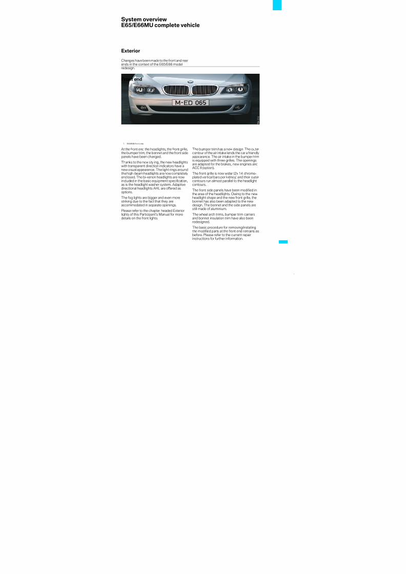
Changes havebeen madeto the front and rearends in the context of the E65/E66 modelredesign.
Front end
At the front end the headlights, the front grille,the bumper trim, the bonnet and the front sidepanels have been changed.
Thanks to the new styling, the new headlightswith transparent direction indicators have anew visual appearance. The light rings aroundthe high-beam headlights are now completelyenclosed. The bi-xenon headlights are nowincluded in the basic equipment specification,as is the headlight washer system. Adaptivedirectional headlights AHL are offered asoptions.
The fog lights are bigger and even more
striking due to the fact that they areaccommodated in separate openings.
Please refer to the chapter headed Exteriorlights of this Participant's Manual for moredetails on the front lights.
The bumper trim has a new design. The outercontour of the air intake lends the car a friendlyappearance. The air intake in the bumper trimis equipped with three grilles. The openingsare adapted for the brakes, new engines andACC II (option).
The front grille is now wider (2x 14 chrome-plated vertical bars per kidney) and their outercontours run almost parallel to the headlightcontours.
The front side panels have been modified inthe area of the headlights. Owing to the newheadlight shape and the new front grille, the
bonnet has also been adapted to the newdesign. The bonnet and the side panels arestill made of aluminium.
The wheel arch trims, bumper trim carriersand bonnet insulation trim have also beenredesigned.
The basic procedure for removing/installingthe modified parts at the front end remains asbefore. Please refer to the current repairinstructions for further information.
1 - E65/E66 front view

8/3/2019 E65_66 Model Redesign
http://slidepdf.com/reader/full/e6566-model-redesign 24/101
2
Active Cruise Control ACC II is offered as an
option. The transmit/receive unit is located inthe bottom right area of the front bumper trim.
2 - Attachment parts for front bumper trim
Index Explanation Index Explanation
1 Right headlight washer system cover 7 Right grille2 Bumper trim 8 Cover for bolted towing lug
3 Left headlight washer system cover 9 Right fog light trim
4 Left fog light trim 10 Front right rubbing strip withchrome strip and locator for twoPDC sensors
5 Left grille 11 Number plate baseplate
6 Middle grille 12 Front left rubbing strip withchrome strip and locator for twoPDC sensors
3 - ACC II transmit-receive unit

8/3/2019 E65_66 Model Redesign
http://slidepdf.com/reader/full/e6566-model-redesign 25/101
3
Rear end
Rear lights
Thenewly designed rear lightswith fibre-optictechnology tail lights give the car an exclusivenight-time design with outstanding visibility.The outer contours of the rear lights in the sidepanels have stayed the same. The rear sidepanels have not been changed.
Bumper trim
The bumper trim has also been redesigned.Theside rubbing strips areslightly shorter andno longer stretch to the wheel apertures.
On cars fitted with the trailer tow hitch optionthe bumper trim is cut out accordingly at thebottom and sealed with a cover.
The exhaust tailpipes are covered by thebumper trim.
Boot lid
The design features of the boot lid have alsobeen altered.
The three-part light surround has beenreplaced by two larger-sized rear lights whichmerge almostseamlessly into therear lights inthe side panels.
Other new features next to the BMW badgewith chrome frame are the country-specificnumber plate trim and the long chrome stripwhich visually connects the reversing lights to
each other. In addition, the new number platelights and the new boot lid lock are integratedin the boot lid.
The boot lid trim panel is adapted to the newboot lid. The bulbs in the rear fog/reversinglights can be easily replaced by unclipping thecorresponding trim panels. The boot lid lock islocated to the right of the number plate lightand is not longer directly visible.
4 - E65/E66 rear view

8/3/2019 E65_66 Model Redesign
http://slidepdf.com/reader/full/e6566-model-redesign 26/101
4
All three rubbing strips and the impactabsorber can be removed from the outside.
The points at which the bumper trim isconnected to the body have not changed (redarrows).
Structural changes to the front and rearbumper trims have increased the length of thecar by 10 mm. Thus the new length is5039 mm for the E65 and 5179 mm for theE66.
5 - Attachment parts for rear bumper trim
Index Explanation Index Explanation
1 Rear bumper trim 4 Rear middle rubbing strip withchrome strip and locators for fourPDC sensors
2 Rear right rubbing strip withchrome strip
5 Impact absorber
3 Cover for bolted towing lug 6 Rear right rubbing strip withchrome strip

8/3/2019 E65_66 Model Redesign
http://slidepdf.com/reader/full/e6566-model-redesign 27/101
5
Interior
Theinterior is noweven more harmonious andhigh-quality thanks to the use of newmaterials, colours and surfaces.
For example, all the trims and the fresh-airgrilles which are in the immediatefield of visionof the occupants are coated with superior-quality paint (titanium instead of dark silver).
The headliner trims are coated with structuralsoft paint in the corresponding headlinercolour (beige, black or stone-grey).
The decorative trims now also come in new,superior-quality wood designs. "Americanwalnut" replaces "black cherry" in the basicequipment specification. The fine wooddesign light or dark "variegated ash" is
available as an option.Many individual parts such as e.g. lockingknobs, inside door handles, frames of drinksholders etc. are modelled in pearl-effectchrome.
6 - New materials and surfaces enhance the superior-quality appearance of the interior

8/3/2019 E65_66 Model Redesign
http://slidepdf.com/reader/full/e6566-model-redesign 28/101
6
Controller
The increase in quality can also be seen fromthe example of the controller. The controllerhas a new shape and is made from a newmaterial. It is designed in a so-calledmonosandwich with leather insert. The leatherinsert has a practical as well as a visual benefitfor the customer in that it is equally pleasant totouchwhen hotor cold.Thecontroller trim hasa new shiny finish thanks to the titanium paint.
Steering wheel
The design of the steering wheel has alsobeen changed. The airbag impact pad nowhas slightly curved edges at the top andbottom. The steering wheel comes in thesame colour as the instrument panel trim.
7 - New controller
Index Explanation
1 Leather insert
2 Controller in pearl-effectchrome
3 Titanium-painted controller trim
8 - Comparison of steering wheel design

8/3/2019 E65_66 Model Redesign
http://slidepdf.com/reader/full/e6566-model-redesign 29/101
7
IHKA controls and light switch centre
The IHKA controls and the light switch centrehave been visually enhanced. The rotaryknobs are modelled in pearl-effect chrome.
The buttons or the button groups and therotary knobs are set off by a so-called insulardesign. The corresponding trims are coatedwith high-quality paint (titanium).
The OFF button and defrost button havechanged places.
9 - Controls for High automatic climate control
Index Explanation Index Explanation
1 Switch off automatic climatecontrol (new position)
2 Left interior air supply controllerand defrost button (new position)

8/3/2019 E65_66 Model Redesign
http://slidepdf.com/reader/full/e6566-model-redesign 30/101
8

8/3/2019 E65_66 Model Redesign
http://slidepdf.com/reader/full/e6566-model-redesign 31/101
9
Service informationE65/E66MU complete vehicle
Conversion
The previously manufactured E65/E66 carscan be converted to the new visual design.
For this purpose, the following conversion kitsare offered, depending on options, steering,short or long version and engine.
Body kits
1 - Overview of conversion parts
Left-hand drive/right-
hand drive
Equipment Kit number (as at 11/2004)
LHD Bi-xenon, without PDC 0 032 849
LHD Bi-xenon, with PDC 0 032 850
LHD Bi-xenon, with AHL, withoutPDC
0 032 851
LHD Bi-xenon, with AHL, with PDC 0 032 852
RHD Bi-xenon, without PDC 0 032 853
RHD Bi-xenon, with PDC 0 032 854
RHD Bi-xenon, with AHL, withoutPDC
0 032 855
RHD Bi-xenon, with AHL, with PDC 0 032 856

8/3/2019 E65_66 Model Redesign
http://slidepdf.com/reader/full/e6566-model-redesign 32/101
10
The body kit contains e.g. both bumper trimsincl. attachment parts, headlights, front foglights, rear light cluster, bonnet, boot lid, frontside panels etc.
Sill trims are available for the short and longversions:
• E65, kit number: 0 032 857
• E66, kit number: 0 032 858.
Radiator kits
Restrictions
No conversion kits are offered for cars withOption 235 Trailer tow hitch. Nevertheless,the customer will still be able to convert theircar by:
• Deciding to purchase a new trailer towhitch, or
• Foregoing trailer towing.
Likewise no conversion kits are offered forcars with Option 541 Active cruise control, asACC II is not backwards-compatible.
Cars in the US national-market specification
cannot be converted either!
The offer is only applicable to E65/E66 carswith the following engines:
• M57
• M67
• N62
• N73
Only white direction indicators areoffered on aworldwide basis.
The conversion kits are suitable for Basic andChromeline.
3 No conversion kits are offered for the carinterior. 1
Engine Kit number
N62 0 395 754
N73 0 395 755
M67 0 395 756

8/3/2019 E65_66 Model Redesign
http://slidepdf.com/reader/full/e6566-model-redesign 33/101
ContentsE65/E66MU drive
System components 1
N52 engine 1
N62TU engine 2
M57D30TU2 engine 8
Transmission 11

8/3/2019 E65_66 Model Redesign
http://slidepdf.com/reader/full/e6566-model-redesign 34/101

8/3/2019 E65_66 Model Redesign
http://slidepdf.com/reader/full/e6566-model-redesign 35/101
1
System componentsE65/E66MU drive
N52 engine
The M54B30 engine is replaced by theN52B30 engine.
The N52B30 engine is known from theE63/64 model series. The following areas areadapted vehicle-specifically:
• Programming of Digital Motor Electronics(DME).
• Air intake duct in the car.
Technical data/history
The N52B30 engine is used in the following model series:
1 - N52B30 full-load diagram
Series/Model Engine kW/bhpat rpm
Nmat rpm
Exhaustemission
stage
Enginecontrol
E60/530i N52B30 190/2586600
3002500 - 4000
EURO 4 MSV 70
E61/530i N52B30 190/2586600
3002500 - 4000
EURO 4 MSV 70
E63/630i N52B30 190/2586600
3002500 - 4000
EURO 4 MSV 70
E64/630i N52B30 190/2586600
3002500 - 4000
EURO 4 MSV 70
E90/330i N52B30 190/2586600
3002500 - 4000
EURO 4 MSV 70
E65MU/730i N52B30 190/2586600
3002500 - 4000
EURO 4 MSV 70

8/3/2019 E65_66 Model Redesign
http://slidepdf.com/reader/full/e6566-model-redesign 36/101
2
N62TU engine
The N62 engine is replaced by the N62TUengine. The N62TU engine features changesfrom its predecessor in the following areas:
• Air intake duct
• Differentiated intake system (DISA)
• Crankshaft
• Oil dipstick
• Oil pump
• Inlet and exhaust valves
• Spark plugs
• DME 9.2.2
The secondary-air system is only used in theUS market.
Technical data/historyThe N62 engine is used in the following model series:
Series/Model
Engine kW/bhpat rpm
Nmat rpm
Exhaustemissionstage
Enginemanagement
E65/735i
N62B36 200/2726200
3603700
EURO 4LEV II
ME 9.2+ VALVETRONICECU
E65/745i
N62B44 245/3336100
4503600
EURO 4LEV II
ME 9.2+ VALVETRONICECU
E60/545i
N62B44 245/3336100
4503600
EURO 4ULEV II
ME 9.2.1+ VALVETRONICECU
E63/645i
N62B44 245/3336100
4503600
EURO 4ULEV II
ME 9.2.1+ VALVETRONICECU
E64/645Ci
N62B44 245/3336100
4503600
EURO 4ULEV II
ME 9.2.1+ VALVETRONICECU
E53/X5 4.4i
N62B44 235/3206100
4403700
EURO 4LEV II
ME 9.2.1+ VALVETRONICECU
E53/X5 4.8i
N62B48TU 265/3606200
4903400
EURO 3LEV/MDV
ME 9.2.+ VALVETRONICECU
E65MU/740i
N62B40TU 225/3066300
3903500
EURO 4ULEV II
ME 9.2.2+ VALVETRONICECU
E65MU/750i
N62B48TU 270/3676300
4903400
EURO 4ULEV II
ME 9.2.2+ VALVETRONICECU

8/3/2019 E65_66 Model Redesign
http://slidepdf.com/reader/full/e6566-model-redesign 37/101
3
Air intake duct
The N62B48TU engine has a greaterdisplacement and thus a higher air throughput
rate than the N62B40TU engine. A larger,two-channel air intake duct is therefore used
in the N62B48TU engine. The N62B40TUengine retains the single-channel air intake
duct with an air filter.
2 - N62B40TU full-load diagram 3 - N62B48TU full-load diagram
4 - N62B48TU air intake duct
Index Explanation Index Explanation
1 Raw air intake 3 Hot-film air-mass meter (HFM)
2 Intake silencer 4 Clean air flow to intake system
8/3/2019 E65_66 Model Redesign
http://slidepdf.com/reader/full/e6566-model-redesign 38/101
4
Differentiated intake system (DISA)
The previous fully variable intake system(DISA) is no longer used in the N62B40TU
and N62B48TU engines. A two-stage intakesystem (DISA) is used instead.
5 - Differentiated intakesystem (DISA)
Index Explanation Index Explanation
1 Servomotor, cylinder bank 1 3 Servomotor, cylinder bank 2
2 Differential pressure sensor 4 Bores for fuel injectors
8/3/2019 E65_66 Model Redesign
http://slidepdf.com/reader/full/e6566-model-redesign 39/101
5
Functional principle
In the intake system a sliding sleeve (3) islocated at the intake manifold for eachcylinder. The displacement of the sleevesdetermines whether the intake passage islong (1) or short (2).
At idle a long intake passage is set (torquesetting).
From 4700 rpm (N62B48TU) or 4800 rpm(N62B40TU)thesleeves arepushedback anda short intake passage is thereby set (powersetting). When there is no flow, the slidingsleeves remain in their respective position.
Varying the intake passages controls thepressure wave in the intake manifold in such away as to produce a boost effect in the highrpm range.
The sliding sleeves aredrivenby a servomotorassigned to each cylinder bank. The two
6 - Sectional view of intakesystem. The intakepassages are shown byarrows.
Index Explanation Index Explanation
1 Long intake passage 3 Direction of movement of sliding
sleeves2 Short intake passage
7 - Sliding sleeves closed = torque setting
8 - Sliding sleeves open = power setting

8/3/2019 E65_66 Model Redesign
http://slidepdf.com/reader/full/e6566-model-redesign 40/101
6
servomotors together with the differentialpressure sensor form a single component.
The 12V servomotors are actuated by theDDE via a PWM signal. While the slidingsleeves are open (power setting), theservomotors are actuated with a 5 % PWMsignal in order to hold the sleeves in their openposition. The servomotors do not haveposition feedback. The sleeves can beinspected visually through the throttle valve
opening. The sleeves are opened and closedonce when the ignition is turned on. Thisprevents the sleeves from seizing duringextended operation in the torque setting.
The bores for the fuel injectors and theconnections for crankcase and tankventilationare located on the intake system (DISA). Theintake system is made of glass-fibre-reinforced plastic.
Crankshaft
The N62B40TU engine has a cast crankshaft;due to the increased demands, theN62B48TU engine has a steel crankshaft. Inthe interests of reducing power loss (oil
churning losses in the crankcase), thecrankpin width has been reduced from42 mmto 36 mm. The connecting rods are adaptedaccordingly.
Oil pump
The geometry of the oil pump is vehicle-specifically adapted. Oil churning losses in the
crankcaseare further reduced by themodifieddesign of the oil deflector.
Oil dipstick
The E65 Facelift model series is equippedwith an electronic oil level display. Thedipstickhas a modified handle in black.
This eliminates the need for the customer tocheck the engine oil level twice.
Inlet and exhaust valves
The stem diameter has been reduced from6 mm to 5 mm. The moving masses reduced
in this way result in a higher maximum numberof revs.
Spark plugs
The previous surface-gap spark plugs with 2
ground electrodes have been replaced byspark plugs with the spark position broughtforward and a hook electrode.
This enables better ignition of the fuel/air
mixture. In the new spark plugs the centreelectrode is made of platinum (replacementinterval: every 100,000 km).

8/3/2019 E65_66 Model Redesign
http://slidepdf.com/reader/full/e6566-model-redesign 41/101
7
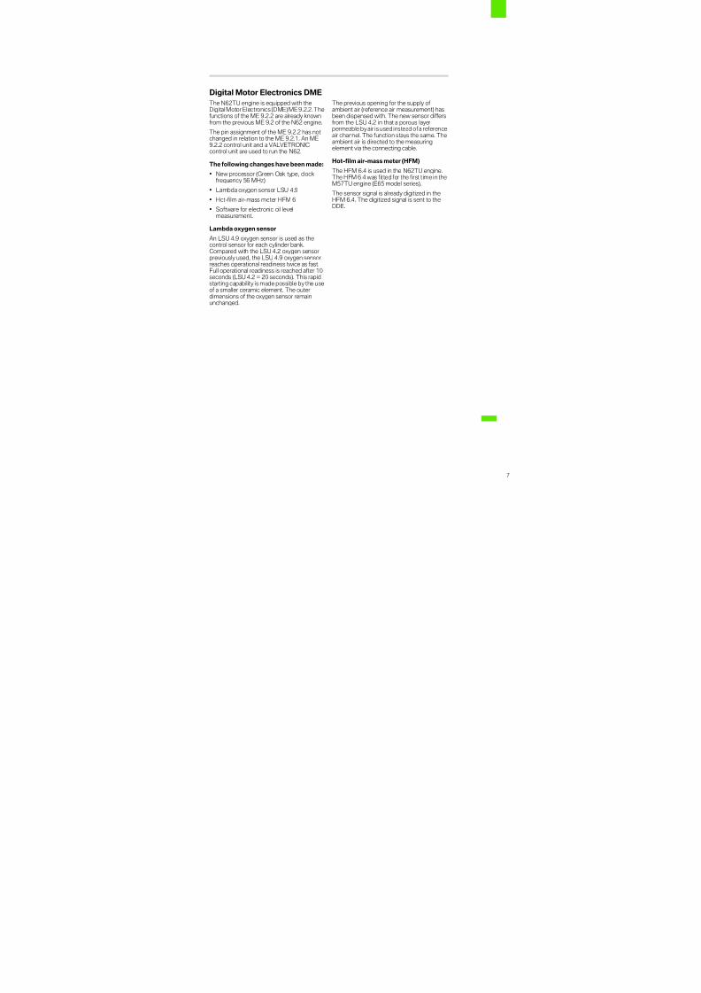
Digital Motor Electronics DME
The N62TU engine is equipped with theDigital Motor Electronics (DME) ME9.2.2.Thefunctions of the ME 9.2.2 are already knownfrom the previous ME 9.2 of the N62 engine.
The pin assignment of the ME 9.2.2 has notchanged in relation to the ME 9.2.1. An ME9.2.2 control unit and a VALVETRONICcontrol unit are used to run the N62.
The following changes have been made:
• New processor (Green Oak type, clockfrequency 56 MHz)
• Lambda oxygen sensor LSU 4.9
• Hot-film air-mass meter HFM 6
• Software for electronic oil levelmeasurement.
Lambda oxygen sensor
An LSU 4.9 oxygen sensor is used as thecontrol sensor for each cylinder bank.Compared with the LSU 4.2 oxygen sensor
previously used, the LSU 4.9 oxygen sensorreaches operational readiness twice as fast.Full operational readiness is reached after 10seconds (LSU 4.2 = 20 seconds). This rapidstarting capability is made possible by the useof a smaller ceramic element. The outerdimensions of the oxygen sensor remainunchanged.
The previous opening for the supply of ambient air (reference air measurement) hasbeen dispensed with. The new sensor differsfrom the LSU 4.2 in that a porous layerpermeable by air is used instead ofa referenceair channel. The function stays the same. Theambient air is directed to the measuringelement via the connecting cable.
Hot-film air-mass meter (HFM)
The HFM 6.4 is used in the N62TU engine.The HFM 6.4 was fitted for the first time in theM57TU engine (E65 model series).
The sensor signal is already digitized in theHFM 6.4. The digitized signal is sent to theDDE.

8/3/2019 E65_66 Model Redesign
http://slidepdf.com/reader/full/e6566-model-redesign 42/101
8
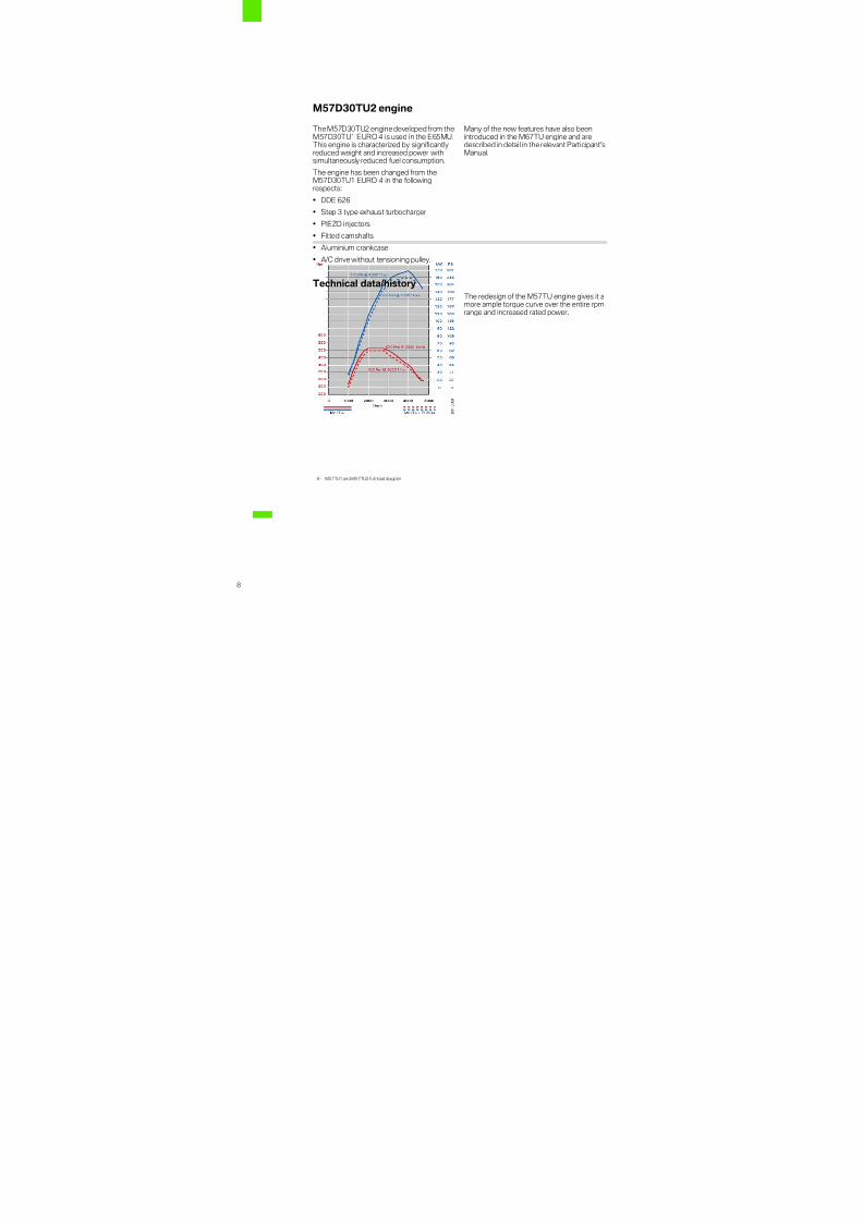
M57D30TU2 engine
The M57D30TU2 engine developed from theM57D30TU1 EURO 4 is used in the E65MU.This engine is characterized by significantlyreduced weight and increased power withsimultaneously reduced fuel consumption.
The engine has been changed from theM57D30TU1 EURO 4 in the followingrespects:
• DDE 626
• Step 3 type exhaust turbocharger• PIEZO injectors
• Fitted camshafts
• Aluminium crankcase
• A/C drive without tensioning pulley.
Many of the new features have also beenintroduced in the M67TU engine and aredescribed in detail in the relevant Participant'sManual.
Technical data/history
The redesign of the M57TU engine gives it amore ample torque curve over the entire rpmrange and increased rated power.
9 - M57TU1 and M57TU2 full-load diagram

8/3/2019 E65_66 Model Redesign
http://slidepdf.com/reader/full/e6566-model-redesign 43/101
9
The M57D30 engine from TU1 is used in the following model series:
Digital Diesel Electronics (DDE)
DDE 626 is used, offering additional functionsfor PIEZO injectors
and electronic oil level measurement.
Exhaust turbocharger
The turbocharger belongs to the thirddevelopment stage - Step 3 type. It featureselectrical adjustment of the guide vanes.
Efficiency is further improved throughoptimization of the thermodynamics and theelectric actuator.
Fuel injectorsThe M57TU2 is now equipped with PIEZOinjectors instead of SV injectors. Because of their fast needle movements and shortswitching times, PIEZO injectors are ideallysuited for multiple injections. They are alsolighter and more compact and have a low
power demand. In all, they improve fuelconsumption, pollutant emissions andacoustics.
Their function and design are described indetail in the M67TU.
Cylinder head
The valve diameters have been increased andthe intake ducts adapted accordingly.
Series/Model
Engine kW/bhpat rpm
Nmat rpm
Exhaustemissionstage
Enginemanagement
E46/330d
M57D30TU1 150/2044000
4101500-3250
EURO 3 DDE 5.0
E46/330d
M57D30TU1 150/2044000
4101500-3250
EURO 4 DDE 506
E83/X3 3.0d
M57D30TU1 150/2044000
4101500-3250
EURO 3 DDE 506
E53/
X5 3.0d
M57D30TU1 160/218
4000
500
2000-2750
EURO 3 DDE 506
E65/730d
M57D30TU1 160/2184000
5002000-2750
EURO 3 DDE 506
E60/530d
M57D30TU1 160/2184000
5002000-2750
EURO 3 DDE 508
E60/530d
M57D30TU1EURO 4
160/2184000
5002000-2750
EURO 4 DDE 509
E60/535d
M57D30TU1TOP
200/2724400
5602000-2250
EURO 4 DDE 606
E65MU/730d
M57D30TU2 170/2314000
5202000-2750
EURO 4 DDE 626

8/3/2019 E65_66 Model Redesign
http://slidepdf.com/reader/full/e6566-model-redesign 44/101
10
Camshaft
Fitted camshafts are now used, as is alreadythe case in the M57D25TU1 engine. Thesecamshaft offer advantages with regard toweight and manufacturing possibilities. Hererecourse is had to the construction kit and theidentical part from the M57D25TU1 engine isused.
Fitted means that the individual parts aremanufactured separately and then installedtogether. The procedure is the same as thatfortheM67TUand is describedin closerdetailthere.
Crankcase
The crankcase is manufactured from a chilledaluminium casting and has thermally joinedcast iron bushes. This reduces the weight by20 kg. The main bearing caps are made of sintered metal. A moulding on the contact
surface to the crankcase enables significantlyhigher transverse forces to be transmitted.The bearing cap is thereby also precision-positioned in the longitudinal and transversaldirections.
Oil level measurement
The E65MU is equipped with an electronic oillevel display. The oil dipstick has an
inconspicuous black handle because it is onlyintended for Service.
Belt drive
The A/C drive has an elasti-belt, thuseliminating the need for a tensioning pulley.

8/3/2019 E65_66 Model Redesign
http://slidepdf.com/reader/full/e6566-model-redesign 45/101
11
Transmission
Automatic transmissions
The GA6HP19/26/32Z automatictransmissions have been optimized for all themodel series in the following respects:
• New linings on the shift clutches
• Use of new fine filters in the hydraulicsystem
• Newly designed converter connection
The newly designed transmission control unitGS 19.11 is used for the automatictransmissions. Compared to its predecessor(GS 19.04) it offers the following advantages:
• New processor with higher computingcapacity and flash memory expanded from512 KB to 1 MB
• Designed to withstand higher temperatures
• Electromagnetic compatibility considerablyimproved
• Reserve for further functions
• Optimization of shift quality, shifting timeand hysteresis tuning.
The control unit is located on themechatronics module in thetransmission. Thehousing and the pin assignments have notbeen changed.
Rear differential
The gear ratio of the rear differential has beenadapted to the modified engine variants:
• N52B30engine: differential 215 K (i = 4.10)
• M67TU engine: differential 230 K (i = 2.92).

8/3/2019 E65_66 Model Redesign
http://slidepdf.com/reader/full/e6566-model-redesign 46/101
12

8/3/2019 E65_66 Model Redesign
http://slidepdf.com/reader/full/e6566-model-redesign 47/101
ContentsE65/E66MUbus overview
System overview 1
Bus overview 1
Vehicle electrical system changes 4

8/3/2019 E65_66 Model Redesign
http://slidepdf.com/reader/full/e6566-model-redesign 48/101

8/3/2019 E65_66 Model Redesign
http://slidepdf.com/reader/full/e6566-model-redesign 49/101
1
System overviewE65/E66MU bus overview
Bus overview
1 - E65/E66 bus systems
8/3/2019 E65_66 Model Redesign
http://slidepdf.com/reader/full/e6566-model-redesign 50/101
2
Index Explanation Index Explanation
WUP Wake-up line DVD Digital Versatile Disc
CAS Car Access System VM Video Module
HKL Boot lid lift NAV Navigation system
TMFAT Door module, driver's side SVS Voice recognition system
TMFAH Door module, driver's side, rear KHI Headphones interface
SMFA Seat module, driver AVT Aerial amplifier
SMFAH Seat module, driver's side, rear CDC Compact Disc Changer
PGS Passive-Go control unit SGM Safety and Gateway Module
SMBFH Seat module, passenger side,
rear
SZL Steering column switch cluster
SMBF Seat module, passenger SASL A-pillar satellite, left
TMBFH Door module, passenger side,rear
STVL Door satellite, front left
TMBFT Door module, passenger door SSFA Driver's seat satellite
PM Power Module SBSL B-pillar satellite, left
AHM Trailer module SSH Rear seat satellite
PDC Park distance control SBSR B-pillar satellite, right
FKA Rear-compartment airconditioning
SSBF Passenger seat satellite
CIM Chassis Integration Module STVR Door satellite, front rightEHC Electronic ride-height control SASR A-pillar satellite, right
DWA Anti-theft alarm system SFZ Satellite, vehicle centre
IHKA Integrated automatic heater andclimate control
DME Digital Motor Electronics
ZH Auxiliary heater DDE Digital Diesel Electronics
FD Rear-compartment display DME2 Digital Motor Electronics 2
LM Light Module EDC-K Continuous Electronic DamperControl
WIM Wiper module ACC II Active Cruise Control II
BZMF Switch cluster, centre armrest,
rear
ARS Dynamic Drive
FCON Rear-compartment controller EGS Electronic transmission control
SH Independent heating DSC Dynamic Stability Control
SHD Slide/tilt sunroof GRS Yaw rate sensor
RLS Rain and Light Sensor EMF Parking brake
BZM Centre console switch cluster D-Bus Diagnosis bus
CON Controller K-CAN P Body CAN peripherals
CD Control Display K-CAN S Body CAN system
SG FD Control unit, rear-compartmentdisplay
MOST Media Oriented System Transport
I-KOMBI Instrument cluster byteflight byteflight FS Flash connector PT-CAN Powertrain CAN
ASK Audio system controller K-Bus Body bus (protocol)
8/3/2019 E65_66 Model Redesign
http://slidepdf.com/reader/full/e6566-model-redesign 51/101
3
LOGIC7 Top-HiFi amplifier BSD Bit-serial data interface
SDARS Satellite radio CAN CAN (protocol)
TEL Telephone LoCAN Local Controller Area Network
Index Explanation Index Explanation
8/3/2019 E65_66 Model Redesign
http://slidepdf.com/reader/full/e6566-model-redesign 52/101
4
Vehicle electrical system changes
Changes in the E65/E66 bus diagram in 03/2005
Adaptive directional headlights and lightmodule
When adaptive directional headlights wereintroduced, it was necessary to connect theAHL control unit to the PT-CAN.The AHL control unit will be dispensed with in03/2005 because this function is to be taken
over by the LM light module. The light modulereceives the information from the PT-CAN(yaw rate, road speed and steering angle) via adirect PT-CAN connection.
The LM light module has a direct connectionto the PT-CAN only in cars with the Adaptivedirection headlights option.
ZH auxiliary heater
When diesel engines were introduced, it wasnecessary to extend the system to include aZH auxiliary heater control unit.
MOST
The KHI headphones interface KHI andLOGIC7 control units have changed places inthe MOST ring.
VM
The new Hybrid video module or Hybrid Drive
video module is used in the EU version. Thedesignation VM Video Module is now thegeneric term for all video modules:
• Hybrid video module (CVBS)
• Hybrid Drive video module (CVBS/RGB)
• Video module 5 (RGB)
• Drive video module 5 (CVBS).
PT-CAN
Active Cruise Control II ACC II is used insteadof Active Cruise Control ACC.
Changes in the E65/E66 bus diagram since 03/2004
There have already been some changes in thebus structure on account of the changes in theISIS in 03/2004.
These changes in particular are:
K-CAN S
Dropping of the RDC control unit (tyrepressure control) because this function istaken over by the Run Flat Indicator software
in the DSC. In the E67 the RDC continues tobe used as a control unit because of the PAXtyres.
Dropping of the KHA module (headphonesconnection) as a control unit on the K-CAN.The jacks of the headphone connections forrear-compartment entertainment areconnected directly to the KHI (headphonesinterface).
MOST
Extension of the MOST rings to include theSDARS control unit (Satellite Digital AudioRadio Services)because this systemis used inUS vehicles in 03/2004.
byteflight
The satellites are connected directly to theSGM (Safety and Gateway Module) throughintegration of the SIM in the gateway module.The star structure of the byteflight has beenretained. The SGM serves as the gateway forthe entire bus systems.
PT-CAN
The PT-CAN has been extended to includethe following systems:
DDE (Digital Diesel Electronics)
Use of the DDE on the PT-CAN was deemednecessary when diesel engines wereintroduced. The LoCAN engine bus is notrequired at the DDE control unit (no VVT).
DME2 (Digital Motor Electronics)
A second DME control unit on the PT-CANwas deemed necessary when the 12-cylinderengine was introduced in the 760i/iL.

8/3/2019 E65_66 Model Redesign
http://slidepdf.com/reader/full/e6566-model-redesign 53/101
ContentsE65/E66MUenergy management
System overview 1
System circuit diagram 1
Functions 3
Changes in energy management 3
Summary 9
Points to remember 9

8/3/2019 E65_66 Model Redesign
http://slidepdf.com/reader/full/e6566-model-redesign 54/101

8/3/2019 E65_66 Model Redesign
http://slidepdf.com/reader/full/e6566-model-redesign 55/101
1
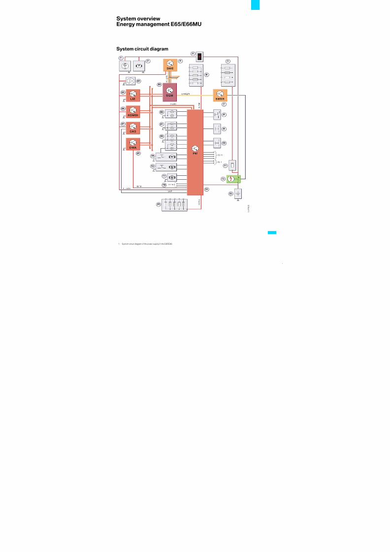
System overviewEnergy management E65/E66MU
System circuit diagram
1 - System circuit diagram of the power supply in the E65/E66

8/3/2019 E65_66 Model Redesign
http://slidepdf.com/reader/full/e6566-model-redesign 56/101
2
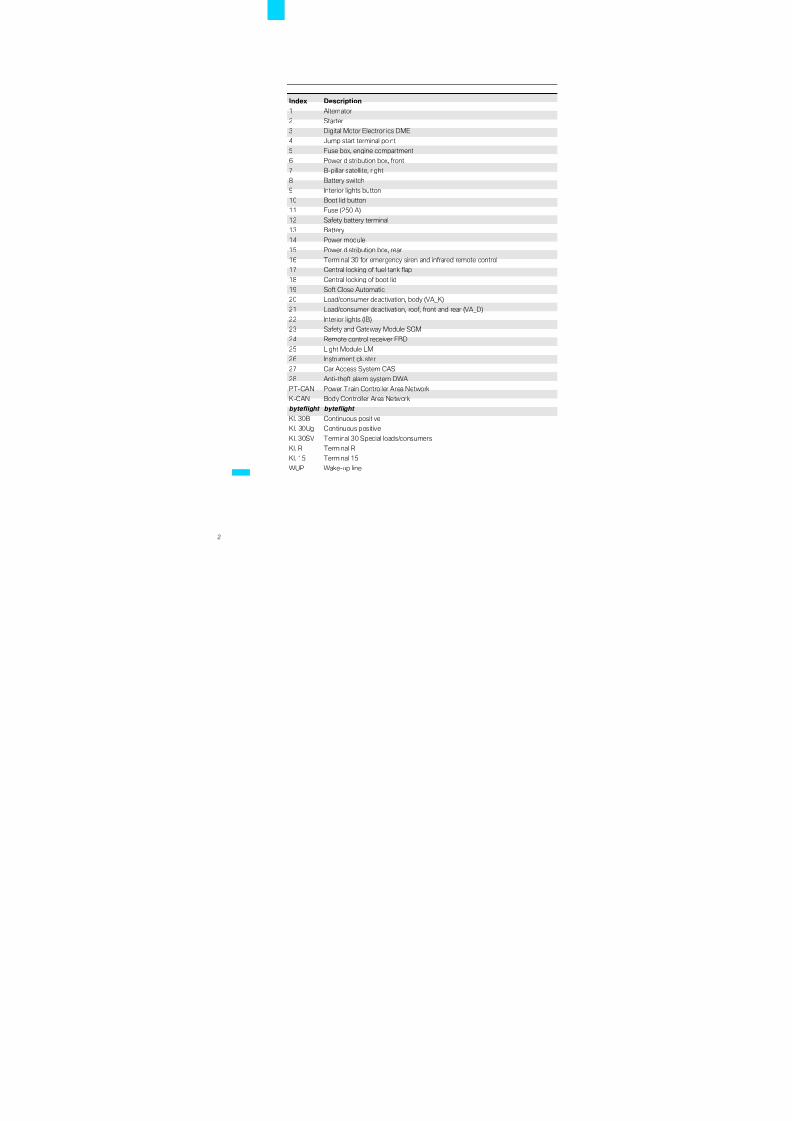
Index Description
1 Alternator
2 Starter
3 Digital Motor Electronics DME
4 Jump start terminal point
5 Fuse box, engine compartment
6 Power distribution box, front
7 B-pillar satellite, right
8 Battery switch
9 Interior lights button
10 Boot lid button
11 Fuse (250 A)
12 Safety battery terminal
13 Battery
14 Power module
15 Power distribution box, rear
16 Terminal 30 for emergency siren and infrared remote control
17 Central locking of fuel tank flap
18 Central locking of boot lid
19 Soft Close Automatic
20 Load/consumer deactivation, body (VA_K)
21 Load/consumer deactivation, roof, front and rear (VA_D)
22 Interior lights (IB)
23 Safety and Gateway Module SGM
24 Remote control receiver FBD
25 Light Module LM
26 Instrument cluster
27 Car Access System CAS
28 Anti-theft alarm system DWA
PT-CAN Power Train Controller Area Network
K-CAN Body Controller Area Network
byteflight byteflight
Kl. 30B Continuous positive
Kl. 30Ug Continuous positive
Kl. 30SV Terminal 30 Special loads/consumers
Kl. R Terminal R
Kl. 15 Terminal 15
WUP Wake-up line

8/3/2019 E65_66 Model Redesign
http://slidepdf.com/reader/full/e6566-model-redesign 57/101
3
FunctionsEnergy management E65/E66MU
Changes in energy management
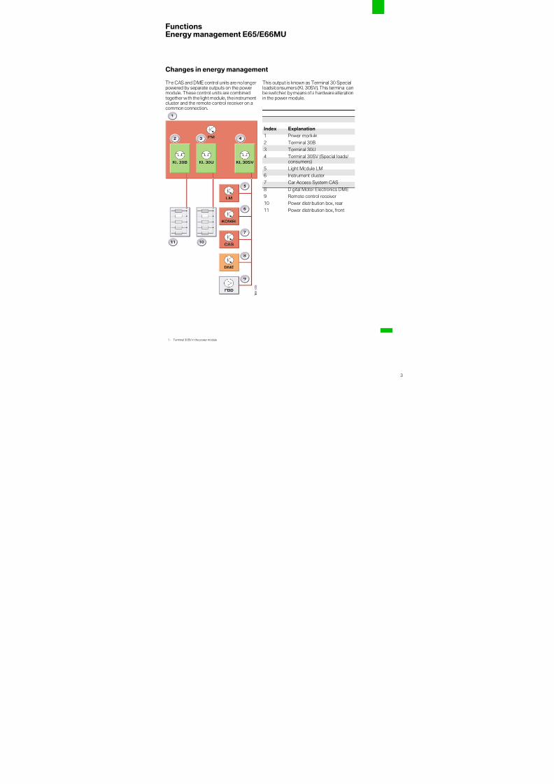
The CAS and DME control units are no longerpowered by separate outputs on the powermodule. These control units are combinedtogether with the light module, the instrumentcluster and the remote control receiver on acommon connection.
This output is known as Terminal 30 Specialloads/consumers (Kl. 30SV). This terminalcanbe switched by means of a hardware alterationin the power module.
1 - Terminal 30SV in the power module
Index Explanation
1 Power module2 Terminal 30B
3 Terminal 30U
4 Terminal 30SV (Special loads/consumers)
5 Light Module LM
6 Instrument cluster
7 Car Access System CAS
8 Digital Motor Electronics DME
9 Remote control receiver
10 Power distribution box, rear
11 Power distribution box, front

8/3/2019 E65_66 Model Redesign
http://slidepdf.com/reader/full/e6566-model-redesign 58/101
4
New deactivation strategy
In the previous concept of power moduledeactivation, only the path of terminal 30loads/consumers (term. 30B and term. 30U)was de-energized in the event of a closed-circuit current fault. Only the current atterm. 30U and term. 30B was evaluated todetect this fault.
What is new is that terminal 30SV can nowalso be switched. However currentmeasurement is not possible at terminal
30SV. Increased closed-circuit currentconsumption is detected indirectly bymonitoring bus communicationon theK-CAN.
If bus communication is present withoutreason, terminal 30SV is briefly disconnectedfrom the power supply.
In this way it is possible to rectify possibleproblems caused by faulty software becausethecontrol units shouldswitch back into sleepmode properly after the restart. Theinformation on a problem however is stored inthe power module and the workshop cansearch for a fault in the affectedcontrol units at
terminal 30SV.Disconnection of term. 30SV is performedonly if term. 30B and term. 30U were alreadydisconnected beforehand or at the same timeand if none of the light functions (parkinglights, hazard warning system) is switched on.
3 The Digital Diesel Electronics DDEcontinues to be powered via the distributionbox in the engine compartment. 1
Deactivation strategy in event of excessive closed-circuit current
1. Reset of terminal30U and terminal30B inevent of violation of the closed-circuitcurrent threshold (as previously)
2. Disconnection of terminal 30U andterminal 30B in eventof renewedviolationof the closed-circuit current threshold (aspreviously)
3. Reset of terminal 30SV for 10 seconds(new) if the bus users on the K-CAN (PM,CAS, LM, instrument cluster, DWA) havenot gone to sleep within 5 minutes of terminals 30U and 30B beingdisconnected.
The "Term. 30SV reset" procedure is carriedout only once within a closed-circuit currentmonitoring phase as this action causes theentire vehicle electrical system to be cut in(high current consumption).
Deactivation strategy in event of toomany wake-up operations
1. Disconnection of terminal 30U andterminal 30B if the wake-up counter
threshold is reached, currently 30 wake-up operations
2. Reset of terminal 30SV for 10 seconds(new) if the bus users on the K-CAN (PM,CAS, LM, instrument cluster, DWA) havenot gone to sleep within 5 minutes of terminals 30U and 30B beingdisconnected.
3 The connected control units are notoperational during the period whenterm. 30SV is deactivated. The car cannot beunlocked with the remote control during thisphase.
It is still possible to open the car door with themechanical key, but this results in an alarmbeing triggered if a movement in thepassenger compartment is detected as theanti-theft alarm system is still armed andresponds as if for example a window has beenbroken. The anti-theft alarm system isdeactivated by inserting the ID sensor in theCAS slot, whereby disarming is signalled tothe anti-theft alarm system if the vehicleelectrical system is activated. 1
3 The instrument cluster retains thedata onaccount of the brief disconnection(10 seconds). Only the clock is slow by thecorresponding time. 1

8/3/2019 E65_66 Model Redesign
http://slidepdf.com/reader/full/e6566-model-redesign 59/101
5
Normal sleep procedure without closed-circuit current violation
In a "normal" car sleep procedure, the CANbus goes to sleep a few minutes after"terminal R OFF". After 16 minutes the PMsends the signal to deactivate the loads/consumers and the bus is woken up briefly inthe process. The "VA_Roof" driver isdeactivated and the CAN bus goes to sleepagain. After 60 minutes have elapsed (codablevalue if no telephone/EGS logs in as a load/consumer in stationary mode 16 minutes) the"VA_Body" driver is also deactivated, by
means of which a current of approx. 200 mAfor relay activation for VA_K is likewiseomitted. The power module then goes intoclosed-circuit current monitoring mode.
Detection of a closed-circuit currentviolation
During closed-circuit current monitoring thepower module measures the voltage valueevery 5 seconds and the current value every60 seconds. The power module goes intoincreased closed-circuit monitoring mode inthe event of a closed-circuit current violation
(I > 80 mA). Here the power moduledetermines the present current value every1.5 seconds over a waiting period of 8minutes. During this period the vehicle
electrical system is given the opportunity toaccept a normal closed-circuit current again. If during the 8 minutes a current is detectedwhich is below the closed-circuit currentthreshold of 80 mA for longer than oneminute, the waiting period is started again andthe power module goes into closed-circuitcurrent monitoring mode again.
If the closed-circuit current violation persistsafter the waiting period has elapsed, theshutdown counter is started (90 seconds).Then a general reset is performed. Generalresetmeans thatall loads/consumers suppliedby the power module with the exception of terminal 30SV and the anti-theft alarm systemare disconnected from the battery for30 seconds. Then theclosed-circuit current ismonitored for a further 8 minutes. If theclosed-circuit current violation persists, theshutdown counter is started again(90 seconds). Then all the loads/consumersare deactivated (with the exception of terminal30SV and the anti-theft alarm system).
If a further closed-circuit current violation isindirectly determined via bus activity over atime period of 5 minutes, a one-off reset of terminal 30SV is performed for 10 seconds.
2 - Sleep procedure without closed-circuit current violation

8/3/2019 E65_66 Model Redesign
http://slidepdf.com/reader/full/e6566-model-redesign 60/101
6
Example: Sleep behaviour with closed-circuit current violation
3 - Sleep behaviour with closed-circuit current violation
Index Explanation
1 Terminal R "OFF"
2 After 16 minutes the PM sends the signal to deactivate the loads/consumers and thebus is woken up briefly in the process. The "VA_Roof" driver is deactivated and theCAN bus goes to sleep again.
3 After 60 minutes have elapsed (codable value if no telephone fitted 16 minutes) the"VA_Body" driver is also deactivated.The power module then goes into closed-circuit current monitoring mode.
4 Closed-circuit current violation with 500 mAThe current violation at the end of the waiting period of 8 minutes persists.
5 Entry in the fault memory with the associated current value. The CAN bus is wokenup and the shutdown counter started for 90 seconds. A general reset is performedfor 30 seconds when theshutdown counter expires. Simply theterminal 30SV driverand the power supply for the anti-theft alarm system are not disconnected.
6 The current violation at the end of the second waiting period of 8 minutes persists.The CAN bus is woken up again and the shutdown counter started again for 90seconds.
7 Term. 30U, term. 30B and all other drivers are disconnected from the battery whenthe shutdown counter expires. Sole exception: term. 30SV and the power supply forthe anti-theft alarm system are not disconnected.
8 One or more control units (LM, instrument cluster,CAS, DME) is/are active for longerthan 5 minutes.
9 Reset of terminal 30SV for 10 seconds (if no light function is active).10 Normal sleep procedure.

8/3/2019 E65_66 Model Redesign
http://slidepdf.com/reader/full/e6566-model-redesign 61/101
7
Measures for maintaining battery starting capability (SoC)
Electric loads/consumers in stationarymode
Certain loads/consumers may be active evenwhen closed-circuit current monitoring of thepower module is already running. This isnecessary for various reasons:
– Legally required electric loads, e.g. parkinglights, hazard warning system
– Convenience for the customer, e.g. radio
function, telephoneThese loads/consumers must be excludedfrom the closed-circuit monitoring system inorder to avoid misinterpretation in the powermodule. For this purpose, these loads/consumers must log in with the powermodule. In turn, the power module recognizesthe activity and accepts the higher powerconsumption. When these systems aredeactivated, the corresponding control unitslog off from the power module.
Disconnection of term. 30
In the previous concept of power moduledeactivation, terminal 30 (term. 30U andterm. 30B) was not disconnected in the caseof a car without a closed-circuit currentviolation. A slow drop in the capacity of the carbattery (SoC = state of charge) below thestarting capability limit without a discerniblereason was possible and this effect wascounteracted by no action of the powermodule.
The following function is new:When loads/consumers are logged off, acodable waiting time (currently 5 minutes)ensues from the point "terminal R OFF".Term. 30U and term. 30B are disconnectedfrom the battery when the state of chargedrops below the starting capability limit.
This disconnection is not preceded by a"general reset".
4 - Disconnection of term. 30U and term. 30B.
Index Explanation
1 Starting capability limit
2 Terminal R "OFF"
3 Disconnection of term. 30U andterm. 30B

8/3/2019 E65_66 Model Redesign
http://slidepdf.com/reader/full/e6566-model-redesign 62/101
8
Shortening of run-on time
In the previous concept of power moduledeactivation in a car with a closed-circuitcurrent fault, a further battery disconnectionon account of a closed-circuit current violation
takes place only after a run-on time of 60 minutes (16 minutes).
As a result of this long run-on time the state of battery charge could drop far below the valueof the starting capability limit without anintervention by the power module.
The improvement of the new deactivationstrategy becomes apparent with a renewedactivation of the loads/consumers (by aterminal change or unlocking of the car) in theevent of a previously ascertained closed-
circuit current violationor an extended startingcapability limit which has already beenreached.
In this case, closed-circuit current monitoringalready begins after 2 minutes (normally 60minutes). Together with the fixed waitingperiod of 8 minutes, it would therefore take amaximum of 10 minutes until the shutdown
counter is started.
The entire function of the shorteneddeactivation is codable. The shortenedrun-ontime is reset again as soon as the power
module has registered an "engine running"status once.
5 - State of battery chargedrops below the startingcapability limit
6 - State of battery chargedoes not drop below thestarting capability limit
Index Explanation
1 Extended starting capability limit
2 Starting capability limit
3 1st deactivation by power module
4 Change of terminal status or unlocking by remote control
5 2nd deactivation by power module
6 Change of terminal status or unlocking by remote control

8/3/2019 E65_66 Model Redesign
http://slidepdf.com/reader/full/e6566-model-redesign 63/101
9
SummaryE65MU energy management
Points to remember
The most important facts relating to BMW 7Series energy management are summarizedin the following table.
This list outlines the main points in conciseform and provides the opportunity of rechecking the most important facts providedin this Participant's Manual.
Points to remember for everydaytheoretical and practicalapplications.
Terminal 30SV
CAS, DME, instrument cluster, LM and FBD are powered via acommon output on the power module--> Terminal 30 Special loads/consumers (term. 30SV)
Properties of terminals
Term. 30U andterm. 30B
Term. 30SV
Closed-circuit-current-monitored,brief disconnection (reset) and permanent deactivation are possible
Bus-monitored,one-off, brief disconnection (reset) possible (approx. 10 seconds)
Shortening of run-on time
The run-on time of the terminals has been reduced in the event of apreviously ascertainedclosed-circuitcurrent violation from60 minutesto 10 minutes.

8/3/2019 E65_66 Model Redesign
http://slidepdf.com/reader/full/e6566-model-redesign 64/101
10

8/3/2019 E65_66 Model Redesign
http://slidepdf.com/reader/full/e6566-model-redesign 65/101
ContentsE65/E66MUexterior lights
System overview 1
System circuit diagram 1
System components 3
Involved components 3
Headlights 4
Rear light cluster 8

8/3/2019 E65_66 Model Redesign
http://slidepdf.com/reader/full/e6566-model-redesign 66/101

8/3/2019 E65_66 Model Redesign
http://slidepdf.com/reader/full/e6566-model-redesign 67/101
1
System overviewE65/E66MU exterior lights
System circuit diagram
Since the system circuit diagram for theexterior lights is very complex, the fold-outpage has been chosen as the means of representation.
You will find the fold-out pageat the end of thisParticipant's Manual.
Index Explanation Index Explanation
1 Additional direction indicator, left 27 Safety and gateway moduleSGM
2 Direction indicator, front left 28 Trailer module AHM
3 Stepping motors 29 Power module PM
4 Parking light, left 30 Rain/light sensor RLS
5 High beam shutter, left 31 Comfort Access CA
6 Bi-xenon high beam/low beamheadlight, left
32 Ride-height sensor, rear
7 High beam light, left 33 Direction indicator, rear right
8 Front fog light, left 34 Tail light, right 1
9 Stepping motor controller SMC foradaptive directional headlight, left
35 Brake light, right
10 Control unit for bi-xenon high beamheadlight, left
36 Rear fog light, right/brake forcedisplay, right
11 Front fog light, right 37 Tail light, right 212 High beam light, right 38 Reversing light, right
13 Bi-xenon high beam/low beamheadlight, right
39 Licence plate light, right
14 High beam shutter, right 40 Raised brake light
15 Parking light, right 41 Number plate light, left
16 Stepping motors 42 Reversing light, left
17 Direction indicator, front right 43 Tail light, left 2
18 Stepping motor controller SMC foradaptive directional headlight, right
44 Rear fog light, left/brake forcedisplay, left
19 Control unit for bi-xenon headlight, left 45 Brake light, left
20 Additional direction indicator, right 46 Tail light, left 1
21 Dynamic Stability Control DSC 47 Direction indicator, rear left
22 Digital Motor Electronics DME/Digital Diesel Electronics DDE
48 Hazard warning switch
23 Brake light switch BLS 49 Light module LM
24 Car access system 2 CAS 2 50 Light switch
25 Steering column switch, high beam/direction indicator lights
51 Ride-height sensor, front
26 Steering column switch cluster (SZL)

8/3/2019 E65_66 Model Redesign
http://slidepdf.com/reader/full/e6566-model-redesign 68/101
2

8/3/2019 E65_66 Model Redesign
http://slidepdf.com/reader/full/e6566-model-redesign 69/101
3
System componentsE65/E66MU exterior lights
Involved components
The following system components areinstalled for the exterior lighting:
• Control units
– Light module
– Power module
– Stepping motor controller
– Control unit for bi-xenon headlight
• Headlights (with parking lights/low beam/high beam and direction indicators)
• Fog lights
• Front additional direction indicators
• Rear light cluster
– Tail light
– Brake light
– Rear fog light
– Reversing light
– Direction indicator
– Raised brake light
• Lights operating unit• Steering column switch cluster
– Steering column switch, high beam/headlight flasher
– Steering column switch, directionindicator lights
• Sensors.
Control units
Light module
The LM light module contains the completefunctions for controlling the exterior lights.Cars with adaptive directional headlights nolonger have a separate AHL control unit. Thefunctions of the AHL control unit areintegrated in the LM. The housing and theplug coding of the LM are not changed. TheLM receives the information from thePT-CAN(yaw rate, road speed and steering angle) forcontrolling the adaptive directional headlightsvia its own PT-CAN connection.
Power module
The power module provides the power for thelight module (special loads/consumersterminal).
SMC
The stepping motor controller is located onthe side on the bi-xenon headlight.
The stepped motor controller controls andmonitors the movement of the steppingmotors of the adaptive directional headlightand headlight vertical aim control.
Bi-xenon control unit
The bi-xenon control unit is mounted on thebi-xenon headlight. It provides the voltagesupply and ignition voltage for the bi-xenonlamp.

8/3/2019 E65_66 Model Redesign
http://slidepdf.com/reader/full/e6566-model-redesign 70/101
4
Headlights
The E65/E66 has new headlights. Theheadlights have a new contour line and acompletely new internal design. Frontdirection indicators are only available in whiteon a worldwide basis.
The following two headlight variants are used:
• Standard equipmentwith bi-xenon headlight
• Option
with adaptive directional headlight Option524 (AHL)
The version with a halogen headlight is nolonger offered.
The points connecting the headlight to thebody have remained the same.
Bi-xenon headlights
The light for the parking light rings isgenerated by a common bulb and directed viathe fibre optics to the parking light rings.
The colour of the bulbs for the front directionindicators is silver in the EU version andorange in the US version.
1 - Bi-xenon headlights, EUversion
Index Explanation Index Explanation
1 Front direction indicator 3 Parking light rings
2 Bi-xenon high beam/low beam light 4 High beam light

8/3/2019 E65_66 Model Redesign
http://slidepdf.com/reader/full/e6566-model-redesign 71/101
5
The power specifications of the front lights inthe EU/US versions are summarized in thetable below:
2 - Bi-xenon headlights, USversion
Index Explanation Index Explanation
1 Front direction indicator 4 Parking light rings
2 Side-marker lamp 5 High beam light
3 Bi-xenon high beam/low beam light
Light Number (per car) Power [W] (per light)
Front parking light 2 10
High beam light 2 55
Bi-xenon 2 35
Front direction indicator 4 21
Additional direction indicator 2 5
Fog light 2 55
Side-marker lamp (US only) 2 5

8/3/2019 E65_66 Model Redesign
http://slidepdf.com/reader/full/e6566-model-redesign 72/101
6
3 - Design of bi-xenon headlight
Index Explanation Index Explanation
1 Adjusting screw 7 Ventilation hose
2 D1S lamp (replaceable) 8 Stepping motor controller SMC(replaceable)
3 Direction indicator (replaceable)EU version: silver bulbUS version: orange bulb
9 Bulb for parking light (replaceable)
4 Adjusting screw 10 Control unit for bi-xenon light
5 Stepping motor (replaceable) 11 Ventilation hose
6 Bulb for high beam light(replaceable)

8/3/2019 E65_66 Model Redesign
http://slidepdf.com/reader/full/e6566-model-redesign 73/101
7
Headlight washer system
From March 2005 the headlight washersystemwill be included in thebasic equipmentspecification in all E65/E66 models. The high-pressure nozzle is no longer attached to theheadlight but rather attached to the carrier of the bumper trim. The nozzle is aligned in such
a way that only the lens in the area of the lowbeam light is cleaned. The shape of the nozzleand its cover cap have been adapted to thenew design.
Front fog light
The front fog light is a modified front fog lightfrom the E60 with a new housing and a newtrim.
The procedure for removing the fog light haschanged. It is necessary to remove the frontassembly underside protection in order toremove the fog light. Then unclip the fog lighttrim and release the retaining screw. Finally
unclip the fog light towards the rear.
4 - High-pressure nozzle for headlight washer system
Index Explanation
1 High-pressure nozzle
2 Retaining screws
5 - Front fog light
Index Explanation
1 Fog light
2 Adjusting screw
3 Retaining screw
4 Fog light trim

8/3/2019 E65_66 Model Redesign
http://slidepdf.com/reader/full/e6566-model-redesign 74/101
8
Rear light cluster
Design
The rear light cluster of the E65/E66 is splitinto two parts (formerly three parts). One partis integrated in the sidepanel of the body whilethe other part is integrated in the boot lid. Theouter contour and the mounting of the rearlights in the side panel have not changed.
However the internal design has beencompletely changed.
The rear lights in the boot lid are newlydesigned. Only white direction indicators andsilver bulbs for the rear direction indicators areavailable on a worldwide basis.
6 - Left rear light cluster
Index Explanation Index Explanation
1 Tail light 1 6 Tail light 2
2 Brake light 7 Rear reflector 23 Reversing light 8 Rear direction indicator
4 Rear fog light/brake forcedisplay
9 Side marker (US version only)
5 Rear reflector 1

8/3/2019 E65_66 Model Redesign
http://slidepdf.com/reader/full/e6566-model-redesign 75/101
9
The power specifications of the rear lights inthe EU/US versions are summarized in thetable below:
Tail light
Thetail lightsof theE65/E66are implementedwith fibre-optic waveguides.
Each of the two tail lights (right or left side of the car) comprises two fibre-optic modules.The fibre-optic modules are each made up of four fibre-optic waveguides.
The four fibre-optic waveguides are arrangedone on top of the other and each supplied withlight by an LED. The light generated by theLEDs is introduced into the fibre-opticwaveguides, where it is reflected outwards.
Theadvantageof fibre-optic technology lies inthe fact that LEDs have a significantly longerservice life and a lower energy requirementthan conventional bulbs. Furthermore, theillumination of the tail light is considerablymore uniform than that of a bulb, which isbright in the middle and grows much darkertowards the edges. Another reason for using
this technology is that the design simply looksbetter.
Because the four LEDs are connected inseries, the entire rear light section must bereplaced if one LED fails.
3 The principle of generating the parkinglight with fibre-optic waveguides has alreadybeen successfully used in the E39. 1
Brake light
The left and right brake lights are eachgenerated by 16 LEDs. The LEDs are
connected in parallel, i.e. if one LED fails theother LEDs remain operational. The LEDmodule can be replaced. When the brake lightis actuated, tail light 1 is also switched on -even if the light was not switched on. Thehigh-mounted brake light remains unchanged.
Light Numberper car
Power [W] (per light)
Tail light 1 2 x 4 LEDs
Tail light 2 2 x 4 LEDs
Brake light 2 x 16 LEDs
Reversing light 2 16
Rear direction indicator 2 21
Rear fog light/brake force display 2 21Rear side marker 2 x 2 LEDs
7 - Left tail light
Index Explanation
1 Supply points for fibre-opticwaveguides
8 - Left brake light

8/3/2019 E65_66 Model Redesign
http://slidepdf.com/reader/full/e6566-model-redesign 76/101
10
Rear fog light/brake force display
The rear fog lights are also used for the brake
force displays (two-stage brake lights).
The car speed must be > 5 km/h for the brakeforce displays to be activated.
And at least one of the following conditionsmust also be satisfied:
• Braking deceleration > 5 m/s2 and/or
• Control interventionbythe anti-lock brakingsystem.
The information on car speed, brakingdeceleration and control intervention by theanti-lock braking system is received by thelight module in the form of CAN messagesfrom the DSC. The light module activates thebrake force display when the above-mentioned conditions are satisfied.
Thebrake force display remains activateduntilthe driver actuates the brake lever.
Rear side marker
The US version is equipped with two extra
LEDs which shine through openings in theside trim directly as a side-marker lamp.
These LEDs cannot be replaced.
9 - Rear fog light/brake force display

8/3/2019 E65_66 Model Redesign
http://slidepdf.com/reader/full/e6566-model-redesign 77/101
ContentsE65/E66MUaudio/TV systems
System components 1
General description 1

8/3/2019 E65_66 Model Redesign
http://slidepdf.com/reader/full/e6566-model-redesign 78/101

8/3/2019 E65_66 Model Redesign
http://slidepdf.com/reader/full/e6566-model-redesign 79/101
1
System componentsE65/E66MU audio/TV systems
General description
This section covers the new features of theaudio and TV systems of the E65/E66. It isdivided into the following chapters:
• ASK
• CD changer
• TV function with DVB-T.
Audio system controller (ASK)
In addition to the new trim shape and paintfinish, theaudiosystemcontrollernowhas twoextra buttons:
• AM/FM buttonfor directly switching the radio to andbetween AM/FM reception
• MODE buttonfor changing next audio source.
The MD drive (Option 651) is also offeredinstead of the CD drive as an option. The MDdrive is included in the standard equipmentspecification in the Japanese version.
1 - Audio system controller
Index Explanation
1 Rotary pushbutton for switching on/off and volume control of audio system
2 CD drive slide-in compartment
3 Eject button4 Search button
5 AM/FM button
6 MODE button

8/3/2019 E65_66 Model Redesign
http://slidepdf.com/reader/full/e6566-model-redesign 80/101
2
CD changer
Option 672 is offered for the E65/E66 in theform of a new "CD changer for 6 CDs" (CDC).The CD changer is a user in the MOSTnetwork. It differs from the device previouslyinstalled in that it supports the playback of CDs with MP3 and WMA files.
The MP3/WMA files are decoded in the CDchanger.
What is MP3?
• Standsfor MPEGLayer 3 (MPEG= MovingPictures Expert Group)
• Is a music compression method. It is basedon the formats originally designed fordigitalsound or picture transmission (MPEG 1 or2)
• It requires 8 to 12 times less storage spacefor virtual CD quality. Approximately 10audio CDs in compressed form can bestored on a standard 640 MB data CD.
• Itwas developed bythe GermanFraunhoferInstitute for integrated circuits (Fraunhofer
IIS Audio).
What is WMA?
• Like MP3, Windows Media Audio (WMA) isa compression method for audio data thatproduces a sound with more detail thanMP3 at low bit rates (up to approx.112 kbit/s).
Operation, display and playback
The CD changer is operated by means of thecontroller.
Information such as folder name, music trackor artist are shown in the central display.Detailed information based on ID3 tags canalso be represented. ID3 tags containadditional information that is added to themusic data.
If the car is equipped with the Stereo or HiFispeaker system, the decoded data of the CDis sent as digital signals via the MOST to theASK. Here they are converted to analogue
data and output via the amplifier and thespeakers.If a 'Top-HiFi' system (Logic7) is installed, thedecoded audio data are transmitted in digitalform via the MOST from the CD changer
directly to the Top-HiFi amplifier, from whereit is output.
"CD mixed operation" is also possible, i.e. theCDs are played back even when the CD
changer is simultaneously holding CDs withMP3 files, WMA files and "normal" audio data.
2 - CD changer
3 - Display of ID3 tags

8/3/2019 E65_66 Model Redesign
http://slidepdf.com/reader/full/e6566-model-redesign 81/101
3
TV function with DVB-T
Digital television
Digital television is the transmission of thepreviously analogue video and audio signalsfor television broadcast in digital form.
In Europe and most other countries in theworld, transmissions are broadcast using theDVB standard (Digital Video Broadcasting).Japan and the USA use different standards.
The video and audio data is digitized and
compressed prior to transmission. A televisionpicture of 216 Mbit/s studio quality can becompressed using MPEG-2 (Moving PictureExperts Group, 2nd generation) to 3-4Mbit/s. Despite the lower data rate, anequivalent perceived image quality isobtained. The compression (like MP3compression) inherently involves data loss.The digital data are transmitted with virtuallyno losses. Due to the substantial MPEGcompression, up to 4 digital TV channels canbe transmitted using DVB-T within the bandwidth previously occupied by a singleanalogue TV channel.
Digital television can be broadcast via cable(DVB-C), satellite (DVB-S) or terrestrialtransmitter (DVB-T). For mobile reception,BMW uses DVB-T. A major advantage of digital television is the error-correctioncapability and, consequently, the improvedpicture quality. Oneerror-correction method isthe use of multi-source signals. These arereceived from different transmitters and thenoverlaid. The multi-source signals are broughtabout by signal reflection (e.g. by largebuildings) and on analogue televisions causethe well-known "ghosting" effect.
Digital video compression has achievedwidespread use as a result of the DVD (DigitalVersatile Disc). Video DVDs also use theMPEG-2 standard.
Hybrid video module
The hybrid video module (CVBS) enables thereception of terrestrial analogue and digitaltelevision signals. It replaces the combinationof Videomodule5 (analogueTV tuner)and theset-top box (digital TV receiver).
The range of functions of the hybrid videomodule is the same as the Video module 5.
Changeover between digital and analogue
television is performed automatically. Theswitch from digital to analogue signal isdiscernible by the increase in picture noise.Additional programmes which are nottransmitted by analogue means can also bereceived via the digital television.
The same aerial structures on the rear windoware used to receive both analogue and digitalsignals because the signals are transmitted inthe same frequency bands.
The TV function can be ordered as anseparate option (Option 601).
The hybrid video module is fitted in the boot,on the left behind the trim panel.
The Video module 5 will continue to be fittedin countries where there is no digital TVreception.
Hybrid drive video module
The hybrid drive video module is used in carswith rear-compartment displays.
The range of functions is the same as that of the hybrid video module with the exceptionthat the TV can be watched in the rear display
while the car is being driven.It processes both CVBS and RGB signals andhas a third TV aerial. The hybrid video modulehas 2 TV aerials.

8/3/2019 E65_66 Model Redesign
http://slidepdf.com/reader/full/e6566-model-redesign 82/101
4

8/3/2019 E65_66 Model Redesign
http://slidepdf.com/reader/full/e6566-model-redesign 83/101
ContentsDisplay and controlelements E65/E66MU
System components 1
iDrive 1

8/3/2019 E65_66 Model Redesign
http://slidepdf.com/reader/full/e6566-model-redesign 84/101

8/3/2019 E65_66 Model Redesign
http://slidepdf.com/reader/full/e6566-model-redesign 85/101
1
System componentsE65/E66MU display and control elements
iDrive
Controller
The operating principle of the controller has
not changed.The controller can be moved in eightdirections to select the submenus. Thecontroller is turned/pressed to select thefunctions. By pressing the menu button, thecustomer returns from each submenuimmediately to the main menu. The customercanusethefreelyprogrammablebuttonto callup a frequently used function more quickly.
1 - New controller
Index Explanation
1 Controller
2 Button for main menu
3 Button for speech processingsystem

8/3/2019 E65_66 Model Redesign
http://slidepdf.com/reader/full/e6566-model-redesign 86/101
2
Central display
The graphics of the user interface in thecentral display have been modified. The mainmenu still features theeight submenus, four of which (Communication, Navigation,Entertainment, Air Conditioning) are now
colour-coded. Even the new shape of thecontroller is now depicted in the main menu.
3 A detailed description of the main menuand selecting the individual submenus andfunctions can be found in the Owner'sHandbook for the BMW 7 Series. 1
Thecolours assignedto thesubmenus arethesame as in the E60:
The submenus BMW Assist, On-board Data,Help and Settings are all depicted in standardbrown.
Thechanges in thestructure of thesubmenuswill be shown using the Entertainmentsubmenu as an example.
2 - Main menu
3 - Communication, Navigation, Entertainment and Air Conditioning are colour-coded
Submenu Colour
Communication Blue
Navigation Green
Entertainment Orange
Air Conditioning Red

8/3/2019 E65_66 Model Redesign
http://slidepdf.com/reader/full/e6566-model-redesign 87/101
3
Entertainment submenu
The Entertainment submenu is structured inaccordance with thetwo-list principle. The left
list contains the higher-level functions and theright list the lower-level functions. The listwhich is active is displayed in a lighter shade.There is no background graphic.
3 Switching between the two list isperformed by turning the controller and not bypushing in the desired direction. 1
An arrow appears for the scroll function if thelists contain more lines than can be shown in
the display. The activated function is markedby a tick or check symbol. The toolbox (e.g.Traffic Program TP) is always located in thesame place. The activated toolbox is indicatedby a green LED.
4 - Entertainment submenu
5 - Activated function isindicated by a tick/check
Index Explanation Index Explanation
1 Activated function is indicated bya tick/check
3 Current position in submenu
2 Active list 4 Passive list

8/3/2019 E65_66 Model Redesign
http://slidepdf.com/reader/full/e6566-model-redesign 88/101
4
6 - Scrollable list in theEntertainment submenu
Index Explanation Index Explanation1 Toolbox activation is indicated by
a green LED3 Active list
2 Scrollable list 4 Current position in submenu
7 - Comparing the old andnew Entertainmentmenus. No backgroundgraphic and no submenusin the new Entertainmentmenu

8/3/2019 E65_66 Model Redesign
http://slidepdf.com/reader/full/e6566-model-redesign 89/101
5
Air Conditioning submenu, Airdistribution function
Theair distribution settings for driver and frontpassenger are displayed on one side(previously on two sides). The establishedsymbols are used for air distribution. Theactivation of an air distribution button isindicated by a green LED - orange symbols.
The automatic program can be set in thefollowing three stages:
• Soft
• Medium
• Intensive.
8 - Air Conditioning submenu, Air distribution function
Index Explanation Index Explanation
1 Bottom air distribution (driver) notactive; current position on side
6 Bottom air distribution (frontpassenger) is active
2 Middle air distribution (driver) notactive
7 Back to Air Conditioningsubmenu
3 Air temperature setting 8 Graphic representation of positionof air distribution in car (previewprinciple)
4 Top air distribution (driver andfront passenger) not active
9 Automatic program (driver's side)is active
5 Middle air distribution (front
passenger) is active

8/3/2019 E65_66 Model Redesign
http://slidepdf.com/reader/full/e6566-model-redesign 90/101
6
Engine oil level display
TheE65/E66 is equippedwith an electronic oillevel display. The present oil level is indicatedin the central display when the car is movingorwhen it is stationary with the engine running.To activate the "Engine oil level" display in theOn-board Data submenu, select the Oil levelfunction.
Possible indications:
• "Engine oil level OK"
• "Oil level at minimum. Top up 1l engine oil"
• "Oil level below minimum. Top up1l engineoil"
• "Engine oil level too high"
• "Measurement not possible at present".
The dipstick is still fitted and has a modifiedhandle in black. The customer only receives adescription of theengineoil level display in thecentral display in the Owner's Handbook.
Instrument cluster
The revcounter has been increased to7500 rpm in E65/E66 cars with N52 engines.
9 - Engineoillevel isindicatedin the central display
10 - Revcounter in the E65 with N52 engine

8/3/2019 E65_66 Model Redesign
http://slidepdf.com/reader/full/e6566-model-redesign 91/101
ContentsE65/E66MU test questions
Test questions 1
Questionnaire 1
Answers to questionnaire 3

8/3/2019 E65_66 Model Redesign
http://slidepdf.com/reader/full/e6566-model-redesign 92/101

8/3/2019 E65_66 Model Redesign
http://slidepdf.com/reader/full/e6566-model-redesign 93/101
1
Test questionsE65/E66 model redesign
Questionnaire
In this section you have the opportunity of checking what you have learned.
1. E65/E66 cars which were manufactured prior to the model redesign can bemodified to the new visual appearance. With which engine variants is this possible?
4 M54
4 N62
4 N73
4 M57
4 M67
2. The car is equipped with the option adaptive directional headlights. To which bussystems is the LM light module connected?
4 K-CAN P
4 K-CAN S
4 MOST
4 byteflight
4 PT-CAN
3. Which control units are powered via Terminal 30 Special loads/consumers?
4 PDC
4 LM
4 DME
4 DWA (anti-theft alarm system)
4 CAS
4 Instrument cluster
4 ASK
4. What are the properties of Terminal 30 Special loads/consumers?
4 Closed-circuit-current-monitored
4 Bus-monitored
4 Brief disconnection up to 10 s (reset) is possible
4 Permanent deactivation is possible
Check what you have learned.

8/3/2019 E65_66 Model Redesign
http://slidepdf.com/reader/full/e6566-model-redesign 94/101
2
5. Under what conditions is the brake force display activated?
4 Road speed > 5 km/h and car deceleration > 5 m/s2
4 Road speed > 5 km/h and car deceleration < 5 m/s2
4 Road speed > 5 km/h and ABS control intervention
4 Road speed > 5 km/h, car deceleration > 5 m/s2 and ABS control intervention
6. Which audio files can be played by the new CD changer?
4 MP3 files
4 WMA files
4 MP3 and WMA files
7. With which video module is digital TV reception possible?
4 Hybrid video module
4 Hybrid Drive video module
4 Video module 5
4 Drive video module 5
8. Which intake system is installed in the N62B40TU and N62B48TU engines?
4 2-stage intake system (DISA)
4 Fully variable intake system (DISA)
9. Which injectors are installed in the M57TU2 engine?
4 SV injectors
4 PIEZO injectors
10. Which of the following statements is correct?4 The E65MU model series has an electronic oil level display. There is no oil dipstick.
4 The E65MU model series has an electronic oil level display. The oil dipstick has aninconspicuous black handle because it is only intended for Service.

8/3/2019 E65_66 Model Redesign
http://slidepdf.com/reader/full/e6566-model-redesign 95/101
3
Answers to questionnaire
1. E65/E66 cars which were manufactured prior to the model redesign can bemodified to the new visual appearance. With which engine variants is this possible?
4 M54
5 N62
5 N73
5 M57
5 M67
2. The car is equipped with the option adaptive directional headlights. To which bussystems is the LM light module connected?
5 K-CAN P
4 K-CAN S
4 MOST
4 byteflight
5 PT-CAN
3. Which control units are powered via Terminal 30 Special loads/consumers?4 PDC
5 LM
5 DME
4 DWA (anti-theft alarm system)
5 CAS
5 Instrument cluster
4 ASK
4. What are the properties of Terminal 30 Special loads/consumers?
4 Closed-circuit-current-monitored
5 Bus-monitored
5 Brief disconnection up to 10 s (reset) is possible
4 Permanent deactivation is possible

8/3/2019 E65_66 Model Redesign
http://slidepdf.com/reader/full/e6566-model-redesign 96/101
4
5. Under what conditions is the brake force display activated?
5 Road speed > 5 km/h and car deceleration > 5 m/s2
4 Road speed > 5 km/h and car deceleration < 5 m/s2
5 Road speed > 5 km/h and ABS control intervention
5 Road speed > 5 km/h, car deceleration > 5 m/s2 and ABS control intervention
6. Which audio files can be played by the new CD changer?
5 MP3 files
5 WMA files
5 MP3 and WMA files
7. With which video module is digital TV reception possible?
5 Hybrid video module
5 Hybrid Drive video module
4 Video module 5
4 Drive video module 5
8. Which intake system is installed in the N62B40TU and N62B48TU engines?
5 2-stage intake system (DISA)
4 Fully variable intake system (DISA)
9. Which injectors are installed in the M57TU2 engine?
4 SV injectors
5 PIEZO injectors
10. Which of the following statements is correct?4 The E65MU model series has an electronic oil level display. There is no oil dipstick.
5 The E65MU model series has an electronic oil level display. The oil dipstick has aninconspicuous black handle because it is only intended for Service.

8/3/2019 E65_66 Model Redesign
http://slidepdf.com/reader/full/e6566-model-redesign 97/101
Abbreviations
ACC Active cruise controlAHL Adaptive headlight
AHM Trailer module
CAS Car access system
CD Compact disc
CDC CD changer
DDE Digital diesel electronics
DISA Differentiated air intake system
DME Digital motor electronics
DVB Digital video broadcastingHFM Hot-film air mass sensor
HiFi High fidelity
IHKA Automatic climate control
LED LED
MOST Media-oriented system transport
PDC Park distance control
PT-CAN Power Train Controller Area Network
PWM Pulse width modulation
US Switching voltageWMA Windows media audio

8/3/2019 E65_66 Model Redesign
http://slidepdf.com/reader/full/e6566-model-redesign 98/101
Exterior lighting E65/E66MU

8/3/2019 E65_66 Model Redesign
http://slidepdf.com/reader/full/e6566-model-redesign 99/101

8/3/2019 E65_66 Model Redesign
http://slidepdf.com/reader/full/e6566-model-redesign 100/101
eser Text muss hier stehen, damit die Seite vom API-ient nicht gelöscht wird.Dieser Text ist notwendig, damit die Seite nicht quergestellt wird.!

8/3/2019 E65_66 Model Redesign
http://slidepdf.com/reader/full/e6566-model-redesign 101/101