e360 service manual - berner ross rev_d.pdfnewport’s annual price list includes current pricing...
TRANSCRIPT

Newport Medical Instruments, Inc.
NEWPORT e360 VENTILATOR
Service Manual
SER360 Rev. D12/10
NEWPORT MEDICAL INSTRUMENTS, INC.1620 Sunflower AvenueCosta Mesa, CA 92626 USA
Tel: 714.427.5811Tel: 800.451.3111 (USA only)Fax: 714.427.0489Customer Service ext. 282
www.Ventilators.comemail: [email protected]
0344

SER360 D1210
SER360 - Manual Revision History
Rev A November 2006 New release
Rev B February 2008 Update company logo and updateCE/EU representation information
Rev C October 2009 Update to the Level 1 PM kit(PMK360A) adding SBC BoardInternal Battery Cable Assembly
Rev D December 2010 Incorporated all above changes,added Reset board PCB2107A,corrected OVP and check off sheets


TABLE OF CONTENTS
Section 1..........................................INTRODUCTION
Section 2 ..................MAINTENANCE, OVERHAUL& SOFTWARE UPGRADE
Section 3 ..................TROUBLESHOOTING GUIDE
Section 4 ..........................COMPONENT REMOVAL& REPLACEMENT
Section 5 ................CALIBRATION PROCEDURES
Section 6 ................OPERATIONAL VERIFICATIONPROCEDURE
Appendix A ....................THEORY OF OPERATION
Appendix B ......................ORDERING & CONTACTINFORMATION
Appendix C..............................................DIAGRAMS
SER360 D1210


1. INTRODUCTION
Introduction............................................................ 1-1Definitions .............................................................. 1-1General Warnings.................................................. 1-1General Cautions .................................................. 1-2Warranty ................................................................ 1-2Factory Service .................................................... 1-3Copyright Information ............................................ 1-3Contact Information .............................................. 1-3
SER360 D1210


INTRODUCTION
It is very important to read and understand all of the information inthis manual before attempting to service the e360 Ventilator.Please review all warnings and cautions in this manual beforeattempting to service the e360 ventilator.
DEFINITIONS
WARNING A WARNING describes a condition that can causepersonal injury.
Caution A Caution describes a condition that can causedamage to equipment.
NOTE: A NOTE emphasizes information that is important orconvenient.
Inspection: examination of actual condition.
Service: measures to maintain specified condition.
Repair: measures to restore to specified condition.
Maintenance: inspection, service, and repair where necessary.
Preventive Maintenance: maintenance performed at regularintervals.
Operational Verification: a routine verification procedure toensure proper operation.
Overhaul Procedure: a procedure for replacing keycomponents at regular intervals
GENERAL WARNINGS
Please review all warnings and cautions in this manual beforeattempting to service the ventilator.
Warnings and Cautions appear throughout this manual where theyare relevant. The Warnings and Cautions listed here applygenerally any time you work on the ventilator.
SECTION 1
SER360 D1210 1-1
INTRODUCTION
1-2 SER360 D1210
WARNINGTo maintain grounding integrity, connect only to a hospitalgrade receptacle. Always disconnect power supply beforeservicing the e360 ventilator.
DANGER: there is a risk of explosion if used in the presenceof flammable anesthetics.
Before returning to patient use, the e360 ventilator must passthe operational verification procedure.
All e360 ventilator service or repair must be performed by atechnician authorized and trained by Newport MedicalInstruments.
Use extreme caution when working inside the e360 ventilatorwhile it is connected to a power source.
GENERAL CAUTIONS
CautionUse standard antistatic techniques when working inside thee360 ventilator or handling any electronic parts.
Clean all external parts of the e360 ventilator prior to service.
Use only dry, clean compressed air and medical grade oxygen.
Water in the air or oxygen supply can cause equipmentmalfunction and damage.
Mains voltage must correspond to the voltage range selectedon the power module of the e360 ventilator. Always replace anopen fuse with one of correct type and rating.
Do not place containers of liquids near the e360 ventilator.Liquids that get into the e360 ventilator can cause equipmentmalfunction or damage.
NOTE: Use the tools specified in the manual to perform specificProcedures.
WARRANTY
The e360 ventilator comes with a two (2) year conditionalwarranty. The warranty covers any defect or malfunction thatoccurs due to normal use. The warranty does not cover any

SECTION 1
SER360 D1210 1-3
scheduled maintenance. See the e360 Ventilator Operating Manualfor the conditions of this warranty.
Federal Law in the United States requires traceability of thisequipment. Please fill out the self-addressed Warranty RegistrationCard included with the product and return it to Newport promptly.Or register online at www.NewportNMI.com.
FACTORY SERVICE
Scheduled maintenance or repair services are available from theNewport Technical Service department. See Appendix B forinstructions on returning your ventilator for service. Newport’sannual price list includes current pricing for scheduledmaintenance and labor rates. To obtain a copy of the price list,please contact your local Newport representative or contact ourCustomer Service department.
COPYRIGHT INFORMATION
Copyright 2010 Newport Medical Instruments, Inc. all rightsreserved. The Newport e360 Ventilator system is manufactured inaccordance with Newport Medical Instruments, Inc. proprietaryinformation and is covered by the following Patent, #6,439,229.
The information in this manual is the sole property of NewportMedical Instruments, Inc. and may not be duplicated withoutpermission. This manual may be revised or replaced by NewportMedical Instruments at any time and without notice.
CONTACT INFORMATION
Address: Newport Medical Instruments1620 Sunflower AvenueCosta Mesa, California, USA 92626
Phone numbers: Toll-free within the United States: 800.451.3111Worldwide: 1.714.427.5811
Fax numbers: Main Fax: 1.714.427.0489Technical Service Fax: 1.714.427.0572
Website: www.NewportNMI.com/www.Ventilators.com
Email: [email protected]@NewportNMI.com

INTRODUCTION
1-4 SER360 D1210
Department Customer Service: 282extensions: Technical Service: 500 (24-hour pager activated)
Clinical Support: 123 (24-hour pager)
Corporate Office Monday through Friday, 8:00 am to 5:00 pm hours: (USA Pacific Time)
EU Representative: Newport Medical InstrumentsAtt. Robert Brinkc/o Braun & Co.11B/11C Harrier RoadHumber Bridge Industrial EstateBarton-on-HumberNorth LincolnshireDN18 5 RP, Englandtel: ++44.01652632273Fax: ++44.1652.633399

2. MAINTENANCE, OVERHAUL& SOFTWARE UPGRADE
Maintenance & Overhaul Intervals........................ 2-1General Warnings.................................................. 2-1General Cautions .................................................. 2-2Parts Required / Tools Required .......................... 2-2Maintenance Procedures ...................................... 2-3
– Inlet Water Trap Filters & O-rings Assembly 2-3– Exhalation Valve Adapter .............................. 2-4– Exhalation Valve Diaphragm, Seal
& O-Ring........................................................ 2-5– Emergency Relief Diaphragm ...................... 2-6– Disk Inline Filters and Restrictors ................ 2-6– Single Board Computer Battery and
Cable Assembly ............................................ 2-7Overhaul Procedures ............................................ 2-7
– Inlet Water Trap Filters & O-rings Assembly 2-7– Air and Oxygen Inlet Regulator Rebuild ...... 2-7– Exhalation Valve Adapter .............................. 2-8– Exhalation Valve Diaphragm/Poppet
Assembly ...................................................... 2-8– Cooling Fan Filter & Guard .......................... 2-9– Emergency Relief Diaphragm ...................... 2-9– Emergency Intake Diaphragm ...................... 2-9– Inhalation Outlet Check Valve ...................... 2-10– Disk Inline Filters and Restrictors ................2-11– Single Board Computer Battery and
Cable Assembly ............................................2-11– Biannual Maintenance.................................. 2-11– Internal Battery ............................................ 2-11– Tubing .......................................................... 2-11
Software Upgrade Procedure .............................. 2-12General Information ............................................ 2-12Upgrade Procedure.............................................. 2-12Circuit Test & Diagnostic ...................................... 2-14Software Upgrade Form ...................................... 2-21
SER360 D1210


SECTION 2
SER360 D1210 2-1
MAINTENANCE & OVERHAUL INTERVALS
The Level I Preventive Maintenance procedure should beperformed once a year or every 5000 hours, whichever comes first.
Perform the Level 2 Overhaul Procedure, every 5 years or 25,000hours, whichever comes first.
GENERAL WARNINGS
WARNINGAll servicing or repair of the e360 ventilator must be carried outoff patient.
Hazardous voltages are present inside the e360 ventilator. Useextreme caution if it is necessary to work inside the ventilatorwhile it is connected to a power source. Disconnect electricalpower, air and oxygen sources before attempting anydisassembly. Failure to do so could result in injury to servicepersonnel or equipment.
To maintain grounding integrity, the e360 ventilator must beconnected to a hospital grade receptacle when in use.
DANGER: There is a risk of explosion if the e360 ventilator isused in the presence of flammable anesthetics.
Before returning to patient use, the e360 ventilator must passthe Operational Verification Procedure.
All service repairs of the e360 ventilator must be performed bya service technician authorized and trained by NewportMedical Instruments.
To prevent damage from ESD and possible failure of the e360ventilator, use standard anti-static techniques when workinginside the e360 ventilator, handling circuit boards or otherelectronic components.

MAINTENANCE, OVERHAUL & SOFTWARE UPGRADE
Part Number Quantity Description
JFK100P 2 JAR Filter Kit (Oxygen) (and AIR for older e360 models)
KIT2103P 1 JAR Fitler Kit (AIR)
ADP2105M 1 Exhalation Valve Adapter
DIA1800M 1 Emergency Relief Diaphragm
SEL1800M 1 Exhalation Valve Seal
ORG1200P 1 O-Ring, Exhalation Flow Sensor
DIA1810M 1 Exhalation Valve Diaphragm
FLT2102P 4 25 mm Disk Filter
RES2102P 1 Restrictor With Filter
CBL2132A 1 Replacement Battery for SBC
2-2 SER360 D1210
GENERAL CAUTIONS
Caution
Clean all external parts of the e360 ventilator prior to service.
Use only dry, clean compressed air and medical grade oxygen.Water in the air or oxygen supply can cause ventilatormalfunction or damage.
Mains voltage must correspond to the voltage range specifiedon the e360 ventilator Power Entry Module. Always replacefuses with those of correct type and rating.
Keep all liquids away from the e360 ventilator. Liquids in thee360 ventilator can cause malfunction or damage.
Always use standard antistatic techniques when working insidethe e360 ventilator or handling any electronic parts.
TOOLS REQUIRED
NOTE: Use the tools specified in the manual to perform specificprocedures.
• Large Phillips screwdriver • Medium Phillips screwdriver• Needle Nose pliers
PARTS REQUIRED
Preventive Maintenance KitThe Preventive Maintenance Kit (PMK360A) includes the followingitems:
Overhaul KitThe Overhaul Kit (OVL360A) includes the following items:
Bi Annual MaintenanceThe Bi Annual Maintenance includes changing the following:
MAINTENANCE PROCEDURES
WARNING: Disconnect electrical power, air and oxygensources before attempting any disassembly.
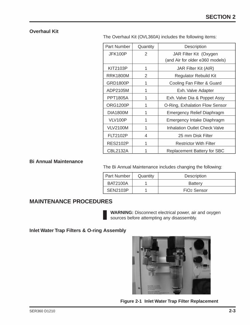
Inlet Water Trap Filters & O-ring Assembly
Figure 2-1 Inlet Water Trap Filter Replacement
Part Number Quantity Description
JFK100P 2 JAR Filter Kit (Oxygen(and Air for older e360 models)
KIT2103P 1 JAR Filter Kit (AIR)
RRK1800M 2 Regulator Rebuild Kit
GRD1800P 1 Cooling Fan Filter & Guard
ADP2105M 1 Exh. Valve Adapter
PPT1805A 1 Exh. Valve Dia & Poppet Assy
ORG1200P 1 O-Ring, Exhalation Flow Sensor
DIA1800M 1 Emergency Relief Diaphragm
VLV100P 1 Emergency Intake Diaphragm
VLV2100M 1 Inhalation Outlet Check Valve
FLT2102P 4 25 mm Disk Filter
RES2102P 1 Restrictor With Filter
CBL2132A 1 Replacement Battery for SBC
SECTION 2
SER360 D1210 2-3
Part Number Quantity Description
BAT2100A 1 Battery
SEN2103P 1 FiO2 Sensor

Oxygen Filter1 Unscrew the collection bowl from the inlet water trap.
2 Unscrew the filter holder.
3 Remove and replace the inlet filter and O-ring.
4 Reinstall the filter holder and reassemble the water trap assembly.
Note: If your air side filter is the same as the oxygen filter, thenperform the same procedure above to change the air filter.
Air Filter
1 Unscrew the retaining ring securing the water trap bowl to thefilter.
2 Unscrew the filter holder.
3 Remove and replace the inlet filter and O-ring.
4 Reinstall the filter holder and reassemble the water trap assembly.
Figure 2-2 Exhalation Valve Adapter Replacement
1 Access the Exhalation Valve Adapter by lifting the Retaining Latch and removing the Exhalation Valve and Exhalation Flow Sensor, see Figure 2-2 above.
2 To remove the silicon Exhalation Valve Adapter, use your fingerto grasp the Adapter and pull it straight out.
3 To replace the Exhalation Valve Adapter, orient the Adapter lip
MAINTENANCE, OVERHAUL & SOFTWARE UPGRADE
ValveAdapter
Adapter Lip
RetainingLatch
ADP2105MExhalation Valve Adapter
2-4 SER360 D1210
towards the inside of the exhalation valve housing and pressinto place.
4 Ensure that the Adapter is properly seated before re-installing the Exhalation Valve and Exhalation Flow Sensor.
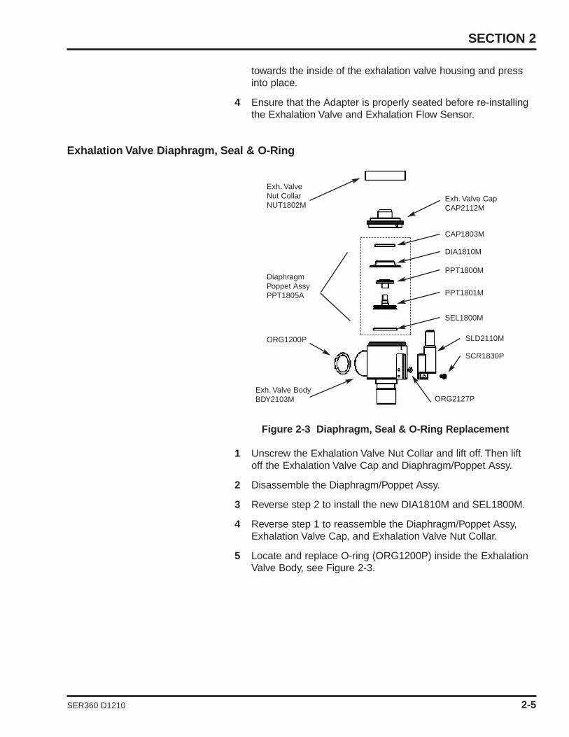
Exhalation Valve Diaphragm, Seal & O-Ring
Figure 2-3 Diaphragm, Seal & O-Ring Replacement
1 Unscrew the Exhalation Valve Nut Collar and lift off. Then lift off the Exhalation Valve Cap and Diaphragm/Poppet Assy.
2 Disassemble the Diaphragm/Poppet Assy.
3 Reverse step 2 to install the new DIA1810M and SEL1800M.
4 Reverse step 1 to reassemble the Diaphragm/Poppet Assy, Exhalation Valve Cap, and Exhalation Valve Nut Collar.
5 Locate and replace O-ring (ORG1200P) inside the Exhalation Valve Body, see Figure 2-3.
SECTION 2
Exh. Valve CapCAP2112M
CAP1803M
DIA1810M
PPT1800M
PPT1801M
SEL1800M
SLD2110M
SCR1830P
ORG2127P
Exh. ValveNut CollarNUT1802M
ORG1200P
Exh. Valve BodyBDY2103M
DiaphragmPoppet AssyPPT1805A
SER360 D1210 2-5

Emergency Relief Diaphragm
Figure 2-4 Inhalation Outlet Assembly
Figure 2-5 Emergency Relief Diaphragm Replacement
1 Access the Inhalation Outlet Assembly by removing the Lower Right Front Panel, see Figure 2-4 above.
2 Remove the Inhalation Outlet Assembly by removing the two retaining screws, see Figure 2-5 above.
3 Remove 4 screws from Emergency Valve Cap to expose the Emergency Relief Valve.
4 Insert finger and pull the Emergency Relief Diaphragm (DIA1800M) out of Inhalation Outlet Block.
5 Replace the Emergency Relief Diaphragm.
6 To reinstall components and assembly, reverse the above procedure.
In-Line Disk Filters and Restrictor with Filter
1 Remove Qty 6 screws securing e360 cover, remove the cover.
2 Using the System Pneumatic Diagram in Appendix C of this manual, locate and replace the Qty 4 disk filters P/N FLT2102P.
MAINTENANCE, OVERHAUL & SOFTWARE UPGRADE
EmergencyReliefDiaphragmDIA1800M Emergency
Valve Cap
InhalationOutlet BlockInhalation
Adapter
Outlet RetainingScrews
2-6 SER360 D1210
Inh. Outlet Assy

Note: The FLT2102P filters have Leur Lock connections and can bereplaced by twisting the adapters while holding the filter in your hand.
3 Using the Pneumatic Diagram in section 10 of this manual,locate and replace the RES2102P restrictor with filter. Whenreplacing the RES2102P, the arrow on the restrictor shouldface the direction of flow.
Note: If your e360 does not have the In-Line Disk Filters alreadyinstalled, Contact Newport Medical Instruments, Technical SupportDepartment to obtain needed filter adapters.
SBC Battery
1 Remove the cable clamp securing the SBC Battery P/N CBL2132A.
2 Remove the SBC Battery P/N CBL2132A from J1 on the SBC Board.
3 To reinstall, reverse steps 1 and 2.
Note: If your e360 does not already have the SBC Batteryinstalled, please contact Newport Medical Instruments, TechnicalSupport Department to obtain further instructions.
OVERHAUL PROCEDURES
WARNING: Disconnect electrical power, air and oxygensources before attempting any disassembly.
Inlet Water Trap Filter and O-ring Assembly
To replace the Inlet Filter and O-ring assemblies, follow theprocedures given in the Preventive Maintenance at the beginningof this section.
Air and Oxygen Inlet Regulator Rebuild
Figure 2-6 Inlet Regulator Rebuild
SECTION 2
Diaphragm
O-Ring
Cover
Spring
Slip Ring
SER360 D1210 2-7

To remove/install the Air and Oxygen Inlet Regulator, follow theprocedures in Section 4 of this manual, “Removal of ServoValves,Regulators, Inlet Block and Flow Sensor Block”.
NOTE: Inlet Regulators must be outside of the Ventilator for dis-assembly and re-assembly.
To install the Air and Oxygen Inlet Regulators Rebuild Kits, refer toFigure 2-6 and do the following:
1 Unscrew the brass cover from the regulator (no tool should be needed) and remove the spring, diaphragm, diaphragm washer, seat with O-ring, small spring, and ball (see Figure 2-6).
2 Replace the used parts, reversing the disassembly, with the parts from the Regulator Rebuild Kit P/N (RRK1800M).
NOTE: The Regulator must be in a vertical position in order toreassemble the Kit components.
3 Install the Regulator brass cover, hand tight and ensure all components are aligned.
NOTE: This procedure is the same for both the air and the oxygenregulators.
Exhalation Valve Adapter
To replace the Exhalation Valve Adapter, follow the proceduresgiven in the Preventive Maintenance at the beginning of thissection.
Exhalation Valve Diaphragm/Poppet Assembly
Refer to Drawing 2-3
1 Unscrew the Exhalation Valve Nut Collar and lift off. Then lift off the Exhalation Valve Cap and Diaphragm/Poppet Assembly.
2 Replace complete Diaphragm/Poppet Assembly (p/n PPT1805A).
3 Reverse step 1 to reassemble the Diaphragm/Poppet Assembly, Exhalation Valve Cap, and Exhalation Valve Nut Collar.
4 Locate and replace O-ring (ORG1200P) inside the Exhalation Valve Body, see Figure 2-3.
MAINTENANCE, OVERHAUL & SOFTWARE UPGRADE
2-8 SER360 D1210

Cooling Fan Filter & Guard
Figure 2- 7 Filter and Guard Assembly Replacement
Replace the Cooling Fan Filter and Guard Assembly (GRD1800P),see Figure 2-7.
Emergency Relief Diaphragm
To replace the Emergency Relief Diaphragm, follow theprocedures given in the Preventive Maintenance at the beginningof this section.
Emergency Intake Diaphragm
Figure 2-8 Emergency Intake Diaphragm Replacement
SECTION 2
Mixing BlockRetaining Screws (2)
Mixing Block
EmergencyIntake Valve
Emergency IntakeValve RetainingScrews (2)
SER360 D1210 2-9
Cooling FanFilter & Guard

1 Remove Top Cover following procedure in Section 4 of this manual, “Removal of Top cover”.
2 Remove Pneumatics Panel following procedure in Section 4 of this Manual, “Removal of Pneumatics Panel Assembly”.
3 Remove Inspiratory Flow Sensors following procedure in Section 4 of this manual, “Removal of Inspiratory Flow Sensors”.
4 Remove two Emergency Intake Valve retaining screws, see Figure 2-8 above.
5 Remove the Emergency Intake Valve using Needle Nose Pliers.
6 Replace the Emergency Intake Diaphragm (VLV100P) and reinstall assembly by reversing procedure above.
Inhalation Outlet Check Valve
Figure 2-9 Inhalation Outlet Check Valve
1 Remove the Mixing Block by removing the two retaining screws, see Figure 2-8.
2 Remove the Inhalation Adapter from the Inhalation Outlet Assembly, see Figure 2-5.
3 Insert finger and push out the Inhalation Outlet Check Valve, see Figure 2-9.
4 Replace the Inhalation Outlet Check Valve Diaphragm (VLV2100M).
5 To reinstall components and assembly, reverse above procedure.
MAINTENANCE, OVERHAUL & SOFTWARE UPGRADE
Inhalation OutletCheck Valve
2-10 SER360 D1210

In-Line Disk Filters and Restrictor with Filter
To replace the In-Line Disk Filters and Restrictor with Filter, followthe procedures given in the Preventive Maintenance at thebeginning of this section.
Note: If your e360 does not have the In-Line Disk Filters alreadyinstalled, Contact Newport Medical Instruments, Technical SupportDepartment to obtain needed filter adapters.
SBC Battery
To replace the SBC Battery P/N CBL2132A, follow the proceduresgiven in the Preventive Maintenance at the beginning of this section.
Note: If your e360 does not already have the SBC Batteryinstalled, please contact Newport Medical Instruments, TechnicalSupport Department to obtain further instructions.
BIANNUAL MAINTENANCE
Internal Battery
Replace the internal battery minimally every 2 years or as neededto meet operation requirements
To remove/install the Internal battery, follow the procedures inSection 4 of this manual, “Removal of Internal Battery”.
Caution: To avoid discharging battery voltage, do not allowany metal object (including tools) to touch battery connectors.
Warning: Observe correct polarity when reconnecting batteryconnectors.
Oxygen Sensor
Replace the oxygen sensor minimally every 2 years or as neededto meet operation requirements.
To remove/install the oxygen sensor, follow the procedure insection 4 of this manual (Removal and replacement of oxygensensor P/N SEN2103P).
Tubing
The tubing inside the e360 ventilator does not need to be replacedat any predetermined time interval; however, Newport is aware thattubing may occasionally need replacing. During the overhaulprocedure, carefully inspect all tubing for degradation, cracks, orbrittleness. If the tubing indicates any of those symptoms, replaceas necessary.
SECTION 2
SER360 D1210 2-11
MAINTENANCE, OVERHAUL & SOFTWARE UPGRADE
2-12 SER360 D1210
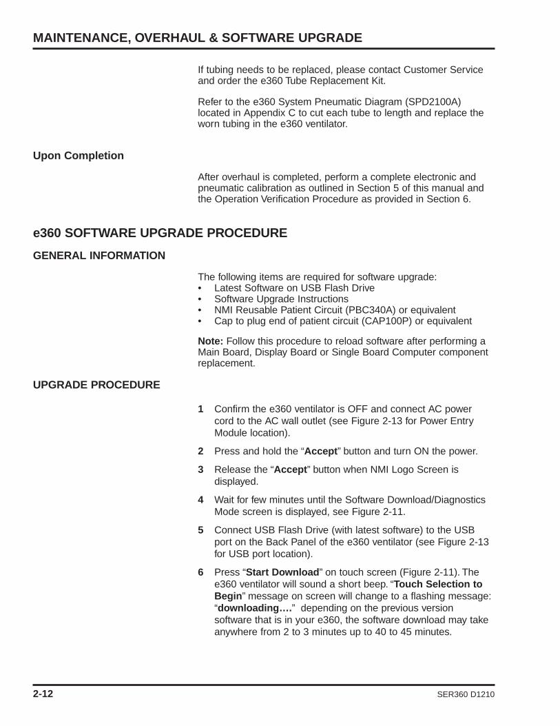
If tubing needs to be replaced, please contact Customer Serviceand order the e360 Tube Replacement Kit.
Refer to the e360 System Pneumatic Diagram (SPD2100A)located in Appendix C to cut each tube to length and replace theworn tubing in the e360 ventilator.
Upon Completion
After overhaul is completed, perform a complete electronic andpneumatic calibration as outlined in Section 5 of this manual andthe Operation Verification Procedure as provided in Section 6.
e360 SOFTWARE UPGRADE PROCEDURE
GENERAL INFORMATION
The following items are required for software upgrade:• Latest Software on USB Flash Drive • Software Upgrade Instructions • NMI Reusable Patient Circuit (PBC340A) or equivalent• Cap to plug end of patient circuit (CAP100P) or equivalent
Note: Follow this procedure to reload software after performing aMain Board, Display Board or Single Board Computer componentreplacement.
UPGRADE PROCEDURE
1 Confirm the e360 ventilator is OFF and connect AC power cord to the AC wall outlet (see Figure 2-13 for Power Entry Module location).
2 Press and hold the “Accept” button and turn ON the power.
3 Release the “Accept” button when NMI Logo Screen is displayed.
4 Wait for few minutes until the Software Download/Diagnostics Mode screen is displayed, see Figure 2-11.
5 Connect USB Flash Drive (with latest software) to the USB port on the Back Panel of the e360 ventilator (see Figure 2-13 for USB port location).
6 Press “Start Download” on touch screen (Figure 2-11). The e360 ventilator will sound a short beep. “Touch Selection to Begin” message on screen will change to a flashing message:“downloading….” depending on the previous version software that is in your e360, the software download may take anywhere from 2 to 3 minutes up to 40 to 45 minutes.

Figure 2-11 Software Download/Diagnostics Mode Screen
7 When software download is completed, ventilator will sound a short beep. “Download Complete” message will appear on the screen and flashing stops.
8 Turn OFF the power of the e360 ventilator.
9 Wait at least 10 seconds and turn the e360 ventilator power back ON.
10 Wait until “Ventilation Standby” screen appears.
11 Press “Start Ventilating” to begin ventilating.
12 NOTE: Because Air/O2 gas supplies are not connected you will get an “Air/O2 Loss” alarm. Disregard alarm while verifying software is installed correctly.
13 After “Start Ventilation” button is pressed, confirm that “Incompatible Software ….” Message does not show up on the screen. If this message appears on the LCD touch screen, then the software download was NOT completed successfully.Repeat 1 – 6 again. If the same problem still remains, then contact NMI representative for further assistance.
14 Press “Extended Functions” button on the Front control panel.
15 Press “Event History” button on LCD touch screen.
16 Confirm software is properly upgraded by checking software version number (see Figure 2-12, left upper corner).
SECTION 2
SER360 D1210 2-13

MAINTENANCE, OVERHAUL & SOFTWARE UPGRADE
2-14 SER360 D1210
Figure 2-12 Event History Log Screen
17 The new Software version is now downloaded successfully.
18 Remove USB Flash Drive from the USB Port on the back of the e360 ventilator.
Circuit Check Test and Diagnostic
WARNING: Before returning the e360 ventilator back for patientuse after the software upgrade, you must perform the following:
1 Turn OFF the power of the e360 ventilator.
2 Connect medical grade air source to Air Inlet on the Back Panel of the e360 ventilator and make sure that medical grade air source can provide at least 30 psi and does not exceed more than 90 psi. (see Figure 2-13 for Air Inlet).
3 Connect appropriate patient circuit to the e360 ventilator as shown in Figure 2-14. Occlude the patient circuit using a CAP.A filter and test lung are not required for this instruction.
4 Turn the power of the e360 ventilator back ON.
5 Wait until “Ventilation Standby” screen appears.
6 Follow the instructions that appear on LCD touch screen as shown in Figure 2-15.
7 Press “Circuit Check” button on LCD touch screen, and “Circuit Check Test in Progress” massage appears on LCD touch screen as shown in Figure 2-16.
8 When circuit test is completed successfully, “Circuit Check PASSED” message appears on LCD touch screen.
9 If circuit test failed, “Circuit Check FAILED” message appears on LCD touch screen. Please check the breathing circuit for leaks and press “Circuit Check” button on LCD touch screen and repeat Circuit Check. If circuit check does not pass, please contact NMI representative for further assistant.
10 Press “Setup & Calibration” button on the Control Panel.
11 Press “TECHNICAL” button on LCD touch screen, see Figure 2-17.
12 Press “Regional Settings” button on LCD touch screen, see Figure 2-17.
13 Press “Altitude” button on LCD touch screen and “_ ft/_ m”setting will start flashing.
14 While the numbers are flashing, rotate the Encoder Adjustment Knob to change the Altitude level to where this instruction is going to be performed. (For example if the location is at the sea level, then set Altitude setting to “0 m / 0 ft”).
15 Press “Accept” button to set the new Altitude setting and flashing will stop.
16 Wait for 15 ~ 20 seconds.
17 Turn “OFF” the power of the e360 ventilator.
18 Press and hold “Accept” button and then turn “ON” the power of the e360 ventilator to enter into Software Download screen on the e360 ventilator shown in Figure 2-11. “Accept”button can be released once the ventilator sounds a short beep.
19 Press “Start Diagnostics” button on LCD touch screen and the Diagnostic Data screen will appear as shown in Figure 2-18.
20 Press “Trig Button” on the Control Panel. Rotate the Encoder Adjustment Knob to change value in display window to “d9”and press “Accept” button.
21 Occlude the breathing circuit from the y-piece using a CAP.(Do not use test lung).
22 Press “Manual Inflation” button to start Exhalation Flow Sensor calibration, d9. Wait for 30 sec ~ 1 minute until “TSI Air flow:“ and “Exhale Flow:“ numbers start to increase gradually and the air flow is delivered from the e360 ventilator.It requires 6 ~ 10 minutes to complete Exhalation Flow Sensor calibration, see Figure 2-18).
SECTION 2
SER360 D1210 2-15

MAINTENANCE, OVERHAUL & SOFTWARE UPGRADE
2-16 SER360 D1210
23 When flow delivered from the e360 ventilator stops and “Message” changes to “Test Completed”, then the Exhalation Flow Sensor calibration is successfully completed, see Figure 2-18.
24 Turn OFF the power of the e360 ventilator.
25 Disconnect medical grade air source from Air Inlet on the Back Panel of the e360 ventilator.
26 Disconnect AC power cord from AC wall outlet.
27 Upon completion of the installation of software upgrade, you must complete the attached “Newport e360 Ventilator Software Update Form” with serial numbers, part numbers and signatures and return it to Newport Regulatory Department via Fax at +1.714.427. 0839.
If you have any questions please contact Newport TechnicalService Department:
Tel: +1.714.427.5811 ext. 500, Fax: +1.714.427-0572
Email: [email protected]
Figure 2-13 Back Panel of e360 Ventilator
Ne
wp
ort
Mo
de
l e
36
0
Se
ria
l #
XX
XX
XX
USBConnection
Cooling FanFilter
Power EntryModule
O2 Inlet Air Inlet

SECTION 2
SER360 D1210 2-17
Figure 2-14 Patient Circuit Setup
Figure 2-15 Ventilation Standby Screen
Y-Piece
Breathing Circuit
Option 1
WeaningMechanic
Advanced
Basic
Option 1CircuitCheck
Sensors
TechnicalSetup
PatientSetup
MODE: VC/ACMVVentilation Standby
10-03-06 14:25
Circuit Check
2. Occlude circuit Y-piece
3. Presss Circuit Check button to begin
1. Attach complete breathing circuit
ADULT
START VENTILATING
MVEPEEPPpeak VTE RR tot--------------- ---
FIO2mL/kg

Figure 2-16 Circuit Check Screen
Figure 2-17 Technical Screen
2-18 SER360 D1210
MAINTENANCE, OVERHAUL & SOFTWARE UPGRADE

Figure 2-18 Diagnostic Data Screen
SER360 D1210 2-19
SECTION 2


SER360 D1210 2-21
SECTION 2
NEWPORT e360 VENTILATOR SOFTWARE UPGRADE FORM
COMPLETE FORM MUST BE FAXED TO NEWPORT REGULATORY AFFAIRS UPONCOMPLETION OF UPGRADE.
Fax completed form to: 1.714.427.0839 attention RA/QA Or email requested information to: [email protected]
Facility Name: __________________________________________________________________
Facility Address: ________________________________________________________________
______________________________________________________________________________
e360 Model: WWE WWP WWS USS Other ____________
Language: ____________________________________________________
Current Hours: __________________________________________________
e360 Model Serial Number: ________________________________________
Old software version: ____________________________________________
Updated software version: ________________________________________
Company performing service: ______________________________________
Address of company performing service:______________________________
Software Updated
by: ____________________________________ Date: ______________
Exhalation Flow Sensor Calibration, d9 performed
by: ____________________________________ Date: ______________


SER360 D1210
3. TROUBLESHOOTING GUIDE
Troubleshooting Guide .......................................... 3-1Device Alert Messages ........................................ 3-3


TROUBLESHOOTING GUIDE
Table 3-1 may provide guidance in determining the cause andpossible corrective action for ventilator problems. Newport doesnot guarantee that the suggested corrective action will solve theproblem.
Contact Newport Technical Service Department for additionalassistance.
Table 3-1 Troubleshooting Guide
SECTION 3
Problem Potential Cause Suggested Action
Fail Circuit Check Leak from patient circuit.Leak from exhalation section.Leak from inhalation section.Leak from tubing connection insidethe ventilator.
Inspect patient circuit.Disassemble exhalation valve to inspectexhalation valve diaphragm and seal.Inspect exhalation valve adapter.Tighten inhalation flow outlet.Tighten oxygen sensor.Inspect emergency relief diaphragm.Inspect pneumatic tubing inside the ventilator.Inspect TSI air/oxygen flow sensorsassembly.Clean or replace emergency intakediaphragm.Inspect rubber seal between inhalationoutlet block and mixer block.
Flow Sensor Error/Bad Defective exhalation flow sensor.Defective exhalation flow sensorcables, outside and inside.Defective cable from exhalationsensor board to main board.Defective exhalation sensor board.
Replace exhalation flow sensor.Replace exhalation flow sensor cables,outside and inside.Replace cable from exhalation sensorboard to main board.Replace the exhalation sensor board.
Ventilator cannot achieveor maintain correct tidalvolume, plateau pressure,or baseline pressure.
Pressure relief valve regulatorfailure.Crossover solenoid valve failure.Machine zero solenoid valvefailure.
Perform the Operational VerificationProcedure to diagnose the problem.
Replace any parts that may be defective.
Pressure Bar graph doesnot show pressure rise.
Machine zero solenoid valvefailure.
Analog board malfunction.
Replace solenoid and / or Analog PCB.
SER360 D1210 3-1

TROUBLESHOOTING GUIDE
Problem Potential Cause Suggested Action
Internal battery does notcharge.
Defective battery or batterycharging hardware.
Replace internal battery or replace theDC-DC power supply PCB.
Loss of battery power. Battery missing, discharged ordefective. Defective battery hardware.
Recharge or replace battery.Replace DC-DC power supply PCB.
Low supply gas alarm Supply pressure is not withinspecified range (30 – 90 psig).Faulty gas supplyFaulty transducer on Analog boardPressure regulator not setcorrectly or faultyTube on transducer has becomedisconnected
Ensure that both gas supplies have apressure of at least 30 psig.Verify gas sources are at correctpressuresReplace Analog boardCalibrate or replace regulatorVerify all tubes are connected properly
No flow or low flow frominspiratory port duringinspiratory phase of amandatory breath.
Inlet regulator failure or servovalve failure.
Calibrate air and oxygen regulators;replace if calibration is not successful.
Ventilator cannot cycle,audible alarm on, anderror message displayed inmessage window.
Based on error message. Calibrate servo valves; replace ifcalibration is not successful.Refer to Table 3-2, Device AlertMessages.
Zero monitored exhaledflow.
Flow Sensor Cable disconnected.Flow sensor defective.Defective Exhalation Flow SensorPCB.
Reconnect cable to exhalation flowsensor. Verify that pins in cableconnector are not damaged.Replace flow sensor.Replace Exhalation Flow Sensor PCB.
Monitored values forexhaled flows or volumesdiffer from settings.
Occluded or missing bacteria filter.Dirty Exhalation flow sensor.Exhalation heater failure.Vent settings for “Circuit Type”humidity setup are incorrect forhumidifier system in use.Replace the bacteria filter.
Disassemble and clean the ExhalationModule, replace the exhalation flowsensor.Feel the bacteria filter. If it is not warm tothe touch, replace the exhalation heater.Correct “Circuit Type” selection in PatientSet-up.
Monitored FIO2 valuesdiffer from setting.
Defective oxygen sensor.Defective Analog Board
Replace the oxygen sensor.Replace Analog Board.
No audible alarm. Defective alarm speaker, Soundprocessor board or SBC.
Replace alarm speaker or soundprocessor board or SBC.
Press F1 to continue isdisplayed on LCD duringpower on.
Depleted battery on SBC board.Defective SBC.
Replace battery on SBC board.Replace SBC Board.
LCD shows white screenonly.
Corrupted files on CF card.Defective SBC Board.
Replace CF card.Replace SBC Board.
3-2 SER360 D1210

SER360 D1210 3-3
SECTION 3
Device Alert Violation Priority DefinitionsViolation Messages Level
Control communicationsfailure
Monitor µP Failed High The monitor processor does not respond to arequest from the control processor. The monitorprocessor is not running.
Control CPU failure Control CPU Failed High The control processor on the main PCB is bad.
Control exception failure M Internal System High The control processor has detected anabnormal operation such as illegal instructionor division by zero that was generated by thecontrol software.
Control RAM Failure Control RAM Failed High Random access memory that is used by thecontrol processor on the main PCB isdamaged.
Control ROM failure Control ROM FailedHigh Read only
memory that stores the code of the control processorhas an incorrect check sum.
DEVICE ALERT MESSAGES
Table 3-2 defines the Device Alert violations and messages thatmay be displayed in the message window. The first line in themessage window displays the date and time of the error; thesecond line displays the error message.
Table 3-2 Device Alert Messages
Control task continuityfailure
Control TasksFailed
High Software tasks of the control processor haveoperated out of sequence.
Dual RAM failure Dual RAM Failed High Random access memory that is sharedbetween the control and monitor processors isdamaged.
Problem Potential Cause Suggested Action
LCD shows black screenonly
Corrupted files on CF cardDefective SBC BoardDefective Display BoardDefective LCD display
Replace CF cardVerify voltage on the 5th solder pad fromthe top, left side of connector LCD 1 isat least 2.5 volts. If not Replace SBCboardReplace Display BoardReplace LCD Display
E360 power resets Defective SBC boardDefective Power Sequence Board
Replace SBC boardReplace Power Sequence Board
Software fails to Download Faulty USB Download sticks Replace USB Software sticks
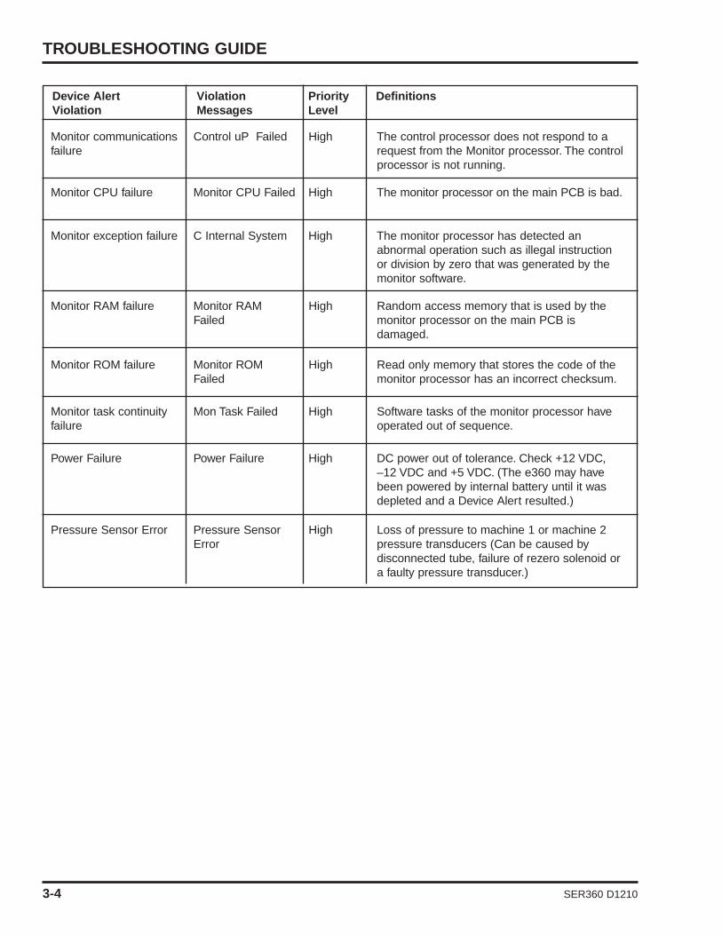
Device Alert Violation Priority DefinitionsViolation Messages Level
Monitor ROM failure Monitor ROMFailed
High Read only memory that stores the code of themonitor processor has an incorrect checksum.
Monitor task continuityfailure
Mon Task Failed High Software tasks of the monitor processor haveoperated out of sequence.
Power Failure Power Failure High DC power out of tolerance. Check +12 VDC,–12 VDC and +5 VDC. (The e360 may havebeen powered by internal battery until it wasdepleted and a Device Alert resulted.)
Pressure Sensor Error Pressure SensorError
High Loss of pressure to machine 1 or machine 2pressure transducers (Can be caused bydisconnected tube, failure of rezero solenoid ora faulty pressure transducer.)
TROUBLESHOOTING GUIDE
3-4 SER360 D1210
Monitor communicationsfailure
Control uP Failed High The control processor does not respond to arequest from the Monitor processor. The controlprocessor is not running.
Monitor CPU failure Monitor CPU Failed High The monitor processor on the main PCB is bad.
Monitor exception failure C Internal System High The monitor processor has detected anabnormal operation such as illegal instructionor division by zero that was generated by themonitor software.
Monitor RAM failure Monitor RAMFailed
High Random access memory that is used by themonitor processor on the main PCB isdamaged.

SER360 D1210
4. COMPONENT REMOVAL& REPLACEMENT
Removal of Key Components– Preparation .................................................... 4-1– Tools Required .............................................. 4-1
Exhalation Valve and Exhalation FlowSensor ............................................................ 4-2
Exhalation Flow Sensor Cable (outside) (CBL2123P) ...................................................... 4-3
Top Cover (CVR2101M)........................................ 4-3Front Panel Assembly (DSP2102A)...................... 4-4Main Board (PCB2100A) ...................................... 4-5Main Board Support (CVR2103M)........................ 4-6Display Board (PCB2102A) .................................. 4-7Touch Screen Interface Board (PCB2105P) ........ 4-8Large LCD Cable (CBL2105A) ............................ 4-9Front Panel Cover (CVR2104M).......................... 4-10Optical Encoder (ENC1800P).............................. 4-11Alarm LEDs .......................................................... 4-11LCD Display (DSP2105P).................................... 4-11Touch Screen (PNL2105P) .................................. 4-12Pneumatics Panel Assembly (SVO2101A).......... 4-13Servo Valves, Regulators, Inlet Block and Flow
Sensor Block .................................................. 4-15Regulator and Solenoid Assembly
(BKT2105A) .................................................... 4-16Inspiratory Flow Sensors .................................... 4-17Main Flow Outlet Block Assembly
(BLK2108M) .................................................... 4-18Oxygen Sensor (SEN2103P) .............................. 4-19Inhalation Outlet Block and Mixing Bloc
Assembly ........................................................ 4-20Analog Board (PCB2104A).................................. 4-21

Heater Assembly (HTR1200A) ............................ 4-22Exhalation Manifold (MNF2110A)........................ 4-23Exhalation Flow Sensor Board (PCB2103P) ...... 4-24Battery (BAT2100A) ............................................ 4-25AC to DC Power Supply (PWR2100P)................ 4-26DC to DC Power Supply Board
(PCB2101A) .................................................... 4-27Sound Processor Board (PCB2106P) ................ 4-28Single Board Computer (SBC2100P).................. 4-28Power Sequence Board (PCB2107A) ................ 4-30

SECTION 4
SER360 D1210 4-1
Removal of Key Components
Unless instructed otherwise, reinstall parts by reversing thedisassembly procedure.
PreparationBefore performing any repair or service on the e360 ventilator dothe following:
1 Disconnect the power.
2 Shut off or disconnect the air and oxygen gas supplies.
3 Put on an ESD wrist strap and perform procedures in an ESD safe environment.
Tools Required• #0 Philips Screw Driver• #1 Philips Screw Driver• #2 Philips Screw Driver• #1 Flat Screw Driver• 5/64” Hex Key• 7/32” Nut Driver or Wrench• 11 mm Nut Driver or Wrench• Torque Wrench set for 8 inch/pounds• Anti Static Wrist Strap • Anti Static Parts Bin
WARNING To avoid possibility of electric shock, do not touch thepower supply transformer when servicing the ventilator.
These instructions are intended for use only by a Newport MedicalInstruments factory-trained technician. Do not perform anyunauthorized modifications or repairs to the ventilator or itscomponents.
Caution To avoid damaging equipment, always use standardelectrostatic discharge (ESD) precautions, including an ESD wriststrap, when servicing the ventilator.
Note: If the Main Board, Display Board or Single Board computercomponents are replaced the e360 software must be reloaded.Follow the Software Upgrade Procedure in Section 2 to loadsoftware. Contact Newport Technical Service if you need asoftware kit.

COMPONENT REMOVAL & REPLACEMENT
4-2 SER360 D1210
Removal of Exhalation Valve and Exhalation Flow Sensor
Caution: The Exhalation Flow Sensor is a precise yet delicateinstrument. Take care when handling not to disturb themeasuring wires. The life cycle of the sensor is limited and willdepend on observance of safe handling precautions and theability to calibrate the sensor. Always make sure that the flowsensor is completely dry before installation.
Figure 4-1 Exhalation Valve and Exhalation Flow Sensor
Refer to figure 4-1 and follow these steps:
1 Open the Front Panel Door on the lower left front of the ventilator to expose Exhalation Valve EXH2105A and Flow Sensor FLS2101P.
2 Remove the Exhalation Valve EXH2105A by releasing the retaining latch.
3 Disconnect the Flow Sensor Cable CBL2123P from the plastic body of the Flow Sensor FLS2101P by pulling cable straight up. Do not twist.
4 With a twisting motion, pull the plastic Flow Sensor FLS2101P away from the outlet of the Exhalation Valve EXH2105A.
5 To reinstall the Flow Sensor and Exhalation Valve EXH2105A, reverse the above steps.
NOTE: To reconnect the cable to the sensor body, take care to lineup the sensor port to the notch in the cable connector. Presstogether, do not twist.
To disconnectcable CBL2123Pfrom Exh. ManifoldMNF2110A, pullthe collet of thecable straight out.
To disconnectcable CBL2123Pfrom Exh. FlowSensor FLS2101P,pull the connectorstraight up.
Removal and Replacement of Exhalation Flow Sensor Cable(outside) CBL2123P
1 Perform above steps for removal of Exhalation Valve and Exhalation Flow Sensor.
2 Remove the Exhalation Flow Sensor Cable (outside) CBL2123P fromthe Exhalation Manifold MNF2110A by pulling the collet of the cable connector.
3 To reinstall the cable to the Exhalation Manifold MNF2110A, align the key on the connector with the notch of the female connector on the Exhalation Manifold MNF2110A.
Note: The lock mechanism of the connector can be easily released bypulling the collet of the connector. Do NOT disconnect the connector bypulling the wire.
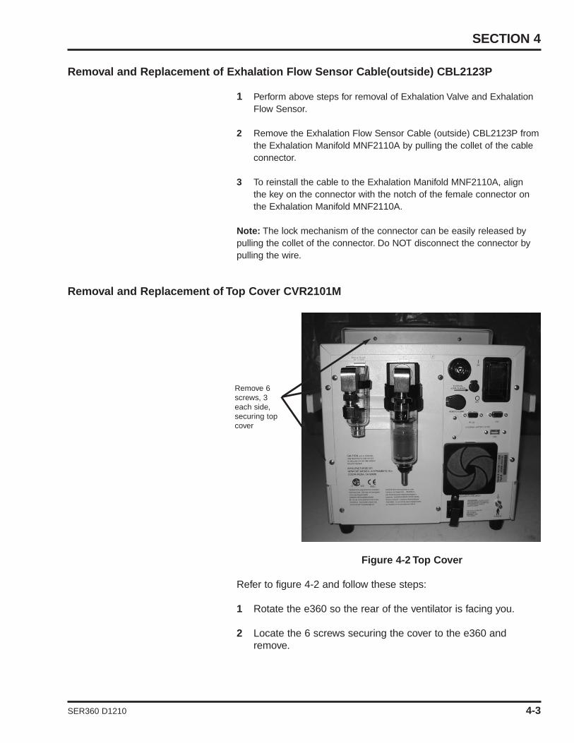
Removal and Replacement of Top Cover CVR2101M
Figure 4-2 Top Cover
Refer to figure 4-2 and follow these steps:
1 Rotate the e360 so the rear of the ventilator is facing you.
2 Locate the 6 screws securing the cover to the e360 and remove.
SECTION 4
Remove 6screws, 3each side,securing topcover
SER360 D1210 4-3

COMPONENT REMOVAL & REPLACEMENT
4-4 SER360 D1210
3 Grab the handles on the sides of the e360 ventilator, pull the sides away from the chassis and slide the cover off of the e360 ventilator.
4 To reinstall, reverse above steps 2 and 3.
Removal and Replacement of Front Panel Assembly DSP2102A
Figure 4-3 Front Panel Assembly DSP2102A
Refer to 4-3 and follow these steps:
1 Perform steps 1 and 2 for removal of top cover.
2 Locate the four screws securing the front panel assembly to the chassis of the e360 ventilator and remove.
3 Carefully pull forward and away the front panel assembly from the e360 ventilator chassis. Locate and remove the following cables.• CBL2101A from J2 on PCB2100A• CBL2118A from J13 on PCB2100A• CBL2110A from J8 on PCB2100A• CBL2113A from J10 on PCB2100A• Air and oxygen servo valve cables from J705 (Air) and
J706 (Oxygen) on PCB2100A• CBL2107A from J708 on PCB2100A• CBL2127A from J9 on PCB2100A• CBL2105A from connection LCD1 on SBC2100P• 3 wire cable of CBL2112A from connection TS1 of
SBC2100P. TS1 is a 6 pin connector located adjacent to the speaker SPK1.
Remove 4screws, 2each side

SECTION 4
Remove 4screws and
washers
CBL2106connected To
J4 onPCB2100A
LCD cableCBL2105A
CablesCBL2112A to
SBC2100P
CBL2102A &CBL2125Aconnected toP308 & P309on PCB2100A
SER360 D1210 4-5
• 2 wire cable of CBL2112A from connection IR of SBC2100P. IR is a 5 pin connector located on the bottom of SBC2100P.
4 After all above cables are removed, fully remove the front panel assembly and set on a stable surface.
5 To reinstall, reverse above steps 2 and 3.
Note: Cable CBL2112A splits to two connectors: 5-pin connectorwith 2 wires and 6-pin connector with 3 wires. Ensure the 3 wiresface outside when connecting the 6-pin connector on SBC2100P.
Note: There is a small hole adjacent to J9 on PCB2100A, which isto polarize the connector.
Removal and Replacement of Main Board PCB2100A
Figure 4-4 Main Board PCB2100A
Refer to figure 4-4 and follow these steps:
1 Perform steps above for removal of Front Panel Assembly DSP2102A.
2 Remove cable CBL2106A from J4 on PCB2100A.
3 Remove cable CBL2102A from P308 and CBL2125A from P309 on PCB2100A.
4 Remove 4 screws and washers securing main board to the main board support.

COMPONENT REMOVAL & REPLACEMENT
4-6 SER360 D1210
5 For ESD protection, place the main board in an ESD safe container.
6 To reinstall, reverse above steps 2 and 3. Reference thesystems wiring diagram in Appendix C of this manual.
Note: If the main board PCB2100A is replaced, the e360 ventilatorwill need sofware reloaded and D1, D2, D4 and D9 calibrationsperformed.
Note: Refer to Section 2 for Software Upgrade Procedure. Refer toSection 5 for all the other calibrations.
Removal and Replacement of Main Board Support CVR2103M
Figure 4-5 Main Board Support CVR2103M
Refer to figure 4-5 and follow these steps:
1 Perform steps above for removal of Front Panel Assembly DSP2102A.
2 Remove cable CBL2106A from J4 on PCB2100A.
3 Remove the cables CBL2125A and CBL2102A from the top LEDs.
4 Remove Qty 4 screws and washers securing the main board support to the front panel assembly.
5 Carefully lift up on the main board support and feed the cables CBL2105A, CBL2106A and CBL2112A through the cut out on the main board support.
Main board,PCB2100A
CBL2106 connectedto J4 on PCB2100A
CBL2102A andCLB2125A
CVR2103M
Remove 4screws, 2 eachside

SECTION 4
Encodercable andJ209
Remove9 screws
PCB2102A
CBL2112A PCB2105P 2 screws securePCB2105P
4 pin ribbon cable
SER360 D1210 4-7
6 Place the main board support with main board in an ESD safe container.
7 To reinstall, reverse above steps 2 through 5.
Note: Cable CBL2102A connects from P308 on PCB2100A to thetop Red LED. Cable CBL2125A connects from P309 onPCB2100A to the top Amber LED.
Removal and Replacement of Display Board PCB2102A
Figure 4-6 Display Board PCB2102A
Figure 4-7 Touch Screen Board PCB2105P
Refer to figures 4-6 and 4-7 and follow these steps:

COMPONENT REMOVAL & REPLACEMENT
4-8 SER360 D1210
1 Perform steps above for removal of Main Board Support.
2 Remove the 4 pin ribbon cable from header H2 on the touch screen interface board PCB2105P.
3 Remove cable CBL2112A from header H1 on the touch screen interface board PCB2105P.
4 Remove Qty 9 screws and washers securing the PCB2102A to the chassis of the DSP2102A.
5 Carefully lifting up on the display board from the lower left corner near the encoder, locate and remove the cable of the encoder from J209 on the PCB2102A.
6 Remove the lamp cable of LCD DSP2105P from JP204 on PCB2102A.
7 Push on the tab and remove front panel membrane cable from JP202 on PCB2102A.
8 Place the display board in an ESD safe container.
9 To reinstall, reverse above steps 2 through 7.
Note: If the Display Board PCB2102A is replaced, the e360ventilator will need the software reloaded. Refer to Section 2 forSoftware Upgrade Procedure.
Removal and Replacement of Touch Screen Interface Board PCB2105P
Refer to figure 4-7 above and follow these steps:
1 Perform steps above for removal of Display Board PCB2102A
2 Locate and remove 2 screws, washers and nuts securing the PCB2105P to the display board.
3 To reinstall, reverse step 2.
SECTION 4
LCD housingBKT2104M
CBL2105A
4 nuts, 2 each sidesecuring LCD hous-
ing BKT2104M tofront panel cover
Double sidedtape locatedunder cable
Ground wireand nut
Cable restraintand nut
SER360 D1210 4-9
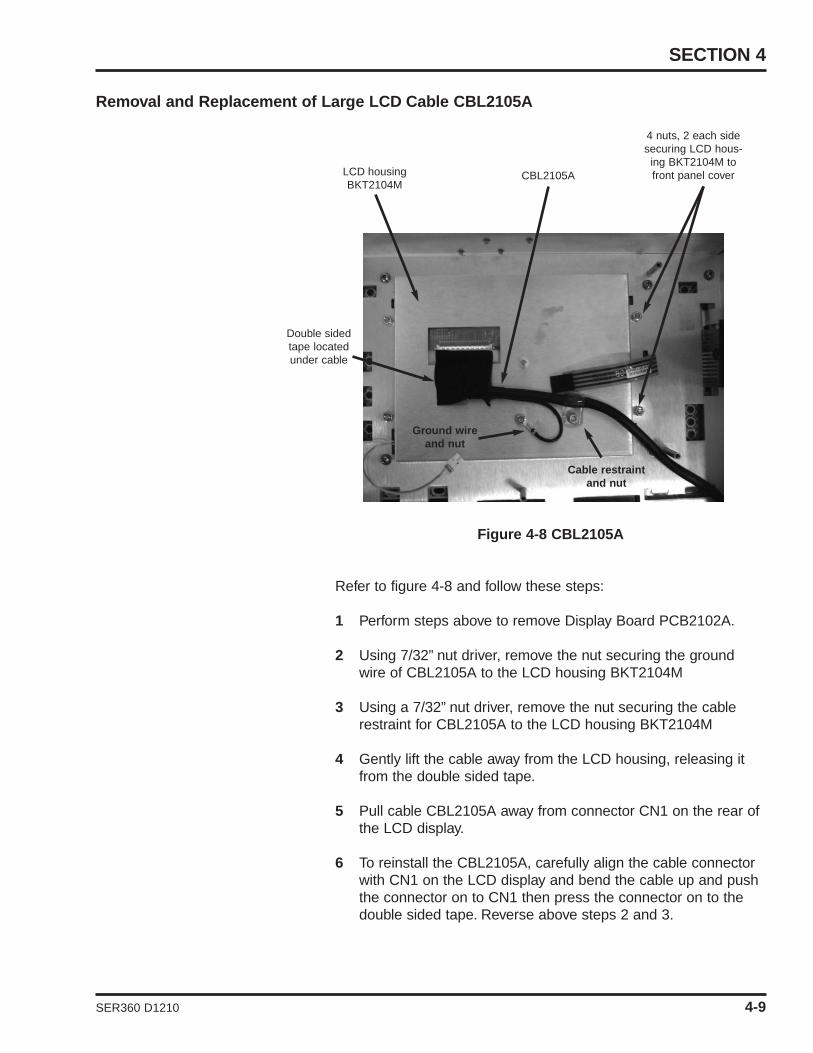
Removal and Replacement of Large LCD Cable CBL2105A
Figure 4-8 CBL2105A
Refer to figure 4-8 and follow these steps:
1 Perform steps above to remove Display Board PCB2102A.
2 Using 7/32” nut driver, remove the nut securing the ground wire of CBL2105A to the LCD housing BKT2104M
3 Using a 7/32” nut driver, remove the nut securing the cable restraint for CBL2105A to the LCD housing BKT2104M
4 Gently lift the cable away from the LCD housing, releasing it from the double sided tape.
5 Pull cable CBL2105A away from connector CN1 on the rear of the LCD display.
6 To reinstall the CBL2105A, carefully align the cable connector with CN1 on the LCD display and bend the cable up and push the connector on to CN1 then press the connector on to the double sided tape. Reverse above steps 2 and 3.
COMPONENT REMOVAL & REPLACEMENT
Remove8 screws
CVR2104MBZL2105M Nut securing flat ribbonground cable
Encoder knobis located onfront of panel
4-10 SER360 D1210
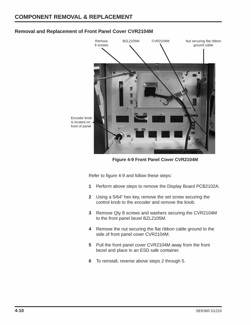
Removal and Replacement of Front Panel Cover CVR2104M
Figure 4-9 Front Panel Cover CVR2104M
Refer to figure 4-9 and follow these steps:
1 Perform above steps to remove the Display Board PCB2102A.
2 Using a 5/64” hex key, remove the set screw securing the control knob to the encoder and remove the knob.
3 Remove Qty 8 screws and washers securing the CVR2104M to the front panel bezel BZL2105M.
4 Remove the nut securing the flat ribbon cable ground to the side of front panel cover CVR2104M.
5 Pull the front panel cover CVR2104M away from the front bezel and place in an ESD safe container.
6 To reinstall, reverse above steps 2 through 5.

SECTION 4
SER360 D1210 4-11
Removal and Replacement of Optical Encoder ENC1800P
1 Perform above steps for removal of the front panel cover CVR2104M.
2 Using an 11mm wrench, remove the nut and washer securing the encoder to the front panel cover CVR2104M.
3 To reinstall, reverse the above step 2.
Note: When securing the encoder with the nut and washer, tightenthe nut to 8 in/lbs of torque.
Removal and Replacement of Alarm LEDS
1 Perform above steps for removal the front panel cover CVR2104M.
2 For each of the alarm LEDS, remove Qty 2 screws securing the boards to the CVR2104M.
3 To reinstall, reverse above step 2.
Note: The red LED is p/n LED2101P and amber LED is p/nLED2102P.
Removal and Replacement of LCD Display DSP2105P
Refer to figure 4-8 and 4-9 and follow these steps:
1 Perform above steps for removal of CBL2105A.
2 Remove the 4 nuts and washers securing the LCD housing BKT2104M to the CVR2104M.
3 Remove the 4 screws securing the BKT2104M to the LCD display DSP2105P.
4 To reinstall, reverse above steps 2 and 3.
COMPONENT REMOVAL & REPLACEMENT
TAP1200P
BZL2105M
Affix tape 0.10” from the inside edge
4-12 SER360 D1210
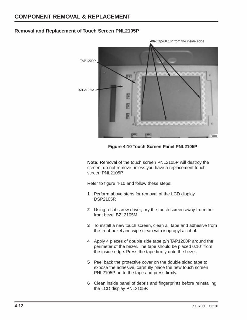
Removal and Replacement of Touch Screen PNL2105P
Figure 4-10 Touch Screen Panel PNL2105P
Note: Removal of the touch screen PNL2105P will destroy thescreen, do not remove unless you have a replacement touchscreen PNL2105P.
Refer to figure 4-10 and follow these steps:
1 Perform above steps for removal of the LCD display DSP2105P.
2 Using a flat screw driver, pry the touch screen away from the front bezel BZL2105M.
3 To install a new touch screen, clean all tape and adhesive fromthe front bezel and wipe clean with isopropyl alcohol.
4 Apply 4 pieces of double side tape p/n TAP1200P around the perimeter of the bezel. The tape should be placed 0.10” from the inside edge. Press the tape firmly onto the bezel.
5 Peel back the protective cover on the double sided tape to expose the adhesive, carefully place the new touch screen PNL2105P on to the tape and press firmly.
6 Clean inside panel of debris and fingerprints before reinstalling the LCD display PNL2105P.
SECTION 4
4 screws, 2 each side secures PNL2102M
6 screws, 3 on each side secures CVR2106M
SER360 D1210 4-13
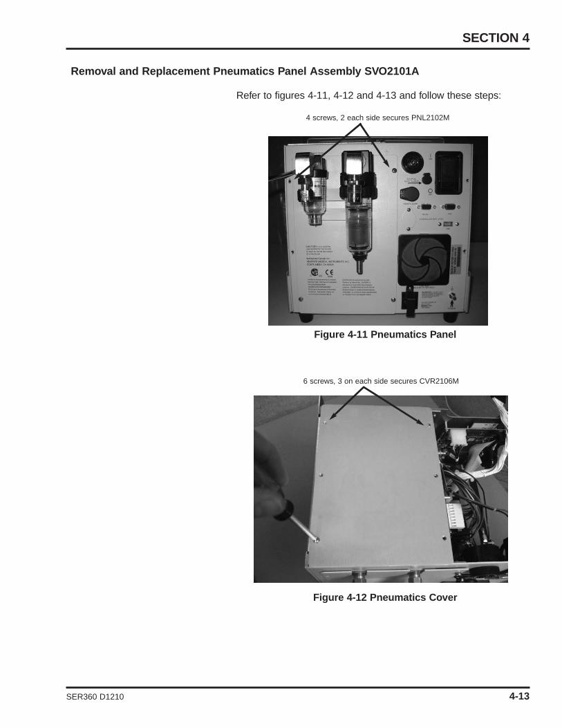
Removal and Replacement Pneumatics Panel Assembly SVO2101A
Refer to figures 4-11, 4-12 and 4-13 and follow these steps:
Figure 4-11 Pneumatics Panel
Figure 4-12 Pneumatics Cover
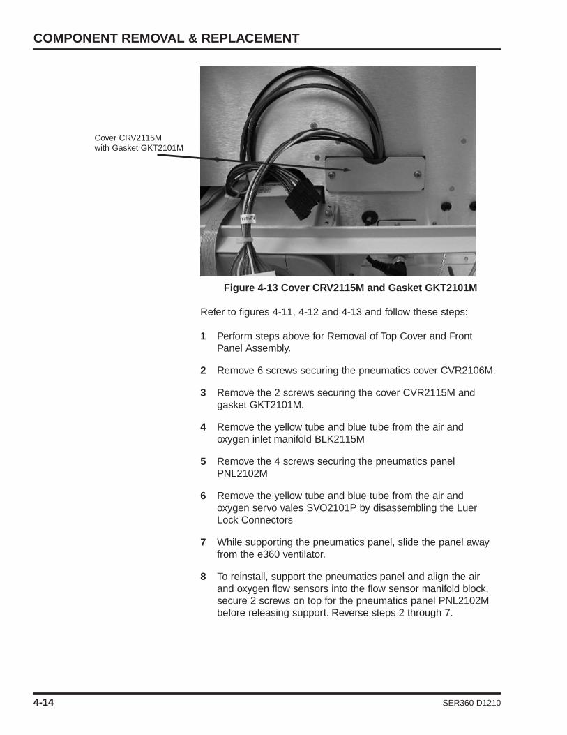
Figure 4-13 Cover CRV2115M and Gasket GKT2101M
Refer to figures 4-11, 4-12 and 4-13 and follow these steps:
1 Perform steps above for Removal of Top Cover and Front Panel Assembly.
2 Remove 6 screws securing the pneumatics cover CVR2106M.
3 Remove the 2 screws securing the cover CVR2115M and gasket GKT2101M.
4 Remove the yellow tube and blue tube from the air and oxygen inlet manifold BLK2115M
5 Remove the 4 screws securing the pneumatics panel PNL2102M
6 Remove the yellow tube and blue tube from the air and oxygen servo vales SVO2101P by disassembling the Luer Lock Connectors
7 While supporting the pneumatics panel, slide the panel away from the e360 ventilator.
8 To reinstall, support the pneumatics panel and align the air and oxygen flow sensors into the flow sensor manifold block, secure 2 screws on top for the pneumatics panel PNL2102M before releasing support. Reverse steps 2 through 7.
COMPONENT REMOVAL & REPLACEMENT
Cover CRV2115Mwith Gasket GKT2101M
4-14 SER360 D1210

SECTION 4
Inlet block BLK2115M
PNL2102M
Servo ValveSVO2101P
Flow sensorblock
BLK2101M
RegulatorREG1800P
SER360 D1210 4-15
Removal and Replacement of Servo Valves, Regulators, Inlet Blocksand Flow Sensor Block
Figure 4-14 Pneumatics Panel Assembly SVO2101A
Refer to figure 4-14 and follow these steps:
1 Perform above steps for removal of pneumatic panel assembly SVO2101A.
Note: To replace servo valves, regulators, inlet blocks or the flowsensor block, all screws securing listed components need to beremoved.
2 Remove 4 screws, 2 each securing the air and oxygen inlet blocks to PNL2102M.
3 Remove 8 screws, 4 each securing the air and oxygen servo valves to PNL2102M
4 Remove 2 screws securing the flow sensor block to PNL2102M.
5 Lift all parts away from the panel PNL2102M at the same time,then disassemble each component as needed.
6 To reassemble, reverse steps 2 through 5. Ensure the servo vales and regulators are aligned during reassembly.
Note: If replacing either of the servo valves or regulators,calibrations D1 and / or D2 and calibration of the regulators willneed to be performed. Refer to Section 5 for D1, D2, and regulatorcalibration.
COMPONENT REMOVAL & REPLACEMENT
2 screws, 1 each side securingBKT2105A to e360
Regulator and solenoidassembly BKT2105A
Crossover solenoidSOL1501P
Exhalation ServoVavle VLV1806P
Emergency ReliefSolenoid SOL1501P
Machine 1 PressureRezero SolenoidSOL1501P
Machine 2 PressureRezero SolenoidSOL1501P
Safety RegulatorREG1802P
Exhalation ServoRegulator REG1701P
4-16 SER360 D1210
Removal and Replacement of Regulator and Solenoid Assembly BKT2105A
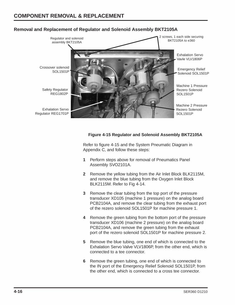
Figure 4-15 Regulator and Solenoid Assembly BKT2105A
Refer to figure 4-15 and the System Pneumatic Diagram inAppendix C, and follow these steps:
1 Perform steps above for removal of Pneumatics Panel Assembly SVO2101A.
2 Remove the yellow tubing from the Air Inlet Block BLK2115M, and remove the blue tubing from the Oxygen Inlet Block BLK2115M. Refer to Fig 4-14.
3 Remove the clear tubing from the top port of the pressure transducer XD105 (machine 1 pressure) on the analog board PCB2104A, and remove the clear tubing from the exhaust port of the rezero solenoid SOL1501P for machine pressure 1.
4 Remove the green tubing from the bottom port of the pressure transducer XD106 (machine 2 pressure) on the analog board PCB2104A, and remove the green tubing from the exhaust port of the rezero solenoid SOL1501P for machine pressure 2.
5 Remove the blue tubing, one end of which is connected to the Exhalation Servo Valve VLV1806P, from the other end, which isconnected to a tee connector.
6 Remove the green tubing, one end of which is connected to the IN port of the Emergency Relief Solenoid SOL1501P, from the other end, which is connected to a cross tee connector.

7 Remove 2 screws and washers securing BKT2105A to thee360 ventilator.
8 To reinstall, reverse the above steps.
Removal and Replacement of FTD2100P and FTD2101P Air and Oxygen InspiratoryFlow Sensors
Figure 4-16 Inspiratory Flow Sensors
Refer to figure 4-16 and follows these steps:
1 Perform steps above for removal of pneumatics panel assembly SVO2101A.
2 Remove cable CBL2116A from connector J1 on the flow sensor.
3 Remove the flow sensors from mixing block BLK2107M by pulling the flow sensor straight out of the mixing block.
4 To reinstall, reverse steps 2 and 3.
Note: If either of the flow sensors are replaced, calibrations D1and /or D2 will need to be performed. Refer to Section 5 for D1,D2 calibration.
SECTION 4
Oxygen flowsensor
FTD2101P
Mixing blockBLK2107M
Cable CBL2116AConnected to J1 on
flow sensors
Air flow sensorFTD2100P
SER360 D1210 4-17
COMPONENT REMOVAL & REPLACEMENT
Door DOR2112M
Remove 2 screws
Remove 2 screws
Oxygen sensor cable CBL2109A Outlet block BLK2108A
4-18 SER360 D1210
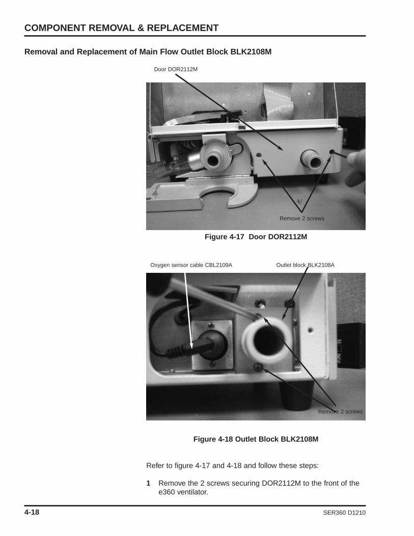
Removal and Replacement of Main Flow Outlet Block BLK2108M
Figure 4-17 Door DOR2112M
Figure 4-18 Outlet Block BLK2108M
Refer to figure 4-17 and 4-18 and follow these steps:
1 Remove the 2 screws securing DOR2112M to the front of the e360 ventilator.

SECTION 4
SER360 D1210 4-19
2 Remove 2 screws securing BLK2108M to the e360 ventilator.
3 Pull the BLK2108M away from the e360 ventilator and remove 2 tubes.
4 To reinstall, reverse above steps 2 and 3.
Removal and Replacement of Oxygen Sensor P/N SEN2103P
Refer to figure 4-18 and 4-19 and follow these steps.
1 Remove the Oxygen Sensor cable CBL2109A from the Oxygen Sensor P/N SEN2103P by unscrewing the connector on the cable.
2 Remove the Oxygen Sensor by pulling the oxygen sensor out.
Note: On older model e360 ventilators, the oxygen sensor may bescrewed in, if so, to remove, turn counter clock wise to remove.
3 To reinstall, reverse above steps 1 and 2.
Figure 4-19

Removal and Replacement of Inhalation Outlet Block and Mixing Block Assembly
Figure 4-20 Inhalation Outlet block and mixing block
Refer to figure 4-20 and follow these steps:
1 Perform above steps for removal of Oxygen Sensor P/N SEN2103P.
2 Remove 2 screws on top of mixing block BLK2107M.
3 Remove both the mixing block and inhalation block from the e360 ventilator.
4 Remove 2 screws and washers securing mixing block BLK2107M to inhalation outlet block BLK2119M and separate the two.
5 To reinstall, reverse above steps 2 through 5.
COMPONENT REMOVAL & REPLACEMENT
Inhalation outlet block“A” BLK2117M
Mixing blockBLK2107M
Remove 4 screwsand washers
4-20 SER360 D1210

SECTION 4
Oxygen sensorcable CBL2109A
Green tubeXD106
Orange tubeXD107
Remove 4 screwsand washers
Flat cableCBL2118A
Blue tubeXD103
Yellow tubeXD102
Clear tubeXD105
Flow sensorcables
CBL2116A
SER360 D1210 4-21
Removal and Replacement of Analog Board PCB2104A
Figure 4-21 Analog board PCB2104A
Refer to figure 4-21 and follow these steps:
1 Perform above steps for removal of Regulator and Solenoid Assembly BKT2105A.
2 Remove 5 tubes from PCB2104A• Orange tube – exhalation valve pressure from XD107• Green tube – Exhalation valve pressure from XD106• Blue tube – Regulated oxygen pressure from XD103• Yellow tube – Regulated air pressure from XD102• Clear tube – Patient breathing circuit pressure from XD105
Note: For all transducers, the tubes are connected to the HighPressure Port connector. For transducers XD106 and XD107, thetubings are connected to the bottom ports of the transducers. Fortransducers XD102, XD103 and XD105, the tubings are connectedto the top ports of the transducers.
3 Remove flat cable CBL2118A from J401 on PCB2104A.
4 Remove oxygen sensor cable CBL2109A from J404 on PCB2104A.
5 Remove air and oxygen flow sensor cables CBL2116A from J402 and J403 on PCB2104A
6 Remove 4 screws and washers securing PCB2104A to the e360 ventilator.

COMPONENT REMOVAL & REPLACEMENT
Remove 2 screws and washers Heater HTR1200A
4-22 SER360 D1210
7 To reinstall, reverse above steps 2 through 6.
Note: If the analog board PCB2104A is replaced, the e360ventilator will need D5 calibration performed. Refer to Section 5 for the D5 calibration.
Removal and Replacement of Heater Assembly HTR2100A
Figure 4-22 Heater Assembly HTR2100A
Refer to figure 4-22 and perform these steps:
1 Perform above steps for removal of Front Panel Assembly DSP2102A
2 Remove 2 screws securing heater HTR2100A to the MNF2110A (Exhalation Manifold).
3 Remove heater cables from power supply board PCB2101A connectors J107 and J108.
4 Remove the heater HTR2100A.
5 To reinstall, reverse above steps 2 through 5

SECTION 4
Bumper BMP2100P Remove 3 screws
SER360 D1210 4-23
Removal and Replacement of Exhalation Manifold MNF2110A
Refer to figures 4-23 and 4-24 and follow these steps:
1 Turn the e360 ventilator so the bottom of the unit is facing upward, remove 3 screws securing the MNF2110A to the baseof the e360 and the 1 screw and washer securing the bumper BMP2100P to the bottom of the e360 ventilator.
2 Remove the exhalation valve drive line and the Machine 2 pressure line from the rear of the Exhalation Manifold MNF2110A (see figure 4-22).
3 Remove the MNF2110A from the e360 ventilator.
4 To reinstall, reverse above steps 2 and 3.
Figure 4-23 Location of 3 screws and bumper
COMPONENT REMOVAL & REPLACEMENT
Exhalation valve drive line Machine 2 pressure line
4-24 SER360 D1210
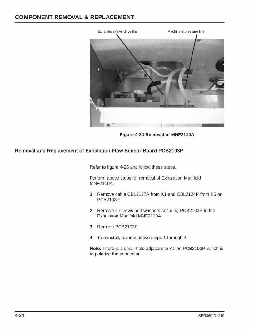
Figure 4-24 Removal of MNF2110A
Removal and Replacement of Exhalation Flow Sensor Board PCB2103P
Refer to figure 4-25 and follow these steps.
Perform above steps for removal of Exhalation ManifoldMNF2110A.
1 Remove cable CBL2127A from K1 and CBL2124P from K5 on PCB2103P.
2 Remove 2 screws and washers securing PCB2103P to the Exhalation Manifold MNF2110A.
3 Remove PCB2103P.
4 To reinstall, reverse above steps 1 through 4.
Note: There is a small hole adjacent to K1 on PCB2103P, which isto polarize the connector.

Figure 4-25 Exhalation Flow Sensor Board PCB2103P
Removal and Replacement of Battery BAT2100A
Figure 4-26 Battery removal BAT2100A
Refer to Figure 4-26 and perform these steps:
1 Perform steps for removal of Top Cover on Page 4-3.
2 Remove the battery wires from the positive and negative terminals.
3 Remove the screw securing the battery bracket to the e360 ventilator and lift off bracket.
4 Remove the battery by lifting up and out.
5 To reinstall, reverse steps 2 through 4.
SECTION 4
CBL2124P connected toK5 on PCB2103P
CBL2122A connected toK1 on PCB2103P
Polarization hole for K1on PCB2103P
SER360 D1210 4-25

COMPONENT REMOVAL & REPLACEMENT
Cable CBL2115connected to TB1
Remove 4 screwsand washers
Cable CBL2103connected to TB2
4-26 SER360 D1210
Removal and Replacement of AC/DC Power Supply PWR2100P
Figure 4-27 AC/DC Power Supply PWR2100P
Refer to figure 4-27 and follows these steps:
1 Perform above steps for removal of the battery.
2 Removal cables CBL2115A from connector TB1 and CBL2103A from connector TB2 on PWR2100P
3 Remove 4 screws and washers securing PWR2100P to the e360 ventilator.
4 Remove the PWR2100P.
5 To reinstall, reverse above steps 2 through 4.

SECTION 4
CBL2103A at J104 CBL2111A at J101 CBL2101A at J103 CN1 on PCB2106P
Remove 4 screwsand washers
CBL2108A at J106
CBL2119A at J102
SER360 D1210 4-27
Removal and Replacement of DC to DC Power Supply PCB2101A
Figure 4-28 DC to DC power supply PCB2101A
Refer to figure 4-28 and follow steps:
1 Perform above steps for removal of battery BAT2100A.
2 Remove cables from the following locations;• CBL2101A from J103 on PCB2101A• CBL2103A from J104 on PCB2101A• CBL2135A from J101 on PCB2101A• CBL2119A from J102 on PCB2101A• CBL2127A from J106 on PCB2101A• White and Black cables from J107 and J108 on PCB2101A• CBL2126A from J8 on PCB2101A
3 Remove 4 screws and washers securing PCB2101A to the e360 ventilator.
4 To reinstall, reverse above steps 2 and 3.

Removal and Replacement of Sound Processor Board PCB2106P
Refer to figure 4-28 and follow these steps:
1 Perform above steps for removal of the battery.
2 Remove flat ribbon cable from CN1 on PCB2106P
3 Remove CBL2133A from J4 on PCB2106P
4 Remove CBL2120A from J5 on PCB2106P
5 Remove 2 screws and washers securing PCB2106P to the e360 ventilator
6 Remove the board.
7 To reinstall, reverse above steps 2 through 6.
Removal and Replacement of Single Board Computer SBC2100P
Figure 4-29 Single Board Computer SBC2100P
Refer to figure 4-29 and follow these steps:
1 Perform above steps for removal of battery.
2 Remove cables from the following locations:
Cable CBL2108Ato power connector
Cable CBL2112A totouch screen
connector
Cable CBL2105Ato LCD connector Cable CBL2104A
to VGA connector
Cable CBL2114Ato USB connector
Cable CBL2112A totouch screenconnector
COMPONENT REMOVAL & REPLACEMENT
Remove 4 screwsand washers, 1 ineach corner ofPCB2100P
4-28 SER360 D1210

SECTION 4
SER360 D1210 4-29
• CBL2104A from VGA connector on SBC2100P• CBL2105A from LCD1 connector on SBC2100P• CBL2136A from Power connector on SBC2100P• CBL2112A from Touch Screen connector 3 wires on
SBC2100P• CBL2112A from Touch Screen connector 2 wires on
SBC2100P• CBL2114A from USB connector on SBC2100P
3 Remove 4 screws and washers securing SBC2100P to the e360 ventilator.
4 Remove the SBC2100P.
5 To reinstall, reverse steps 2 through 4.
Note: Cable CBL2112A splits to two connectors: 5-pin connectorwith 2 wires and 6-pin connector with 3 wires. Ensure the 3 wiresface toward the closest edge of the SBC2100P when connectingthe 6-pin connector on SBC2100P.
Note: When replacing the SBC2100P, it is necessary to removethe RAM card P/N RAM2128 and the CF card P/N CF2105A fromthe original SBC2100P and install it on the new SBC2100P. Thereplacement SBC2100P boards do not come with these partsinstalled.
Removal and Replacement of Power Sequence Board PCB2107A
1 Perform above steps for removal of battery.
2 Disconnect CBL2136A from J302 on Power Sequence Board.
3 Disconnect CBL2133A from J303 on Power Sequence Board.
4 Disconnect CBL2111A from J201 on Power Sequence Board.
5 Disconnect CBL2135A from J202 on Power Sequence Board .
6 Remove 2 Screws securing PCB2107A to side of e360 and remove board.
7 To reinstall, reverse steps 2 through 6.

5. CALIBRATION PROCEDURES
Calibration Procedures ........................................ 5-1– Calibration Equipment ................................ 5-1
Setup .................................................................... 5-2Diagnostic Mode .................................................. 5-3
– Entering Diagnostic Mode............................ 5-3Analog PCB Calibration ...................................... 5-4e360 Pneumatics Calibration .............................. 5-9
– Air Inlet Regulator ........................................ 5-9– Oxygen Inlet Regulator ................................ 5-11– Exhalation Servo Regulator ........................ 5-11– Safety Regulator .......................................... 5-12– Air Servo Valve ............................................ 5-12– Oxygen Servo Valve .................................... 5-13– Exhalation Flow Sensor .............................. 5-14– Exhalation Servo Valve ................................ 5-14
Descriptions of Message ID ................................ 5-15
SER360 D1210


SECTION 5
SER360 D1210 5-1
CALIBRATION PROCEDURES
The purpose of these procedures is to provide instructions andacceptance/rejection criteria to calibrate the e360 Ventilator.
This section describes how to use the e360 Ventilator’s DiagnosticMode to calibrate the e360 ventilator. The Diagnostic Mode canalso be used for troubleshooting (see Section 3 for moreinformation on troubleshooting).
WARNING An authorized Newport Medical Instruments factory-trained service technician must perform all service and repairson the e360 Ventilator.
WARNING Hazardous voltages are present inside the e360ventilator. Disconnect electrical power, air, and oxygen sourcesbefore attempting any disassembly. Failure to do so couldresult in injury to service personnel or damage to equipment.
NOTE: To prevent damage from ESD and possible failure of thee360 ventilator, ALWAYS use standard anti-static practices whenworking inside the e360 ventilator, handling circuit boards orhandling any other electronic components.
Calibration Equipment
Verify that all test equipment is in current calibration status. Tocalibrate the e360 Ventilator you will need the following:
• NMI Reusable Breathing Circuit (PBC340A) or equivalent
• Cap to plug the end of the breathing circuit (CAP100P) or equivalent
• Clean, dry regulated medical air and oxygen supplies at 50±2 psig.
NOTE: To perform the calibration procedures correctly, the gassupply pressure must be regulated to 50 ±2 psig. The gas suppliescan support a minimum constant flow of 180L/min.
• Power Source of 100 – 240VAC, 50/60 Hz.
• High Pressure Gauge for reading from 0 – 60 psig, or equivalent.
• Low Pressure Gauge for reading from 0 – 200 cmH2O, or equivalent.
• Pressure syringe; NMI tool (TOL1952P) or equivalent.
CALIBRATION PROCEDURES
Oxygen Supply
Air Supply
5-2 SER360 D1210
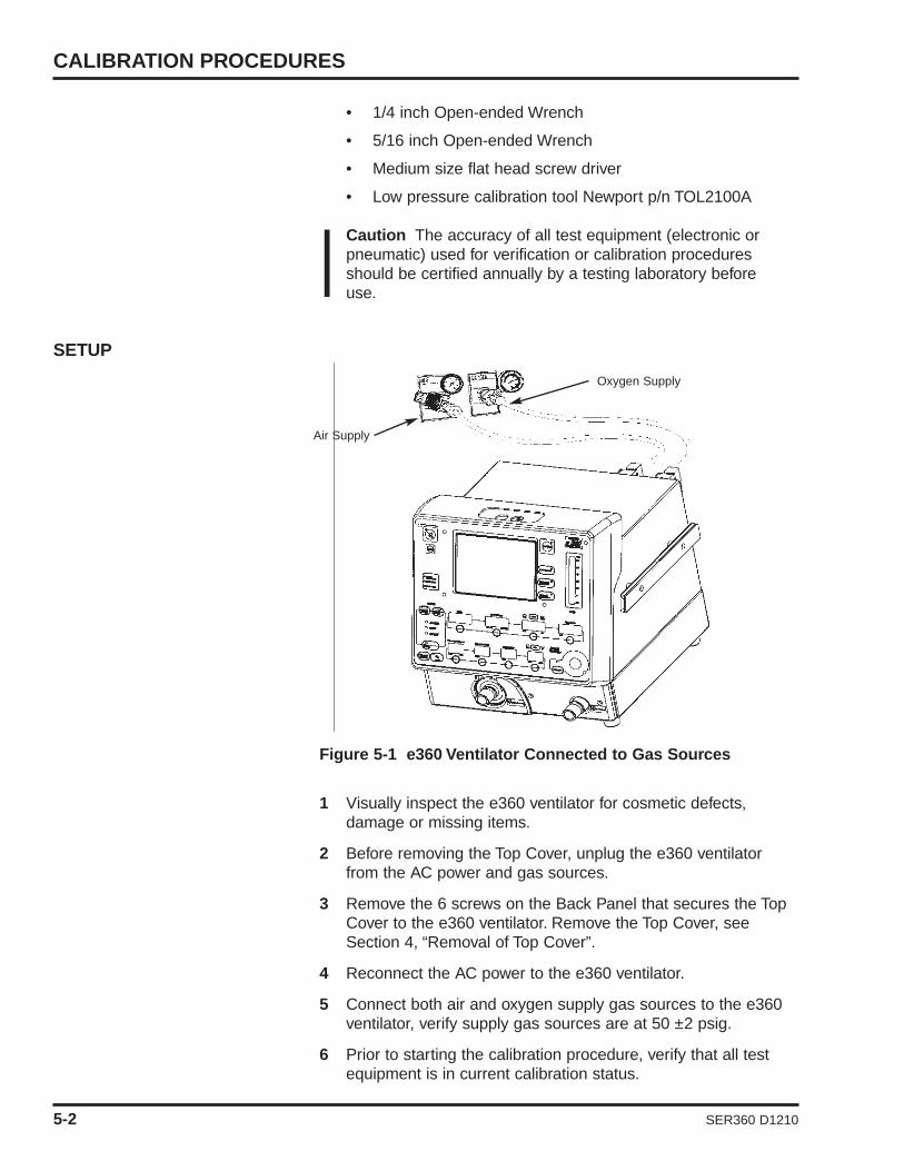
• 1/4 inch Open-ended Wrench
• 5/16 inch Open-ended Wrench
• Medium size flat head screw driver
• Low pressure calibration tool Newport p/n TOL2100A
Caution The accuracy of all test equipment (electronic or pneumatic) used for verification or calibration procedures should be certified annually by a testing laboratory before use.
SETUP
Figure 5-1 e360 Ventilator Connected to Gas Sources
1 Visually inspect the e360 ventilator for cosmetic defects, damage or missing items.
2 Before removing the Top Cover, unplug the e360 ventilator from the AC power and gas sources.
3 Remove the 6 screws on the Back Panel that secures the Top Cover to the e360 ventilator. Remove the Top Cover, see Section 4, “Removal of Top Cover”.
4 Reconnect the AC power to the e360 ventilator.
5 Connect both air and oxygen supply gas sources to the e360 ventilator, verify supply gas sources are at 50 ±2 psig.
6 Prior to starting the calibration procedure, verify that all test equipment is in current calibration status.

SECTION 5
Diagnostic Mode Calibration
D0 N/A
D1 Air Servo Valve Calibration
D2 Oxygen Servo Valve Calibration
D3 Manual Flow Adjustment
D4 Exhalation Servo Valve Calibration
D5 Analog PCB Calibration
D6 N/A
D7 N/A
D8 N/A
D9 Exhalation Flow Sensor Calibration
Table 5-1 Diagnostic Mode
SER360 D1210 5-3
Diagnostic ModeMost of the calibrations on the e360 ventilator are performed in theDiagnostic Mode. The Diagnostic Mode enables you to performServo Valve Calibration, Exhalation Valve Calibration, andRegulator Calibration.
Entering Diagnostic Mode
To enter Diagnostic Mode use the following instructions:
1 Confirm the e360 ventilator is OFF and connected to AC power.
2 Press and hold the “Accept” button and turn ON the power.
3 Release the “Accept” button when NMI Logo Screen is displayed.
4 Wait for few minutes until the Software Download/Diagnostics Mode Screen is displayed, see Figure 2-11.
5 Press “Start Diagnostics” on the LCD touch screen, see Figure 2-11. After short beeps, Diagnostic Data Screen will be displayed.
PROCEDURES .
Most calibrations rely on the Analog PCB being accuratelycalibrated first. The Analog PCB has five (5) Transducers and eachone must be calibrated according to the procedure in this Section.After the Analog PCB has been properly calibrated, proceed withthe rest of the calibrations.
To perform the calibrations successfully, it is very important thatthe air and oxygen gas supply are regulated to 50 ±2 psig and that

CALIBRATION PROCEDURES
5-4 SER360 D1210
the supply is capable of supporting a minimum of 180 L/min ofconstant flow.
Attach the patient circuit to the e360 ventilator.
NOTE: Observe ESD precautions throughout the followingprocedures for Analog PCB and Pneumatics Calibrations:
Analog PCB Calibration: d5
To locate the transducers on the Analog PCB, see Figure 5-2, below.
1 “d0” will be displayed in the “Trig” window on the Control Panel and “0” will be displayed in the “Flow/t Insp” window when the e360 ventilator enters into the Diagnostics Mode.
2 Press the button below the “Trig” window, then the display will start blinking.
3 While the display is blinking, turn the Adjustment Knob to change the setting from “d0” to “d5”. Then press the “Accept” button to acknowledge.
NOTE: Steps 4 to 14 are to calibrate zero pressure offset of the Exhalation drive pressure transducer XD107.
NOTE: Reference table 5-2 for tubing, transducer and zeropressure offset values.
4 Remove the ORANGE tubing from transducer XD107 on the Analog PCB.
5 Set Respiratory Rate to 128.
6 Press the “Manual Inflation” button to start the offsetcalibration. The Message at the bottom of the LCD will be“Start Calibration”.
7 Verify the setting of “t Insp” is “0”. If not, press the button below “Flow / t Insp” window, then the display will start blinking.
8 While the display is blinking, turn the Adjustment Knob toadjust the setting of “t Insp” to “0”, and then press the“Accept” button to acknowledge.
9 Press the button below “Resp Rate” window, then the display will start blinking.
10 While the display is blinking, turn the Adjustment Knob to change the setting to any value, and then press the “Accept”button to acknowledge.
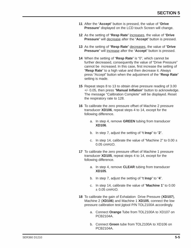
SECTION 5
SER360 D1210 5-5
11 After the “Accept” button is pressed, the value of “Drive Pressure” displayed on the LCD touch Screen will change.
12 As the setting of “Resp Rate” increases, the value of “Drive Pressure” will decrease after the “Accept” button is pressed.
13 As the setting of “Resp Rate” decreases, the value of “Drive Pressure” will increase after the “Accept” button is pressed.
14 When the setting of “Resp Rate” is “0”, which cannot be further decreased, consequently the value of “Drive Pressure”cannot be increased. In this case, first increase the setting of “Resp Rate” to a high value and then decrease it. Always press “Accept” button when the adjustment of the “Resp Rate”setting is made.
15 Repeat steps 8 to 13 to obtain drive pressure reading of 3.00 +/- 0.05, then press "Manual Inflation" button to acknowledge.The message "Calibration Complete" will be displayed. Reset the respiratory rate to 128.
16 To calibrate the zero pressure offset of Machine 2 pressure transducer XD106, repeat steps 4 to 14, except for the following difference.
a. In step 4, remove GREEN tubing from transducer XD106.
b. In step 7, adjust the setting of “t Insp” to “2”.
c. In step 14, calibrate the value of “Machine 2” to 0.00 ±0.05 cmH2O.
17 To calibrate the zero pressure offset of Machine 1 pressure transducer XD105, repeat steps 4 to 14, except for the following difference.
a. In step 4, remove CLEAR tubing from transducer XD105.
b. In step 7, adjust the setting of “t Insp” to “4”.
c. In step 14, calibrate the value of “Machine 1” to 0.00 ± 0.05 cmH2O.
18 To calibrate the gain of Exhalation Drive Pressure (XD107),Machine 2 (XD106) and Machine 1 XD105, connect the lowpressure calibration test jigtool P/N TOL2100A accordingly.
a. Connect Orange Tube from TOL2100A to XD107 on PCB2104A.
b. Connect Green tube from TOL2100A to XD106 on PCB2104A.

CALIBRATION PROCEDURES
5-6 SER360 D1210
c. Connect Clear tube from TOL2100A to XD105 on PCB2104A.
d. Connect one of the large ID clear tubes to a calibratedpressure gauge and connect the other large ID cleartube to the pressure syringe P/N TOL1952P.
Note: Reference table 5-3 for tubing, transducer and pressure gainvalues.
Note: If pressure is only applied to transducer XD105 during thiscalibration, Device Alert will occur when the pressure to XD105 is20cmH2O higher than the pressure to XD106. Device Alert can beonly cleared by turning OFF and ON the e360 ventilator.
19 Adjust the pressure syringe so that 110 cmH2O is displayed on the calibrated pressure gauge.
20 Adjust “t Insp” to “1” (Drive Pressure) and press themanual inflation button, the message at the bottom of the LCDwill change to calibrating.
21 Press the button below “Resp Rate” window, then the display will start blinking.
22 While the display is blinking, turn the Adjustment Knob to change the setting to any value, and then press the “Accept”button to acknowledge.
23 After the “Accept” button is pressed, the value of “Drive Pressure” displayed on the LCD touch Screen will change.
24 Repeat steps 21 and 22 to obtain drive pressure of 110.00cmH2O ± 1.0 cmH2O, then press “Manual Inflation” button toacknowledge. The Message “calibration complete” will bedisplayed at the bottom of the LCD. Reset the respiratory rateto 128.
25 Set “t Insp” to 3 (Machine 2) and press the manual inflation button.
26 Repeat steps 21 and 22 to obtain drive pressure of 110.00cmH2O ± 1.0 cmH2O, then press “Manual Inflation” button toacknowledge. The Message “calibration complete” will bedisplayed at the bottom of the LCD. Reset the respiratory rateto 128.
27 Set “t Insp” to 5 (Machine 1) and press the manual inflation button.
28 Repeat steps 21 and 22 to obtain drive pressure of 110.00cmH2O ± 1.0 cmH2O, then press “Manual Inflation” button toacknowledge. The Message “calibration complete” will be dis-

SECTION 5
SER360 D1210 5-7
played at the bottom of the LCD. Reset the respiratory rate to128.
29 Disconnect the low pressure calibration tool p/n TOL2100Afrom the analog aboard and reconnect the tubes from insidethe e360.
• Orange tube -> XD107• Green tube -> XD106• Clear tube -> XD105
30 Using the same method as above, calibrate the zero pressureoffset of Air Gas Supply pressure transducer XD102.
a. Remove YELLOW tubing from transducer XXD102.
b. Adjust the setting of “t Insp” to “6”.
c. Calibrate the value of “Air Gas Supply” to 0.0 + 0.1 psig.
31 Using the same method as above, calibrate the gain of Air GasSupply pressure transducer XD102.
a. Adjust the setting of “t Insp” to “7”.
b. Tee in a calibrated pressure gauge and apply a pressure of 25 psig to the top port of transducer XD102.
c. Using the setting for Resp Rate calibrate the value of “Air Gas Supply” to 25.0 ± 0.1 psig.
d. Connect YELLOW tubing back to the top port of transducer XD102.
32 Using the same method as above, calibrate the zero pressure offset of Oxygen Gas Supply pressure transducer XD103.
a. Remove BLUE tubing from transducer XD103.
b. Adjust the setting of “t Insp” to “8”.
c. Calibrate the value of “Oxygen Gas Supply” to 0.0 + 0.1 psig.
33 Using the same method as above, calibrate the gain of Oxygen Gas Supply pressure transducer XD103.
a. Adjust the setting of “t Insp” to “9”.
b. Tee in a calibrated pressure gauge and apply a pressure of 25 psig to the top port of transducer XD103.

CALIBRATION PROCEDURES
5-8 SER360 D1210
c. Calibrate the value of “Oxygen Gas Supply” to 25.0 ±0.1 psig.
d. Connect BLUE tubing back to the top port of transducer XD103.
34 Turn OFF the power, and then disconnect the Air and O2 gas supplies and AC power.
Figure 5-2 Analog PCB
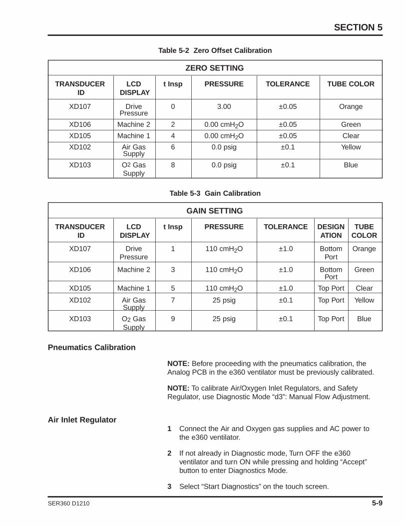
SECTION 5
TRANSDUCER LCD t Insp PRESSURE TOLERANCE TUBE COLORID DISPLAY
XD107 Drive 0 3.00 ±0.05 OrangePressure
XD106 Machine 2 2 0.00 cmH2O ±0.05 Green
XD105 Machine 1 4 0.00 cmH2O ±0.05 Clear
XD102 Air Gas 6 0.0 psig ±0.1 YellowSupply
XD103 O2 Gas 8 0.0 psig ±0.1 BlueSupply
ZERO SETTING
Table 5-2 Zero Offset Calibration
TRANSDUCER LCD t Insp PRESSURE TOLERANCE DESIGN TUBE ID DISPLAY ATION COLOR
XD107 Drive 1 110 cmH2O ±1.0 Bottom OrangePressure Port
XD106 Machine 2 3 110 cmH2O ±1.0 Bottom GreenPort
XD105 Machine 1 5 110 cmH2O ±1.0 Top Port Clear
XD102 Air Gas 7 25 psig ±0.1 Top Port YellowSupply
XD103 O2 Gas 9 25 psig ±0.1 Top Port BlueSupply
GAIN SETTING
Table 5-3 Gain Calibration
SER360 D1210 5-9
Pneumatics Calibration
NOTE: Before proceeding with the pneumatics calibration, theAnalog PCB in the e360 ventilator must be previously calibrated.
NOTE: To calibrate Air/Oxygen Inlet Regulators, and SafetyRegulator, use Diagnostic Mode “d3”: Manual Flow Adjustment.
Air Inlet Regulator1 Connect the Air and Oxygen gas supplies and AC power to
the e360 ventilator.
2 If not already in Diagnostic mode, Turn OFF the e360 ventilator and turn ON while pressing and holding “Accept”button to enter Diagnostics Mode.
3 Select “Start Diagnostics” on the touch screen.
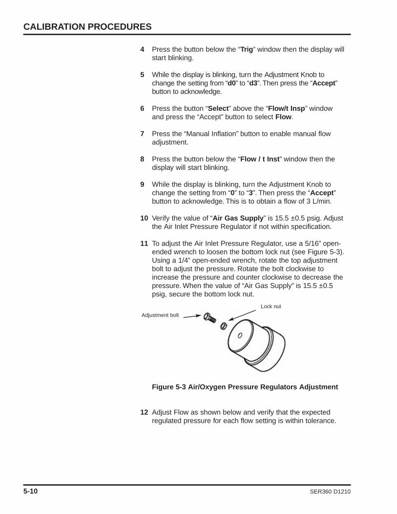
4 Press the button below the “Trig” window then the display will start blinking.
5 While the display is blinking, turn the Adjustment Knob to change the setting from “d0” to “d3”. Then press the “Accept”button to acknowledge.
6 Press the button “Select” above the “Flow/t Insp” window and press the “Accept” button to select Flow.
7 Press the “Manual Inflation” button to enable manual flow adjustment.
8 Press the button below the “Flow / t Inst” window then the display will start blinking.
9 While the display is blinking, turn the Adjustment Knob to change the setting from “0” to “3”. Then press the “Accept”button to acknowledge. This is to obtain a flow of 3 L/min.
10 Verify the value of “Air Gas Supply” is 15.5 ±0.5 psig. Adjust the Air Inlet Pressure Regulator if not within specification.
11 To adjust the Air Inlet Pressure Regulator, use a 5/16” open-ended wrench to loosen the bottom lock nut (see Figure 5-3).Using a 1/4” open-ended wrench, rotate the top adjustment bolt to adjust the pressure. Rotate the bolt clockwise to increase the pressure and counter clockwise to decrease the pressure. When the value of “Air Gas Supply” is 15.5 ±0.5 psig, secure the bottom lock nut.
Figure 5-3 Air/Oxygen Pressure Regulators Adjustment
12 Adjust Flow as shown below and verify that the expected regulated pressure for each flow setting is within tolerance.
CALIBRATION PROCEDURES
Lock nut
Adjustment bolt
5-10 SER360 D1210

SECTION 5
Flow Setting Oxygen Inlet Pressure
3 L/min 15.0 to 16.0 psig
100 L/min 12.0 to 14.5 psig
180 L/min > 9.5 psig
Flow Setting Air Inlet Pressure
3 L/min 15.0 to 16.0 psig
100 L/min 12.0 to 14.5 psig
180 L/min > 9.5 psig
SER360 D1210 5-11
Table 5-4 Air Flow and Pressure Settings
Oxygen Inlet Regulator1 While still in Diagnostic Mode “d3”, adjust FIO2 to 100%
oxygen and adjust Flow to 3 L/min.
2 Adjust the oxygen inlet regulator pressure to 15.5 ±0.5 psig.
3 To adjust the Oxygen Inlet Pressure Regulator, refer to the above “Air Inlet Regulator”, step 9.
4 Adjust Flow as shown below and verify that the expected regulated pressure for each flow setting is within tolerance.
Table-5-5 Oxygen Flow and Pressure Settings
5 Adjust Flow to 0 L/min and FIO2 to 21% after the calibration is completed.
Exhalation Servo Regulator
1 Take the ORANGE tubing from the Exhalation Servo Valve port “IN” and connect to a calibrated high pressure gauge, seeFigure 5-4.
2 Use a flat head screw driver to adjust the Exhalation Servo Regulator, which is located near the Exhalation Servo Valve, between 15.0 and 15.5 psig.
3 Reconnect the ORANGE tubing to the Exhalation Servo Valve port “IN”.

Figure 5-4 Exhalation Servo / Safety Regulators
Safety Regulator
1 While still in Diagnostics Mode “d3”, adjust Flow to 3 L/min.
2 Connect a patient circuit to the e360 ventilator as shown in Figure 6-1. (Test lung is not needed)
3 Disconnect the patient circuit from the Exhalation Valve, and connect it to the Y-piece of the patient circuit, which is to form a close loop.
4 Tee in a low pressure gauge in the patient circuit.
5 Use a flat head screw driver to adjust the Safety Regulator, see Figure 5-4, to obtain 140 ± 5 cmH2O of “Machine 1”pressure displayed on LCD touch screen.
6 Adjust Flow to 0 L/min after the calibration is completed. Then press “Manual Inflation” button to disable manual flow adjustment.
Air Servo Valve: d1
Caution: Do not attempt to perform Air Servo Valve calibrationunless instructed by NMI Representative or for one of thefollowing conditions:•Replacement or readjustment of Air Inlet Regulator •Replacement of Air Servo Valve•Replacement of Analog PCB•Replacement of Main PCB
CALIBRATION PROCEDURES
OrangeTubing toExh. ServoVal. Port “IN”
Exh. Servo Val.
Exh. ServoRegulator
SafetyRegulator
5-12 SER360 D1210

Caution: Do not attempt to perform Air Servo Valve calibrationunless the air gas supply is regulated to 50 ± 2 psig and capableof supporting a minimum of 180 L/min of constant flow.
1 Set the e360 ventilator to Diagnostics Mode “d1”.
2 Disconnect the patient circuit from the e360 ventilator.
3 Press the “Manual Inflation” button to initiate Air Servo Valve calibration. The e360 ventilator will go through a calibration maneuver that slowly increases and then decreases flow twice.
4 The value of “TSI Air Flow” displayed on LCD touch screen will slowly change as the delivered flow changes.
5 Wait for several minutes to complete the calibration until the “Message Test Complete” is displayed on the LCD.
Note: If the “Message Calibration Failed: Valve Leaks more than50 cc is displayed after the D1 is completed, then the servo valveneeds to be replaced.
Oxygen Servo Valve: d2
Caution: Do not attempt to perform Oxygen Servo Valvecalibration unless instructed by a NMI Representative or for oneof the following conditions:•Replacement or readjustment of Oxygen Inlet Regulator •Replacement of Oxygen Servo Valve•Replacement of Analog PCB•Replacement of Main PCB
Caution: Do not attempt to perform Oxygen Servo Valvecalibration unless the oxygen gas supply is regulated to 50 ± 2psig and capable of supporting a minimum of 180 L/min ofconstant flow.
1 Set the e360 ventilator to Diagnostics Mode “d2”.
2 Disconnect the patient circuit from the e360 ventilator.
3 Press the “Manual Inflation” button to initiate Oxygen Servo Valve calibration. The e360 ventilator will go through a calibration maneuver that slowly increases and then decreases flow twice.
4 The value of “TSI O2 Flow” displayed on LCD touch screen will slowly change as the delivered flow changes.
5 Wait for several minutes to complete the calibration until the “Message Test Complete” is displayed on the LCD.
Note: If the Message Calibration Failed: Valve Leaks more than 50cc is displayed after the D2 calibration is completed, then theservo valve needs to be replaced.
SECTION 5
SER360 D1210 5-13
Exhalation Flow Sensor: d9
1 Turn OFF the e360 ventilator.
2 Turn ON the e360 ventilator and wait until the “Ventilation Standby” screen is displayed.
3 Connect the patient circuit to the e360 ventilator as shown in Figure 6-1.
4 Occlude the patient circuit at the Y-piece using a cap. A filter and test lung is not required for this calibration.
5 Press “CIRCUIT CHECK” on LCD touch screen to perform the circuit check. Confirm that the circuit check passes.
6 Press “SENSORS” on LCD touch screen, and press “Flow Sensor” to start Exhalation Flow Sensor calibration. It may require performing several times in order to pass the Exhalation Flow Sensor calibration.
7 Turn OFF the e360 ventilator and turn ON while pressing and holding “Accept” button to enter Diagnostics Mode.
8 Set the e360 ventilator to Diagnostics Mode “d9”.
9 With patient circuit occluded, press “Manual Inflation” button to start Exhalation Flow Sensor calibration in Diagnostics Mode.
10 Wait for several minutes to complete the calibration until themessage “Test Complete” is displayed on the LCD..
Exhalation Servo Valve: d4
1 Set the e360 ventilator to Diagnostics Mode “d4”.
2 With patient circuit occluded, press the “Manual Inflation”button once. The Message “Occlude the circuit”.
3 Press the “Manual Inflation” button again to start the calibration.
4 Wait for several minutes to complete the calibration until the message “Test Complete” is displayed on the LCD.
5-14 SER360 D1210
CALIBRATION PROCEDURES

SER360 D1210
6. OPERATIONAL VERIFICATIONPROCEDURE
Operational Verification Procedure ...................... 6-1 Test Equipment................................................ 6-1
Setup .................................................................... 6-2 Electrical Safety Checks ...................................... 6-2
Ground Resistance test .................................. 6-2 Current Leakage test ...................................... 6-3
Operational Checks ............................................ 6-3– Front Panel LED Check .............................. 6-4– Circuit Leak Test .......................................... 6-5– Loss of Gas Alarm ...................................... 6-5 – FIO2 Test ...................................................... 6-6– Main Flow .................................................... 6-6– Bias Flow .................................................... 6-8– Inspiratory Time............................................ 6-8– Respiratory Rate .......................................... 6-8– Pressure Control .......................................... 6-9– Pressure Support ........................................ 6-9– Pressure Trigger Sensitivity.......................... 6-9– PEEP/CPAP ................................................ 6-10 – Manual Inflation ............................................ 6-11 – Inspiratory Tidal Volume .............................. 6-11 – Expiratory Tidal Volume .............................. 6-11 – Alarm Silence .............................................. 6-12 – Loss of Power Alarm and Battery
Operation ...................................................... 6-12 e360 Operational Verification Test Record Sheet................................................ 6-13
OPERATIONAL VERIFICATION PROCEDURE
The Operational Verification Procedure ensures that the Newporte360 Ventilator is in proper operating condition.
WARNING Do not use the e360 ventilator unless it passes theOperational Verification Procedure.
Test Equipment
• Electrical safety test (EST) analyzer
• Certified calibration analyzer manufactured by TSI, Inc. orequivalent
• Oxygen Analyzer
• Newport reusable patient breathing circuit (PBC340A) orequivalent
• Adult test lung (LNG800P), or adult test lung with RP20 airway resistor (LNG600A) or equivalent
• Adjustable (0-60 psig) dry clean regulated medical grade air and oxygen gas supplies
• A cap to occlude the patient circuit Y-piece (CAP100P)or equivalent
Caution The accuracy of all test equipment (electronic orpneumatic) used for verification or calibration procedures shouldbe certified annually by a testing laboratory before use.
SECTION 6
SER360 D1210 6-1

SETUP
Figure 6-1 Test Setup
1 Connect reusable adult patient breathing circuit to the e360 ventilator to be tested. Attach a test lung to the patient breathing circuit Y-Piece.
2 Connect the calibration analyzer with oxygen sensor between the main flow outlet and the patient breathing circuit.
3 Connect regulated adjustable air and oxygen gas supplies to ventilator inlets on the back of the ventilator. Set regulators to 50 psig.
4 Make a copy of the e360 Test Record sheets provided at the end of this section. Check the appropriate box or record appropriate data on the record sheet after each test is performed.
ELECTRICAL SAFETY CHECKS
Ground Resistance Test
1 Connect the A.C. power cord to the EST analyzer.
2 Connect the ground lead of the EST analyzer to the labeled equipotential connection on the back of the ventilator.
3 Perform ground resistance check and record the results on the OVP record sheet. To pass, the ventilator ground resistance must be <0.1Ω.
OPERATIONAL VERIFICATION PROCEDURE
Y-Piece
Breathing Circuit
6-2 SER360 D1210
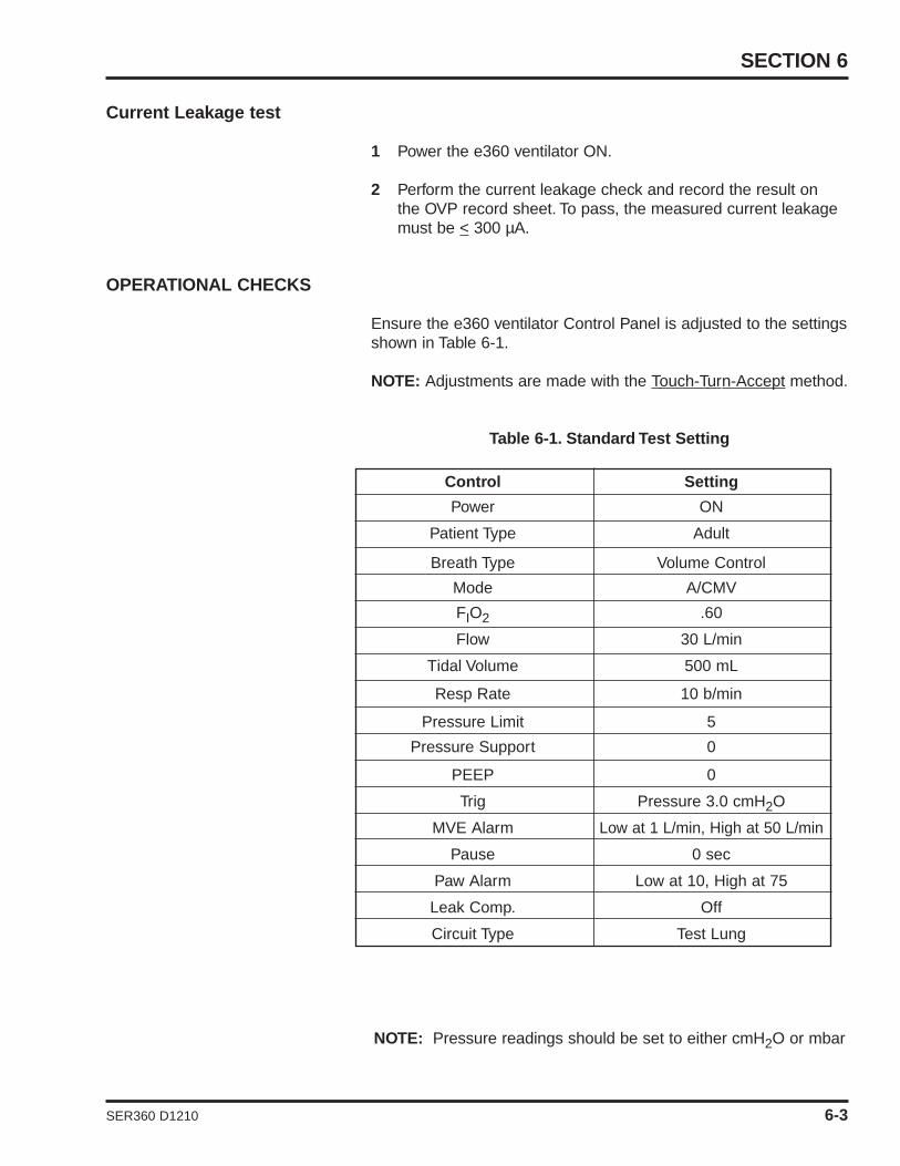
SECTION 6
Control Setting
Power ON
Patient Type Adult
Breath Type Volume Control
Mode A/CMV
FIO2 .60
Flow 30 L/min
Tidal Volume 500 mL
Resp Rate 10 b/min
Pressure Limit 5
Pressure Support 0
PEEP 0
Trig Pressure 3.0 cmH2O
MVE Alarm Low at 1 L/min, High at 50 L/min
Pause 0 sec
Paw Alarm Low at 10, High at 75
Leak Comp. Off
Circuit Type Test Lung
NOTE: Pressure readings should be set to either cmH2O or mbar
SER360 D1210 6-3
Current Leakage test
1 Power the e360 ventilator ON.
2 Perform the current leakage check and record the result on the OVP record sheet. To pass, the measured current leakage must be < 300 µA.
OPERATIONAL CHECKS
Ensure the e360 ventilator Control Panel is adjusted to the settingsshown in Table 6-1.
NOTE: Adjustments are made with the Touch-Turn-Accept method.
Table 6-1. Standard Test Setting

Front Panel LED Check
Figure 6-2 Front Panel Controls & Indicators
1 Toggle the power switch located on the back of the e360 ventilator, to the OFF position.
2 Press down the “Accept” button located next to the Adjustment Knob.
3 While pressing the “Accept” button, toggle to the ON position.This puts the e360 ventilator into Diagnostics Mode. Releasethe ”Accept“ button.
4 Verify that all the Control Panel display lights are lit except for the Alarm Lamp on top of the ventilator.
5 Power the e360 off.
6-4 SER360 D1210
OPERATIONAL VERIFICATION PROCEDURE
Manual Inflation
EncoderAdjustment Knob

Circuit Leak Test
Figure 6-3 Circuit Leak Test
NOTE: Circuit Check is available in Ventilation Standby only.
1 Remove test lung if present and occlude the end of the patient circuit Y-Piece using CAP100P.
2 Power ON the e360.
3 Press the “Circuit Check“ button on the display and follow the screen instructions.
4 After the test is completed, verify that the message display window reads PASSED. Check off the record sheet and reattach the test lung.
5 To exit Ventilation Standby condition, press the “START VENTILATING“ button on LCD touch screen.
Exhalation Flow Sensor and FiO2 Sensor Calibration
1 Press the “Sensors” button on the display..
2 Press the 'Flow Sensor” button on the display and follow the screen instructions.
3 Press the “O2 Sensor” button on the display and follow the screen instructions.
SECTION 6
SER360 D1210 6-5
Option 1
WeaningMechanic
Advanced
Basic
Option 1CircuitCheck
Sensors
TechnicalSetup
PatientSetup
MODE: VC/ACMVVentilation Standby
10-03-06 14:25
Circuit Check
2. Occlude circuit Y-piece
3. Presss Circuit Check button to begin
1. Attach complete breathing circuit
ADULT
START VENTILATING
MVEPEEPPpeak VTE RR tot--------------- ---
FIO2mL/kg

Loss of Gas Alarm
1 Set Ventilator to standard test settings (STS). Lower the air gas supply pressure to 20 psig. Verify that there is no Loss of Gas alarm.
2 Lower the air gas supply pressure to 8 psig. Verify that the audible alarm sounds, the red LED on the top is flashing, and the message display reads Air Supply Loss.
3 Set the air gas supply pressure to 50 psig, and clear the alarm.
4 Repeat steps 1-3 for the oxygen gas source.
5 Shut off both gas supplies.Verify that the audible alarm sounds, the red LED on the top is flashing, and the message display reads Both Air/O2 Supply Loss.
6 Turn on both gas supplies and clear the alarm.
FIO2 Test
1 Set the FIO2 to 0.21.
2 Verify the value of FIO2 displayed on LCD touch screen, the FIO2 reading measured by the oxygen analyzer, and the FIO2setting are within tolerance of ± 3% among each other.Record the readings on the Test Record.
3 Repeat step 1 with FIO2 settings of 0.40, 0.60, 0.80, and 1.0. , use Touch-Turn-Accept method to adjust settings.
4 Set FIO2 to 0.21.
NOTE: Allow sufficient time for the calibration analyzer to stabilizeat each setting before recording the calibration analyzer reading.
Main Flow
1 Remove the test lung from the patient circuit Y-Piece.
2 Place the calibration analyzer at the Inhalation Outlet, and set the calibration analyzer to flow measurement.
3 Press the button under the “Tidal volume“ window and use the Touch-Turn-Accept method to adjust setting to 2.00 L.
4 Press the “Select“ button at the top of the “Flow/t Insp”window to choose Flow.
5 Press “Main Screen” membrane button on control panel.
6 Press the “Numeric“ button on the LCD touch screen to display Numeric data.
OPERATIONAL VERIFICATION PROCEDURE
6-6 SER360 D1210

SECTION 6
SER360 D1210 6-7
7 Set Flow to 5 L/min, verify the value of peakI (Insp Flow) displayed on the Numeric screen, the flow reading measured by the calibration analyzer, and the flow setting are within tolerance of ± 1 L/min among each other. Record the readings on the Test Record.
8 Set Flow to 10 L/min, verify the value of peakI (Insp Flow) displayed on the Numeric screen, the flow reading measured by the calibration analyzer, and the flow setting are within tolerance of ± 1 L/min among each other. Record the readings on the Test Record.
9 Set Flow to 50 L/min, verify the value of peakI (Insp Flow) displayed on the Numeric screen, the flow reading measured by the calibration analyzer, and the flow setting are within tolerance of ± 4 L/min among each other. Record the readings on the Test Record. Record the readings on the Test Record.
10 Set Flow to 80 L/min, verify the value of peakI (Insp Flow) displayed on the Numeric screen, the flow reading measured by the calibration analyzer, and the flow setting are within tolerance of ± 5 L/min among each other. Record the readings on the Test Record.
11 Set FIO2 to 100%, and set the calibration analyzer to oxygen flow measurement.
12 Repeat steps 7 - 10. Record the reading on the Test Record.
Note: “The flow reading measured by the calibration analyzer”mentioned in steps 7-9 will be the actual delivered measurementdividing by 89%. This is because the e360 ventilator automaticallyreduces the flow delivery by 11% of the set flow to compensate forusing with a humidifier (BTPS compensation).
13 Set FIO2 to 21%, Flow to 30 L/min and VT (Tidal Volume) to 500; reattach the test lung.
NOTE: Because the e360 ventilator automatically compensates foruse with a humidifier by lowering the flow by 11% (calibrated toBTPS) the calibration analyzer flow reading will be 11% lower thanthe ventilator’s set flow rate if the calibration analyzer is not BTPScompensated.
NOTE: When peakI reading displayed on the Numeric screen ishigher than expected flow, it could be caused by the peak flowdelivered in the very beginning of the inspiratory phase. In this case,select flow waveform in the Waves screen, and then press “Freeze”button to read the actual flow value. To adjust the scale of thewaveform, touch the flow axis on the screen, turn the knob, and thentouch the flow axis again to accept when a proper scale is obtained.
V•
V•
V•
V•
V•
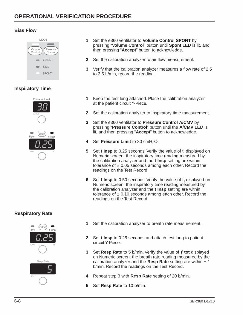
OPERATIONAL VERIFICATION PROCEDURE
6-8 SER360 D1210
Bias Flow
1 Set the e360 ventilator to Volume Control SPONT by pressing “Volume Control“ button until Spont LED is lit, and then pressing “Accept” button to acknowledge.
2 Set the calibration analyzer to air flow measurement.
3 Verify that the calibration analyzer measures a flow rate of 2.5 to 3.5 L/min, record the reading.
Inspiratory Time
1 Keep the test lung attached. Place the calibration analyzer at the patient circuit Y-Piece.
2 Set the calibration analyzer to inspiratory time measurement.
3 Set the e360 ventilator to Pressure Control A/CMV by pressing “Pressure Control” button until the A/CMV LED is lit, and then pressing “Accept” button to acknowledge.
4 Set Pressure Limit to 30 cmH2O.
5 Set t Insp to 0.25 seconds. Verify the value of tI displayed on Numeric screen, the inspiratory time reading measured by the calibration analyzer and the t Insp setting are within tolerance of ± 0.05 seconds among each other. Record the readings on the Test Record.
6 Set t Insp to 0.50 seconds. Verify the value of tI displayed on Numeric screen, the inspiratory time reading measured by the calibration analyzer and the t Insp setting are within tolerance of ± 0.10 seconds among each other. Record the readings on the Test Record.
Respiratory Rate
1 Set the calibration analyzer to breath rate measurement.
2 Set t Insp to 0.25 seconds and attach test lung to patient circuit Y-Piece.
3 Set Resp Rate to 5 b/min. Verify the value of ƒ tot displayed on Numeric screen, the breath rate reading measured by the calibration analyzer and the Resp Rate setting are within ± 1 b/min. Record the readings on the Test Record.
4 Repeat step 3 with Resp Rate setting of 20 b/min.
5 Set Resp Rate to 10 b/min.

SECTION 6
0.5
SER360 D1210 6-9
Pressure Control
1 Set the calibration analyzer to peak pressure measurement in cmH2O.
2 Set Pressure Limit to 10 cmH2O, and t Insp to 3.0 seconds.
3 Verify that the value of Ppeak displayed on Numericscreen, the peak pressure measured by the calibration analyzer and the Pressure Limit setting are within tolerance of ±10% among each other. Record the readings on the Test Record.
4 Repeat step 3 with Pressure Limit setting of 20 cmH2O.
5 Repeat step 3 with Pressure Limit setting of 50 cmH2O.
Pressure Support
1 Set the e360 ventilator to Pressure Control SPONT.
2 Set Trig to P (pressure) and adjust to 0.5 cmH2O.
3 Set Pressure Support to 10 cmH2O.
4 Squeeze the test lung to trigger a breath. Verify that the value of Ppeak displayed on Numeric screen, the peak pressure measured by the calibration analyzer and the Pressure Support setting are within tolerance of ± 10% among each other. Record the readings on the Test Record.
5 Repeat step 4 with Pressure Support for setting of 20 cmH2O.
6 Set Pressure Support to 0 cmH2O, and verify no pressure-supported breaths are delivered.
Pressure Trigger Sensitivity
1 Set Pressure Support to 10 cmH2O.
2 Set PEEP/CPAP to 7 cmH2O.
3 Set e360 Trig to P (pressure) and set to 1.0 cmH2O.

OPERATIONAL VERIFICATION PROCEDURE
3
6-10 SER360 D1210
4 Manually squeeze and slowly release the test lung to create a dip in the pressure bar graph. Verify that the dip equals the P Trig setting when a pressure support breath is triggered.
5 Repeat step 4 with Ptrig setting of 3 cmH2O.
6 Set Pressure Support to 0 cmH2O. Leave the test lung connected, and proceed to the next test.
PEEP/CPAP
1 Set the e360 ventilator to the standard test settings except for PEEP to 3 cmH2O. Set the calibration analyzer to PEEPmeasurement.
2 Verify that the value of PEEP displayed on Numeric touch screen, the pressure reading measured by the calibration analyzer, the pressure bar graph on the Control Panel, and thePEEP/CPAP setting are within tolerance of ± 1 cmH2O among each other. Record readings on the e360 Test Record.
3 Repeat step 2 with PEEP setting of 10 cmH2O.
4 Set Low Paw alarm to 20 cmH2O, and repeat step 2 with PEEP setting of 20 cmH2O.
NOTE: Allow three to four breaths at each setting for pressure tostabilize.
5 Set the PEEP to 0 cmH2O and set Low Paw alarm to 10 cmH2O.

SECTION 6
SER360 D1210 6-11
Manual Inflation
1 Set the e360 ventilator to Volume Control SPONT.
2 Press the “Manual Inflation” button.
3 Verify that a manual inflation is delivered while the button is pressed.
Inspiratory Tidal Volume
1 Set the e360 ventilator to Volume Control A/CMV.
2 Set Flow to 30 L/min.
3 Press “Main Screen” button on the Control Panel, and then press “Numeric” button on the LCD touch screen.
4 Set the calibration analyzer to volume measurement in BTPS mode, and connect it in the inspiratory limb of the patient circuit.
5 Set Tidal Volume to 200 mL. Verify the value of VTI displayed on Numeric screen, the tidal volume reading measured by the calibration analyzer and the Tidal Volume setting are within tolerance of ± 10% among each other. Record readings on the Test Record.
6 Repeat step 5 with Tidal Volume settings of 500 mL, and 1L.
Expiratory Tidal Volume
1 Connect the calibration analyzer at the patient wye of the patient circuit.

2 Set Tidal Volume to 250 mL. Verify that the value of VTE displayed on Numeric screen is between 225 – 275 mL, and verify that the tidal volume reading measured by the calibration analyzer and the Tidal Volume setting are within tolerance of +10%. Record readings on the Test Record.
3 Set Tidal Volume to 500 mL. Verify that the value of VTE displayed on Numeric screen is between 450 – 550 mL, and verify that the tidal volume reading measured by the calibration analyzer and the Tidal Volume setting are within tolerance of +10%. Record readings on the Test Record.
4 Set Tidal Volume to 1.00 L. Verify that the value of VTE displayed on Numeric screen is between 900 mL – 1.1 L, and verify that the tidal volume reading measured by the calibration analyzer and the Tidal Volume setting are within tolerance of +10%. Record readings on the Test Record.
Alarm Silence
1 Create an alarm condition by changing the settings and wait for the alarm to sound.
2 Press the “Alarm Silence” button and verify the indicator lights up, and the audible alarm stops.
3 Press the “Alarm Silence” button again and verify the indicator turns off, and the audible alarm resumes.
4 Return e360 ventilator to standard test setting. Press Resetbutton to clear alarm indicators.
5 Check off on the record sheet.
Loss of Power Alarm and Battery Operation
1 Disconnect the power cord from the AC power source.
2 Verify that the messages AC Power Loss and Battery Back Up are displayed in the message window. Verify that the audible alarm sounds and the Internal Battery indicator lights.
3 Verify that at least 3 bars of the charge bar graph are lit.
4 Reconnect the power cord to the AC power source.
Note: To ensure that the internal battery remains functional, fullyrecharge the battery at least every 3 months when the e360 is notin use.
6-12 SER360 D1210
OPERATIONAL VERIFICATION PROCEDURE

SER360 D1210 6-13
SECTION 6
e360 OVP TEST RECORD SHEET
Hospital or Organization ______________________________________________________________
e360 Serial Number ___________________ Hour Meter ________ Software Rev.____________
Service Technician ________________________________________Date __________________
Released by ____________________________________________
Test Equipment: ID No. Electrical Safety Tol. Value Test
Calibration Analyzer Ground resistance <0.1ΩOxygen Analyzer Max leakage current <300 µA
Electrical Safety Analyzer
FIO2
Test Pass Set Displayed Measured Tol. RangeFI02 FI02
Front Panel Visual LED Check 21 + 3 Variance
Pneumatic Leak Test 40 + 3 Variance
Loss of Gas Alarms (Air/O2 ) 60 + 3 Variance
FIO2 80 + 3 Variance
Main Flow 100 + 3 Variance
Bias Flow Main Flow (L/min) FIO2 = 21%
Inspiratory time Set peakI Measured Tol. RangeFlow/89%
Respiratory Rate 5 + 1 Variance
Pressure Control 10 + 1 Variance
Pressure Support 50 + 4 Variance
Ptrig sensitivity 80 + 5 Variance
PEEP/CAP Main Flow (L/min) FIO2 = 100%
Manual Inflation Set peakI Measured Tol. Range
Insp. Tidal Volume Flow/89%
Exp. Tidal volume (VTE) 5 + 1 Variance
Alarm Silence 10 + 1 Variance
Loss of power/battery operation 50 + 4 Variance
80 + 5 Variance
Bias Flow (L/min)
Set Bias Flow Tol. Range
3 2.5 - 3.5
V•
V•

6-14 SER360 D1210
Inspiratory Time (sec) Ptrig Sensitivity (cmH2O)
Set tI Measured Tol. Set Actual Tol. RangeInsp. Time Range
0.25 0.2 - 0.3 1 + 0 - 2
0.5 0.4 - 0.6 3 + 2 - 4Respiratory Rate (b/min) PEEP/CPAP (cmH2O)
Set ƒtot Measured Tol. Set PEEP Measured Tol. RangeResp. Rate Range Pressure
5 + 1 3 + 1 VarianceVariance 10 + 1 Variance
20 + 1 20 + 1 VarianceVariance
Pressure Control (cmH2O)
Inspiratory Tidal Volume (mL)
Set VTI Measured Tol. RangeVolume
200 + 10%Variance
500 + 10%Variance
Pressure Support (cmH2O) Expiratory Tidal Volume (mL)
Set VTE Tol. Measured Tol.Range Volume Range
250 225-275 + 10% Variance
500 450-550 + 10%Variance
1000 900-1100 + 10%Variance
OPERATIONAL VERIFICATION PROCEDURE
e360 OVP TEST RECORD SHEET (CONTINUED)
Set Ppeak Measured Tol.Range
10 + 10%Variance
20 + 10%Variance
50+ 10%
Variance
Set Ppeak Measured Tol.Pressure Range
10 + 10%Variance
20 + 10%Variance

SER360 D1210
APPENDIX A: THEORY OF OPERATION
Device Description .............................................. A-1Breath Types ...................................................... A-2
Volume Control ................................................ A-2Pressure Control ............................................ A-2Volume Target Pressure Control .................... A-3
Modes of Ventilation ............................................ A-3A/CMV ............................................................ A-3SIMV................................................................ A-4SPONT ............................................................ A-4
Spontaneous Breath Management in SIMV and SPONT Modes .......................................... A-5
Safety Features .................................................... A-6Description of Functional Subsystems ................ A-8
Inhalation System............................................ A-8Exhalation System .......................................... A-10Electronics ...................................................... A-11


APPENDIX A
SER360 D1210 A-1
DEVICE DESCRIPTION
The e360 ventilator employs a dual servo gas delivery system(one each for air and oxygen), a servo controlled active exhalationvalve, and a combination control panel interface and touch screeninterface/ graphics monitor (GUI). The electronically-controlled inletgas mixing system is superior to traditional pneumatic mixers thatmust exhaust gas from the system to consistently deliver preciseoxygen concentrations. The dual servos respond immediately tochange the delivered FIO2 when requested by the control system.Approximately 60 minutes of operational backup power is availablewhen the ventilator’s internal battery is fully charged. In addition,the e360 ventilator has remote alarm, external battery, VGA andexternal alarm silence connections plus an RS232 interface toconnect to central monitoring systems and USB port for uploadingsoftware.
When the e360 ventilator is turned on, the Power On Self-Test(POST) verifies the integrity of the software and hardware of theventilator and the ventilator is in Standby until the user selectsStart Ventilating. During operation, the ventilator performs regularpressure transducer calibrations and software tests to ensureaccuracy of monitored and displayed data. A user initiated CircuitCheck performs a leak test of the breathing circuit system andmeasures circuit compliance and resistance. User initiated sensorcalibration tests allow for calibration of the O2 and Exhalation FlowSensors.
All breath types and modes include a range of ventilation andalarm settings appropriate for adult or pediatric/infant patients. Thee360 ventilator has settable alarm limits for high and low peakairway pressure, high and low expiratory minute ventilation/ backup ventilation, high respiratory rate, disconnect threshold andapnea. There are built-in alarms limits for O2 monitoring, lowbaseline pressure, high baseline pressure, sustained high baselinepressure, gas supply failure, device alert and power switchover.
The e360 ventilator monitors and displays the power source,volumes, peak flows, breath timing parameters (I:E ratio,respiratory rate, and inspiratory time), delivered oxygenconcentration, and patient pressures (peak, plateau, mean airway,and baseline).
The e360 ventilator has a built in oxygen analyzer that can becalibrated with a push of a button.
During exhalation, the e360 ventilator uses a bias flow to flushexhaled CO2 and stabilize temperature, humidity, and baselinepressure in the patient breathing circuit. A stable baseline pressurebetween breaths helps to minimize auto-triggering.

The exhalation system is heated to prevent moist exhaled gasfrom condensing in the exhalation pathway. A bacteria filter shouldbe used at the “FROM PATIENT” port to prevent contaminants inthe exhaled gas from entering the exhalation system andcontaminating the exhalation valve and flow sensor. Another filtershould be placed at the “TO PATIENT” port to preventcontamination of the inspiratory manifold when the emergencyrelief valve opens (in the case of a Device Alert alarm, Both Air/O2Supply Loss alarm or Sustained High Baseline Pressure alarmthat is accompanied by a blockage of the exhalation valve).
The heated exhalation system features an active exhalation valvewith a low exhaled flow resistance for rapid return of circuitpressure to baseline and decreased potential for auto-PEEP.
Breath Types
The e360 ventilator offers these breath types:
• Volume Control• Pressure Control• Volume Target Pressure Control*
Volume Control
Each Volume Control mandatory breath is delivered primarilyaccording to the user-selected Tidal Volume andFlow/Inspiratory Time setting and is secondarily affected byRespiratory Rate, PEEP/CPAP, Pause, Sigh, and Flow Wavepattern settings. A square flow wave pattern delivers the setflow constantly until the set tidal volume is delivered. Adescending ramp flow wave pattern delivers the set flowinitially and then decreases at a constant rate until 50% of theinitial flow is reached and then terminates when the set TidalVolume has been delivered.
Pressure Control
Each Pressure Control mandatory breath is delivered primarilyaccording to the user-selected Pressure Limit and InspiratoryTime settings and is secondarily affected by Respiratory Rate,PEEP/CPAP and Slope/Rise settings. A Pressure Controlinspiration terminates when the set Inspiratory Time haselapsed.
* Available on specific models
THEORY OF OPERATION
A-2 SER360 D1210

SER360 D1210 A-3
Volume Target (Volume Target Pressure Control)*
Each Volume Target Pressure Control mandatory breath isdelivered primarily according to the user-selected TidalVolume, Pressure Limit and Inspiratory Time settings and issecondarily affected by Respiratory Rate, PEEP/CPAP andSlope/Rise settings. These are much like pressure controlmandatory breaths but unlike the pressure control mandatorybreaths delivered. When Pressure Control breath type isselected, the pressure control level is managed breath-by-breath by the ventilator to a level that is between 5 cmH2Oabove PEEP/CPAP and the Pressure Limit setting in order totry to achieve the set Tidal Volume. The set Tidal Volume is notguaranteed for each breath, it is a target. The first VolumeTarget Pressure Controlled mandatory breath delivered afterVolume Target is turned ON is at a pressure control level equalto PEEP/CPAP + 5 cmH2O. Spontaneous breaths in VolumeTarget Pressure Control SIMV and SPONT modes are VolumeTarget Pressure Support breaths.
Modes Of Ventilation
Each breath type includes the choice of three modes:
• Assist/Control Mandatory Ventilation (A/CMV)• Synchronized Intermittent Mandatory Ventilation (SIMV)• Spontaneous (SPONT)
Assist/Control Mandatory Ventilation (A/CMV)
In A/CMV, all breaths delivered to the patient are mandatorybreaths. The user may choose to Pressure Control, VolumeControl, or Volume Target Pressure Control* the mandatorybreaths. In any case the breaths may be time (ventilator-triggered) or patient-triggered. The Respiratory Rate settingdetermines the minimum number of time-triggered or patienttriggered mandatory breaths delivered each minute. (In otherwords, the patient is guaranteed to receive this number ofmandatory breaths per minute.) The Trig setting determines theairway pressure or airway flow threshold that the patient’s effortmust reach in order to trigger these and additional mandatorybreaths. If the patient doesn’t breathe or if the patient’s effortsdon’t cause airway pressure or airway flow to reach the Trigthreshold, the e360 Ventilator delivers the number of timetriggered breaths each minute selected via the RespiratoryRate setting.
* Available on specific models
APPENDIX A

Synchronized Intermittent Mandatory Ventilation (SIMV)In SIMV, mandatory and spontaneous breaths may bedelivered to the patient. The user may choose to PressureControl, Volume Control, or Volume Target Pressure Control*the mandatory breaths. Mandatory breaths may be time(ventilator-triggered) or patient-triggered. In Volume orPressure Control, the user may choose to pressure supportthe spontaneous breaths.
In Volume Target Pressure Control*, all spontaneous breathsare Volume Target Pressure Support breaths.
The Respiratory Rate setting determines the total number ofmandatory breaths delivered each minute. The RespiratoryRate setting also establishes a timing window that determineswhether a patient trigger results in a mandatory breath or aspontaneous breath.
The Trig setting determines the airway pressure or airway flowthreshold that the patient’s effort must reach in order to triggermandatory breaths and also to trigger spontaneous breaths inbetween mandatory breaths.
If there are no patient breathing efforts or if patient efforts failto cause enough airway pressure or airway flow change tomeet the set Trig threshold, the patient receives the number oftime-triggered breaths each minute selected via theRespiratory Rate setting.
Spontaneous (SPONT)
In SPONT, all breaths delivered to the patient are spontaneousbreaths. When Volume Control or Pressure Control breathtypes are selected, the user may choose to add PressureSupport to assist spontaneous efforts. When Volume TargetPressure Control* breath type is selected, all spontaneousefforts are assisted by Volume Target Pressure Support. TheTrig setting determines the airway pressure or airway flowthreshold that the patient’s effort must reach in order to triggerspontaneous breathing assistance from the ventilator. If thereare no patient efforts or if the patient efforts fail to causeenough airway pressure or airway flow change to meet the setTrig threshold, no spontaneous breathing assistance isprovided.
Spontaneous Breath Management In SIMV and SPONT Modes
There are two forms of spontaneous breath assistance on thee360 ventilator:• Pressure Support • Volume Target Pressure Support
A-4 SER360 D1210
THEORY OF OPERATION

In Volume Control and Pressure Control SIMV, spontaneousbreaths with Pressure Support are available to the patient. InVolume Target Pressure Control SIMV, spontaneous breaths areVolume Target Pressure Support breaths.
In SPONT, when Volume or Pressure Control breath type isselected spontaneous breaths with Pressure Support are available.In SPONT Volume Target Pressure Control breath type (VolumeTarget is selected in Advanced Data Set on GUI), all spontaneousefforts are assisted by Volume Target Pressure Support.
Pressure Support(SIMV and SPONT - Volume Control and Pressure Control breathtypes only)
For patient spontaneous efforts that trigger the ventilator, e360delivers breaths with a constant pressure in the breathing circuit ata pressure equal to PEEP/CPAP + Pressure Support, until the endof patient inspiration. The breaths are delivered according to theuser-selected settings for Pressure Support, Slope/Rise,Expiratory Threshold and PEEP/CPAP. The maximum inspiratorytime is 2 seconds for Adult and 1.2 seconds for Ped/Infant patienttypes.
NOTE: When Pressure Support is set to zero (CPAP), theventilator raises the pressure in the patient circuit to a targetpressure of 1.5 cmH2O/mbar above the set PEEP/CPAP until theend of inspiration.
Volume Target Pressure Support* (SIMV and SPONT - Volume Target Pressure Control breath typeonly)
For patient spontaneous breaths in the Volume Target PressureControl* SPONT and SIMV modes, the ventilator delivers breathswith a constant pressure in the breathing circuit at a pressureequal to a ventilator selected level between PEEP/CPAP + 5cmH2O/mbar and the Pressure Limit, until the end of patientinspiration.
Each Volume Target Pressure Support spontaneous breath isdelivered primarily according to the user-selected Tidal Volumeand Pressure Limit and is secondarily affected by PEEP/CPAP,Slope/Rise and Expiratory Threshold settings. These are verymuch like pressure support spontaneous breaths but unlike thepressure support spontaneous breaths delivered when PressureControl or Volume Control breath type is selected, the pressuresupport level is managed breath-by-breath by the ventilator to alevel that is between 5 cmH2O/mbar above PEEP/CPAP and thePressure Limit setting in order to try to achieve the set Tidal
SER360 D1210 A-5
APPENDIX A
*Available on specific models

A-6 SER360 D1210
Volume. The set Tidal Volume is not guaranteed for each breath, itis a target.
The target pressure of the first breath, when no target pressure hasbeen established is PEEP/CPAP + 5 cmH2O/mbar.
Safety Features
• Protection From Over Pressurization• Protection From Re-breathing Exhaled Gases In Case of
Ventilator Shutdown
The e360 Ventilator software allows the user to perform a pre-useleak, compliance and resistance tests of the patient breathingcircuit, humidifier and filters. Other software based selectionsinclude: breathing circuit compliance compensation of flow/volumedelivery and monitoring On or Off, circuit type in use (heatedexpiratory limb (high output), heated insp. expiratory limb (middleoutput), or HME), leak compensation On or Off, set time and date,and adjust for operation at the local altitude.
All modes of ventilation and breath types on the e360 Ventilatorinclude a range of settings appropriate for adult or pediatric/infantpatients. To maximize patient safety, the Control Panel has anAccept Button that must be pressed to activate any setting changes.This feature is to prevent accidental changes. The e360 has settablealarm limits for high and low peak airway pressure, high and lowexpiratory minute volume, high respiratory rate, circuit disconnectthreshold and apnea. The Low Minute Volume Alarm activates Backup Ventilation which increases respiratory rate in A/CMV and SIMVand provides pressure controlled ventilation according safe basicsettings in SPONT mode in order to increase ventilation back toacceptable values during the alarm condition. In addition, there arebuilt-in alarms limits for O2 monitoring, low baseline pressure, highbaseline pressure, sustained high baseline pressure, gas supplyfailure, device alert and power switchover.
If a condition, such as low battery power during battery operationor component malfunction, occurs and the ventilator cannotmaintain reliable operation, it declares a Device Alert alarm. Thisalarm cannot be silenced without first powering off the ventilator.An Alarms and Message Bar on the GUI clearly displays all alarmand informational messages. An alarm lamp on the top of the devicelights with all alarms. It can be viewed from 360º. In addition, aseparate control panel indicator lights in case of a Device Alert.
The exhalation system is heated to prevent moisture in theexhaled gas from being condensed in the exhaled flow monitorsystem. It features low exhalation flow resistance to allow rapidreturn to baseline pressure after a positive pressure breath, and
THEORY OF OPERATION

SER360 D1210 A-7
decreased potential for auto-PEEP. A filter is used between theexpiratory limb of the breathing circuit and the expiratory (FROMPATIENT) port to prevent contaminants in the exhaled gas fromentering the exhalation system.
Protection From Over Pressurization
In the case of a High Pressure alarm violation, Sustained HighBaseline Pressure alarm violation with suspension of ventilation,Device Alert shutdown, Both Air/O2 Supply Loss alarm shutdownor Power Off, the exhalation valve opens to allow the patient toexhale. The exhalation valve also opens any time breathing circuitpressure reaches 135 cmH2O.
With exception of the High Pressure alarm, these same conditionscause the inspiratory emergency relief valve solenoid to be de-energized which allows the circuit pressure to vent if it is above therelief valve cracking pressure of 4 cmH2O. The relief valve alsoopens any time breathing circuit pressure reaches 140 cmH2O.
A bacteria filter is placed between the inspiratory limb and theinspiratory (TO PATIENT) port to prevent contaminants in theexhaled gas from entering the inspiratory manifold when theinspiratory emergency relief valve is de-energized.
Protection From Re-breathing Exhaled Gases In Case of Ventilator Shutdown
In the case of a Sustained High Baseline Pressure Alarm violation,Device Alert shutdown, Both Air/O2 Supply Loss alarm violation orPower Off, gas delivery to the patient will cease. The inspiratorymanifold and exhalation valve systems are designed to protect thepatient from re-breathing exhaled gas under this condition. Amechanical emergency intake valve in the inspiratory manifoldallows the patient to breathe room air into the breathing circuit. Theexhalation valve acts as a one way valve allowing the patient toexhale but not inhale. This system provides fresh gas through theinspiratory limb and an easy route for exhalation through theexhalation valve in the case of ventilator shutdown. If the exhalationvalve is blocked when the ventilator shuts down, the patient willexhale through the inspiratory emergency relief valve whenpressure in the circuit reaches the cracking pressure of 4 cmH2O.
APPENDIX A

THEORY OF OPERATION
A-8 SER360 D1210
Description of Functional Subsystems
The e360 Ventilator includes these subsystems:
• Inhalation system• Exhalation system• Electronics• Safety mechanisms
Inhalation SystemThe inhalation system supplies gas according to the user-selectedbreath delivery settings.
Figure A-1 e360 Ventilator Inhalation System
Supply gas enters the inlet filters (one for oxygen and one for air) ata pressure of 30 to 90 pounds per square inch gauge (psig). Eachinlet filter traps particles as small as 40 microns and includes awater trap to collect any water from the supply gas.
The filtered supply gas then enters a regulator that regulatespressure from 30 to 90 psig down to 15 psi. Transducers monitorpressure at the regulators, and a pressure drop at either regulatorgenerates a low inlet pressure alarm.
The regulated gas enters the servo valves, which are designed tosupply gas to the patient circuit at the preset or ventilator managedflow. A servo valve calibration creates a lookup table of thecurrents required to generate the range of flows from the servovalve. The lookup table allows the ventilator to target the requiredflow as quickly as possible, and feedback from the flow sensorevery 10 milliseconds allows the ventilator to refine flow delivery.

APPENDIX A
SER360 D1210 A-9
Because the lookup table is unique to each combination ofregulator and servo valve, the servo valve calibration should bererun when either component is replaced. Most of the gaspressure drops across the servo valves, and gas exiting the servovalves is close to patient pressure.
Check valves downstream of the servo valves prevent cross-contamination from the ventilator to the gas supplies.
The flow sensors are hot wire anemometers: as gas flows throughthe sensor, it cools the wire and increases its resistance. The flowsensor adjusts power to keep wire temperature constant, and thepower required is directly proportional to the flow across the wire.Each flow sensor is factory-calibrated for air or oxygen.
Air and oxygen then enter the mixing chamber, where they arecombined. The blended gas then exits to the patient circuit throughthe inspiratory manifold. The inspiratory manifold also includes theemergency intake valve and the emergency relief valve. Thesecomponents are described above in item 4, Safety Features.
The oxygen sensor is mounted directly to the inspiratory manifoldwhere it can monitor the delivered FIO2 and compare it to the setFIO2. Because the oxygen sensor is sensitive to changes inatmospheric pressure and temperature, the ventilator calibratesthe oxygen sensor, each time the O2 3 min button is activated andany time the monitored FIO2 is > + .07 from the set value.Ventilator software assigns an FIO2 of 1.0 to the voltage readduring calibration. The user may also initiate a calibration from amenu on the GUI.
During exhalation the inhalation system supplies a bias flow of 3L/min through the patient circuit to flush exhaled CO2 and stabilizetemperature, humidity, and baseline pressure. When either LeakCompensation or Non Invasive is turned On, the ventilatorprovides leak compensation by increasing flow above bias flow tomaintain end expiratory flow near 3 liters per minute in theexpiratory flow sensor. The maximum leak compensation levelavailable when Leak Compensation is turned On varies for eachPatient Category as follows: Ped/Infant = 8 L/min, Adult = 15L/min. Maximum leak compensation supplied by the Non Invasivefunction is 25 L/min.
Transducers monitor pressure in the inspiratory manifold andexpiratory system. A transducer re-zero solenoid maintains an accurate zero point for the pressure transducers by openingperiodically to note the voltage that equals atmospheric (zero)pressure.

Exhalation System
The exhalation system measures the flows and volumes of gasexhaled from the patient circuit, measures pressure and controlsthe exhalation valve to manage pressure in the breathing circuitand allow patient exhalation.
Figure A-2 e360 Ventilator Exhalation System
Because gas delivered to and exhaled from the patient ishumidified to near 100% relative humidity, the expiratory blockincludes a heater to prevent condensate from forming as theexhaled gas passes through the exhalation system.
The heater heats the expiratory block and flow sensor to preventcondensation. The exhalation flow sensor includes a hot wiresensor and a temperature compensation wire. By measuring thetemperature exchange for the hot wire in the flow sensor theventilator calculates the flow of the exhaled gas. The exhalationflow sensor requires a short calibration before it is put into use.The calibration is performed by the user at ventilator start-up andmay also be initiated by the user during ventilation if calibration issuspect.
Gas from the exhalation valve flows to the exhalation flow sensor.The exhalation valve includes a flexible silicone exhalationdiaphragm, and drive pressure from the jet pump opens andcloses the diaphragm to manage pressure in the breathing circuitand allow patient exhalation.
The exhalation solenoid is a small servo valve that controls pressureto the exhalation valve diaphragm by varying its outlet size. Gasfrom the exhalation solenoid enters the jet pump, where it flowsthrough a jet nozzle to create drive pressure to the exhalation valvediaphragm. The low mass of the jet pump allows it to operatewithout the complications caused by oscillation of a larger part.
A-10 SER360 D1210
THEORY OF OPERATION

SER360 D1210 A-11
A pressure transducer at the exhalation valve provides feedbackthat tells the exhalation solenoid to increase or decrease its outputto achieve the correct drive pressure. The exhalation solenoidassociates an approximate PEEP with an approximate drivepressure. In case of a circuit disconnect, these referencepressures help avoid supplying excess pressure in the circuit afterreconnection. Excess flow from the jet pump vents through themuffler.
Electronics
Power to the ventilator enters the A.C. inlet, which connects to thepower supply. The power supply converts alternating current todirect current, and accepts any voltage or frequency within thespecified range.
Direct current from the power supply enters the DC-DC PCB,which supplies operating voltage to other PCBs, includes circuitryfor external battery connection and battery operation, and powersthe fan, and heater.
The Main PCB accepts input from the oxygen sensor and servovalves, acts as “motherboard” for the ventilator including thesecondary (Backup) alarm. The Main PCB powers and receivessignals from the Analog PCB.
The Analog PCB accepts signals from the flow sensors andincludes all ventilator transducers. The Solenoid PCB includes allvalve controls (solenoids) except for the exhalation valve solenoidattached to the jet pump.
The Single Board Computer Board includes all of the videointerface, USB, RS232, Primary Audio Alarm, and Touch Screeninterfaces.
APPENDIX A


APPENDIX B: ORDERING &CONTACT INFORMATION
Ordering Parts and Kits ........................................ B-1Contact Technical Support .................................... B-3Return e360 for Repair.......................................... B-4Submit a Product Complaint ................................ B-4
SER360 D1210

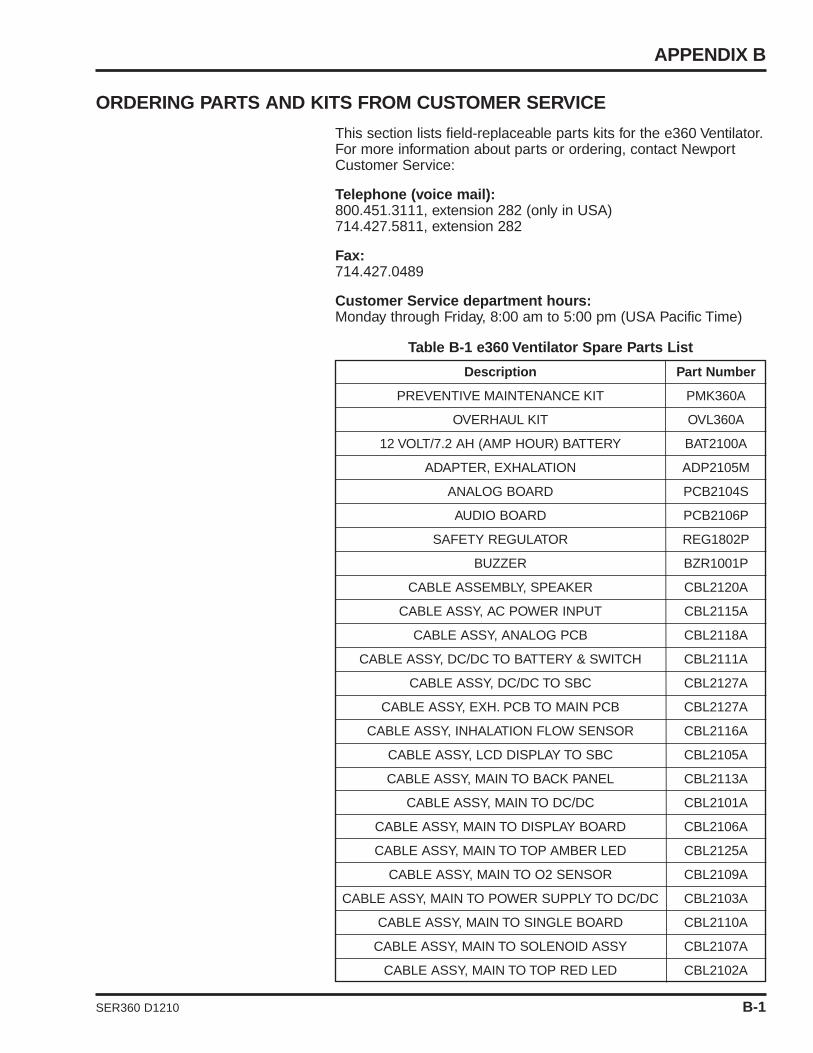
APPENDIX B
Description Part Number
PREVENTIVE MAINTENANCE KIT PMK360A
OVERHAUL KIT OVL360A
12 VOLT/7.2 AH (AMP HOUR) BATTERY BAT2100A
ADAPTER, EXHALATION ADP2105M
ANALOG BOARD PCB2104S
AUDIO BOARD PCB2106P
SAFETY REGULATOR REG1802P
BUZZER BZR1001P
CABLE ASSEMBLY, SPEAKER CBL2120A
CABLE ASSY, AC POWER INPUT CBL2115A
CABLE ASSY, ANALOG PCB CBL2118A
CABLE ASSY, DC/DC TO BATTERY & SWITCH CBL2111A
CABLE ASSY, DC/DC TO SBC CBL2127A
CABLE ASSY, EXH. PCB TO MAIN PCB CBL2127A
CABLE ASSY, INHALATION FLOW SENSOR CBL2116A
CABLE ASSY, LCD DISPLAY TO SBC CBL2105A
CABLE ASSY, MAIN TO BACK PANEL CBL2113A
CABLE ASSY, MAIN TO DC/DC CBL2101A
CABLE ASSY, MAIN TO DISPLAY BOARD CBL2106A
CABLE ASSY, MAIN TO TOP AMBER LED CBL2125A
CABLE ASSY, MAIN TO O2 SENSOR CBL2109A
CABLE ASSY, MAIN TO POWER SUPPLY TO DC/DC CBL2103A
CABLE ASSY, MAIN TO SINGLE BOARD CBL2110A
CABLE ASSY, MAIN TO SOLENOID ASSY CBL2107A
CABLE ASSY, MAIN TO TOP RED LED CBL2102A
SER360 D1210 B-1
ORDERING PARTS AND KITS FROM CUSTOMER SERVICE
This section lists field-replaceable parts kits for the e360 Ventilator.For more information about parts or ordering, contact NewportCustomer Service:
Telephone (voice mail):800.451.3111, extension 282 (only in USA)714.427.5811, extension 282
Fax:714.427.0489
Customer Service department hours:Monday through Friday, 8:00 am to 5:00 pm (USA Pacific Time)
Table B-1 e360 Ventilator Spare Parts List

ORDERING & CONTACT INFORMATION
Description Part Number
CABLE ASSY, SBC TO BACKPANEL VGA PORT CBL2104A
CABLE ASSY, SBC TO TOUCH PANEL CONTROLLER CBL2112A
CABLE ASSY, USB TO SBC CBL2114A
CABLE, GROUND CBL2144M
CABLE, OUTSIDE EXHALATION FLOW CBL2123P
CALE ASSY, DC/DC FAN CBL2119A
DIAPHRAGM, EXHALATION VALVE DIA1810M
CABLE, SBC RESET CBL2133A
CABLE, POWER SEQUENCE TO PCB2101A CBL2135A
CABLE, POWER SEQUENCE TO SBC CBL2136A
DISPLAY BOARD PCB2102A
DISPLAY, LCD DSP2105P
EMERGENCY RELIEF DIAPHRAGM DIA1800M
EXHALATION FLOW SENSOR FLS2101P
EXHILATION FLOW SENSOR BOARD PCB2103P
EXHILATION VALVE ASSEMBLY EXH2105A
FAN FILTER, EMI FLT2100P
FUSE – 2A SLO-BLO FUS1802Q
HEATER ASSEMBLY HTR2100A
INSIDE EXH. FLOW CABLE ADULT CBL2124P
LED, AMBER, TOP LED2102P
LED, RED, TOP LED2101P
MAIN BOARD PCB2100A
SPEAKER SPK2103M
OXYGEN SENSOR SEN2103P
MODULE, POWER ENTRY FUH1800P
OPTICAL ENCODER ENC1800P
POWER CORD PWR1500P
POWER SEQUENCE BOARD PCB2107A
POWER SUPPLY BOARD PCB2101A
POWER SWITCH BOX ASSEMBLY SWI1810A
EXHALATION SERVO REGULATOR REG1701P
REGULATOR, INLET REG1800P
SBC/GUI, e360 COMPACT FLASH CF2105A
B-2 SER360 D1210
Table B-1 e360 Ventilator Spare Parts List, cont.
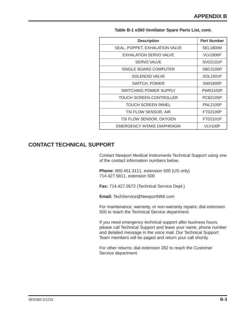
APPENDIX B
Table B-1 e360 Ventilator Spare Parts List, cont.
CONTACT TECHNICAL SUPPORT
Contact Newport Medical Instruments Technical Support using oneof the contact information numbers below.
Phone: 800.451.3111, extension 500 (US only)714.427.5811, extension 500
Fax: 714.427.0572 (Technical Service Dept.)
Email: [email protected]
For maintenance, warranty, or non-warranty repairs: dial extension500 to reach the Technical Service department.
If you need emergency technical support after business hours,please call Technical Support and leave your name, phone numberand detailed message in the voice mail. Our Technical SupportTeam members will be paged and return your call shortly.
For other returns: dial extension 282 to reach the CustomerService department.
Description Part Number
SEAL, POPPET, EXHALATION VALVE SEL1800M
EXHALATION SERVO VALVE VLV1806P
SERVO VALVE SVO2101P
SINGLE BOARD COMPUTER SBC2100P
SOLENOID VALVE SOL1501P
SWITCH, POWER SWI1800P
SWITCHING POWER SUPPLY PWR2100P
TOUCH SCREEN CONTROLLER PCB2105P
TOUCH SCREEN PANEL PNL2105P
TSI FLOW SENSOR, AIR FTD2100P
TSI FLOW SENSOR, OXYGEN FTD2101P
EMERGENCY INTAKE DIAPHRAGM VLV100P
SER360 D1210 B-3

ORDERING & CONTACT INFORMATION
B-4 SER360 D1210
RETURN e360 FOR REPAIR
Follow these steps to return your e360 Ventilator for repair:
1 Obtain a returned goods authorization (RGA) number from Newport Technical Support at the numbers given above.The RGA number helps to identify your repair and avoid service delays.
2 Unless requested to do otherwise, remove all accessories from the ventilator except the inlet water traps. Do not send accessories to Newport.
3 Package the ventilator in the original packing material, if available. If the original packing material is not available, call the Customer Service department to order a replacement box.Package parts or accessories (if requested) for safe shipping (original packing materials are not required).
SUBMIT A PRODUCT COMPLAINT
If your ventilator is not functioning properly (malfunctions) or a partof your ventilator is defective, a “Product Complaint Report” isrequired before any warranty replacement is authorized and/or aRGA number is issued. To submit a “Product Complaint Report”,go to the Newport website WWW.VENTILATORS.COM and clickon Customer Support / Complaint Report. Fill out the form com-pletely with as much detail as possible and submit. A TechnicalSupport Team member will review your product complaint and con-tact you shortly to resolve any issues you may have.
If you would like to request an RGA number for other returns oroffer a product improvement suggestion, you can also use theProduct Complaint Report.

APPENDIX C: DIAGRAMS
e360 System Electrical Block Diagram ................ C-1e360 System Pneumatic Diagram ........................ C-2
SER360 D1210

APPENDIX CDIAGRAMS
SYSTEM ELECTRICALBLOCK DIAGRAM
SER360 D1210 SER360 D1210 1

APPENDIX C
e360 SYSTEMPNEUMATIC DIAGRAM
SPD2100A
DIAGRAMS
SER360 D1210 SER360 D1210 C-2